WO2012020602A1 - ディスク型mems振動子 - Google Patents
ディスク型mems振動子 Download PDFInfo
- Publication number
- WO2012020602A1 WO2012020602A1 PCT/JP2011/063992 JP2011063992W WO2012020602A1 WO 2012020602 A1 WO2012020602 A1 WO 2012020602A1 JP 2011063992 W JP2011063992 W JP 2011063992W WO 2012020602 A1 WO2012020602 A1 WO 2012020602A1
- Authority
- WO
- WIPO (PCT)
- Prior art keywords
- disk
- vibrator
- type
- cross
- support structure
- Prior art date
- Legal status (The legal status is an assumption and is not a legal conclusion. Google has not performed a legal analysis and makes no representation as to the accuracy of the status listed.)
- Ceased
Links
Images


Classifications
-
- H—ELECTRICITY
- H02—GENERATION; CONVERSION OR DISTRIBUTION OF ELECTRIC POWER
- H02N—ELECTRIC MACHINES NOT OTHERWISE PROVIDED FOR
- H02N1/00—Electrostatic generators or motors using a solid moving electrostatic charge carrier
- H02N1/002—Electrostatic motors
- H02N1/006—Electrostatic motors of the gap-closing type
- H02N1/008—Laterally driven motors, e.g. of the comb-drive type
-
- H—ELECTRICITY
- H03—ELECTRONIC CIRCUITRY
- H03H—IMPEDANCE NETWORKS, e.g. RESONANT CIRCUITS; RESONATORS
- H03H3/00—Apparatus or processes specially adapted for the manufacture of impedance networks, resonating circuits, resonators
- H03H3/007—Apparatus or processes specially adapted for the manufacture of impedance networks, resonating circuits, resonators for the manufacture of electromechanical resonators or networks
- H03H3/0072—Apparatus or processes specially adapted for the manufacture of impedance networks, resonating circuits, resonators for the manufacture of electromechanical resonators or networks of microelectro-mechanical resonators or networks
-
- H—ELECTRICITY
- H03—ELECTRONIC CIRCUITRY
- H03H—IMPEDANCE NETWORKS, e.g. RESONANT CIRCUITS; RESONATORS
- H03H9/00—Networks comprising electromechanical or electro-acoustic elements; Electromechanical resonators
- H03H9/02—Details
- H03H9/02244—Details of microelectro-mechanical resonators
- H03H9/02338—Suspension means
-
- H—ELECTRICITY
- H03—ELECTRONIC CIRCUITRY
- H03H—IMPEDANCE NETWORKS, e.g. RESONANT CIRCUITS; RESONATORS
- H03H9/00—Networks comprising electromechanical or electro-acoustic elements; Electromechanical resonators
- H03H9/24—Constructional features of resonators of material which is not piezoelectric, electrostrictive, or magnetostrictive
- H03H9/2405—Constructional features of resonators of material which is not piezoelectric, electrostrictive, or magnetostrictive of microelectro-mechanical resonators
- H03H9/2436—Disk resonators
Definitions
- the present invention relates to a disk-type vibrator (resonator) manufactured by MEMS, and in particular, the present invention relates to a support structure for the vibrator.
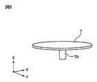
- the conventional disk-type MEMS vibrator has the same configuration as that of the disk-type MEMS vibrator according to the present invention, and includes a disk-shaped vibrating body (disk) 1 and the vibrating body 1.
- Drive electrodes 2 and 2 that are disposed opposite to each other with a predetermined gap g with respect to the outer peripheral portion 1a of the vibrating body 1, and an in-phase AC bias voltage is applied to the drive electrodes 2 and 2 respectively.
- the vibrating body 1 is supported at its center O by a columnar support structure 1b having a circular cross section.
- a disc type resonator resonator
- MEMS silicon substrate M icro E lectro M echanical S ystems Abbreviation, microelectromechanical systems
- JP 2007-152501 A M.M. A. Abdelmoneum, M .; U. Demirci, and C.I. T.A. -O. Nguyen, “Stemless wine-glass-mode disk micromechanical resonators,” Proceedings, 16th Int. IEEE Micro Electro Mechanical Systems Conf. Kyoto, Japan, Jan. 19-23, 2003, pp.
- the columnar body constituting the support structure that supports the vibrating body has a circular cross-sectional shape. Due to the variation in the dimensional accuracy of the columnar body cross section, the variation in the resonance frequency obtained from the vibrating body was large, and the energy loss leaked to the support structure was large. Therefore, there are problems that a predetermined resonance frequency cannot be obtained and the Q value is greatly reduced.
- the shape of the cross section of the support structure of the vibrating body is a noncircular cross section, for example, a square, a cross (cross) shape, a rectangle, an oval cross section.
- the disk-type MEMS vibrator of the present invention has a disk-type vibrating body and a predetermined gap with respect to the outer peripheral portion of the disk-type vibrating body on both sides of the disk-shaped vibrating body.
- a drive electrode a means for applying an in-phase AC bias voltage to the drive electrode, and a detection means for obtaining an output corresponding to a capacitance between the disk-type vibrating body and the drive electrode.
- the disk-type vibrating body is supported by a columnar support structure provided upright at the center of the disk, and the cross-sectional shape of the support structure is non-circular It is characterized by that.
- the non-circular cross-sectional shape of the support structure is a square, a cross, a rectangle, or an oval.
- each side of the cross-sectional shape of the support structure has an inner angle between the X axis and the Y axis of 45. It is configured to rotate around the Z-axis so as to be at 0 °.
- the vibrator is made of single crystal silicon or polycrystalline silicon.
- the disc-type vibrator is manufactured by MEMS.
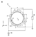
- FIG. 1 is a conceptual configuration diagram of a disk-type MEMS vibrator according to the present invention.
- FIG. 2 is a perspective view showing a vibrating body and a support structure of the disk-type MEMS vibrator of the present invention shown in FIG.
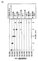
- FIG. 3 is a graph showing the relationship between the a dimension of the cross-sectional shape of the support structure of the disk-type MEMS vibrator of the present invention and the resonance frequency.
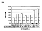
- FIG. 4 is a graph showing a relative value of the Q value of each cross-sectional shape of the support structure of the disk-type MEMS vibrator of the present invention with respect to a circular model.
- FIG. 5 is a process diagram showing a manufacturing process of the disk-type MEMS vibrator of the present invention.
- FIG. 6 is a perspective view showing a vibrating body and a support structure of a conventional disk-type MEMS vibrator.
- FIG. 1 is a conceptual configuration diagram of a disk-type MEMS vibrator according to the present invention.
- a disk-type MEMS vibrator R of the present invention includes a disk-shaped vibrating body (disk) 1 made of an elastic body, and the outer periphery of the vibrating body 1 on both sides of the vibrating body 1.
- a pair of drive electrodes 2 and 2 arranged to face each other with a predetermined gap g, an AC power supply 2a for applying an in-phase AC bias voltage to the pair of drive electrodes 2 and 2, and a vibrating body 1 and a pair of detection electrodes 3 and 3 for obtaining an output corresponding to the capacitance of the gap g between the drive electrodes 2 and 2 and the detection means 3a.
- the vibrating body 1 has a center O shown in FIG. It is supported by a columnar support structure 1a having a non-circular cross-sectional shape.
- a disk-type MEMS vibrator when an electric signal having a predetermined frequency is applied from the power source 2a shown in FIG. 1 to the drive electrodes 2 and 2, the vibrating body (disk) 1 has been described above by electrostatic coupling. It vibrates in a wine glass vibration mode (Wine-Glass-Vibrating-Mode) at a frequency.
- the detection electrodes 3 and 3 detect electrical vibration of the vibrating body 1 by electrostatic coupling, and output the detected signal to the detector 3a.
- the center O of the vibrating body 1 and the four nodes (nodes) n do not vibrate.
- the present invention relates to a cross-sectional shape of a support structure that supports a center O of a vibrating body 1 that does not vibrate during vibration.
- the disc-shaped vibrating body 1 made of an elastic body used in the present invention is made of single crystal silicon or polycrystalline silicon.
- the disk shown in FIG. The diameter d of No. 1 was 64 ⁇ m, the thickness t was 2 ⁇ m, the width w of the drive electrode 2 arranged oppositely was 40 ⁇ m, and the center O of the disk 1 was supported by the support structure 1a.
- the cross-sectional shape of the support structure 1a is a square, a cross (cross) shape, a rectangle, an ellipse rounded at four corners of the rectangle, and the drive electrodes 2 and 2 as shown in FIG. If it is arranged on the XY plane symmetrically with respect to the Y axis, the Z axis is set so that the inner angle between each side of the square, cross (cross), rectangle, or oval and the X axis is 45 °.
- a support structure was selected by selecting the cross-sectional shape rotated around.
- the support structure may have a cross-sectional shape obtained by rounding each corner of the above-described square, cross, or rectangular cross-section.
- Test Example To compare the cross-sectional shape of each support structure of the disk-type MEMS vibrator of the present invention and the conventional disk-type MEMS vibrator (circular model) with the relative values of the resonance frequency and the Q value, as shown in Table 2.
- five types of MEMS vibrators were manufactured by changing the dimension a substantially matching the conventional circular cross-sectional shape of the reference cross-sectional shape of the support structure 1a from 1 ⁇ m to 5 ⁇ m by 1 ⁇ m. Then, the resonance frequency (kHz) corresponding to the influence on the deviation from each a dimension is measured, and the Q value when the deviation (variation) in the a dimension of the cross-sectional shape of each support structure 4a is 3 ⁇ m.
- FIG. 3 shows the measured resonance frequency shown in Table 2 on the Y axis for each cross-sectional shape with the a dimension of each support structure on the X axis shown in Table 1 and the resonance frequency on the Y axis. The plot is shown in. From FIG. 3, the cross-sectional shape of the support structure 1 a is larger than the circular shape (conventional example) in the non-circular cross-sectional shape (square, cross (cross) shape, rectangle, oval shape).
- the amount of change in the resonance frequency with respect to the variation is small, and in particular, the amount of change in the square cross section is the smallest. Further, it was proved that the cross-sectional shape rotated by 45 ° around the Z-axis has a smaller amount of change in the resonance frequency with respect to the variation of the dimension a compared with the same cross-sectional shape. Further, in FIG. 4, the a dimension shown in Table 2 is 3 ⁇ m (1 ⁇ m to 5 ⁇ m) when the Q value of a MEMS vibrator (circular model) having a circular cross-sectional shape of the support structure (conventional example) is 100%.
- the relative value of the Q value of the vibrator having the support structure of each cross-sectional shape is shown.
- the cross-sectional shape of the support structure is not circular (conventional example), but the non-circular cross-sectional shape (square, cross (cross), rectangular, ellipse (ellipse)) is better. It was demonstrated that the Q value was large. From the test examples described above, the cross-sectional shape of the support structure is a non-circular shape, such as a square, a cross (cross) shape, a rectangular shape, and an oval shape, rather than a circular shape (conventional example).
- the change amount of the resonance frequency is smaller and the Q value is larger than that of the disk type MEMS vibrator in which the conventional support structure has a circular cross-sectional shape.
- a disk-type MEMS vibrator can be provided.
- a semiconductor substrate 6 made of Si is prepared, and a first insulating film 7 made of PSG (phosphor silicate glass) or the like is formed on the surface 6a.
- a second insulating film 8 made of silicon nitride or the like is formed on the surface of the first insulating film 7 by CVD, sputtering or the like.
- a conductive layer made of a polysilicon film (Doped poly Si) doped with phosphorus or boron to impart conductivity to the surface of the second insulating film 8 described above.
- a sacrificial layer 11 made of PSG or the like is formed on the surface of the conductive layer 10 by film formation such as CVD or sputtering, and the same as shown in FIG. 5B above.
- a part of the sacrificial layer 11 in which the support structure 1a is located on the vibrating body (disk) 1 of the MEMS vibrator shown in FIG. 1 is removed by etching.
- the surface (upper surface) of the sacrificial layer 11 may be planarized by chemical mechanical polishing (CMP) or the like.
- CMP chemical mechanical polishing
- the resist 9b is stripped.
- a conductive film formed of a doped polysilicon film or the like is formed on the sacrificial layer 11 by CVD, sputtering or the like, and the surface (upper surface) of the vibrator structure forming layer 1 is formed.
- the oxide film 12 made of NSG (undoped silicate glass) is formed by CVD, sputtering or the like.
- patterning treatment such as application of the resist 9c similar to the above-mentioned process is performed, and the support structure 1a A disk-shaped vibrator structure 1 (see FIG. 1) is formed.
- the surface (upper surface) of the conductive film 1 may be planarized by chemical mechanical polishing (CMP) or the like.
- CMP chemical mechanical polishing
- the resist 9c is peeled off.
- an oxide film 13 made of NSG (undoped silicate glass) is formed on the surface (upper surface) of the vibrator structure forming layer 1 previously formed by CVD, sputtering, or the like.
- the same patterning process as in the previous step such as application of the resist 9d is performed.
- the resist 9d is peeled off.
- another conductive layer 2, 3 made of a doped polysilicon film is formed on the trace of the resist 9d being peeled off by CVD, sputtering or the like in the step shown in FIG. 5 (e).
- the film is formed and subjected to the same patterning process as in the previous step, so that the drive electrode 2 and the detection electrode 3 are formed.
- the sacrificial layer 11 and the oxide films 12 and 13 are removed by etching using a hydrofluoric acid-based etchant, etc., so that the outer periphery of the vibrator structure 1 (disk) is removed. And the drive electrode 2 and the detection electrode 3 are separated from each other while maintaining a predetermined gap g, and the lower surface of the vibrator structure forming layer 1 (disk) is separated from the semiconductor substrate 6 (disk type) MEMS vibrator) is manufactured.
- the disk-type MEMS vibrator of the present invention can be widely used for resonators, SAW devices, sensors, actuators, and the like.
Landscapes
- Physics & Mathematics (AREA)
- Acoustics & Sound (AREA)
- Engineering & Computer Science (AREA)
- Manufacturing & Machinery (AREA)
- Piezo-Electric Or Mechanical Vibrators, Or Delay Or Filter Circuits (AREA)
- Micromachines (AREA)
Priority Applications (1)
| Application Number | Priority Date | Filing Date | Title |
|---|---|---|---|
| US13/814,736 US20130134829A1 (en) | 2010-08-11 | 2011-06-13 | Disk type mems resonator |
Applications Claiming Priority (2)
| Application Number | Priority Date | Filing Date | Title |
|---|---|---|---|
| JP2010180357A JP5667391B2 (ja) | 2010-08-11 | 2010-08-11 | ディスク型mems振動子 |
| JP2010-180357 | 2010-08-11 |
Publications (1)
| Publication Number | Publication Date |
|---|---|
| WO2012020602A1 true WO2012020602A1 (ja) | 2012-02-16 |
Family
ID=45567572
Family Applications (1)
| Application Number | Title | Priority Date | Filing Date |
|---|---|---|---|
| PCT/JP2011/063992 Ceased WO2012020602A1 (ja) | 2010-08-11 | 2011-06-13 | ディスク型mems振動子 |
Country Status (3)
| Country | Link |
|---|---|
| US (1) | US20130134829A1 (https=) |
| JP (1) | JP5667391B2 (https=) |
| WO (1) | WO2012020602A1 (https=) |
Families Citing this family (1)
| Publication number | Priority date | Publication date | Assignee | Title |
|---|---|---|---|---|
| CN103338022B (zh) * | 2013-07-22 | 2016-03-09 | 中国科学院半导体研究所 | 频率可调的mems谐振器 |
Citations (4)
| Publication number | Priority date | Publication date | Assignee | Title |
|---|---|---|---|---|
| JP2006518119A (ja) * | 2002-12-17 | 2006-08-03 | ザ リージェンツ オブ ザ ユニバーシティ オブ ミシガン | マイクロメカニカル共鳴装置およびマイクロメカニカル装置の製造方法 |
| JP2006217207A (ja) * | 2005-02-03 | 2006-08-17 | Seiko Epson Corp | 振動子及び半導体装置 |
| JP2007152501A (ja) * | 2005-12-06 | 2007-06-21 | Seiko Epson Corp | Mems振動子及びその製造方法 |
| JP2008504771A (ja) * | 2004-07-01 | 2008-02-14 | コミツサリア タ レネルジー アトミーク | 変形量が大きな複合型微小共振器 |
Family Cites Families (3)
| Publication number | Priority date | Publication date | Assignee | Title |
|---|---|---|---|---|
| ATE417021T1 (de) * | 2001-11-09 | 2008-12-15 | Wispry Inc | Mems-einrichtung mit dreischichtigem strahl und diesbezügliche verfahren |
| US6894586B2 (en) * | 2003-05-21 | 2005-05-17 | The Regents Of The University Of California | Radial bulk annular resonator using MEMS technology |
| WO2007110928A1 (ja) * | 2006-03-28 | 2007-10-04 | Fujitsu Limited | 可動素子 |
-
2010
- 2010-08-11 JP JP2010180357A patent/JP5667391B2/ja not_active Expired - Fee Related
-
2011
- 2011-06-13 WO PCT/JP2011/063992 patent/WO2012020602A1/ja not_active Ceased
- 2011-06-13 US US13/814,736 patent/US20130134829A1/en not_active Abandoned
Patent Citations (4)
| Publication number | Priority date | Publication date | Assignee | Title |
|---|---|---|---|---|
| JP2006518119A (ja) * | 2002-12-17 | 2006-08-03 | ザ リージェンツ オブ ザ ユニバーシティ オブ ミシガン | マイクロメカニカル共鳴装置およびマイクロメカニカル装置の製造方法 |
| JP2008504771A (ja) * | 2004-07-01 | 2008-02-14 | コミツサリア タ レネルジー アトミーク | 変形量が大きな複合型微小共振器 |
| JP2006217207A (ja) * | 2005-02-03 | 2006-08-17 | Seiko Epson Corp | 振動子及び半導体装置 |
| JP2007152501A (ja) * | 2005-12-06 | 2007-06-21 | Seiko Epson Corp | Mems振動子及びその製造方法 |
Also Published As
| Publication number | Publication date |
|---|---|
| JP2012039557A (ja) | 2012-02-23 |
| US20130134829A1 (en) | 2013-05-30 |
| JP5667391B2 (ja) | 2015-02-12 |
Similar Documents
| Publication | Publication Date | Title |
|---|---|---|
| CN102148613B (zh) | 一种固体介质层谐振器及其制备方法 | |
| JP6644355B2 (ja) | 共振子及び共振装置 | |
| EP3210303A1 (en) | Compound spring mems resonator for oscillators and real-time clock applications | |
| JP2009529820A (ja) | 少なくとも1個の共振器モード形状を有するmems共振器 | |
| US20130093527A1 (en) | Transverse acoustic wave resonator, oscillator having the resonator and method for making the resonator | |
| CN102868384B (zh) | 微机械谐振器 | |
| WO2012020601A1 (ja) | ディスク型mems振動子 | |
| EP3210302A1 (en) | Multiple coil spring mems resonator for oscillators and real-time clock applications | |
| US9413333B2 (en) | Nanomechanical resonator array and production method thereof | |
| JP5667391B2 (ja) | ディスク型mems振動子 | |
| CN104821799B (zh) | 一种压电式双方块级联微机械滤波器 | |
| JP4341288B2 (ja) | Mems型共振器及びその製造方法、並びにフィルタ | |
| JP2007005909A (ja) | 電気機械信号選択素子、その製造方法およびそれを用いた電気機器 | |
| JP5558869B2 (ja) | Mems | |
| JP2009088854A (ja) | マイクロメカニカル共振器およびその製造方法 | |
| JP2009094798A (ja) | マイクロメカニカル共振器 | |
| Liu et al. | Novel narrowband radio frequency microelectromechanical systems filters | |
| Hashimoto et al. | Evaluation of a single-crystal-silicon microelectromechanical systems resonator utilizing a narrow gap process | |
| US20100327993A1 (en) | Micro mechanical resonator | |
| Oka et al. | Characterization of four-points-pinned ring-shaped silicon microelectromechanical systems resonator | |
| Dong et al. | Anchor loss variation in MEMS Wine-Glass mode disk resonators due to fluctuating fabrication process | |
| Zaman | Hybrid RF Acoustic Resonators and Arrays with Integrated Capacitive and Piezoelectric Transducers | |
| Kiso et al. | High quality factor 80 MHz microelectromechanical systems resonator utilizing torsional-to-transverse vibration conversion | |
| JP2010145122A (ja) | 圧電振動子および振動ジャイロ装置 | |
| Bijari | Design and Fabrication of a Narrow-Bandwidth Micromechanical Ring Filter Using a Novel Process in Uvliga Technology |
Legal Events
| Date | Code | Title | Description |
|---|---|---|---|
| 121 | Ep: the epo has been informed by wipo that ep was designated in this application |
Ref document number: 11816268 Country of ref document: EP Kind code of ref document: A1 |
|
| WWE | Wipo information: entry into national phase |
Ref document number: 13814736 Country of ref document: US |
|
| NENP | Non-entry into the national phase |
Ref country code: DE |
|
| 122 | Ep: pct application non-entry in european phase |
Ref document number: 11816268 Country of ref document: EP Kind code of ref document: A1 |