WO2012017667A1 - ガス用調圧弁 - Google Patents
ガス用調圧弁 Download PDFInfo
- Publication number
- WO2012017667A1 WO2012017667A1 PCT/JP2011/004438 JP2011004438W WO2012017667A1 WO 2012017667 A1 WO2012017667 A1 WO 2012017667A1 JP 2011004438 W JP2011004438 W JP 2011004438W WO 2012017667 A1 WO2012017667 A1 WO 2012017667A1
- Authority
- WO
- WIPO (PCT)
- Prior art keywords
- pressure
- valve
- valve body
- passage
- pressure regulating
- Prior art date
Links
Images


Classifications
-
- F—MECHANICAL ENGINEERING; LIGHTING; HEATING; WEAPONS; BLASTING
- F16—ENGINEERING ELEMENTS AND UNITS; GENERAL MEASURES FOR PRODUCING AND MAINTAINING EFFECTIVE FUNCTIONING OF MACHINES OR INSTALLATIONS; THERMAL INSULATION IN GENERAL
- F16K—VALVES; TAPS; COCKS; ACTUATING-FLOATS; DEVICES FOR VENTING OR AERATING
- F16K31/00—Actuating devices; Operating means; Releasing devices
- F16K31/02—Actuating devices; Operating means; Releasing devices electric; magnetic
- F16K31/06—Actuating devices; Operating means; Releasing devices electric; magnetic using a magnet, e.g. diaphragm valves, cutting off by means of a liquid
-
- F—MECHANICAL ENGINEERING; LIGHTING; HEATING; WEAPONS; BLASTING
- F02—COMBUSTION ENGINES; HOT-GAS OR COMBUSTION-PRODUCT ENGINE PLANTS
- F02M—SUPPLYING COMBUSTION ENGINES IN GENERAL WITH COMBUSTIBLE MIXTURES OR CONSTITUENTS THEREOF
- F02M21/00—Apparatus for supplying engines with non-liquid fuels, e.g. gaseous fuels stored in liquid form
- F02M21/02—Apparatus for supplying engines with non-liquid fuels, e.g. gaseous fuels stored in liquid form for gaseous fuels
- F02M21/0218—Details on the gaseous fuel supply system, e.g. tanks, valves, pipes, pumps, rails, injectors or mixers
- F02M21/023—Valves; Pressure or flow regulators in the fuel supply or return system
- F02M21/0239—Pressure or flow regulators therefor
-
- F—MECHANICAL ENGINEERING; LIGHTING; HEATING; WEAPONS; BLASTING
- F02—COMBUSTION ENGINES; HOT-GAS OR COMBUSTION-PRODUCT ENGINE PLANTS
- F02M—SUPPLYING COMBUSTION ENGINES IN GENERAL WITH COMBUSTIBLE MIXTURES OR CONSTITUENTS THEREOF
- F02M21/00—Apparatus for supplying engines with non-liquid fuels, e.g. gaseous fuels stored in liquid form
- F02M21/02—Apparatus for supplying engines with non-liquid fuels, e.g. gaseous fuels stored in liquid form for gaseous fuels
- F02M21/0218—Details on the gaseous fuel supply system, e.g. tanks, valves, pipes, pumps, rails, injectors or mixers
- F02M21/0245—High pressure fuel supply systems; Rails; Pumps; Arrangement of valves
-
- F—MECHANICAL ENGINEERING; LIGHTING; HEATING; WEAPONS; BLASTING
- F16—ENGINEERING ELEMENTS AND UNITS; GENERAL MEASURES FOR PRODUCING AND MAINTAINING EFFECTIVE FUNCTIONING OF MACHINES OR INSTALLATIONS; THERMAL INSULATION IN GENERAL
- F16K—VALVES; TAPS; COCKS; ACTUATING-FLOATS; DEVICES FOR VENTING OR AERATING
- F16K31/00—Actuating devices; Operating means; Releasing devices
- F16K31/02—Actuating devices; Operating means; Releasing devices electric; magnetic
- F16K31/06—Actuating devices; Operating means; Releasing devices electric; magnetic using a magnet, e.g. diaphragm valves, cutting off by means of a liquid
- F16K31/0603—Multiple-way valves
- F16K31/061—Sliding valves
- F16K31/0613—Sliding valves with cylindrical slides
-
- F—MECHANICAL ENGINEERING; LIGHTING; HEATING; WEAPONS; BLASTING
- F16—ENGINEERING ELEMENTS AND UNITS; GENERAL MEASURES FOR PRODUCING AND MAINTAINING EFFECTIVE FUNCTIONING OF MACHINES OR INSTALLATIONS; THERMAL INSULATION IN GENERAL
- F16K—VALVES; TAPS; COCKS; ACTUATING-FLOATS; DEVICES FOR VENTING OR AERATING
- F16K31/00—Actuating devices; Operating means; Releasing devices
- F16K31/02—Actuating devices; Operating means; Releasing devices electric; magnetic
- F16K31/06—Actuating devices; Operating means; Releasing devices electric; magnetic using a magnet, e.g. diaphragm valves, cutting off by means of a liquid
- F16K31/0603—Multiple-way valves
- F16K31/0624—Lift valves
-
- F—MECHANICAL ENGINEERING; LIGHTING; HEATING; WEAPONS; BLASTING
- F16—ENGINEERING ELEMENTS AND UNITS; GENERAL MEASURES FOR PRODUCING AND MAINTAINING EFFECTIVE FUNCTIONING OF MACHINES OR INSTALLATIONS; THERMAL INSULATION IN GENERAL
- F16K—VALVES; TAPS; COCKS; ACTUATING-FLOATS; DEVICES FOR VENTING OR AERATING
- F16K31/00—Actuating devices; Operating means; Releasing devices
- F16K31/02—Actuating devices; Operating means; Releasing devices electric; magnetic
- F16K31/06—Actuating devices; Operating means; Releasing devices electric; magnetic using a magnet, e.g. diaphragm valves, cutting off by means of a liquid
- F16K31/0644—One-way valve
- F16K31/0655—Lift valves
-
- F—MECHANICAL ENGINEERING; LIGHTING; HEATING; WEAPONS; BLASTING
- F16—ENGINEERING ELEMENTS AND UNITS; GENERAL MEASURES FOR PRODUCING AND MAINTAINING EFFECTIVE FUNCTIONING OF MACHINES OR INSTALLATIONS; THERMAL INSULATION IN GENERAL
- F16K—VALVES; TAPS; COCKS; ACTUATING-FLOATS; DEVICES FOR VENTING OR AERATING
- F16K31/00—Actuating devices; Operating means; Releasing devices
- F16K31/12—Actuating devices; Operating means; Releasing devices actuated by fluid
- F16K31/42—Actuating devices; Operating means; Releasing devices actuated by fluid by means of electrically-actuated members in the supply or discharge conduits of the fluid motor
-
- G—PHYSICS
- G05—CONTROLLING; REGULATING
- G05D—SYSTEMS FOR CONTROLLING OR REGULATING NON-ELECTRIC VARIABLES
- G05D16/00—Control of fluid pressure
- G05D16/20—Control of fluid pressure characterised by the use of electric means
-
- G—PHYSICS
- G05—CONTROLLING; REGULATING
- G05D—SYSTEMS FOR CONTROLLING OR REGULATING NON-ELECTRIC VARIABLES
- G05D16/00—Control of fluid pressure
- G05D16/20—Control of fluid pressure characterised by the use of electric means
- G05D16/2006—Control of fluid pressure characterised by the use of electric means with direct action of electric energy on controlling means
- G05D16/2013—Control of fluid pressure characterised by the use of electric means with direct action of electric energy on controlling means using throttling means as controlling means
- G05D16/2022—Control of fluid pressure characterised by the use of electric means with direct action of electric energy on controlling means using throttling means as controlling means actuated by a proportional solenoid
-
- G—PHYSICS
- G05—CONTROLLING; REGULATING
- G05D—SYSTEMS FOR CONTROLLING OR REGULATING NON-ELECTRIC VARIABLES
- G05D7/00—Control of flow
- G05D7/03—Control of flow with auxiliary non-electric power
-
- H—ELECTRICITY
- H01—ELECTRIC ELEMENTS
- H01M—PROCESSES OR MEANS, e.g. BATTERIES, FOR THE DIRECT CONVERSION OF CHEMICAL ENERGY INTO ELECTRICAL ENERGY
- H01M8/00—Fuel cells; Manufacture thereof
- H01M8/04—Auxiliary arrangements, e.g. for control of pressure or for circulation of fluids
-
- H—ELECTRICITY
- H01—ELECTRIC ELEMENTS
- H01M—PROCESSES OR MEANS, e.g. BATTERIES, FOR THE DIRECT CONVERSION OF CHEMICAL ENERGY INTO ELECTRICAL ENERGY
- H01M8/00—Fuel cells; Manufacture thereof
- H01M8/04—Auxiliary arrangements, e.g. for control of pressure or for circulation of fluids
- H01M8/04082—Arrangements for control of reactant parameters, e.g. pressure or concentration
- H01M8/04201—Reactant storage and supply, e.g. means for feeding, pipes
- H01M8/04208—Cartridges, cryogenic media or cryogenic reservoirs
-
- H—ELECTRICITY
- H01—ELECTRIC ELEMENTS
- H01M—PROCESSES OR MEANS, e.g. BATTERIES, FOR THE DIRECT CONVERSION OF CHEMICAL ENERGY INTO ELECTRICAL ENERGY
- H01M2250/00—Fuel cells for particular applications; Specific features of fuel cell system
- H01M2250/20—Fuel cells in motive systems, e.g. vehicle, ship, plane
-
- Y—GENERAL TAGGING OF NEW TECHNOLOGICAL DEVELOPMENTS; GENERAL TAGGING OF CROSS-SECTIONAL TECHNOLOGIES SPANNING OVER SEVERAL SECTIONS OF THE IPC; TECHNICAL SUBJECTS COVERED BY FORMER USPC CROSS-REFERENCE ART COLLECTIONS [XRACs] AND DIGESTS
- Y02—TECHNOLOGIES OR APPLICATIONS FOR MITIGATION OR ADAPTATION AGAINST CLIMATE CHANGE
- Y02E—REDUCTION OF GREENHOUSE GAS [GHG] EMISSIONS, RELATED TO ENERGY GENERATION, TRANSMISSION OR DISTRIBUTION
- Y02E60/00—Enabling technologies; Technologies with a potential or indirect contribution to GHG emissions mitigation
- Y02E60/30—Hydrogen technology
- Y02E60/50—Fuel cells
-
- Y—GENERAL TAGGING OF NEW TECHNOLOGICAL DEVELOPMENTS; GENERAL TAGGING OF CROSS-SECTIONAL TECHNOLOGIES SPANNING OVER SEVERAL SECTIONS OF THE IPC; TECHNICAL SUBJECTS COVERED BY FORMER USPC CROSS-REFERENCE ART COLLECTIONS [XRACs] AND DIGESTS
- Y02—TECHNOLOGIES OR APPLICATIONS FOR MITIGATION OR ADAPTATION AGAINST CLIMATE CHANGE
- Y02T—CLIMATE CHANGE MITIGATION TECHNOLOGIES RELATED TO TRANSPORTATION
- Y02T10/00—Road transport of goods or passengers
- Y02T10/10—Internal combustion engine [ICE] based vehicles
- Y02T10/30—Use of alternative fuels, e.g. biofuels
-
- Y—GENERAL TAGGING OF NEW TECHNOLOGICAL DEVELOPMENTS; GENERAL TAGGING OF CROSS-SECTIONAL TECHNOLOGIES SPANNING OVER SEVERAL SECTIONS OF THE IPC; TECHNICAL SUBJECTS COVERED BY FORMER USPC CROSS-REFERENCE ART COLLECTIONS [XRACs] AND DIGESTS
- Y02—TECHNOLOGIES OR APPLICATIONS FOR MITIGATION OR ADAPTATION AGAINST CLIMATE CHANGE
- Y02T—CLIMATE CHANGE MITIGATION TECHNOLOGIES RELATED TO TRANSPORTATION
- Y02T90/00—Enabling technologies or technologies with a potential or indirect contribution to GHG emissions mitigation
- Y02T90/40—Application of hydrogen technology to transportation, e.g. using fuel cells
-
- Y—GENERAL TAGGING OF NEW TECHNOLOGICAL DEVELOPMENTS; GENERAL TAGGING OF CROSS-SECTIONAL TECHNOLOGIES SPANNING OVER SEVERAL SECTIONS OF THE IPC; TECHNICAL SUBJECTS COVERED BY FORMER USPC CROSS-REFERENCE ART COLLECTIONS [XRACs] AND DIGESTS
- Y10—TECHNICAL SUBJECTS COVERED BY FORMER USPC
- Y10T—TECHNICAL SUBJECTS COVERED BY FORMER US CLASSIFICATION
- Y10T137/00—Fluid handling
- Y10T137/7722—Line condition change responsive valves
- Y10T137/7758—Pilot or servo controlled
- Y10T137/7759—Responsive to change in rate of fluid flow
- Y10T137/776—Control by pressures across flow line valve
-
- Y—GENERAL TAGGING OF NEW TECHNOLOGICAL DEVELOPMENTS; GENERAL TAGGING OF CROSS-SECTIONAL TECHNOLOGIES SPANNING OVER SEVERAL SECTIONS OF THE IPC; TECHNICAL SUBJECTS COVERED BY FORMER USPC CROSS-REFERENCE ART COLLECTIONS [XRACs] AND DIGESTS
- Y10—TECHNICAL SUBJECTS COVERED BY FORMER USPC
- Y10T—TECHNICAL SUBJECTS COVERED BY FORMER US CLASSIFICATION
- Y10T137/00—Fluid handling
- Y10T137/7722—Line condition change responsive valves
- Y10T137/7758—Pilot or servo controlled
- Y10T137/7761—Electrically actuated valve
-
- Y—GENERAL TAGGING OF NEW TECHNOLOGICAL DEVELOPMENTS; GENERAL TAGGING OF CROSS-SECTIONAL TECHNOLOGIES SPANNING OVER SEVERAL SECTIONS OF THE IPC; TECHNICAL SUBJECTS COVERED BY FORMER USPC CROSS-REFERENCE ART COLLECTIONS [XRACs] AND DIGESTS
- Y10—TECHNICAL SUBJECTS COVERED BY FORMER USPC
- Y10T—TECHNICAL SUBJECTS COVERED BY FORMER US CLASSIFICATION
- Y10T137/00—Fluid handling
- Y10T137/7722—Line condition change responsive valves
- Y10T137/7781—With separate connected fluid reactor surface
- Y10T137/7793—With opening bias [e.g., pressure regulator]
- Y10T137/7797—Bias variable during operation
-
- Y—GENERAL TAGGING OF NEW TECHNOLOGICAL DEVELOPMENTS; GENERAL TAGGING OF CROSS-SECTIONAL TECHNOLOGIES SPANNING OVER SEVERAL SECTIONS OF THE IPC; TECHNICAL SUBJECTS COVERED BY FORMER USPC CROSS-REFERENCE ART COLLECTIONS [XRACs] AND DIGESTS
- Y10—TECHNICAL SUBJECTS COVERED BY FORMER USPC
- Y10T—TECHNICAL SUBJECTS COVERED BY FORMER US CLASSIFICATION
- Y10T137/00—Fluid handling
- Y10T137/7722—Line condition change responsive valves
- Y10T137/7781—With separate connected fluid reactor surface
- Y10T137/7793—With opening bias [e.g., pressure regulator]
- Y10T137/7801—Balanced valve
Definitions
- the present invention relates to a gas pressure regulating valve that regulates the pressure of high-pressure fuel gas to a pressure corresponding to an applied voltage or an applied current.
- Clean energy vehicles using fuel gas such as hydrogen gas and natural gas are known, such as fuel cell vehicles, hydrogen engine vehicles, and natural gas vehicles. These clean energy vehicles are equipped with a high-pressure tank and an injector or an electromagnetic pressure regulating valve, and move by supplying fuel gas stored in the high-pressure tank to a fuel cell or a gas engine by the injector or electromagnetic pressure regulating valve. ing.
- the injector and the electromagnetic pressure regulating valve can adjust the flow rate (or pressure) of the fuel gas supplied to the fuel cell or gas engine.
- the flow rate (or pressure) of the fuel gas can be adjusted by the injector or the electromagnetic pressure regulating valve. By adjusting the output, the output of the fuel cell or the gas engine is controlled.
- the injector can adjust the flow rate of the fuel gas by closing or opening its injection hole, and the flow rate of the fuel gas is changed according to the ratio of time for opening and closing the injection hole, that is, the duty ratio.
- the differential pressure between the upstream pressure and the output pressure of the injector is large, the flow rate of the fuel gas flowing when the injector injection hole is opened becomes extremely large, and the change in the flow rate of the fuel gas with respect to the change in the duty ratio of the injector becomes large.
- the flow rate gain (the value obtained by dividing the fuel gas flow rate by the duty ratio) becomes large and control becomes difficult.
- the upstream pressure of the injector becomes high, there is a problem that the duty control span from a small flow rate to a large flow rate becomes extremely narrow.
- the electromagnetic pressure regulating valve can adjust the flow rate of the fuel gas by adjusting the opening (opening area) of the valve passage. Therefore, when the upstream pressure of the electromagnetic pressure regulating valve increases, the differential pressure before and after the electromagnetic pressure regulating valve increases, and the flow rate of the flowing fuel gas changes greatly only by widening the opening slightly. The change in the flow rate of the fuel gas with respect to the change in the opening degree increases. Therefore, similarly to the injector, the pressure control of the fuel gas in the small flow rate region (low load state) is extremely difficult for the electromagnetic pressure regulating valve.
- two regulators are provided on the upstream side of the injector.
- the two regulators are arranged in series and depressurize the hydrogen gas supplied from the high-pressure tank in two stages.
- two regulators maintain the upstream pressure of the injector below a certain low pressure to reduce the differential pressure before and after the injector, thereby ensuring pressure controllability.
- a shutoff valve is provided upstream of the two regulators, and the shutoff valve shuts off the hydrogen tank and the fuel cell so that the supply of hydrogen gas can be stopped.
- the use limit pressure of the high-pressure tank must be set higher than the minimum operating pressure of the fuel cell or gas engine.
- the amount of fuel gas that can be used in the high-pressure tank is reduced as compared with the case where no regulator is provided, and the traveling range of the automobile is reduced.
- a diaphragm system may be used as a sealing system for electromagnetic pressure regulating valves, etc., but diaphragm seals generally have a low pressure resistance, so when handling high-pressure fuel gas, the fuel gas may enter the atmosphere due to diaphragm damage. There is a risk of leakage. On the other hand, in the case of the O-ring method, fuel gas may leak into the atmosphere due to an unexpected external factor at high pressure.
- the present invention provides a gas pressure regulating valve capable of adjusting the secondary pressure to a target pressure more accurately and preventing leakage of fuel gas into the atmosphere even in a high-pressure fuel gas environment.
- the purpose is that.
- the gas pressure regulating valve includes a housing having a valve passage connected to a primary port and a secondary port, and a position provided in the housing between a closed position for closing the valve passage and an open position for opening the valve passage.
- the valve body that moves by adjusting the opening of the valve passage, the return spring that urges the valve body in the direction of the closed position, and the driving force corresponding to the applied voltage or applied current applied for the return High pressure fuel supplied to the valve passage via the primary port, and provided with valve body drive means for moving the valve body in the open position direction to the valve body against the bias of the spring
- a pressure feedback chamber formed in the housing and connected to the secondary port; , The pressure in the pressure feedback chamber is the driving force.
- a first seal member that moves the valve body to the closed position according to the pressure in the pressure feedback chamber, and is interposed in a gap between the valve body and the housing.
- a bearing member that slides and supports, a second seal member that is provided on the valve passage side from the bearing member, and that is provided further on the valve passage side than the second seal member, and the gap
- a buffer chamber connected to the secondary port is formed between the third seal member and the second seal member.
- the secondary pressure can be regulated by changing the opening of the valve passage by changing the driving force of the valve body driving means.
- the secondary pressure is guided to the pressure feedback chamber, and the first seal member receives the secondary pressure of the pressure feedback chamber and moves the valve body to the closed position.
- the first seal member moves the valve body toward the open position.
- the secondary pressure is returned to a constant pressure corresponding to the driving force of the valve body driving means, and is held at the constant pressure regardless of the fluctuation of the primary pressure. Therefore, the gas pressure regulating valve has high pressure controllability, and can modulate the high-pressure fuel gas to the target pressure more accurately.
- the second seal member since the second seal member is disposed closer to the bearing member than the third seal member, even if fuel gas leaks from the third seal member, the second seal member causes the fuel gas to flow toward the bearing member. There is no leakage. Further, a buffer chamber is formed between the third seal member and the second seal member, and this buffer chamber is connected to the secondary port. Therefore, even if fuel gas leaks from the third seal member, it can enter the buffer chamber and be guided to the secondary side.
- the gas pressure regulating valve has a safety structure that guides the fuel gas leaked from the third seal member to the secondary side, and the fuel gas is external even if the space in which the bearing member is accommodated is connected to the outside. Can be prevented from being released.
- the valve body can be smoothly moved, and the followability to the target pressure can be improved.
- the second seal member is provided on the valve passage side of the bearing member, so that the fuel gas does not flow toward the bearing member and the bearing member is not exposed to the fuel gas.
- a material that does not have corrosion resistance to the fuel gas can be used for the bearing member, and the number of materials that can be selected increases.
- the bearing member is lubricated with grease
- the used grease can be prevented from flowing out to the secondary port side together with the fuel gas.
- the secondary port and the pressure feedback chamber are connected by a pressure feedback passage, and the pressure feedback passage is formed in the valve body.
- the rigidity of the housing can be improved, and fuel gas can be prevented from leaking into the atmosphere.
- the secondary port and the pressure feedback chamber are connected by a pressure feedback passage, and the pressure feedback passage is formed in the housing.
- the pressure return passage is also connected to the buffer chamber.
- the fuel gas leaking into the buffer chamber can be guided to the secondary side by the pressure feedback passage.
- the valve body and the housing can be miniaturized. That is, the gas pressure regulating valve can be downsized.
- the housing is a valve seat portion that is seated when the valve body is located at the closed position, and includes a valve seat portion that includes a valve seat surface orthogonal to the open position direction,
- the valve body is preferably seated on the valve seat surface at a valve body surface orthogonal to the open position direction.
- valve seat surface of the valve seat portion and the valve body surface of the valve body are both orthogonal to the open position direction. Plastically deforms in the position direction. Therefore, the sheet diameter hardly changes even when used repeatedly, and the pressure regulation characteristics do not change. Therefore, reliability and stability of the pressure regulation characteristics can be improved.
- valve passage includes a secondary side passage connected to a secondary port downstream from an orifice formed between the valve seat portion and the valve body
- valve body driving means includes Provided at a position outside the secondary passage and on the opposite side of the valve seat with the valve body interposed therebetween, and the valve body is pulled up and moved in the open position direction by the driving force. Is preferred.
- the electromagnetic pressure regulating valve for gas is configured with a pull-type structure in which the valve body can be pulled from the opposite side of the valve body surface by the valve body driving means and moved in the open position direction. Therefore, the valve body driving means can be arranged outside the secondary side passage on the valve body surface side of the valve body. As a result, the valve body driving means is arranged in the secondary side passage and the push area is pushed while ensuring the same flow area of the secondary side passage as the electromagnetic pressure regulating valve of the push type structure that pushes the valve body in the open position direction.
- the orifice diameter (that is, the seat diameter) can be made smaller than that of the electromagnetic pressure regulating valve having a mold structure.
- the change of the valve passage opening degree with respect to the stroke of the valve body can be reduced by reducing the seat diameter. Therefore, the valve passage opening can be finely adjusted compared to the push-type gas pressure regulating valve, and the stability of the pressure regulation accuracy of the gas pressure regulating valve can be improved.
- the valve seat portion is formed along an outer edge of a valve port that is an opening on the primary port side in the secondary passage, and protrudes in the open position direction toward the valve body,
- the valve body has a seat member at a position facing the valve seat portion, and one surface of the seat member forms the valve body surface, and the valve body surface is seated on a top portion of the valve seat portion. It is preferable that it is such.
- the valve body is a moving member, the seating position varies.
- the valve seat portion protrudes, the valve body surface of the valve body can be widened even if there is some variation.
- the body can be securely seated on the valve seat.
- the valve seat portion is formed along the outer edge of the valve port, the inner diameter size of the valve port and the inner diameter size of the valve seat portion can be substantially matched. As a result, the seat diameter can be reduced while ensuring the necessary flow path area, and the stability of the pressure regulation accuracy of the gas electromagnetic pressure regulation valve can be improved.
- the valve body receives the primary pressure of the primary port toward the open position and the pressure receiving area of the first pressure receiving surface and the pressure of the second pressure receiving surface that receives the primary pressure in the closing direction. It is preferable that the area is the same.
- the acting force that the valve body receives from the primary pressure can be offset.
- variation of a primary pressure can be eliminated, and the pressure controllability of a secondary pressure can further be improved.
- the driving force of the valve body driving means can be reduced. Therefore, the gas pressure regulating valve can be reduced in size.
- the valve body has a pressure receiving area of a first pressure receiving surface that receives the primary pressure of the primary port toward the open position, and a pressure receiving surface of the second pressure receiving surface that receives the primary pressure in the closing direction. It is preferable that it is formed to be smaller than the area.
- the valve body receives an acting force from the primary pressure toward the closed position.
- the valve body receives an acting force from the primary pressure in the direction of the closed position, the valve body is held in the closed position when the valve body driving means does not operate. Therefore, the valve passage can be closed firmly, and the fuel gas can be prevented from leaking from the primary side to the secondary side when the valve body driving means is not operating.
- the pressure feedback chamber is located on the side opposite to the second seal member with respect to the bearing member, and the first seal member is located between the bearing member and the pressure feedback chamber. And it is preferable to block between them.
- the first seal member can prevent the fuel gas guided to the pressure return chamber from flowing into the bearing member. Therefore, selection of the material used for a bearing member increases, and even if it lubricates a bearing member, grease does not mix in fuel gas.
- the pressure feedback chamber is located between the valve passage and the valve body driving means, and the first seal member is formed of the valve body driving means and the pressure feedback chamber. It is preferable to be located between the two and block between them.
- the fuel gas can be prevented from flowing to the valve body driving means side. Thereby, it can prevent that a valve body drive means is exposed to fuel gas, and when fuel gas is a corrosive fluid, it can prevent that the structural member of a valve body drive means corrodes. Further, even if the valve body driving means is disposed in the atmosphere, the fuel gas can be prevented from flowing out to the atmosphere via the valve body driving means.
- the first seal member is a diaphragm seal
- the second seal member is preferably a low pressure seal having a low frictional resistance
- the sliding friction by the first seal member can be eliminated by adopting the diaphragm seal as the first seal member. Moreover, sliding friction can be suppressed by adopting a low-pressure seal having a small frictional resistance as the second seal member. As a result, the valve body can be moved smoothly, and the secondary pressure can be quickly adjusted to a constant pressure corresponding to the driving force when the primary pressure fluctuates or when the driving force is changed. Therefore, the responsiveness of the secondary pressure can be improved.
- the third seal member is preferably a high pressure seal having a small frictional resistance and a small difference between the starting resistance and the sliding resistance.
- the valve body can be moved smoothly and the responsiveness of the valve body can be improved. Moreover, since it is a high pressure seal, the pressure resistance performance with respect to the primary pressure is improved, and the limit pressure of the primary pressure supplied from the primary port can be improved.
- valve body when the applied voltage or applied current applied to the valve body driving means is zero, it is preferable that the valve body is of a normally closed type in which the valve body is moved to the closed position by the return spring.
- the valve passage can be cut off urgently by cutting off the applied voltage or applied current applied to the valve body driving means.
- a gas pressure regulating valve capable of adjusting the secondary pressure to a target pressure more accurately and preventing leakage of fuel gas into the atmosphere even in a high-pressure fuel gas environment. can do.
- the pressure regulating valves 1 and 1A to 1V according to the first to twenty-second embodiments of the present invention and the fuel gas supply system 2 including the same will be described with reference to the drawings described above.
- the concept of the direction such as up and down, left and right, and front and back in the embodiment is used for convenience of description, and the arrangement and direction of the configurations of the pressure regulating valves 1 and 1A to 1V and the fuel gas supply system 2 are described. It is not suggested to limit the direction to that direction.
- the pressure regulating valves 1 and 1A to 1V and the fuel gas supply system 2 described below are only one embodiment of the present invention, and the present invention is not limited to the embodiment and is within a range not departing from the gist of the invention. Can be added, deleted and changed.
- the fuel gas supply system 2 is provided in a high-pressure tank 3 in which fuel gas such as hydrogen gas or compressed natural gas is stored at high pressure.
- the fuel gas supply system 2 is connected to a fuel gas consumer such as a fuel cell or a gas engine, and adjusts the high-pressure fuel gas to a desired low pressure and supplies it to the fuel gas consumer.
- the fuel gas supply system 2 configured as described above includes a container base valve 4, a pressure sensor 5, and an arithmetic controller 6.
- the container original valve 4 is configured as an on-tank type and is provided at the opening of the high-pressure tank 3.
- the container original valve 4 is not limited to the on-tank type, but may be an in-tank type.
- the container original valve 4 has an electromagnetic pressure regulating valve 1 and an electromagnetic shut-off valve 7.
- the electromagnetic shut-off valve 7 is provided in the supply path 2a that leads from the high-pressure tank 3 to the fuel gas consumer.
- the electromagnetic shut-off valve 7 is a so-called electromagnetic on-off valve and has a function of opening and closing the supply path 2a according to a signal transmitted thereto.
- the supply passage 2 a is provided with an electromagnetic pressure regulating valve 1 on the downstream side of the electromagnetic cutoff valve 7.
- the electromagnetic pressure regulating valve 1 has a function of regulating high-pressure fuel gas.
- a pressure sensor 5 is provided in the supply path 2 a downstream from the electromagnetic pressure regulating valve 1. The pressure sensor 5 detects the pressure of the fuel gas flowing through the supply path 2a.
- the pressure sensor 5 is connected to the calculation controller 6 via the signal line 8, and a detected pressure signal corresponding to the detected pressure is input to the calculation controller 6.
- a target pressure command signal corresponding to the target pressure is input to the arithmetic controller 6 from an input means, a control device or the like (not shown).
- the arithmetic controller 6 calculates a difference between the target pressure command signal and the detected pressure signal, and flows a current having a magnitude corresponding to the difference to the electromagnetic pressure regulating valve 1.
- the electromagnetic pressure regulating valve 1 regulates high-pressure fuel gas to a constant pressure corresponding to the flowed current.
- the electromagnetic pressure regulating valve 1 of the first embodiment is merely an example of an electromagnetic pressure regulating valve provided in the fuel gas supply system 2, and there are various other embodiments. In the following, several representative embodiments will be described in detail following the electromagnetic pressure regulating valve 1 of the first embodiment.
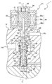
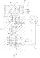
- the electromagnetic pressure regulating valve 1 according to the first embodiment shown in FIG.
- the housing 12 is attached to the opening of the high-pressure tank 3 (see FIG. 1) in a state where a seal is achieved.
- a primary port 12a, a valve body hole 12b, and a secondary port 12c are formed in the housing 12.
- the primary port 12a is connected to the electromagnetic shut-off valve 7 (see FIG. 1), and is connected to the valve body hole 12b via a primary side passage 12d formed in the housing 12.
- the valve element hole 12b extends along the axis L1 extending vertically, the lower side is closed, and the upper side is opened.
- the valve body hole 12b has a circular cross section, and has a valve space 12e formed in a middle portion thereof having a diameter larger than that of the remaining portion.
- the primary side passage 12d is connected to the valve space 12e.
- the valve body hole 12 b is connected to the secondary port 12 c through a secondary side passage 12 f formed in the housing 12.
- the secondary side passage 12f is connected to the valve element hole 12b in the secondary side region 12g above the valve space 12e.
- the secondary port 12c is connected with the fuel gas consumer via the supply path 2a (refer FIG. 1).
- the primary port 12a and the secondary port 12c are connected via the primary side channel
- the primary passage 12d, the valve space 12e, the secondary region 12g, and the secondary passage 12f constitute a valve passage 13 that connects the primary port 12a and the secondary port 12c.
- the housing 12 thus configured has a seat portion 15.
- the seat 15 is located in the vicinity of an opening that connects the secondary region 12g and the valve space 12e, and is formed so as to surround the opening.
- the valve body 14 is inserted in the housing 12 along the axis L1 of the valve body hole 12b, and the valve body 14 has inserted the front-end
- the valve body 14 is substantially cylindrical, and has a tapered portion 14b on the distal end portion 14a side.
- the tapered portion 14b is tapered toward the upper side, and when the valve body 14 is located at the closed position as shown in FIG. 2, the seat 14 is seated and the valve passage 13 is blocked. Yes.
- the lower end 14d side of the tapered portion 14b of the valve body 14 has an outer diameter substantially the same as the inner diameter of the secondary side region 12g.
- the housing 12 has a seal mounting portion 16 below the valve space 12e.
- the seal attachment portion 16 is formed on the inner surface of the housing 12 over the entire circumference in the circumferential direction.
- the inner diameter of the seal mounting portion 16 substantially matches the hole diameter of the secondary side region 12g and the outer diameter of the valve body 14. Further, the inner diameter of the housing 12 below the seal mounting portion 16 is larger than the inner diameter of the seal mounting portion 16.
- a generally annular bearing member accommodating space 17 is formed between the housing 12 and the valve body 14, and the bearing member 18 is accommodated in the bearing member accommodating space 17.
- the bearing member 18 is generally formed in a cylindrical shape, and is configured by, for example, a ball guide, a ball bearing, or a slide bearing.
- the bearing member 18 is externally mounted on the valve body 14 and interposed between the valve body 14 and the housing 12 to support the valve body 14. With this bearing member 18, the valve body 14 can move smoothly in the vertical direction along the axis L ⁇ b> 1 within the housing 12.
- the bearing member 18 is grease-lubricated to further smooth the movement of the valve body 14 and improve durability.
- a diaphragm seal 19 is provided below the bearing member accommodating space 17 in which the bearing member 18 is arranged in this way so as to close the space.
- the diaphragm seal 19 that is the first seal member is a so-called diaphragm, and has a generally annular shape.
- An outer edge portion of the diaphragm seal 19 is attached to the housing 12, and an inner edge portion is attached to the valve body 14. More specifically, the housing 12 is configured to be split into two vertically, and is attached to the housing 12 by sandwiching the outer edge portion of the diaphragm seal 19 between the two portions.
- the inner edge portion of the diaphragm seal 19 is attached to the valve body 14 by being sandwiched between the lower end portion of the valve body 14 and the attachment member 14c attached thereto.
- a high pressure seal member 20 is provided on the seal attachment portion 16 of the housing 12 so as to close the upper side of the bearing member accommodation space 17.
- the high-pressure seal member 20 that is the third seal member is a high-pressure seal that has a small frictional resistance and a small difference between the starting resistance and the sliding resistance, and is, for example, an O-ring that is surface-treated with a fluororesin or the like.
- the high-pressure seal member 20 is attached so as to fit into the inner peripheral portion of the seal attachment portion 16, and seals the gap between the valve body 14 and the seal attachment portion 16.
- a low pressure seal member 21 is provided in the seal attachment portion 16.
- the low-pressure seal member 21 as the second seal member is a substantially annular O-ring, and is surface-treated with a resin or the like to reduce the frictional resistance.
- the low-pressure seal member 21 is located closer to the bearing member 18 than the high-pressure seal member 20, and is attached so as to be fitted into the inner peripheral portion of the seal attachment portion 16.
- the low pressure seal member 21 seals the gap between the seal mounting portion 16 and the valve body 14, and forms a buffer chamber 22 between the high pressure seal member 20 and the low pressure seal member 21.
- the buffer chamber 22 reduces the pressure difference between the upper side and the lower side of the high-pressure seal member 20 to suppress leakage from the periphery of the high-pressure seal member 20 and leaks from the periphery of the high-pressure seal member 20 when the valve body 14 is moved. Fuel gas is captured. Further, since the trapped fuel gas is sealed between the buffer chamber 22 and the bearing housing space 17 by the low pressure seal member 21, the fuel gas is prevented from leaking toward the bearing housing space 17. .
- the high-pressure seal member 20 and the low-pressure seal member 21 may be attached so as to be fitted into the outer peripheral portion of the valve body 14.
- the bearing member housing space 17 whose upper and lower sides are closed by the diaphragm seal 19 and the low pressure seal member 21 in this way is another space formed in the housing 12 (for example, the valve space 12e and the secondary region 12g). Etc.).
- the bearing member accommodation spaces 17 that are separated in this way are opened to the atmosphere by an atmosphere communication passage 23 formed in the housing 12. Therefore, the grease that lubricates the bearing member 18 is not exposed to the fuel gas, and does not leak to other spaces in the housing 12, such as the valve space 12e and the secondary port 12c. Therefore, grease depletion can be suppressed and the lubrication state of the bearing member 18 can be maintained well. Thereby, while being able to improve the durability of the bearing member 18, the valve body 14 can be moved smoothly. It is also possible to prevent grease from being mixed into the fuel gas.
- a pressure feedback chamber 24 is formed below the diaphragm seal 19 in the valve body hole 12b.
- the pressure return chamber 24 is a substantially disk-shaped space surrounded by the bottom of the housing 12, the diaphragm seal 19, and the lower end of the valve body 14.
- a diaphragm seal 19 is located between the pressure return chamber 24 and the bearing member accommodation space 17, and the diaphragm seal 19 is closed between them.
- the pressure feedback chamber 24 is connected to the secondary region 12g of the valve passage 13 by a pressure equalizing passage 25.
- the pressure equalizing passage 25 is formed in the valve body 14, and includes a return chamber side communication portion 25a, a secondary side communication portion 25b, and a return portion 25c.
- the return chamber side communication portion 25a is open to the pressure return chamber 24, and extends from there to the tip end portion 14a along the axis of the valve body 14 (in the present embodiment, substantially coincides with the axis L1).
- the return chamber side communication part 25a is connected with the secondary side communication path 25b formed in the front-end
- the secondary side communication portion 25b extends so as to penetrate the valve body 14 in the radial direction, and both ends thereof are opened to the secondary side region 12g.
- the return portion 25 c penetrates the valve body 14 in the radial direction, is connected to the return chamber side communication portion 25 a on the inner side, and both ends thereof open to the buffer chamber 22.
- the buffer chamber 22 is connected to the pressure feedback chamber 24 and the secondary region 12g via the pressure equalizing passage 25.
- the pressure equalizing passage 25 connects the secondary port 12 c and the pressure feedback chamber 24, and supplies the secondary pressure p 2 to the pressure feedback chamber 24.
- the pressure equalizing passage 25 connects the secondary port 12c and the buffer chamber 22, and guides the fuel gas leaked into the buffer chamber 22 to the pressure feedback chamber 24 and the secondary port 12c. That is, the fuel gas trapped in the buffer chamber 22 returns to the secondary side region 12g through the pressure equalizing passage 25.
- the electromagnetic pressure regulating valve 1 is a valve having a safety structure that can return the fuel gas leaked from the primary region such as the valve space 12e to the secondary region without leaking outside.
- the secondary pressure p 2 Since the secondary pressure p 2 has a small differential pressure from the atmospheric pressure, there is almost no leakage from the periphery of the low pressure seal member 21 to the bearing housing space 17. Therefore, the secondary pressure p 2 in the buffer chamber 22 can be prevented from leaking to the atmosphere.
- valve body 14 has a flange 14e.
- the flange 14e is formed over the entire circumferential direction below the tapered portion 14b, and protrudes further outward in the radial direction from the tapered portion 14b.
- the flange 14 e is positioned so as to face the upper end of the seal attachment portion 16.
- a return spring 26 is disposed between the flange 14 e and the upper end of the seal mounting portion 16.
- the return spring 26 is a so-called compression coil spring, and is externally attached to the valve body 14 in a compressed state, and biases the valve body 14 in the closed position direction (the direction in which the valve body 14 is directed toward the closed position).
- the urged valve body 14 is seated on the seat portion 15 and closes the valve passage 13.
- An electromagnetic proportional solenoid 27 is provided at the opening end portion (that is, the upper end portion) of the housing 12 in order to apply a force against the urging force of the return spring 26 to the valve body 14.
- the electromagnetic proportional solenoid 27 which is the valve body driving means is screwed and fixed to the outer periphery of the opening end portion of the housing 12.
- the electromagnetic proportional solenoid 27 has a solenoid coil 28.
- the solenoid coil 28 is generally formed in a cylindrical shape, and the housing 12 is inserted into the lower end side thereof.
- the solenoid coil 28 has a substantially cylindrical case 28a, in which a bobbin 28b and a coil wire 28c are provided.
- the bobbin 28b is also formed in a substantially cylindrical shape, and the solenoid coil 28 is configured by winding the bobbin 28b around the coil wire 28c.
- a yoke 29 is provided at the lower end and the upper end is closed by a cover 30.
- a movable member 31 is provided between the yoke 29 and the cover 30.
- the movable member 31 is made of a magnetic material and has a substantially cylindrical shape.
- the movable member 31 is disposed along the axis L1.
- the outer diameter of the movable member 31 is smaller than the inner diameter of the solenoid coil 28, and an annular guide member 32 is interposed between the movable member 31 and the solenoid coil 28.
- the guide member 32 is made of a nonmagnetic material, and supports the movable member 31 so as to be slidable in the vertical direction along the axis L1.
- the yoke 29 is vertically opposed to the lower end portion of the movable member 31 with a space therebetween.
- the yoke 29 is made of a magnetic material, for example, electromagnetic stainless steel, and is formed in an approximately annular shape. The yoke 29 is magnetized by passing a current through the solenoid coil 28 and attracts the movable member 31.
- a compression coil spring 34 is provided between the upper end portion of the movable member 31 and the cover 30, and the movable member 31 is urged toward the valve body 14 by the compression coil spring 34.
- a pressing member 33 is provided at the lower end of the movable member 31. The pressing member 33 extends along the axis L ⁇ b> 1 and is inserted into the yoke 29. A proximal end portion of the pressing member 33 is fixed to the movable member 31. The tip of the pressing member 33 is formed in a partial spherical shape. The pressing member 33 is urged by the compression coil spring 34 via the movable member 31, and the tip thereof is pressed against and abuts against the tip portion 14 a of the valve body 14.
- the pressing member 33 arranged in this manner pushes the valve element 14 in the open position direction with a force corresponding to the current by causing the current to flow through the solenoid coil 28 and attracting the movable member 31 toward the yoke 29 to thereby open the valve passage. 13 is opened.
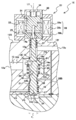
- the electromagnetic pressure regulating valve 1 configured as described above is guided from the high pressure tank 3 to the valve space 12e by the taper portion 14b of the valve body 14 and the upper surface of the flange 14e (pressure receiving surface P1 corresponding to the first pressure receiving surface). and receiving the primary pressure p 1 in the open position direction, the lower surface of the flange 14e (pressure receiving surface P2 corresponding to the second pressure receiving surface), and receiving the primary pressure p 1 in the closed position.
- the pressure receiving surface P1 is a region radially outward from the secondary region 12g in the tapered surface in plan view. In each pressure receiving surface P1, P2, the primary pressure p 1 are acting in a direction against each other and cancel each other.
- the pressure receiving areas of the pressure receiving surfaces P1, P2 are substantially the same because the lower end 14d side of the flange 14e of the valve body 14 and the inner diameter (that is, the seat diameter) of the secondary side region 12g have substantially the same outer diameter. It has become. Therefore, to prevent the action force by the primary pressure p 1 received by the pressure receiving surface P1, and the acting force by the primary pressure p 1 received by the pressure receiving surface P2 are canceled with each other, the effects of changes in primary pressure p 1 in the valve body 14 Can do.
- electromagnetic pressure regulating valve 1 is to pressure the secondary pressure p 2 flowing secondary side area 12g in the tapered surface of the distal end and the tapered portion 14b of the valve body 14 (pressure receiving surface P3) in the open position direction, the diaphragm seal 19 and secondary pressure p 2 guided to the pressure feedback chamber 24 at the lower end 14d (pressure receiving surface P4) of the valve body 14 receives the pressure in the closed position.
- the pressure receiving surface P4 is a region that overlaps the secondary region 12g in plan view. Further, the pressure-receiving surface P3, P4, secondary pressure p 2 is acting in a direction against each other.
- valve body 14 has substantially the same outer diameter r 2 and seat diameter r 1, and the effective diameter r 3 of the diaphragm seal 19 is larger than the outer diameter r 2 of the seat diameter r 1 and the valve body 14 .
- an amount corresponding pressure receiving area of the effective area of it is diaphragm seal 19 of the pressure receiving surface P4 for receiving the secondary pressure p 2 in the closed position direction compared to the pressure receiving surface P3 of receiving the secondary pressure p 2 in the open position direction Is getting bigger.
- valve body 14 acting force by the secondary pressure p 2 received by the pressure receiving surface P3, P4 is not completely canceled, the action force corresponding to the difference between the pressure receiving areas of each pressure receiving surface P3, P4 is closed Acts in the direction of the position.
- the valve body 14 is urged by the return spring 26 in the closed position direction and is seated on the seat portion 15.
- the electromagnetic pressure regulating valve 1 is configured as a normally closed valve. Accordingly, the valve passage 13 can be urgently cut off by cutting off the current flowing through the solenoid coil 28.
- the fuel gas in the secondary side region 12g is discharged from the secondary port 12c through the secondary side passage 12f and led to the pressure feedback chamber 24 through the pressure equalizing passage 25.
- the diaphragm seal 19 receives the secondary pressure p 2 of the fuel gas guided to the pressure feedback chamber 24.
- the valve body 14 is moved excitation force movable member 31 receives, at the pressure receiving surface P3, P4 acting force by each receiving secondary pressure p 2, and to a position where the spring forces are balanced in the return spring 26. That is, the opening degree of the valve passage 13 so that the force is balanced (i.e., opening degree of the orifice) for adjusting the secondary pressure p 2 of the fuel gas to adjust the flows in the secondary side area 12g.
- the pressure secondary pressure p 2 is corresponding to the current supplied to the solenoid coil 28 (i.e., the target pressure).
- the electromagnetic pressure regulating valve 1 can control the opening degree of the valve passage 13 according to the fluctuation, and can regulate the secondary pressure p 2 to the target pressure. Therefore, even if the primary pressure p 1 is not reduced to a constant pressure in advance, the high pressure fuel gas can be reduced to a low target pressure by the electromagnetic pressure regulating valve 1 alone. Therefore, the electromagnetic pressure regulating valve 1 has high pressure controllability.
- the electromagnetic pressure regulating valve 1 since the pressure receiving area of the pressure receiving surface P1 and the pressure receiving surface P2 substantially the same, are canceled acting force the valve body 14 receives from the primary pressure p 1.
- the secondary pressure p 2 can be accurately controlled than traditional electromagnetic pressure regulating valve.
- the fuel in the electromagnetic pressure regulating valve 1 since the pressure difference between the primary pressure p 1 and the secondary pressure p 2 is greater, when the valve body 14 is moved to the buffer chamber 22 from the valve space 12e in a high pressure sealing member 20 May leak slightly into the gas.
- the low-pressure seal member 21 is disposed in the bearing member housing space 17 side of the high-pressure seal member 20 even if the fuel gas leaks from the high-pressure seal member 20, the electromagnetic pressure regulating valve 1 is supported by the low-pressure seal member 21. The fuel gas does not leak into the member accommodating space 17.
- the buffer chamber 22 is connected to the pressure return chamber 24, the secondary side region 12g, and the like through the pressure equalizing passage 25, and a safety structure is provided to return the fuel gas leaked by the high pressure seal member 20 to the secondary side. ing. Therefore, the fuel gas leaking from the high pressure seal member 20 is not released to the outside of the electromagnetic pressure regulating valve 1. That is, fuel gas does not leak into the atmosphere.
- the diaphragm seal 19 it is possible to eliminate sliding friction when the valve body 14 is moved. Further, by adopting the low-pressure seal member 21 having a low frictional resistance, sliding friction can be suppressed as much as possible. Thus, the valve body 14 can be smoothly moved by suppressing the sliding friction which acts on the valve body 14. As a result, the secondary pressure can be quickly adjusted to the target pressure, and the response of the secondary pressure is improved. Further, by adopting the high-pressure sealing member 20, it is possible to pressure resistance is improved with respect to the primary pressure p 1 of the electromagnetic pressure regulating valve 1, to improve the critical pressure of the primary pressure supplied from the primary port 12a.
- the two valves 1 and 7 having a shut-off function are connected between the high-pressure tank 3 and the fuel gas consumer. Can be cut off. Thereby, the safety
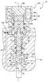
- the electromagnetic pressure regulating valve 1A according to the second embodiment of the present invention is similar in configuration to the electromagnetic pressure regulating valve 1 according to the first embodiment. Therefore, only the configuration different from that of the electromagnetic pressure regulating valve 1 of the first embodiment will be described with respect to the configuration of the electromagnetic pressure regulating valve 1A according to the second embodiment, and the same components are denoted by the same reference numerals and description thereof is omitted. To do. The same applies to the third and subsequent embodiments.
- the electromagnetic pressure regulating valve 1A has a pressure feedback passage 35 in the housing 12A as shown in FIG.
- the pressure feedback passage 35 is formed so as to connect the secondary side passage 12 f of the valve passage 13 and the pressure feedback chamber 24, and guides the secondary pressure p 2 to the pressure feedback chamber 24. Further, in the valve body 14A, the opening on the lower side (that is, the pressure feedback chamber side) of the feedback chamber side communication portion 25a of the pressure equalizing passage 25A is closed, and the buffer chamber 22 is connected only to the secondary region 12g. Yes.
- the electromagnetic pressure regulating valve 1A according to the second embodiment configured as described above has the same effects as the electromagnetic pressure regulating valve 1 according to the first embodiment.
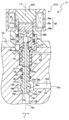
- the electromagnetic pressure regulating valve 1B has a valve body 14B as shown in FIG.
- a circumferential groove 36 that is recessed inward in the radial direction is formed between the high pressure seal member 20 and the low pressure seal member 21.
- the circumferential groove 36 is formed on the entire outer periphery of the valve body 14B, and forms a buffer chamber 22B between the high pressure seal member 20 and the low pressure seal member 21 together with the inner peripheral surface of the housing 12B.
- a pressure return passage 35B is formed in the housing 12B.
- the pressure feedback passage 35B connects the secondary side passage 12f and the pressure feedback chamber 24, and also connects the secondary side passage 12f and the buffer chamber 22B.
- the pressure feedback chamber 24 can lead to secondary pressure p 2 by the pressure feedback passage 35B, the fuel gas leaked into the buffer chamber 22 can be returned to the secondary side.
- the electromagnetic pressure regulating valve 1B according to the third embodiment configured as described above has the same effects as the electromagnetic pressure regulating valve 1 according to the first embodiment.
- the electromagnetic pressure regulating valves 1C to 1E according to the fourth to sixth embodiments of the present invention are similar to the electromagnetic pressure regulating valves 1, 1A and 1B according to the first to third embodiments, respectively.
- the electromagnetic pressure regulating valves 1C to 1E according to the fourth to sixth embodiments are different from the electromagnetic pressure regulating valves 1, 1A, 1B according to the first to third embodiments, respectively. Only the different points will be described below, and the description of the same configuration will be omitted.
- the electromagnetic pressure regulating valves 1C to 1E respectively have valve bodies 14C to 14E as shown in FIGS.
- the tip end portion 14a extends to the vicinity of the openings of the housings 12, 12A, 12B.
- a bearing member 37 is externally mounted on the distal end portion 14a of the valve bodies 14C to 14E.
- the bearing member 37 has a substantially cylindrical shape, and is constituted by, for example, a ball guide, a ball bearing, or a slide bearing.
- the bearing member 37 is interposed between the distal end portion 14a and the housing 12, and supports the valve bodies 14C to 14E. As a result, the valve bodies 14C to E can move smoothly in the vertical direction.
- the upper and lower ends of the valve bodies 14C to 14E are supported by the bearing members 18 and 37, respectively. Since 14E can be moved with high accuracy, the pressure controllability can be further improved.
- the electromagnetic pressure regulating valves 1C to 1E according to the fourth to sixth embodiments exhibit the same functions and effects as the electromagnetic pressure regulating valves 1, 1A, 1B according to the fourth to sixth embodiments, respectively.
- the distal end portion 14a of the valve body 14F extends to the vicinity of the opening of the housing 12, and the distal end portion of the pressing member 33F extends to the distal end portion 14a.
- the parts are joined by screwing.
- a diaphragm seal 19F is provided near the opening of the housing 12F.
- the outer edge portion of the diaphragm seal 19F is attached to the housing 12F, and the inner edge portion is attached to the valve body 14F.
- the outer edge portion of the diaphragm seal 19F is sandwiched between the respective parts of the housing 12F that is divided into two in the vertical direction, and the inner edge portion is sandwiched between the pressing member 33F and the valve body 14. Yes.
- the vicinity of the opening of the housing 12F where the diaphragm seal 19F is provided has an inner diameter larger than the inner diameter of the secondary region 12g and forms a pressure feedback chamber 24F.
- the pressure feedback chamber 24F is located between the secondary region 12g and the inner space 27a of the electromagnetic proportional solenoid 27.
- a diaphragm seal 19F is located between the pressure feedback chamber 24F and the inner space (space in the electromagnetic proportional solenoid 27) 27a of the electromagnetic proportional solenoid 27, and the diaphragm seal 19F is closed between them. ing. Since the pressure feedback chamber 24F is on the electromagnetic proportional solenoid 27 side, the pressure equalizing passage 25F is configured to connect the secondary region 12g and the buffer chamber 22.
- Electromagnetic pressure regulating valve 1F thus constituted in accordance with the seventh embodiment, similarly to the electromagnetic pressure regulating valve 1, 1A ⁇ 1E according to another embodiment, the closed position the secondary pressure p 2 in the diaphragm seal 19F Taking in the direction.
- the effective pressure receiving area of the diaphragm seal 19F is larger than the pressure receiving area of the pressure receiving surface P4 of the valve body 14F. Therefore, the opening degree of the valve passage 13 adjusted, it is possible to control the secondary pressure p 2 at the target pressure in accordance with the secondary pressure p 2.
- the electromagnetic proportional solenoid 27 can be disposed in the atmosphere. Since the electromagnetic proportional solenoid 27 can be arranged in the atmosphere as described above, when a corrosive fluid such as hydrogen gas is used as the fuel gas, the components of the electromagnetic proportional solenoid 27 are prevented from being exposed to the corrosive fluid. Can do. Therefore, corrosion of each component can be prevented.
- the electromagnetic pressure regulating valve 1F according to the seventh embodiment has the same effects as the electromagnetic pressure regulating valve 1 according to the seventh embodiment.
- a valve body hole 12b is formed in the housing 12G along the axis L1, and a secondary region 12g is formed below the valve space 12e.
- the housing 12G has a seat portion 15G in the vicinity of the opening on the valve space 12e side in the secondary side region 12g, and the seat portion 15G is formed so as to surround the periphery of the opening.
- a valve body 14G is inserted into the valve body hole 12b of the housing 12G along the axis L1.
- the valve body 14G has a tapered portion 14b that tapers downward toward the lower end side thereof, and is seated on the seat portion 15G in a state where the tip end portion of the tapered portion 14b projects into the secondary region 12g. ing.
- the housing 12G has a bearing member accommodating space 17 above the valve space 12e, and a seal mounting portion 16 therebetween.
- the high pressure seal member 20 is provided on the seal space 16e on the valve space 12e side
- the low pressure seal member 21 is provided on the bearing member accommodation space 17 side.
- a buffer chamber 22 is formed between the high pressure seal member 20 and the low pressure seal member 21.
- a substantially cylindrical bearing member 18 is accommodated in the bearing member accommodating space 17 in a state of being covered by the valve body 14G.
- the bearing member 18 is interposed between the housing 12G and the valve body 14G and supports the valve body 14G. Thereby, the valve body 14G can move smoothly in the vertical direction.
- an electromagnetic proportional solenoid 27G is screwed and fixed to the outer periphery of the opening end of the housing 12G.
- the electromagnetic proportional solenoid 27G has a solenoid coil 28 and a fixed magnetic pole 29G.
- the fixed magnetic pole 29G is provided so as to block the upper opening of the solenoid coil 28.
- a movable member 31G is provided in the solenoid coil 28.
- the movable member 31G is a substantially cylindrical member made of a magnetic material. The upper end of the movable member 31G faces the fixed magnetic pole 29G, and the lower end thereof is inserted into the valve element hole 12b of the housing 12G.
- An annular guide member 32 made of a non-magnetic material is interposed between the movable member 31G and the solenoid coil 28.
- the lower end of the movable member 31G reaches the upper end portion of the valve body 14G, and the upper end portion of the valve body 14G is screwed to and fixed to the lower end thereof.
- valve body hole 12b of the housing 12G has a large diameter between the opening end portion and the bearing member accommodating space 17 like the valve space 12e, and a diaphragm seal 19G is provided there. .
- the diaphragm seal 19G is located above the bearing member accommodating space 17, and has an outer edge attached to the housing 12G and an inner edge attached to the valve body 14G. More specifically, the outer edge portion of the diaphragm seal 19G is sandwiched between the respective parts of the housing 12G that is divided into two in the vertical direction, and the inner edge portion is sandwiched between the movable member 31G and the valve body 14G. Yes.
- the region above the diaphragm seal 19G in the valve body hole 12b of the housing 12G becomes the pressure feedback chamber 24G.
- a pressure feedback passage 35G is formed in the housing 12G, and the pressure feedback chamber 24G and the secondary side region 12g are connected by the pressure feedback passage 35G.
- the secondary pressure p 2 is guided to the pressure feedback chamber 24G.
- the movable member 31G has a flange 31a on the outer peripheral surface on the lower end side.
- the flange 31a protrudes outward in the radial direction and is formed over the entire circumference in the circumferential direction.
- the housing 12G has a receiving portion 12h at a position facing the upper surface of the flange 31a.
- a return spring 26G is disposed between the receiving portion 12h and the flange 31a.
- the return spring 26G is a so-called compression coil spring, and is externally attached to the movable member 31G in a compressed state, and urges the valve body 14G in the closed position direction via the movable member 31G.
- a current is passed through the electromagnetic proportional solenoid 27, an exciting force in a direction against the spring force of the return spring 26G (that is, the open position direction) acts on the movable member 31.
- the upper side (except for the portion screwed to the movable member 31G) of the valve body 14G has the same outer shape as the seat diameter. Yes. Therefore, the pressure receiving areas of the pressure receiving surface P1 (the upper surface of the flange 14e) and the pressure receiving surface P2 (the tapered surface of the tapered portion 14b) are substantially the same. Therefore, the acting force due to the primary pressure p 1 received by the valve body 14G on the pressure receiving surface P1 and the pressure receiving surface P2 is canceled out, and the influence due to the fluctuation of the primary pressure p 1 in the valve body 14 can be prevented.
- the pressure receiving area of the pressure receiving surface P3 is larger than the pressure receiving area of the pressure receiving surface P4 by the effective pressure receiving area of the diaphragm seal 19G.
- the acting force received respectively in a direction against each other in the closed position direction and a closed position direction by the secondary pressure p 2, although the action force acts so cancel each other
- the acting force corresponding to the difference in pressure receiving area between the pressure receiving surfaces P3 and P4 acts on the valve body 14G.
- the valve element 14 is biased to a closed position direction return spring 26G. Therefore, the electromagnetic pressure regulating valve 1G is configured as a normally closed valve.
- the electromagnetic pressure regulating valve 1G according to the eighth embodiment configured as described above is configured to pull up the valve body 14G upward to move the valve body 14G in the closed position direction when a current is passed through the solenoid coil 28. it is except for (ie, a is an electromagnetic pressure regulating valve pull) point, it is possible to pressure regulate the secondary pressure p 2 to the target pressure in the same operation as electromagnetic pressure regulating valve 1 of the first embodiment. Moreover, the electromagnetic pressure regulating valve 1G according to the eighth embodiment has the same effects as the electromagnetic pressure regulating valve 1 according to the first embodiment.
- the electromagnetic pressure regulating valve 1H according to the ninth embodiment of the present invention is similar in configuration to the electromagnetic pressure regulating valve 1G according to the eighth embodiment. Therefore, only the configuration different from the electromagnetic pressure regulating valve 1 of the first embodiment will be described with respect to the configuration of the electromagnetic pressure regulating valve 1G according to the ninth embodiment, and the same configuration will be denoted by the same reference numerals and the description thereof will be omitted. To do. The same applies to the tenth embodiment.
- the electromagnetic pressure regulating valve 1H has a valve body 14H as shown in FIG.
- a circumferential groove 36H that is recessed radially inward is formed between the high pressure seal member 20 and the low pressure seal member 21.
- the circumferential groove 36H is formed on the entire outer periphery of the valve body 14H, and forms a buffer chamber 22H between the high pressure seal member 20 and the low pressure seal member 21 together with the inner peripheral surface of the housing 12H.
- the buffer chamber 22H is connected to the pressure feedback passage 35H, and the fuel gas leaking into the buffer chamber 22 is returned to the secondary side such as the pressure feedback chamber 24G and the secondary region 12g via the pressure feedback passage 35H. .
- the electromagnetic pressure regulating valve 1H according to the ninth embodiment configured as described above has the same effects as the electromagnetic pressure regulating valve 1G according to the eighth embodiment.
- a pressure equalizing passage 25J is formed in the valve body 14J as shown in FIG.
- the pressure equalizing passage 25J has a communication portion 25d and a feedback portion 25e.
- the communication portion 25d penetrates from the lower end to the upper end along the axis L1 of the valve body 14J, and the feedback portion 25e extends in the radial direction and connects the buffer chamber 22 and the communication portion 25d.
- a communication chamber 31b is formed in the movable member 31J.
- the communication chamber 31b communicates with the pressure equalizing passage 25J and is connected to the pressure feedback chamber 24G by a communication passage 31c formed in the movable member 31J.
- Electromagnetic pressure regulating valve 1J thus constituted in accordance with the tenth embodiment, the pressure equalizing passage 25 J, communicating chamber 31b and the communication passage 31c of the secondary side area 12g via the secondary pressure p 2 is the pressure feedback chamber 24G Led to.
- the fuel gas leaking into the buffer chamber 22G is returned to the secondary side such as the pressure feedback chamber 24G and the secondary region 12g via the pressure equalizing passage 25J.
- the electromagnetic pressure regulating valve 1J according to the tenth embodiment configured as described above has the same effects as the electromagnetic pressure regulating valve 1G according to the eighth embodiment.
- the electromagnetic pressure regulating valves 1K to 1N according to the eleventh to fourteenth embodiments are similar to the electromagnetic pressure regulating valves 1 and 1A to 1C according to the first to fourth embodiments, respectively, but are shown in FIGS. Thus, it differs from the electromagnetic pressure regulating valves 1 and 1A to 1C according to the first to fourth embodiments in that the pressure receiving area A1 and the pressure receiving area A2 are different. This will be described in detail below.
- the outer diameter r 2 of the valve body 14 is smaller than the seat diameter r 1. Therefore, the pressure receiving area of the pressure receiving surface P1 is smaller than the pressure receiving area of the pressure receiving surface P2. Therefore, the acting force of the primary pressure p 1 according to the difference between the pressure receiving area of the pressure receiving surface P1 and the pressure receiving area of the pressure receiving surface P2 acts on the valve body 14 toward the closed position. Therefore, the speed toward the closed position of the valve bodies 14K to 14N when the current flowing through the solenoid coil 28 is interrupted is increased, and the interrupting performance is improved.
- the electromagnetic pressure regulating valves 1D to 1G can firmly close the valve passage 13 so that the fuel gas does not leak from the primary side to the secondary side.
- the electromagnetic pressure regulating valves 1K to 1N according to the eleventh to fourteenth embodiments have the same effects as the electromagnetic pressure regulating valve 1 according to the first embodiment.
- the pressure regulating valve 1O according to the fifteenth embodiment is similar to the electromagnetic pressure regulating valve 1 according to the first embodiment, and includes a piezoelectric actuator 27O instead of the electromagnetic proportional solenoid 27 as shown in FIG.
- the piezoelectric actuator 27O as a valve body driving means is composed of a piezoelectric element (for example, a piezo element), generates a driving force according to an applied voltage, and moves the valve body 14 in the open position direction via the pressing member 33.
- the valve passage 13 is opened by moving.
- electromagnetic pressure regulating valve 1O also pressure regulating the secondary pressure p 2 in the pressure corresponding to the voltage applied to the piezoelectric actuator 27O It can be done.
- the pressure regulating valve 1O according to the fifteenth embodiment has the same configuration as the electromagnetic pressure regulating valve 1 according to the first embodiment, and has the same operational effects.
- the pressure regulating valve 1P according to the sixteenth embodiment is similar to the electromagnetic pressure regulating valve 1 according to the first embodiment, and includes a force motor 27P instead of the electromagnetic proportional solenoid 27 as shown in FIG.
- a force motor 27P instead of the electromagnetic proportional solenoid 27 as shown in FIG.
- a movable coil 62 is inserted into a cylindrical permanent magnet 61.
- an excitation force corresponding to the current is generated.
- 63 is moved downward.
- the valve body 14 is pushed toward the open position by the pressing member 33 provided integrally therewith, and the valve passage 13 is opened.
- the valve passages 13, open in opening corresponding to the excitation force generated, regulating valve 1P also made it possible to pressure regulate the secondary pressure p 2 in the pressure corresponding to current flowing in the force motor 27P Yes.
- the pressure regulating valve 1P according to the sixteenth embodiment has the same configuration as the electromagnetic pressure regulating valve 1 according to the first embodiment, and has the same operational effects.
- the pressure regulating valve 1Q according to the seventeenth embodiment is similar to the electromagnetic pressure regulating valve 1G according to the eighth embodiment, and includes a piezoelectric actuator 27Q instead of the electromagnetic proportional solenoid 27G as shown in FIG.
- the piezoelectric actuator 27Q applies a voltage to contract a piezoelectric element 27a (for example, a piezo element), thereby opening the valve body 14 in an opening position direction via a movable member 31Q provided integrally with the piezoelectric element 27a (see FIG.
- the valve passage 13 is opened by being moved upward.
- the valve passages 13, open in opening corresponding to the driving force generated, regulating valve 1Q also allow pressure regulation of the secondary pressure p 2 in the pressure corresponding to the voltage applied to the piezoelectric actuator 27Q It has become.
- the pressure regulating valve 1Q according to the seventeenth embodiment has the same configuration as the electromagnetic pressure regulating valve 1G according to the eighth embodiment, and has the same operational effects.
- the pressure regulating valve 1R according to the eighteenth embodiment is similar to the electromagnetic pressure regulating valve 1G according to the eighth embodiment, and includes a force motor 27R instead of the electromagnetic proportional solenoid 27G as shown in FIG.
- a movable member 31R is integrally provided in the movable coil 62 of the force motor 27R, and when the movable coil 62 is moved by passing an electric current through the movable coil 62, the valve body 14 moves in the open position direction and the valve is moved.
- the passage 13 opens.
- the valve passages 13, open in opening corresponding to the excitation force generated, regulating valve 1R is also adapted to be pressure adjusted secondary pressure p 2 in the pressure corresponding to current flowing in the force motor 27R Yes.
- the pressure regulating valve 1R according to the eighteenth embodiment has the same configuration as the electromagnetic pressure regulating valve 1G according to the eighth embodiment, and has the same operational effects.
- the electromagnetic pressure regulating valve 1S according to the nineteenth embodiment is similar to the electromagnetic pressure regulating valve 1G according to the eighth embodiment.
- the shape of the valve seat portion 15S and the distal end portion of the valve body 14S are mainly used.
- the shape of 14a and the position of the return spring 26S are different.
- the valve seat portion 15S is formed along the outer edge so as to surround the vicinity of the valve port 10 which is an opening connecting the secondary side passage 12f and the valve space 12e.
- the valve seat portion 15S protrudes upward, and forms a valve seat surface 15a at the top portion of the valve seat portion 15S.
- the valve seat surface 15a is orthogonal to the axis L1.
- valve body 14S is positioned in the valve body hole 12b of the housing 12G with its front end portion 14a facing the valve seat portion 15S, and the front end portion 14a is moved by the valve body 14S moving downward to be in the closed position. Is seated on the valve seat portion 15S, and conversely, the valve body 14S moves upward and is positioned at the open position, so that the tip portion 14a is separated from the valve seat portion 15S as shown in FIG. Moreover, the valve body 14S has the pressure regulation sheet
- Pressure regulating sheet member 11 is a member of generally disc shape made of rubber or resin, its outer diameter is made the diameter of the valve seat portion 15S, i.e. the seat diameter r 1 to a larger diameter.
- the pressure adjusting sheet member 11 is disposed so as to face the valve seat portion 15S, and the valve body surface 11a seated on the valve seat surface 15a of the valve seat portion 15S is formed so as to be orthogonal to the axis L1. In other words, the pressure adjusting sheet member 11 of the valve body 14S comes into contact with the valve seat surface 15a perpendicularly.
- the distal end portion 14a of the valve body 14S is formed to have a larger diameter than the remaining portion, and the distal end portion 14a has a flange 14e on the outer peripheral portion.
- the flange 14e projects outward in the radial direction and extends over the entire circumference in the circumferential direction.
- the upper surface of the flange 14e faces the ceiling surface that defines the valve space 12e, and a return spring 26S is provided between the upper surface of the flange 14e and the ceiling surface.
- the return spring 26S is a so-called compression coil spring, and is externally attached to the valve body 14S in a compressed state, and urges the valve body 14S downward in the closed position direction. By being urged, the distal end portion 14a of the valve body 14S is seated on the valve seat portion 15S and closes the valve passage 13.
- the pressure feedback passage 35 formed in the housing 12G returns the fuel gas leaked to the buffer chamber 22 to the secondary region such as the pressure feedback chamber 24G and the secondary passage 12f via the pressure feedback passage 35.
- the electromagnetic pressure regulating valve 1S is a safety structure valve that can return the fuel gas leaked from the primary region such as the valve space 12e to the secondary region without leaking outside.
- the primary pressure p 1 is reduced to the secondary pressure p 2 by the annular orifice 38 formed between the valve seat portion 15S and the valve body 14S. depressurized secondary pressure p 2 is guided to the secondary port 12c via the secondary passage 12f.
- valve 14S is to pressure the secondary pressure p 2 in the region inside the orifice 38 of the tip portion 14a (pressure receiving surface P3) in the open position direction, the upper surface of the diaphragm seal 19G and proximal end face of the valve body 14S (the pressure-receiving surface P4) in the secondary pressure p 2 has been receiving in the closed position direction, these in two pressure-receiving surface P3, P4, and a pressure receiving in direction against each other secondary pressure p 2 ing.
- the solenoid type adjusting valve 1S it is larger than the effective diameter r 3 of the diaphragm seal 19G seat diameter r 1 (diameter substantially coincides orifice 38), the pressure receiving surface P4 than the pressure receiving area A3 of the pressure receiving surface P3 The pressure receiving area A4 is larger. Therefore, the acting force according to the difference between the pressure receiving areas A3 and A4 of the two pressure receiving surfaces P3 and P4 acts on the valve body 14S in the closed position direction, and the electromagnetic pressure regulating valve 1S is the same as that of the eighth embodiment. Similar to the electromagnetic pressure regulating valve 1G, it is configured as a normally closed valve.
- the pressure receiving area of the pressure receiving surface P1, P2 are substantially coincident, the primary pressure p 1 in which the valve body 14S to pressure is canceled. Since the operation of the electromagnetic pressure regulating valve 1S is substantially the same as the operation of the electromagnetic pressure regulating valve 1G of the eighth embodiment, the description of the operation is omitted. The same applies to the twentieth to twenty-second embodiments described below.
- the valve seat surface 15a of the valve seat portion 15S and the valve body surface 11a of the valve body 14S are both orthogonal to the axis L1, that is, orthogonal to the open position direction.
- the valve seat 15S or the pressure regulating seat member 11 is plastically deformed in the open position direction by repeated use. Therefore, almost without seat diameter r 1 is changed even if the plastic deformation, repeated hardly changes tone pressure characteristics be used. Therefore, the reliability of the electromagnetic pressure regulation valve 1S and the stability of the pressure regulation characteristics can be improved.
- the electromagnetic pressure regulating valve 1S has a pull-type structure that can lift the valve body 14S by the electromagnetic proportional solenoid 27G and move it in the open position direction, like the electromagnetic pressure regulating valve 1G of the eighth embodiment. Therefore, the electromagnetic proportional solenoid 27 ⁇ / b> G can be disposed outside the valve passage 13.
- the secondary side passage 11f is the same as the electromagnetic pressure regulating valve having a push type structure in which the electromagnetic proportional solenoid 27G is disposed in the secondary side passage 12f and the valve body 14S is pushed in the open position direction.
- the diameter of the orifice 38 (that is, the seat diameter r1) can be made smaller than that of the electromagnetic pressure regulating valve having the push type structure.
- the opening change amount of the valve passage 13 with respect to the change of the stroke of the valve body 14S by reducing the seat diameter r 1 is reduced, the opening of the valve passage 13 than gas electromagnetic pressure regulating valve push structure It is possible to finely adjust the degree, and the stability and pressure adjustment accuracy of the electromagnetic pressure regulating valve 1S can be improved.
- valve body 14S is a moving member, the seating position varies, but the valve body surface 11a of the valve body 14S is seated on the valve body surface 11a by the protruding valve seat portion 15S from the valve seat portion 15S. By making it wide, the valve body 14S can be reliably seated on the valve seat portion 15S even if there is some variation in the seating position. Further, since the valve seat portion 15S is formed along the outer edge of the valve port 10, the inner diameter dimension of the valve port 10 and the inner diameter dimension of the valve seat portion 15S are substantially the same, and a necessary flow path area is ensured. it is possible to reduce the sheet size r 1 while. Thereby, the stability of the pressure regulation accuracy of the electromagnetic pressure regulating valve 1S can be improved.
- a protrusion may be provided on the valve body surface 11a side of the valve body 14S of the electromagnetic pressure regulating valve 1S, that is, a protrusion may be provided at the tip of the valve body 14S.
- the valve port 10 is closed when the protruding portion is seated on a position deviated from a predetermined seating position, for example, on the valve port 10. It is assumed that this is not possible. Therefore, it is necessary to make the inner diameter dimension of the protruding portion larger than the inner diameter dimension of the valve port 10 so that the valve port 10 can be reliably closed.
- the electromagnetic pressure regulating valve 1S according to the nineteenth embodiment has the same effects as the electromagnetic pressure regulating valve 1G according to the eighth embodiment.
- the electromagnetic pressure regulating valve 1T according to the twentieth embodiment of the present invention is similar in configuration to the electromagnetic pressure regulating valve 1S according to the nineteenth embodiment, and only differs from the electromagnetic pressure regulating valve 1S according to the nineteenth embodiment. explain. And about the same structure, the same code
- the pressure equalizing passage 25J is formed in the valve body 14T in the same manner as the valve body 14 of the electromagnetic pressure regulating valve 1J according to the tenth embodiment. Is formed.
- the pressure equalizing path are connected and the second-side passage 12f and the pressure feedback chamber 24G by 25 J, so that the secondary pressure p 2 is guided to the pressure feedback chamber 24G.
- the electromagnetic pressure regulating valve 1T like the electromagnetic pressure regulating valve 1S of the nineteenth embodiment, the secondary pressure p 2 in the pressure feedback chamber 24G by pressure diaphragm seal 19G, in response to the secondary pressure p 2 opening is pressed is adjusted secondary pressure p 2 is tone valve passage 13.
- the pressure adjusting sheet member 11T is formed in a generally annular shape, surrounds the lower opening of the pressure equalizing passage 25J (that is, the opening facing the secondary passage 12f), and is positioned slightly away from the outer edge of the opening. is doing.
- the buffer chamber 22 is connected to the secondary side passage 11f by the pressure equalizing passage 25J, and the fuel gas leaked into the buffer chamber 22 is returned to the secondary side passage 11f.
- the electromagnetic pressure regulating valve 1T is also a valve having a safety structure for returning the fuel gas leaked from the high pressure seal member 20 to the secondary side.
- the electromagnetic pressure regulating valve 1T according to the twentieth embodiment configured as described above has the same effects as the electromagnetic pressure regulating valve 1S according to the nineteenth embodiment.
- the movable member 31U has a flange 31a on the outer peripheral surface portion thereof as in the electromagnetic pressure regulating valve 1G of the eighth embodiment (see FIG. 22).
- a return spring 26U is provided between the flange 31a and the spring seat 12h of the housing 12 at a position facing the flange 31a.
- the return spring 26U is interposed between the spring seat 12h and the flange 31a in a compressed state, and urges the valve body 14U in the closed position direction via the movable member 31U.
- the electromagnetic pressure regulating valve 1U according to the twenty-first embodiment configured as described above has the same effects as the electromagnetic pressure regulating valve 1S according to the nineteenth embodiment.
- the acting force by the primary pressure p 1 is acting toward the closed position, the sealing surface pressure of the seating portion is increased between the valve body 14V and the valve seat portion 15S, the electromagnetic proportional solenoid 27G When not operating, the valve body 14V is held in the closed position. Therefore, the valve passage 13 can be closed firmly, and the airtightness when seated is improved.
- the electromagnetic pressure regulating valve 1V according to the twenty-second embodiment has the same effects as the electromagnetic pressure regulating valve 1S according to the nineteenth embodiment.
- the secondary pressure p 2 in the pressure feedback chamber 24 is pressure in the diaphragm seal 19 may not necessarily be a diaphragm seal may be a low-pressure sealing member such as an O-ring.
- the outer diameter r 2 of each of the valve 14S-14 V is substantially uniformly except for portions that are screwed to the flange 14e and the movable member 31G going on, or may be the outside diameter of the portion to be supported by the bearing member 18 larger than the outer diameter r 2.
- the inner diameter of the bearing member 18 can be increased, so that the linear motion performance of the valve bodies 14S to 14V can be improved, and variations in the seating positions of the valve bodies 14S to 14V can be reduced. The same applies to other embodiments.
- the seal diameters of the low-pressure seal member 20 and the high-pressure seal member 21 are substantially the same, but it is not always necessary to have the same seal diameter.
- the seal diameter of the low pressure seal member 21 larger than the seal diameter of the high pressure seal member 20
- the base end portions of the valve bodies 14S to 14V can be made thicker, and the rigidity of the valve bodies 14S to 14V can be improved. it can. Thereby, it can be set as a structure strong against a disturbance.
- the electromagnetic proportional solenoid 17 has been described as an example of the valve body driving means.
- the electromagnetic proportional solenoid is the same as the sixteenth to eighteenth embodiments.
- a piezoelectric element (piezo element) or a force motor may be employed instead of the solenoid 27G.
- the present invention can be applied to a gas pressure regulating valve that regulates the pressure of a high-pressure fuel gas to a pressure corresponding to an applied voltage or an applied current.
- Electromagnetic pressure regulating valve 1O to 1R Pressure regulating valve 2 Fuel gas supply system 12 Housing 12a Primary port 12c Secondary port 13 Valve passage 14, 14A to 14N, 14S to 14V Valve body 17 Bearing member accommodation Space 18 Bearing member 19, 19F, 19G Diaphragm seal 20 High pressure seal member 21 Low pressure seal member 22, 22B, 22G, 22H Buffer chamber 24, 24F, 24G Pressure feedback chamber 25, 25F, 25J Uniform pressure passage 26, 26G Return spring 27, 27G Electromagnetic proportional solenoid 27O, 27Q Piezoelectric actuator 27P, 27R Force motor
Abstract
Description
前記第2シール部材は、摩擦抵抗が小さい低圧シールであることが好ましい。
燃料ガス供給システム2は、水素ガスや圧縮天然ガス等の燃料ガスが高圧で貯蔵される高圧タンク3に設けられている。燃料ガス供給システム2は、燃料電池やガスエンジン等の燃料ガス消費器に繋がっており、高圧の燃料ガスを所望の低圧に調圧して燃料ガス消費器に供給するようになっている。このように構成される燃料ガス供給システム2は、容器元弁4、圧力センサ5、及び演算制御器6を備えている。容器元弁4は、オンタンク型で構成され、高圧タンク3の開口部に設けられている。なお、容器元弁4は、オンタンク型に限られず、インタンク形であってもよい。容器元弁4は、電磁式調圧弁1と電磁式遮断弁7とを有している。
<電磁式調圧弁の構成>
図2に示す第1実施形態の電磁式調圧弁1は、ハウジング12を備えている。ハウジング12は、高圧タンク3(図1参照)の開口部にシールを達成した状態で取付けられている。ハウジング12には、一次ポート12a、弁体孔12b、及び二次ポート12cが形成されている。一次ポート12aは、電磁式遮断弁7(図1参照)に繋がっており、ハウジング12に形成されている一次側通路12dを介して弁体孔12bに繋がっている。
以下では、図2を参照しながら電磁式調圧弁1の動作について説明する。ソレノイドコイル28に電流を流すと、可動部材31に励磁力(駆動力)が作用し、可動部材31がヨーク29の方へ吸引される。これにより、弁体14が押圧部材33によって開位置方向に押されて座部15から離れる。そうすると、弁通路13が開かれ、弁空間12eの燃料ガスが二次側領域12gへと流れる。この際、弁体14と座部15との間に形成されるオリフィス(図示せず)により弁空間12eから二次側領域12gに流れる燃料ガスが二次圧p2に減圧される。このように、電磁式調圧弁1は、ソレノイドコイル28に電流を流すと、弁体14が押圧部材33によって押されて弁通路が開くように構成されている(つまり、プッシュ型の電磁式調圧弁である)。
本発明の第2実施形態に係る電磁式調圧弁1Aは、第1実施形態に係る電磁式調圧弁1と構成が類似している。そこで、第2実施形態に係る電磁式調圧弁1Aの構成に関して第1実施形態の電磁式調圧弁1と異なる構成についてだけ説明し、同一の構成については、同一の符合を付して説明を省略する。第3実施形態以降についても同様である。
本発明の第3実施形態に係る電磁式調圧弁1Bは、図4に示すように弁体14Bを有している。弁体14Bは、高圧シール部材20及び低圧シール部材21との間に半径方向内方に凹む周回溝36が形成されている。周回溝36は、弁体14Bの外周に全周にわたって形成されており、ハウジング12Bの内周面と共に高圧シール部材20及び低圧シール部材21との間にバッファ室22Bを形成している。
本発明の第4~第6実施形態に係る電磁式調圧弁1C~1Eは、第1~第3実施形態に係る電磁式調圧弁1,1A,1Bに夫々類似している。第4~第6実施形態に係る電磁式調圧弁1C~1Eは、第1~第3実施形態に係る電磁式調圧弁1,1A,1Bと同じ点で夫々異なっている。以下では、その異なる点についてだけ説明し、同一の構成については説明を省略する。
第7実施形態に係る電磁式調圧弁1Fでは、図8に示すように、弁体14Fの先端部14aがハウジング12の開口付近まで延在しており、この先端部14aに押圧部材33Fの先端部が螺合により接合されている。また、ハウジング12Fの開口付近には、ダイアフラムシール19Fが設けられている。ダイアフラムシール19Fの外縁部は、ハウジング12Fに取付けられ、内縁部が弁体14Fに取付けられている。詳述すると、ダイアフラムシール19Fの外縁部は、上下に2つに分割されるハウジング12Fの各部位の間に挟まれ、また内縁部は、押圧部材33Fと弁体14との間に挟まれている。ダイアフラムシール19Fが設けられているハウジング12Fの開口付近は、二次側領域12gの内径より大きい内径を有しており、圧力帰還室24Fを形成している。この圧力帰還室24Fは、二次側領域12gと電磁比例ソレノイド27の内空間27aとの間に位置している。また、圧力帰還室24Fと電磁比例ソレノイド27の内空間(電磁比例ソレノイド27内の空間)27aとの間には、ダイアフラムシール19Fが位置しており、それらの間がダイアフラムシール19Fによって塞がれている。なお、圧力帰還室24Fが電磁比例ソレノイド27側にあるので、均圧通路25Fは、二次側領域12gとバッファ室22とを繋ぐように構成されている。
第8実施形態に係る電磁式調圧弁1Gは、図9に示すように、ハウジング12Gには、軸線L1に沿って弁体孔12bが形成され、弁空間12eの下側に二次側領域12gがある。また、ハウジング12Gは、二次側領域12gにおける弁空間12e側の開口付近に座部15Gを有しており、座部15Gは、その開口の周りを外囲するように形成されている。更に、ハウジング12Gの弁体孔12bには、軸線L1に沿って弁体14Gが挿入されている。弁体14Gは、その下端側に下方に向うにつれて先細りになっているテーパ部14bを有しており、テーパ部14bの先端部分を二次側領域12gに突っ込んだ状態で座部15Gに着座している。
本発明の第9実施形態に係る電磁式調圧弁1Hは、第8実施形態に係る電磁式調圧弁1Gと構成が類似している。そこで、第9実施形態に係る電磁式調圧弁1Gの構成に関して第1実施形態の電磁式調圧弁1と異なる構成についてだけ説明し、同一の構成については、同一の符合を付して説明を省略する。第10実施形態についても同様である。
第10実施形態に係る電磁式調圧弁1Jは、図11に示すように弁体14Jに均圧通路25Jが形成されている。均圧通路25Jは、連通部25dと、帰還部25eとを有している。連通部25dは、弁体14Jの軸線L1に沿って下端から上端まで貫通しており、帰還部25eは、半径方向に延在し、バッファ室22と連通部25dとを繋いでいる。また、可動部材31J内には、連絡室31bが形成されている。連絡室31bは、均圧通路25Jと連通しており、可動部材31Jに形成される連絡通路31cによって圧力帰還室24Gに繋がっている。
第11~14実施形態に係る電磁式調圧弁1K~1Nは、第1~第4実施形態に係る電磁式調圧弁1,1A~1Cと夫々類似しているが、図12~図15に示すように受圧面積A1及び受圧面積A2が異なっているという点で第1~第4実施形態に係る電磁式調圧弁1,1A~1Cと異なっている。以下では、その点について詳述する。
第15実施形態に係る調圧弁1Oは、第1実施形態の電磁式調圧弁1と類似しており、図16に示すように電磁比例ソレノイド27に代えて圧電アクチュエータ27Oを備えている。弁体駆動手段である圧電アクチュエータ27Oは、圧電素子(例えば、ピエゾ素子)から成り、印加される印加電圧に応じた駆動力を発生し、押圧部材33を介して弁体14を開位置方向に動かして弁通路13を開くようになっている。この際、弁通路13は、発生する駆動力に応じた開度で開き、電磁式調圧弁1Oもまた、圧電アクチュエータ27Oに印加される印加電圧に応じた圧力に二次圧p2を調圧できるようになっている。
第16実施形態に係る調圧弁1Pは、第1実施形態の電磁式調圧弁1と類似しており、図17に示すように電磁比例ソレノイド27に代えてフォースモータ27Pを備えている。フォースモータ27Pは、円筒状の永久磁石61の中に可動コイル62が挿入されており、可動コイル62に電流を流すと電流に応じた励磁力が発生し、この励磁力により可動コイル62がヨーク63内を下方に動くようになっている。可動コイル62が下方に動くことでそれに一体的に設けられている押圧部材33によって弁体14が開位置方向に押されて弁通路13が開く。この際、弁通路13は、発生する励磁力に応じた開度で開き、調圧弁1Pもまたフォースモータ27Pに流される電流に応じた圧力に二次圧p2を調圧できるようになっている。
第17実施形態の調圧弁1Qは、第8実施形態の電磁式調圧弁1Gと類似しており、図18に示すように電磁比例ソレノイド27Gに代えて圧電アクチュエータ27Qを備えている。圧電アクチュエータ27Qは、電圧を印加させて圧電素子27a(例えば、ピエゾ素子)を収縮させることで、圧電素子27aに一体的に設けられている可動部材31Qを介して弁体14を開位置方向(上方向)に移動させて弁通路13を開くようになっている。この際、弁通路13は、発生する駆動力に応じた開度で開き、調圧弁1Qもまた、圧電アクチュエータ27Qに印加される印加電圧に応じた圧力に二次圧p2を調圧できるようになっている。
第18実施形態の調圧弁1Rは、第8実施形態の電磁式調圧弁1Gと類似しており、図18に示すように電磁比例ソレノイド27Gに代えてフォースモータ27Rを備えている。フォースモータ27Rの可動コイル62には、可動部材31Rが一体的に設けられており、可動コイル62に電流を流して可動コイル62を移動させることで弁体14が開位置方向に移動して弁通路13が開くようになっている。この際、弁通路13は、発生する励磁力に応じた開度で開き、調圧弁1Rもまたフォースモータ27Rに流される電流に応じた圧力に二次圧p2を調圧できるようになっている。
第19実施形態の電磁式調圧弁1Sは、第8実施形態に係る電磁式調圧弁1Gと類似しており、図20に示すように主に弁座部15Sの形状、弁体14Sの先端部14aの形状、及び復帰用ばね26Sの位置が異なっている。弁座部15Sは、二次側通路12fと弁空間12eとを繋ぐ開口である弁口10付近を囲むようにその外縁に沿って形成されている。弁座部15Sは、上方に向かって突出しており、弁座部15Sの頂部分で弁座面15aを形成している。この弁座面15aは、軸線L1に直交している。
本発明の第20実施形態に係る電磁式調圧弁1Tは、第19実施形態に係る電磁式調圧弁1Sと構成が類似しており、第19実施形態の電磁式調圧弁1Sと異なる構成についてだけ説明する。そして、同一の構成については、同一の符合を付して説明を省略する。以下で説明する、第21及び第22実施形態についても同様である。
本発明の第21実施形態に係る電磁式調圧弁1Uでは、第8実施形態の電磁式調圧弁1Gと同様に可動部材31Uがその外周面部にフランジ31aを有しており(図22参照)、このフランジ31aとそれに対向する位置にあるハウジング12のばね受け座12hとの間に復帰用ばね26Uが設けられている。復帰用ばね26Uは、圧縮された状態でばね受け座12hとフランジ31aとの間に介在し、可動部材31Uを介して弁体14Uを閉位置方向に付勢している。
本発明の第22実施形態に係る電磁式調圧弁1Vでは、図23に示すように、弁体14Vの外径r2がシート径r1より小さくなっており、受圧面P1の受圧面積A1が受圧面P2の受圧面積より大きくなっている。それ故、2つの受圧面積A1,A2の差に応じた一次圧p1による作用力が閉位置に向かって作用する。
本実施形態では、圧力帰還室24の二次圧p2をダイアフラムシール19で受圧しているが、必ずしもダイアフラムシールでなくてもよく、Oリングなどの低圧シール部材であってもよい。
1O~1R 調圧弁
2 燃料ガス供給システム
12 ハウジング
12a 一次ポート
12c 二次ポート
13 弁通路
14,14A~14N,14S~14V 弁体
17 軸受部材収容空間
18 軸受部材
19,19F,19G ダイアフラムシール
20 高圧シール部材
21 低圧シール部材
22,22B,22G,22H バッファ室
24,24F,24G 圧力帰還室
25,25F,25J 均圧通路
26,26G 復帰用ばね
27,27G 電磁比例ソレノイド
27O,27Q 圧電アクチュエータ
27P,27R フォースモータ
Claims (14)
- 一次ポートと二次ポートとに繋がる弁通路を有するハウジングと、
前記ハウジング内に設けられ、前記弁通路を閉じる閉位置と前記弁通路を開く開位置との間で移動して前記弁通路の開度を調整する弁体と、
前記弁体を閉位置方向に付勢する復帰用ばねと、
印加される印加電圧又は印加電流に応じた駆動力を前記復帰用ばねの付勢に抗するように前記弁体に与えて前記弁体を前記開位置方向に移動させる弁体駆動手段とを備え、
前記一次ポートを介して前記弁通路に供給される高圧の燃料ガスの圧力を前記弁体駆動手段の駆動力に応じた圧力に調圧して前記二次ポートから出力するガス用調圧弁において、
前記ハウジング内に形成され、前記二次ポートに繋がる圧力帰還室と、
前記圧力帰還室の圧力を前記励磁力に抗する方向に受圧し、前記圧力帰還室の圧力に応じて前記弁体を前記閉位置へと移動させる第1シール部材と、
前記弁体と前記ハウジングとの間隙に介在し、前記弁体を摺動支持する軸受部材と、
前記軸受部材より前記弁通路側に設けられ、前記間隙を封止する第2シール部材と、
前記第2シール部材より更に前記弁通路側に設けられ、前記間隙を封止する第3シール部材と、を備え、
前記第3シール部材と前記第2シール部材との間には、前記二次ポートに繋がっているバッファ室が形成されている、ガス用調圧弁。 - 前記二次ポートと前記圧力帰還室とは、圧力帰還通路よって繋がっており、
前記圧力帰還通路は、前記弁体に形成されている、請求項1に記載のガス用調圧弁。 - 前記二次ポートと前記圧力帰還室とは、圧力帰還通路よって繋がっており、
前記圧力帰還通路は、前記ハウジングに形成されている、請求項1に記載のガス用調圧弁。 - 前記圧力帰還通路は、前記バッファ室にも繋がっている、請求項3又は4に記載のガス用調圧弁。
- 前記ハウジングは、前記弁体が前記閉位置に位置する際に着座する弁座部であって、前記開位置方向に対して直交する弁座面を備える弁座部を有し、
前記弁体は、前記開位置方向に直交する弁体面で前記弁座面に着座するようになっている、請求項1乃至4の何れか1つに記載のガス用調圧弁。 - 前記弁通路は、前記弁座部と前記弁体との間に形成されるオリフィスより下流側の二次ポートに繋がる二次側通路を有し、
前記弁体駆動手段は、前記二次側通路外であって前記弁体を挟んで前記弁座部と反対側の位置に設けられ、前記駆動力によって前記弁体を引き上げて前記開位置方向に移動させるようになっている、請求項5に記載のガス用調圧弁。 - 前記弁座部は、前記二次側通路において前記一次ポート側の開口である弁口の外縁に沿って形成され、前記弁体に向かって前記開位置方向に突出しており、
前記弁体は、前記弁座部に対向する位置にシート部材を有しており、
前記シート部材は、その一表面が前記弁体面を成し、その弁体面で前記弁座部の頂部に着座するようになっている、請求項6に記載のガス用調圧弁。 - 前記弁体は、前記一次ポートの一次圧を前記開位置の方に受圧する第1受圧面の受圧面積と前記一次圧を前記閉位置の方に受圧する第2受圧面の受圧面積とが同一になるように形成されている、請求項1乃至7の何れか1つに記載のガス用調圧弁。
- 前記弁体は、前記一次ポートの一次圧を前記開位置の方に受圧する第1受圧面の受圧面積が前記一次圧を前記閉位置の方に受圧する第2受圧面の受圧面積よりも小さくなるように形成されている、請求項1乃至7の何れか1つに記載のガス用調圧弁。
- 前記圧力帰還室は、前記軸受部材に対して前記第2シール部材と反対側に位置しており、
前記第1シール部材は、前記軸受部材と前記圧力帰還室との間に位置してそれらの間を塞いでいる、請求項1乃至9の何れか1つに記載のガス用調圧弁。 - 前記圧力帰還室は、前記弁通路と前記弁体駆動手段との間に位置しており、
前記第1シール部材は、前記弁体駆動手段と前記圧力帰還室との間に位置してそれらの間を塞いでいる、請求項1乃至10の何れか1つに記載のガス用調圧弁。 - 前記第1シール部材は、ダイアフラムシールであり、
前記第2シール部材は、摩擦抵抗が小さい低圧シールである、請求項1乃至11の何れか1つに記載のガス用調圧弁。 - 第3シール部材は、摩擦抵抗が小さく、さらに始動抵抗と摺動抵抗との差が小さい高圧シールである、請求項1乃至12の何れか1つに記載のガス用調圧弁。
- 前記弁体駆動手段に印加される印加電圧又は印加電流がゼロのときは、前記復帰用ばねにより前記弁体を前記閉位置にするノーマルクローズ形になっている、請求項1乃至13の何れか1つに記載のガス用調圧弁。
Priority Applications (6)
| Application Number | Priority Date | Filing Date | Title |
|---|---|---|---|
| JP2012527603A JP5427296B2 (ja) | 2010-08-06 | 2011-08-04 | ガス用調圧弁 |
| CA2806811A CA2806811C (en) | 2010-08-06 | 2011-08-04 | Gas pressure regulating valve |
| EP11814302.3A EP2602525B1 (en) | 2010-08-06 | 2011-08-04 | Pressure-regulating valve for gas |
| US13/812,017 US8960221B2 (en) | 2010-08-06 | 2011-08-04 | Gas pressure regulating valve |
| KR1020137004617A KR101455945B1 (ko) | 2010-08-06 | 2011-08-04 | 가스용 조압 밸브 |
| CN201180037248.XA CN103003605B (zh) | 2010-08-06 | 2011-08-04 | 气体用调压阀 |
Applications Claiming Priority (4)
| Application Number | Priority Date | Filing Date | Title |
|---|---|---|---|
| JP2010177868 | 2010-08-06 | ||
| JP2010-177868 | 2010-08-06 | ||
| JP2011063087 | 2011-03-22 | ||
| JP2011-063087 | 2011-03-22 |
Publications (1)
| Publication Number | Publication Date |
|---|---|
| WO2012017667A1 true WO2012017667A1 (ja) | 2012-02-09 |
Family
ID=45559186
Family Applications (1)
| Application Number | Title | Priority Date | Filing Date |
|---|---|---|---|
| PCT/JP2011/004438 WO2012017667A1 (ja) | 2010-08-06 | 2011-08-04 | ガス用調圧弁 |
Country Status (7)
| Country | Link |
|---|---|
| US (1) | US8960221B2 (ja) |
| EP (1) | EP2602525B1 (ja) |
| JP (1) | JP5427296B2 (ja) |
| KR (1) | KR101455945B1 (ja) |
| CN (1) | CN103003605B (ja) |
| CA (1) | CA2806811C (ja) |
| WO (1) | WO2012017667A1 (ja) |
Cited By (5)
| Publication number | Priority date | Publication date | Assignee | Title |
|---|---|---|---|---|
| CN103047426A (zh) * | 2013-01-11 | 2013-04-17 | 浙江大学台州研究院 | 气动比例压力阀 |
| FR2990003A1 (fr) * | 2012-04-25 | 2013-11-01 | Cahouet | Dispositif de regulation de pression a pression de sortie pilotable et vehicule equipe d'un tel dispositif |
| JP2015011389A (ja) * | 2013-06-26 | 2015-01-19 | 株式会社ダンレイ | 減圧弁 |
| JP2020076417A (ja) * | 2018-11-05 | 2020-05-21 | 株式会社タツノ | シール機構 |
| JP7461644B2 (ja) | 2019-06-18 | 2024-04-04 | 株式会社初田製作所 | 減圧装置、防災機器、及び防災設備 |
Families Citing this family (18)
| Publication number | Priority date | Publication date | Assignee | Title |
|---|---|---|---|---|
| WO2014011918A2 (en) * | 2012-07-11 | 2014-01-16 | Flextronics Ap, Llc | Direct acting solenoid actuator |
| US9762101B2 (en) * | 2014-06-09 | 2017-09-12 | Flextronics Automotive, Inc. | Linear bearing for an electromagnetic solenoid and solenoid having said linear bearing |
| WO2017213629A1 (en) * | 2016-06-07 | 2017-12-14 | Borg Warner Inc. | On-off solenoid-actuated valve for fast fill of accumulator for automatic transmissions |
| DE102016225580A1 (de) * | 2016-12-20 | 2018-06-21 | Robert Bosch Gmbh | Einrichtung zur Zumessung eines gasförmigen Brennstoffs zu einem Injektor |
| DE102017210362A1 (de) * | 2017-06-21 | 2018-12-27 | Robert Bosch Gmbh | Proportionalventil zum Steuern eines gasförmigen Mediums |
| CN107461537A (zh) * | 2017-07-27 | 2017-12-12 | 绍兴上虞尚益德机电有限公司 | 安全可靠的汽车用压缩天然气减压调节器 |
| DE102017214506A1 (de) * | 2017-08-21 | 2019-02-21 | Robert Bosch Gmbh | Proportionalventil zum Steuern eines gasförmigen Mediums |
| DE102017214720A1 (de) * | 2017-08-23 | 2019-02-28 | Audi Ag | Proportionalventil für ein Brennstoffzellensystem, Brennstoffzellensystem sowie Fahrzeug |
| DE102017221329A1 (de) * | 2017-11-28 | 2019-05-29 | Robert Bosch Gmbh | Gasdruckregler zur Regelung des Drucks eines gasförmigen Kraftstoffs, System zur Versorgung einer Brennkraftmaschine mit gasförmigem Kraftstoff unter Verwendung eines solchen Gasdruckreglers und Verfahren zum Betreiben dieses Systems |
| JP7191297B2 (ja) * | 2017-12-08 | 2022-12-19 | Smc株式会社 | サーボバルブ |
| DE102019205640B4 (de) * | 2019-04-17 | 2021-12-23 | Hawe Hydraulik Se | Proportionales Hydraulikventil |
| KR102157830B1 (ko) * | 2019-06-05 | 2020-09-21 | 주식회사 유니크 | 전자제어 현가장치용 솔레노이드 밸브 |
| CN110486527B (zh) * | 2019-08-01 | 2024-03-12 | 中山市华捷智能科技有限公司 | 一种先导式动线圈燃气比例阀 |
| CN110630408B (zh) * | 2019-11-22 | 2020-04-17 | 潍柴动力股份有限公司 | 稳压器、燃气发动机系统及燃气压力控制方法 |
| IT201900025390A1 (it) * | 2019-12-23 | 2021-06-23 | Westport Fuel Systems Italia S R L | Gruppo regolatore di pressione per un impianto di alimentazione di un carburante gassoso ad un motore a combustione interna |
| KR200493605Y1 (ko) * | 2019-12-30 | 2021-04-30 | 주식회사 한국가스기술공사 | 정압기의 스프링용 아답터 구조체 |
| KR102491802B1 (ko) * | 2020-12-01 | 2023-02-02 | 주식회사 유니크 | 연료전지 차량용 배출밸브 |
| CN116045048B (zh) * | 2023-04-03 | 2023-07-07 | 成都君梓昊能源科技有限公司 | 一种调节电磁控制燃气恒压的阀和方法 |
Citations (9)
| Publication number | Priority date | Publication date | Assignee | Title |
|---|---|---|---|---|
| JPH0634143U (ja) * | 1992-09-30 | 1994-05-06 | フジオーゼックス株式会社 | 排気ブレーキ用バタフライバルブ装置 |
| JPH09269836A (ja) * | 1996-03-29 | 1997-10-14 | Osaka Gas Co Ltd | 圧力制御弁 |
| JP2002243058A (ja) * | 2001-02-19 | 2002-08-28 | Saginomiya Seisakusho Inc | 電磁制御弁 |
| JP2002295709A (ja) * | 2001-03-29 | 2002-10-09 | Isuzu Motors Ltd | 流量制御弁 |
| JP2004245243A (ja) * | 2003-02-10 | 2004-09-02 | Saginomiya Seisakusho Inc | 電磁制御弁 |
| JP2006172123A (ja) * | 2004-12-15 | 2006-06-29 | Toyota Motor Corp | 調圧弁 |
| JP2007188857A (ja) | 2005-12-12 | 2007-07-26 | Toyota Motor Corp | 燃料電池システム及び移動体 |
| JP2009098961A (ja) * | 2007-10-17 | 2009-05-07 | Toyota Motor Corp | 減圧弁 |
| JP2011052750A (ja) * | 2009-09-01 | 2011-03-17 | Kawasaki Precision Machinery Ltd | 電気機械変換器、及びそれを備える流体制御アセンブリ |
Family Cites Families (14)
| Publication number | Priority date | Publication date | Assignee | Title |
|---|---|---|---|---|
| DE3535124A1 (de) * | 1985-10-02 | 1987-04-02 | Bosch Gmbh Robert | Elektromagnetisch betaetigbares kraftstoffeinspritzventil |
| JPH0634143A (ja) * | 1992-07-21 | 1994-02-08 | Toshiba Corp | 加熱調理器 |
| JPH11202947A (ja) * | 1998-01-09 | 1999-07-30 | Sumitomo Electric Ind Ltd | 電磁比例圧力制御弁の駆動制御方法 |
| GB9916974D0 (en) * | 1999-07-21 | 1999-09-22 | Imi Webber Limited | Fluid flow control valve |
| JP3634733B2 (ja) * | 2000-09-22 | 2005-03-30 | Smc株式会社 | 流体圧力調整装置 |
| JP2002243068A (ja) * | 2001-02-19 | 2002-08-28 | Kawasaki Steel Corp | 配管の固定方法 |
| US6725876B2 (en) * | 2001-10-15 | 2004-04-27 | Woodward Governor Company | Control valve with integrated electro-hydraulic actuator |
| JP3911443B2 (ja) * | 2002-05-27 | 2007-05-09 | 太平洋工業株式会社 | 制御弁 |
| JP3933563B2 (ja) * | 2002-11-29 | 2007-06-20 | 株式会社ケーヒン | レギュレータ |
| US7398793B2 (en) * | 2003-01-10 | 2008-07-15 | Air Water Safety Service, Inc. | Rapidly opening pressure regulating valve, fire extinguishing apparatus using the same, high-pressure gas cylinder apparatus and apparatus for rapidly supplying fluid |
| WO2006054362A1 (ja) * | 2004-11-22 | 2006-05-26 | Kabushiki Kaisha Kawasaki Precision Machinery | 電磁弁装置 |
| EP1895161B1 (en) * | 2005-06-03 | 2018-05-02 | Eagle Industry Co., Ltd. | Capacity control valve |
| AU2008204847A1 (en) * | 2007-01-10 | 2008-07-17 | Albemarle Corporation | Formulations for reaction injection molding and for spray systems |
| JP5292231B2 (ja) * | 2009-09-01 | 2013-09-18 | 川崎重工業株式会社 | 制御弁 |
-
2011
- 2011-08-04 EP EP11814302.3A patent/EP2602525B1/en active Active
- 2011-08-04 CN CN201180037248.XA patent/CN103003605B/zh active Active
- 2011-08-04 JP JP2012527603A patent/JP5427296B2/ja active Active
- 2011-08-04 CA CA2806811A patent/CA2806811C/en not_active Expired - Fee Related
- 2011-08-04 KR KR1020137004617A patent/KR101455945B1/ko active IP Right Grant
- 2011-08-04 US US13/812,017 patent/US8960221B2/en active Active
- 2011-08-04 WO PCT/JP2011/004438 patent/WO2012017667A1/ja active Application Filing
Patent Citations (9)
| Publication number | Priority date | Publication date | Assignee | Title |
|---|---|---|---|---|
| JPH0634143U (ja) * | 1992-09-30 | 1994-05-06 | フジオーゼックス株式会社 | 排気ブレーキ用バタフライバルブ装置 |
| JPH09269836A (ja) * | 1996-03-29 | 1997-10-14 | Osaka Gas Co Ltd | 圧力制御弁 |
| JP2002243058A (ja) * | 2001-02-19 | 2002-08-28 | Saginomiya Seisakusho Inc | 電磁制御弁 |
| JP2002295709A (ja) * | 2001-03-29 | 2002-10-09 | Isuzu Motors Ltd | 流量制御弁 |
| JP2004245243A (ja) * | 2003-02-10 | 2004-09-02 | Saginomiya Seisakusho Inc | 電磁制御弁 |
| JP2006172123A (ja) * | 2004-12-15 | 2006-06-29 | Toyota Motor Corp | 調圧弁 |
| JP2007188857A (ja) | 2005-12-12 | 2007-07-26 | Toyota Motor Corp | 燃料電池システム及び移動体 |
| JP2009098961A (ja) * | 2007-10-17 | 2009-05-07 | Toyota Motor Corp | 減圧弁 |
| JP2011052750A (ja) * | 2009-09-01 | 2011-03-17 | Kawasaki Precision Machinery Ltd | 電気機械変換器、及びそれを備える流体制御アセンブリ |
Cited By (5)
| Publication number | Priority date | Publication date | Assignee | Title |
|---|---|---|---|---|
| FR2990003A1 (fr) * | 2012-04-25 | 2013-11-01 | Cahouet | Dispositif de regulation de pression a pression de sortie pilotable et vehicule equipe d'un tel dispositif |
| CN103047426A (zh) * | 2013-01-11 | 2013-04-17 | 浙江大学台州研究院 | 气动比例压力阀 |
| JP2015011389A (ja) * | 2013-06-26 | 2015-01-19 | 株式会社ダンレイ | 減圧弁 |
| JP2020076417A (ja) * | 2018-11-05 | 2020-05-21 | 株式会社タツノ | シール機構 |
| JP7461644B2 (ja) | 2019-06-18 | 2024-04-04 | 株式会社初田製作所 | 減圧装置、防災機器、及び防災設備 |
Also Published As
| Publication number | Publication date |
|---|---|
| KR20130033459A (ko) | 2013-04-03 |
| CN103003605B (zh) | 2014-07-30 |
| US20130167950A1 (en) | 2013-07-04 |
| EP2602525B1 (en) | 2018-10-24 |
| CN103003605A (zh) | 2013-03-27 |
| JPWO2012017667A1 (ja) | 2013-10-03 |
| CA2806811A1 (en) | 2012-02-09 |
| EP2602525A1 (en) | 2013-06-12 |
| US8960221B2 (en) | 2015-02-24 |
| EP2602525A4 (en) | 2016-05-18 |
| JP5427296B2 (ja) | 2014-02-26 |
| KR101455945B1 (ko) | 2014-10-28 |
| CA2806811C (en) | 2014-09-09 |
Similar Documents
| Publication | Publication Date | Title |
|---|---|---|
| JP5427296B2 (ja) | ガス用調圧弁 | |
| JP5406992B2 (ja) | ガス用調圧弁 | |
| JP5406993B2 (ja) | ガス用調圧弁 | |
| JP5458178B2 (ja) | 燃料電池システムの水素ガス供給装置 | |
| CN103109070B (zh) | 燃气发动机的燃料气体供给系统 | |
| JP2012087672A (ja) | 燃料ガス供給充填システム | |
| WO2013008443A1 (ja) | 燃料ガス供給システム、及びその圧力制御方法 |
Legal Events
| Date | Code | Title | Description |
|---|---|---|---|
| WWE | Wipo information: entry into national phase |
Ref document number: 2012527603 Country of ref document: JP |
|
| 121 | Ep: the epo has been informed by wipo that ep was designated in this application |
Ref document number: 11814302 Country of ref document: EP Kind code of ref document: A1 |
|
| ENP | Entry into the national phase |
Ref document number: 2806811 Country of ref document: CA |
|
| WWE | Wipo information: entry into national phase |
Ref document number: 2011814302 Country of ref document: EP |
|
| NENP | Non-entry into the national phase |
Ref country code: DE |
|
| ENP | Entry into the national phase |
Ref document number: 20137004617 Country of ref document: KR Kind code of ref document: A |
|
| WWE | Wipo information: entry into national phase |
Ref document number: 13812017 Country of ref document: US |