WO2012017519A1 - スピーカシステム - Google Patents
スピーカシステム Download PDFInfo
- Publication number
- WO2012017519A1 WO2012017519A1 PCT/JP2010/063104 JP2010063104W WO2012017519A1 WO 2012017519 A1 WO2012017519 A1 WO 2012017519A1 JP 2010063104 W JP2010063104 W JP 2010063104W WO 2012017519 A1 WO2012017519 A1 WO 2012017519A1
- Authority
- WO
- WIPO (PCT)
- Prior art keywords
- speaker
- sound
- speaker system
- installation environment
- suitability
- Prior art date
- Legal status (The legal status is an assumption and is not a legal conclusion. Google has not performed a legal analysis and makes no representation as to the accuracy of the status listed.)
- Ceased
Links
Images



Classifications
-
- H—ELECTRICITY
- H04—ELECTRIC COMMUNICATION TECHNIQUE
- H04R—LOUDSPEAKERS, MICROPHONES, GRAMOPHONE PICK-UPS OR LIKE ACOUSTIC ELECTROMECHANICAL TRANSDUCERS; ELECTRIC HEARING AIDS; PUBLIC ADDRESS SYSTEMS
- H04R1/00—Details of transducers, loudspeakers or microphones
- H04R1/20—Arrangements for obtaining desired frequency or directional characteristics
- H04R1/22—Arrangements for obtaining desired frequency or directional characteristics for obtaining desired frequency characteristic only
- H04R1/26—Spatial arrangements of separate transducers responsive to two or more frequency ranges
-
- H—ELECTRICITY
- H04—ELECTRIC COMMUNICATION TECHNIQUE
- H04R—LOUDSPEAKERS, MICROPHONES, GRAMOPHONE PICK-UPS OR LIKE ACOUSTIC ELECTROMECHANICAL TRANSDUCERS; ELECTRIC HEARING AIDS; PUBLIC ADDRESS SYSTEMS
- H04R3/00—Circuits for transducers
- H04R3/12—Circuits for transducers for distributing signals to two or more loudspeakers
- H04R3/14—Cross-over networks
Definitions
- the present invention relates to a speaker system that generates sound using an installation surface.
- Patent Documents 1 and 2 This type of technology is described in Patent Documents 1 and 2, for example.
- Patent Document 1 the opening surface of the speaker and the bass reflex port is arranged on the bottom surface, and the sound wave is radiated downward, so that the baffle effect obtained by reflecting on the surface of the table or desk is used to reproduce the bass sound. Improvement techniques have been proposed.
- Patent Document 2 a baffle plate is configured from a bottom plate of a cabinet, a speaker body is attached to an opening of the bottom plate with a speaker body facing downward, and a reflector that reflects sound from the speaker body is provided below the bottom plate. A device has been proposed.
- Patent Document 3 proposes a technique in which a measurement audio signal output from a speaker is picked up by a microphone, and the frequency characteristic of the acoustic device is adjusted based on the measurement result.
- Patent Document 4 proposes a technique for adjusting the frequency characteristic by changing the area of the opening of the baffle plate while checking the frequency characteristic displayed by the LED lamp.
- JP 2002-281576 A Japanese Patent No. 4186053 JP 2001-197585 A JP-A-4-216298
- the present invention relates to a speaker system having a first speaker that generates sound using an installation surface and a second speaker that generates sound without using the installation surface, and appropriately performs sound quality correction according to the suitability of the installation environment.
- the purpose is to do.
- the invention according to claim 1 is a speaker system, wherein a first speaker that generates sound using an installation surface, a second speaker that generates sound without using the installation surface, and at least the first speaker Based on sound generated by one speaker, aptitude determination means for determining the suitability of the installation environment of the first speaker, and based on the suitability of the installation environment determined by the suitability determination means, the first speaker and And correction means for correcting sound quality so that the synthesized frequency characteristic of the sound generated by the second speaker approaches the target frequency characteristic.
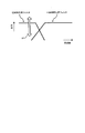
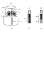
- FIG. 1 shows a schematic configuration of a speaker system according to the present embodiment. It is a block diagram which shows schematic structure of a control part. The figure for demonstrating sound quality correction
- amendment is shown.
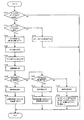
- the flowchart of the process by the speaker system which concerns on a present Example is shown.
- the schematic structure of the speaker system which concerns on the modification 4 is shown.
- the schematic structure of the speaker system which concerns on the modification 6 is shown.
- the example of a display of the upper limit of the volume which concerns on the modification 7 is shown.
- the schematic structure of the speaker system which concerns on the modification 8 is shown.
- a speaker system includes a first speaker that generates sound using an installation surface, a second speaker that generates sound without using the installation surface, and at least the first speaker. Based on the generated sound, suitability determination means for determining the suitability of the installation environment of the first speaker, and based on the suitability of the installation environment determined by the suitability determination means, the first speaker and the second speaker Correction means for performing sound quality correction so that the synthesized frequency characteristic of the sound generated by the speaker approaches the target frequency characteristic.
- the above speaker system generates sound using the first speaker that generates sound using the installation surface and the second speaker that generates sound without using the installation surface.
- the frequency band in charge differs between the first speaker and the second speaker.
- the suitability determining means determines suitability of the installation environment of the first speaker based on at least the sound generated by the first speaker.
- the aptitude determination means determines the output capability (reproduction capability) at the current installation location of the speaker system by analyzing at least the sound generated by the first speaker. In other words, the sound quality obtained at the location where the speaker system is currently installed is determined.
- the correction means determines whether the sound generated by the first speaker and the second speaker (the sound generated from the first speaker 2 itself, the operation of the first speaker 2 based on the determined suitability of the installation environment).
- the sound quality correction is performed so that the synthesized frequency characteristics of the sound generated at 90 and the sound generated from the second speaker 9 (hereinafter the same shall apply) approach the target frequency characteristics.
- the correction unit corrects the frequency characteristics of each of the first speaker and the second speaker in order to adjust the balance of the frequency characteristics of the entire speaker system.
- the correction means performs sound quality correction so that the frequency characteristics of the sum of sounds generated by the first speaker and the second speaker are smoothly connected. Thereby, it is possible to appropriately suppress variations in sound quality caused by differences in installation environments.
- the correction unit may be configured to adjust the frequency band component to be handled by the first speaker in an audio signal to be output by the speaker system according to the suitability of the installation environment.
- the sound quality correction is performed by decreasing the allocation ratio to the speakers and allocating them to the second speakers.
- the speaker system plays back regardless of the installation environment when the playback capability of the first speaker is reduced because the installation environment is not appropriate.
- the second speaker whose ability is substantially constant, the frequency band component originally handled by the first speaker is followed by the output of the second speaker. Thereby, even if the installation environment is not appropriate, the speaker system can appropriately generate the sound of the component in the frequency band that the first speaker is in charge of.
- the speaker system further includes means for limiting the upper limit of the volume of the speaker system in accordance with the degree to which the correction means allocates the frequency band component to the second speaker.
- the reason for controlling in this way is that when the frequency band component assigned to the first speaker is allocated to the second speaker, the sound tends to be distorted when the volume is increased. Therefore, the loudspeaker system restricts the upper limit of the volume of the whole loudspeaker system as the degree of allocation of the frequency band component to the second loudspeaker increases. Thereby, it is possible to appropriately suppress the generation of a distorted sound.
- the speaker system further includes means for displaying an upper limit of the volume of the speaker system according to the degree to which the correction means allocates the frequency band component to the second speaker. Also according to this aspect, when the component of the frequency band is allocated to the second speaker, it is possible to appropriately recognize the situation and appropriately suppress the generation of a distorted sound.
- the correction unit further includes means for displaying a degree to which the frequency band component is allocated to the second speaker.
- the user can easily grasp that the component of the frequency band is allocated to the second speaker, and the degree to which the component of the frequency band is allocated to the second speaker. Easy and appropriate grasp.
- the speaker system further includes means for stopping generation of sound from the first speaker when the suitability of the installation environment determined by the suitability determining means has not reached a predetermined level. . Thereby, it can suppress that the sound generated from the 1st speaker exerts a bad influence on the sound generated from the whole speaker system.
- the first speaker when the suitability of the installation environment determined by the suitability determining means does not reach a predetermined level, the first speaker is in charge within the range of the reproduction capability of the second speaker.
- the sound of the component of the frequency band to be generated can be generated from the second speaker.
- the speaker system further includes means for displaying the suitability of the installation environment determined by the suitability determining means.
- the speaker system notifies the user of visual information according to the suitability of the installation environment. As a result, it is possible to appropriately assist the user in selecting a better installation environment in terms of sound quality.
- the speaker system further includes detection means for detecting a change in the installation environment of the speaker system, and the correction means detects the change in the installation environment when the detection means detects the change in the installation environment. Perform sound quality correction.
- the sound quality can be corrected according to the changed installation environment.
- the detection unit does not detect a change in the installation environment if the installation surface in the installation environment after the change does not satisfy a predetermined condition.
- a predetermined condition For example, when the installation surface does not have a predetermined hardness or more, the detection unit does not detect a change in the installation environment. This is because, when the installation surface does not have a certain degree of hardness, it is difficult to obtain a planar baffle effect, and therefore it cannot be corrected by the correcting means.
- a low-frequency playback speaker can be used as the first speaker, and a mid-high frequency playback speaker can be used as the second speaker.
- the second speaker is configured in a spherical or polyhedral shape, and can be arranged so that the sound emission angle can be changed when placed or installed on the first speaker. It is configured.
- FIG. 1 shows a schematic configuration of a speaker system 50 according to the present embodiment.
- FIG. 1A shows a perspective view of the speaker system 50 observed from the side.
- signal lines are indicated by broken lines.
- FIG.1 (b) has shown the figure which observed the speaker system 50 from the direction shown by arrow A 1 in Fig.1 (a).
- FIG.1 (c) is the figure which showed specifically the display part 6 observed from the direction shown by arrow A 2 in Fig.1 (a).
- the speaker system 50 includes a control unit 1, a first speaker 2, a battery 3, a vibration isolator 4, a microphone 5, a display unit 6, a switch 7, 2 speakers 9.
- the speaker system 50 is configured to be relatively small, and is configured to be movable (in other words, portable).
- the speaker system 50 is basically used while being placed on a surface 90 having a relatively large area such as a desk or a floor.
- the surface on which the speaker system 50 is placed is referred to as an “installation surface”.
- the speaker system 50 is wired or wirelessly connected to a device (such as a playback device) not shown, and a music source is supplied from the device to generate a sound corresponding to the music source.
- a circular hole having substantially the same diameter as that of the first speaker 2 is provided on the bottom surface of the housing of the speaker system 50, and the first speaker 2 is fitted downward into the hole.
- the speaker box 20 in which the first speaker 2 is accommodated is joined to the speaker box 10 in which the second speaker 9 is accommodated by columns 8 arranged at four corners as shown in FIG. In FIG. 1 (a), the support column 8 is represented by a broken line for convenience of explanation).
- the surface of the speaker box 20 on which the first speaker 2 is installed is configured to be open.
- the speaker box 10 houses the control unit 1 in addition to the second speaker 9, and is configured to be hermetically sealed.
- the first speaker 2 is driven based on the low-frequency component signal of the audio signal, and the second speaker 9 is driven based on the mid-high frequency component signal of the audio signal. That is, the first speaker 2 is responsible for low-frequency reproduction, and the second speaker 9 is responsible for medium-high frequency reproduction.
- the first speaker 2 is responsible for a component of less than 200 [Hz]
- the second speaker 9 is responsible for the component of 200 [Hz] or higher.
- a vibration isolator 4 made of felt or the like is provided on the bottom surface of the speaker system 50 (specifically, between the first speaker 2 and the installation surface 90).
- the anti-vibration material 4 has a function of preventing chatter (meaning continuous vibration) and jumping of the speaker box 20 due to the vibration of the first speaker 2.
- the cone ring portion of the first speaker 2 is made of a member having elasticity and excellent durability.
- the sound emitted from the front surface of the first speaker 2 is prevented from being released into the air by the vibration isolator 4 and the installation surface 90, so that there is no reverse phase interference with the sound emitted from the back surface, and is emitted from the back surface.
- the baffle effect is obtained by the installation surface 90 only for the sound waves to be applied. Further, since the first speaker 2 is driven by a relatively strong magnet, low-frequency sound waves obtained by the cone ring of the first speaker 2 operating with a low-frequency audio signal vibrating the installation surface 90 (arrows) In addition to the baffle effect described above, a new baffle effect can be obtained by the installation surface 90. That is, the installation surface 90 having a relatively large area functions more as a flat baffle, and the low-frequency sound is reproduced more strongly.
- the bass reproduction capability is determined by the size of the speaker box and the like. That is, a general speaker cannot properly reproduce deep bass without a certain volume of the speaker box.
- the first speaker 2 described above generates sound using the planar baffle effect using the installation surface 90, it can be said that the size of the first speaker 2 hardly affects the output sound characteristics. In other words, even if the speaker system 50 is made compact, it can be said that it has little influence on the bass reproduction capability. As a result, it is possible to provide a speaker with high reproduction performance even in a small size.
- the level of the low frequency reproduction sound by the first speaker 2 varies depending on the conditions of the installation surface 90. For example, the level of the low-frequency reproduced sound changes depending on the material, hardness, area, etc. of the installation surface 90.
- the reproduction characteristics are constant regardless of the installation environment, that is, the medium / high frequency reproduction ability is constant. Is obtained.
- the first speaker 2 can obtain a sufficient bass reproduction effect with the help of an appropriate installation surface (such as a large area and appropriate hardness), while being affected by the installation surface. It can be said that it also has instability.
- the second speaker 9 is not expected to reproduce main and bass sounds, but is characterized by being sealed and stable. As long as there is an appropriate installation surface, the first speaker 2 is responsible for low sounds. However, if there is no appropriate installation surface, if the sound is emitted from the first speaker 2 forcibly, the overall sound will be poor and may have an adverse effect. Therefore, in such a case, a part of the second speaker 9 is assigned, or the reproduction from the first speaker 2 itself is stopped and the whole is reproduced by the second speaker 9, so that stable reproduction is appropriately performed. It is intended to maintain ability.
- the control unit 1 is electrically connected to the first speaker 2, the second speaker 9, the microphone 5, the display unit 6, and the switch 7, and signals are input / output between them.
- the control unit 1 controls the entire speaker system 50 by executing various processes.
- FIG. 2 is a block diagram showing a schematic configuration of the control unit 1.
- the control unit 1 mainly includes a microcomputer 11, a DSP (Digital Signal Processor) 12, and an amplifier 13.
- the microcomputer 11 controls the DSP 12 and the display unit 6 based on the signal supplied from the switch 7 and the like.
- the DSP 12 is supplied with audio signals collected by the music source and the microphone 5, and performs various processes on these based on the control of the microcomputer 11. Further, the DSP 12 allocates the supplied audio signal to the first speaker 2 and the second speaker 9. Specifically, the DSP 12 filters the frequency characteristics and allocates the low frequency component of the audio signal to the first speaker 2 and allocates the mid and high frequency components of the audio signal to the second speaker 9.
- the amplifier 13 amplifies the audio signals allocated to the first speaker 2 and the second speaker 9 by the DSP 12 and supplies them to the first speaker 2 and the second speaker 9.
- the first speaker 2 and the second speaker 9 operate according to the signal amplified by the amplifier 13.
- control unit 1 is not limited to being provided inside the speaker system 50, and some or all of the components of the control unit 1 may be provided outside the speaker system 50. That is, you may comprise the 1st speaker 2 and the 2nd speaker 9, and the control part 1 separately.
- the control unit 1 can be incorporated in a playback device or a device that controls the playback device.
- the microphone 5 is provided on the upper surface of the speaker system 50, and is configured to collect sound generated from below.
- An audio signal corresponding to the sound collected by the microphone 5 is supplied to the DSP 12 in the control unit 1.
- the display unit 6 performs a predetermined display in accordance with the control of the microcomputer 11 in the control unit 1. As shown in FIG. 1C, the display unit 6 is composed of, for example, three types of LEDs of green, yellow, and red, and these three types of LEDs are controlled according to the control of the microcomputer 11 in the control unit 1. One of the LEDs is turned on.
- the switch 7 is provided on the bottom surface of the speaker system 50, and is configured as a spring type as an example.
- the switch 7 is off in a state where it protrudes from the bottom surface of the speaker system 50 (a state where it is not installed on the floor surface), and when it is installed on the floor surface, the switch 7 is pushed down from the protruding state to turn on from off.
- the switch 7 is turned on when the speaker system 50 is placed on the installation surface 90 and turned off when the speaker system 50 is not placed on the installation surface 90.
- the switch 7 supplies a signal corresponding to ON / OFF to the microcomputer 11 in the control unit 1.
- control unit 1 corresponds to an example of aptitude determination means and correction means in the present invention
- switch 7 corresponds to an example of detection means in the present invention.
- the speaker system 50 according to the present embodiment performs sound quality correction according to the suitability of the installation environment of the speaker system 50.
- the reason for this is that, as described above, the speaker system 50 uses the planar baffle effect obtained by the installation surface 90 to generate bass, but the bass reproduction capability varies depending on the installation environment. For example, the material of the installation surface 90 (wood, resin, cloth, carpet, etc.), the undulations of the installation surface 90, the area of the installation surface 90, and the position where the speaker system 50 is placed on the installation surface 90 (whether it is placed in the center) ), The sound quality of the speaker system 50 tends to vary.
- the speaker system 50 performs sound quality correction in order to suppress variations in sound quality caused by differences in installation environment.
- the speaker system 50 is configured to output both the first speaker 2 and the second speaker 9 together (hereinafter referred to as “total audio output”) so that the maximum bass reproduction capability can be exhibited in the current installation environment. Sound quality correction).
- the speaker system 50 performs sound quality correction so that the synthesized frequency characteristic of the sound generated by the first speaker 2 and the second speaker 9 approaches the target frequency characteristic.
- the “sound generated by the first speaker 2 and the second speaker 9” includes sound generated from the first speaker 2 itself, sound generated on the installation surface 90 by the operation of the first speaker 2, and first sound. 2 It is assumed that the sound generated from the speaker 9 is included.
- the speaker system 50 When the installation environment is changed, the speaker system 50 generates sound corresponding to the test signal from the first speaker 2 and the second speaker 9 and collects the sound corresponding to the test signal with the microphone 5. That is, the speaker system 50 performs processing such as determination of the installation environment each time the user reinstalls the speaker system 50. In this case, the speaker system 50 detects a change in the installation environment by the switch 7. That is, the speaker system 50 generates a sound corresponding to the test signal from the first speaker 2 and the second speaker 9 by using the change from the OFF to the ON of the switch 7 as a trigger, thereby performing processing such as determination of the installation environment. I do.
- the speaker system 50 analyzes the sound collected by the microphone 5 and causes the display unit 6 to display the analysis result. Specifically, the speaker system 50 determines the suitability of the installation environment by analyzing the sound quality of the sound collected by the microphone 5, and displays the contents according to the determined suitability of the install environment on the display unit 6. Let For example, the speaker system 50 obtains a frequency characteristic for the sound collected by the microphone 5 and compares the obtained frequency characteristic with a predetermined reference value (for example, stored as a table value), thereby changing the installation environment. judge. In one example, the speaker system 50 determines the installation environment based on three-stage evaluation criteria such as “good”, “intermediate”, and “bad”.
- the speaker system 50 determines that the installation environment is “good” when the analysis result of the sound quality collected by the microphone 5 is equal to or higher than the first reference value, and the analysis result of the sound quality is the first reference value.
- the value is less than the second reference value (second reference value ⁇ first reference value) or more, it is determined that the installation environment is “intermediate”, and the sound quality analysis result is less than the second reference value. Determines that the installation environment is "bad”.
- the speaker system 50 turns on the LED in the display unit 6 according to the evaluation of the installation environment. For example, when the installation environment is “good”, the speaker system 50 turns on a green LED, and when the installation environment is “middle”, turns on a yellow LED, and the installation environment is “bad”. The red LED is turned on.
- the speaker system 50 performs sound quality correction based on the determination result of the installation environment as described above.
- the speaker system 50 has a sound quality so that the synthesized frequency characteristic of the sound generated by the first speaker 2 and the second speaker 9 approaches a target frequency characteristic (in other words, a reference characteristic, for example, stored as a table value). Make corrections. That is, sound quality correction is performed so that the frequency characteristics of the sum of sounds generated by the first speaker 2 and the second speaker 9 are smoothly connected. In other words, the speaker system 50 performs balance adjustment of the frequency characteristics of the entire speaker system 50 including the first speaker 2 and the second speaker 9.
- a target frequency characteristic in other words, a reference characteristic, for example, stored as a table value
- FIG. 3 shows an example of a low-frequency reproduction filter and a mid-high frequency reproduction filter.
- the speaker system 50 adjusts the low-frequency reproduction filter and the mid-high frequency reproduction filter as indicated by the arrow B1, thereby reducing the low-frequency reproduction capability obtained by the first speaker 2 and the installation surface 80.
- Low-frequency correction is performed in accordance with both the characteristics of the second speaker 9. Specifically, the speaker system 50 obtains a frequency characteristic for the sound collected by the microphone 5 and compares the obtained frequency characteristic with a target frequency characteristic to thereby obtain the first speaker 2 and the second speaker 9.
- the sound quality correction is performed so that the synthesized frequency characteristic of the sound generated by the method is as close as possible to the target frequency characteristic. That is, the DSP 12 in the speaker system 50 functions as an equalizer, and performs processing for the purpose of correcting (averaging) the overall sound quality.
- the speaker system 50 determines the low frequency component that the first speaker 2 should be in charge of according to the determined appropriateness of the installation environment if the installation environment is appropriate or acceptable.
- the sound quality correction as described above is performed by decreasing the allocation ratio to the first speaker 2 and allocating it to the second speaker 9.
- the ability of the first speaker 2 to bear the low frequency component varies depending on the suitability of the installation environment, so the speaker system 50 has the capability of the first speaker 2 to bear the low frequency component. Accordingly, the low frequency component is allocated to the second speaker 9, and the allocated low frequency component sound is generated from the second speaker 9.
- the low-frequency component is caused to follow by the second speaker 9 that has a low-frequency reproduction capability that is not as high as that of the first speaker 2 but maintains a stable reproduction capability.
- the speaker system 50 corrects the frequency characteristics used for the first speaker 2 so as to lower the output level of the low-frequency component and raise the output level of the low-frequency component for the second speaker 9. .
- the speaker system 50 the lower the ability of the first speaker 2 to bear the low frequency component (in other words, the lower the level of suitability of the installation environment), the lower the frequency component of the first speaker 2 is.
- the allocation ratio is further reduced to increase the degree of allocation of the low frequency component to the second speaker 9. That is, the speaker system 50 increases the degree of allocating the low frequency component to the second speaker 9 in accordance with the degree to which the allocation of the low frequency component to the first speaker 2 is reduced.
- the degree of allocating the low frequency component to the second speaker 9 can be set in advance as a table value in association with the appropriate level of the installation environment.
- the speaker system 50 is suitable when the suitability of the installation environment does not reach a predetermined level (for example, when the installation environment is “bad”), in other words, when the first speaker 2 can hardly bear the low frequency component, Generation of sound from the first speaker 2 can be stopped. This is because if the sound is generated from the first speaker 2 in this case, the sound generated from the second speaker 9 may be adversely affected. In this case, the speaker system 50 can fully output the low-frequency component sound from the second speaker 9 so as not to exceed the bass reproduction capability of the second speaker 9.
- such an output mode of the second speaker 9 is referred to as “single speaker output mode”.
- the single speaker output mode is a “single speaker output mode”.
- the speaker system 50 starts from the first speaker 2 without allocating a low frequency component to the second speaker 9. All the low frequency components are output, and only the middle and high frequency components are output from the second speaker 9.
- the speaker system 50 displays the suitability once after the suitability of the installation environment (in other words, the default sound reproduction capability at the place of installation) is determined, and then the suitability of the install environment after performing sound quality correction. (Sound correction capability after correction at the same place) can be displayed again. In other words, these can be displayed in the order of the suitability of the installation environment before the sound quality correction and the suitability of the installation environment after the sound quality correction. Instead of this, the speaker system 50 may display only the suitability of the installation environment after the sound quality correction without displaying the suitability of the installation environment before the sound quality correction.
- the switch 7 is used not only to detect a change in the installation environment as described above, but also to check whether the speaker system 50 is installed on the installation surface 90.
- the installation environment is determined when the installation environment is changed. However, in addition to this, the installation environment may be determined when the power source is turned on again. .
- the sound generation from the first speaker 2 is stopped and the sound is generated only from the second speaker 9. Can do. This is because if the sound is output from the first speaker 2 when the speaker system 50 is away from the installation surface 90, the sound becomes extremely small even though the first speaker 2 continues to vibrate. .
- the switch 7 detects the change in the installation environment.
- the switch 7 can detect the appropriateness of the installation position. Specifically, in another example, when the installation surface 90 does not have a hardness higher than a predetermined level, the switch 7 is not pushed down (ON state). In this case, the determination of the installation environment and sound quality correction are not performed. This is because the planar baffle effect cannot be obtained unless the installation surface 90 has a certain degree of hardness, so that the effect of sound quality correction or the like is hardly obtained. From such a viewpoint, it is desirable to set the spring constant of the spring constituting the switch 7 according to the hardness of the installation surface 90 so that an appropriate planar baffle effect can be obtained. For example, the spring constants of the springs constituting the switch 7 can be determined so that the switch 7 is pushed down from the protruding state on the installation surface 90 having a hardness such that an appropriate flat baffle effect can be obtained.
- switch 7 it is not limited to using a spring switch as the switch 7.
- Some normal switches are turned on by contact with a finger or a stick, but any known switch can be used as long as it is turned on by the act of being placed on the floor. good.
- the speaker system 50 may be controlled not to perform sound quality correction or the like when the determined installation environment does not satisfy the suitability condition, for example, when the installation environment is determined to be “bad”. good. This is because in such a case, the limit of the sound quality correction is exceeded, and it is determined that there is no meaning in performing the correction. In other words, the correction is performed aiming at a more suitable sound emission, and even if the correction is performed, it is meaningless to perform the correction if the target effect cannot be obtained.
- FIG. 4 shows a flowchart of processing by the speaker system 50 according to the present embodiment. This process is executed by the control unit 1 (specifically, the microcomputer 11 or the DSP 12) in the speaker system 50.
- the control unit 1 specifically, the microcomputer 11 or the DSP 12
- step S101a the microcomputer 11 in the control unit 1 determines whether or not the switch 7 remains on or off. If the switch 7 remains on or off (step S101a; Yes), the process ends. In this case, the control unit 1 maintains the same state as the state before executing the flow. On the other hand, when the switch 7 is not in the on or off state (step S101a; No), that is, when the switch 7 is changed from the on or off state, the process proceeds to step S101b.
- step S101b the microcomputer 11 in the control unit 1 determines whether or not the switch 7 has changed from OFF to ON.
- the switch 7 changes from OFF to ON step S101b; Yes
- the process proceeds to step S102.
- the switch 7 has not changed from OFF to ON (step S101b; No)
- the control unit 1 stops at least sound emission from the first speaker 2 (step S114).
- the control unit 1 may stop sound emission from the second speaker 9 or may continue sound emission from the second speaker 9. Then, the process ends.
- step S102 the DSP 12 in the control unit 1 outputs a predetermined test signal to the first speaker 2 and the second speaker 9. Then, the process proceeds to step S103.
- step S103 the DSP 12 acquires a microphone signal corresponding to the sound collected by the microphone 5. Then, the process proceeds to step S104.
- step S104 the DSP 12 analyzes the sound quality from the microphone signal acquired in step S103. Specifically, the DSP 12 analyzes the frequency characteristics of the sound generated by the speaker system 50. Then, the process proceeds to step S105. In step S105, the DSP 12 determines the installation environment based on the sound quality analyzed in step S104. That is, the DSP 12 determines the suitability of the installation environment. Then, the process proceeds to step S106.
- step S106 the DSP 12 determines whether or not the determination result in step S105 is greater than or equal to the first reference value. If the determination result is greater than or equal to the first reference value (step S106; Yes), the process proceeds to step S107.
- the installation environment is “good” when the installation environment is expressed by three-level evaluation criteria such as “good”, “intermediate”, and “bad”. Therefore, the microcomputer 11 turns on the green LED on the display unit 6 (step S107). Then, the DSP 12 performs sound quality correction of the total sound output of the first speaker 2 and the second speaker 9 so as to meet a predetermined sound quality reference value (in other words, a sound quality value corresponding to the target frequency characteristic or reference characteristic). (Step S108).
- the DSP 12 performs sound quality correction so that the synthesized frequency characteristic of the sound generated by the first speaker 2 and the second speaker 9 matches the target frequency characteristic. Then, the process ends. Note that the DSP 12 may not perform such sound quality correction when correction is unnecessary.
- step S109 the DSP 12 determines whether or not the determination result in step S105 is greater than or equal to the second reference value (second reference value ⁇ first reference value). If the determination result is greater than or equal to the second reference value (step S109; Yes), the process proceeds to step S110.
- the installation environment is “intermediate” when the installation environment is expressed by three-level evaluation criteria such as “good”, “intermediate”, and “bad”. Therefore, the microcomputer 11 turns on the yellow LED on the display unit 6 (step S110).
- the DSP 12 corrects the sound quality of the total sound output of the first speaker 2 and the second speaker 9 so as to approach a predetermined sound quality reference value (in other words, a sound quality value corresponding to the target frequency characteristic or reference characteristic).
- a predetermined sound quality reference value in other words, a sound quality value corresponding to the target frequency characteristic or reference characteristic.
- the DSP 12 performs sound quality correction so that the synthesized frequency characteristics of sounds generated by the first speaker 2 and the second speaker 9 are as close as possible to the target frequency characteristics.
- the process ends.
- the sound quality correction is performed as described above, when the suitability of the installation environment is changed from “intermediate” to “good”, the lighting of the LED of the display unit 6 is changed from yellow to green.
- step S109 when the determination result is less than the second reference value (step S109; No), the process proceeds to step S112.
- the microcomputer 11 in the control unit 1 turns on the red LED in the display unit 6 (step S112).
- the DSP 12 in the control unit 1 turns off the audio output to the first speaker 2 and switches the output mode of the second speaker 9 to the single speaker output mode (step S113). Then, the process ends.
- the synthesized frequency characteristic of the sound generated by the first speaker 2 and the second speaker 9 can be appropriately brought close to the desired frequency characteristic. That is, the balance adjustment of the frequency characteristics of the entire speaker system 50 can be appropriately performed. Therefore, it is possible to appropriately suppress variations in sound quality caused by differences in installation environments.
- Modification 1 In the above-described embodiment, the type of speaker using the planar baffle effect is shown, but the use of such a speaker is not limited to a speaker that generates sound using the installation surface.
- a speaker of a type that generates a sound by vibrating the installation surface by hitting the installation surface or the like can be used instead of the speaker using the flat baffle effect.
- the actuator has a function of a diaphragm, and the installation surface vibrated by the actuator has a function of cone paper, thereby generating sound.
- a speaker system is implement
- Modification 2 In the above-described embodiment, an example in which a change in the installation environment is detected by the switch 7 (in other words, a floor switch) is shown, but the present invention is not limited to detecting a change in the installation environment using such a switch 7.
- a light detection sensor that detects contact with the installation surface can be used instead of the switch 7.
- the light detection sensor is provided on the bottom surface of the speaker system and emits light downward. In this example, the light detection sensor detects that the speaker system is placed by blocking light when the speaker system is placed on the installation surface.
- the light detection sensor detects light inserted into the speaker housing when the speaker housing is “lifted” for movement, for example, from a state where the speaker housing is lying down.
- the photodetection sensor detects that the speaker housing has changed from a face-down state to a lifted state by detecting the brightness of the light.
- a sensor that detects that the user has touched the speaker system can be used.
- a contact detection sensor is provided on a side surface or an upper surface of a speaker housing, and the sensor detects that the speaker system is touched by a person for movement.
- the sensor not only when the speaker system is moved by floating from the installation surface, but also when the speaker system is moved while sliding on the installation surface without floating from the installation surface (for example, from the end of the installation surface) In the case of fine adjustment to a position closer to the center), it can be detected appropriately. In this case, it is possible to determine that the installation is complete upon the release after the contact by the user, and generate a sound corresponding to the test signal.
- Modification 3 In the above-described embodiment, an example is shown in which sound corresponding to the test signal is generated from the first speaker 2 and the second speaker 9 to perform processing such as determination of the installation environment.
- a test signal is used.
- the actual sound signal audio source or the like
- the reproduced sound is collected by the microphone 5 to perform processing such as determination of the installation environment. That is, in the third modification, when reproducing music, it is possible to always perform processing such as determination and correction of the installation environment while reproducing music in real time. This merit is not to miss because it corrects it to be a better sound while playing it regardless of the sound quality, and to set and correct the position while playing the audio source itself. It is easy to understand the situation of the source itself and how it is emitted.
- processing such as determination of an installation environment is performed based on sound generated from both the first speaker 2 and the second speaker 9 is shown, but the processing is performed only from the first speaker 2. Processing such as determination of the installation environment may be performed based on the sound.
- FIG. 5 shows a schematic configuration of a speaker system 50a according to the fourth modification.
- FIG. 5 schematically shows the outer shape of the speaker system 50a for convenience of explanation.
- the microphone 5a is provided at the end of the upper surface of the speaker system 50a (in other words, the position closer to the side surface of the speaker system 50a). Further, the microphone 5a is arranged at an angle such that the sound collection portion 5aa faces the bottom surface.
- Modification 5 In the embodiment described above, an example in which the user is notified by displaying the suitability of the installation environment has been shown, but instead of displaying the suitability or in addition to displaying the suitability, the suitability of the install environment is notified by voice. It's also good. That is, in the modified example 5, instead of using the visual information or in addition to using the visual information, a sound can be emitted according to the suitability of the installation environment.
- a predetermined level a value set in advance and stored in a memory or the like
- sound is generated from the first speaker 2
- the suitability of the installation environment is When the level has not been reached, no sound can be generated from the first speaker 2.
- audio data or the like is output from the first speaker 2 when the suitability of the installation environment reaches a predetermined level.
- the user can more intuitively select a better installation environment in terms of sound quality.
- the speaker system 50 in which the first speaker 2 and the second speaker 9 are integrally formed is shown.
- the first speaker and the second speaker are not integrally formed.
- the speaker system can be configured by separating the first speaker and the second speaker.
- the first speaker and the second speaker can be configured separately. In this case, since the first speaker and the second speaker are installed apart from each other, the speaker system performs wired or wireless control signal transmission and includes components necessary for control signal transmission.
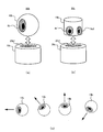
- FIG. 6 shows a schematic configuration of a speaker system according to Modification 6.
- FIG. 6A shows a speaker system 50b according to the sixth modification.
- a speaker box 20b in which a first speaker (not shown) is accommodated and a speaker box 10b in which a second speaker 9b is accommodated are configured separately.
- the speaker box 20b and the speaker box 10b are configured separately.
- the speaker system 50b is used in a state where the speaker box 10b is placed and fixed on the upper portion of the speaker box 20b using the recess 20b1 formed on the upper surface of the speaker box 20b.
- the speaker system 50b is used in a state where the speaker box 20b and the speaker box 10b are separated from each other, that is, in a state where the speaker box 20b and the speaker box 10b are installed in different places.
- FIG. 6B shows a speaker system 50c according to Modification 6.
- a speaker box 20c in which a first speaker (not shown) is accommodated and a speaker box 10c in which second speakers 9c1 and 9c2 are accommodated are configured in a separate manner.
- the speaker system 50c has the same basic configuration and basic functions as the speaker system 50b except that the speaker box 10c is provided with two second speakers 9c1 and 9c2.
- a display unit having the same function as the above-described display unit 6 (see FIG. 1) may be provided in the speaker systems 50b and 50c.
- the orientation of the second speaker box 9b is changed according to the relationship between the installation position and the user position with respect to the speaker box 20b of the first speaker serving as a base. (See FIG. 6C). That is, the sound emission angle of the second speaker (including both the elevation angle and the angle defined with respect to the horizontal plane parallel to the installation surface) can be changed.
- the present invention assumes that the speaker box 20b of the first speaker is installed on the floor, table surface or the like, but depending on the height of the installation position, for example, when it is placed close to the floor, the elevation angle to the upward direction Depending on how the second speaker is installed or fixed on the first speaker serving as a base, such as when it is installed on a high platform, the floor or table is the installation surface. Etc. can be used to amplify the low sound output from the first speaker and output the medium and high frequencies from the second speaker so that the user can comfortably listen.
- the second speaker is made spherical or polyhedral, etc., and the sound emission direction of the second speaker is defined appropriately and simply by the relationship between the user position and the installation position, A speaker device with excellent design can be provided.
- the sound emission direction of the speaker box 10c can be adjusted on the horizontal plane.
- the first speaker and the second speaker are configured separately as described above, different amplifiers are used for the first speaker and the second speaker, and the microcomputer and the DSP are the first speaker. And the second speaker. On the other hand, it is desirable to provide two microphones for the first speaker and the second speaker.
- the upper limit of the volume of the speaker system is limited according to the degree to which the low frequency component is allocated to the second speaker. This is because when the low frequency component is assigned to the second speaker, the sound tends to be distorted (in other words, the sound is broken) when the volume is increased. That is, when a low frequency component is assigned to the second speaker, it can be said that it is not desirable to increase the volume of the speaker system indefinitely from the viewpoint of sound distortion. Specifically, the higher the degree of allocating the low frequency component to the second speaker, the lower the upper limit of the volume at which sound distortion occurs. One reason for this is that the second speaker is primarily responsible for the mid-high range and is stable in a sealed type but is not suitable for low-frequency reproduction.
- the upper limit of the volume of the entire speaker system is limited as the degree of allocation of the low frequency component to the second speaker increases.
- a relationship between the degree to which the low-frequency component is allocated to the second speaker and the upper limit of the volume at which sound distortion occurs is obtained in advance by experiment or simulation, and the volume of the speaker system is determined according to the relationship.
- the upper limit can be limited.
- the modified example 7 instead of limiting the upper limit of the volume of the speaker system as described above, or in addition to limiting the upper limit of the volume of the speaker system, according to the degree to which the low frequency component is allocated to the second speaker.
- the upper limit of the volume of the entire speaker system can be displayed.
- it is possible to display in a visible form that the upper limit of the volume to be raised is lower as the degree of low frequency component allocation to the second speaker is larger.
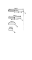
- FIG. 7 shows a display example of the upper limit of the volume.
- FIG. 7 illustrates four volume bars 101 to 104 indicating the volume variable range.
- the volume bars 101 to 104 are displayed on the side surface of the speaker system as described above.
- the volume bars 101 to 104 are defined by the upper limit V_MAX1 to V_MAX4 of the volume to be raised, respectively.
- the upper limits V_MAX1 to V_MAX4 of the volume have a relationship of “V_MAX1> V_MAX2> V_MAX3> V_MAX4”.
- the volume bar 101 is used when the low-frequency component is not allocated to the second speaker, that is, when both the first speaker and the second speaker can fully function, and there is no limit on the output volume.
- V_MAX1 corresponds to the maximum volume (default value) of the speaker system, that is, the upper limit V_MAX1 of the volume corresponds to the upper limit of the unrestricted volume.
- only the volume bars 101 and 102 indicate the currently set volume (indicated by hatching).
- the volume bar in which the upper limit of the volume is set lower is displayed as the degree of allocation of the low frequency component to the second speaker is larger.
- the volume bar 102 is displayed when the degree of low frequency component allocation is about “20%”
- the volume bar 103 is displayed when the level of low frequency component allocation is about “50%”.
- the degree of allocation of the low frequency component is “100%”
- the volume bar 104 is displayed.
- the improvement of the synthesized frequency characteristic in the speaker system Basically, there is a trade-off relationship between the improvement of the synthesized frequency characteristic in the speaker system and the upper limit of the volume raised in the speaker system. That is, when priority is given to improving the composite frequency characteristic, the volume must be sacrificed to some extent, and when priority is given to the volume, improvement of the composite frequency characteristic must be sacrificed to some extent.
- the above-described sound quality correction basically gives priority to the improvement of the composite frequency characteristic and sacrifices the sound volume to some extent. Instead of this, it is also possible to give priority to the volume that can be raised at the expense of some improvement in the synthesized frequency characteristics in the speaker system.
- the sound quality correction that imposes a limit on the degree to which the low frequency component is allocated to the second speaker so that the upper limit of the volume is secured above the predetermined value. It can be performed.
- the display as shown in FIG. 7 represents how much the sound volume is sacrificed by giving priority to the improvement of the synthesized frequency characteristic in the speaker system. Therefore, the user can grasp the degree of sacrificing the sound volume resulting from the priority of improving the composite frequency characteristic from the display. If the improvement of the synthesized frequency characteristic in the speaker system is sacrificed by giving priority to the volume to be raised, the improvement of the synthesized frequency characteristic due to the priority of the volume is used instead of the display as shown in FIG. The degree of sacrificing can be displayed.
- Such a display interface may be applied under conditions not limited to the configuration of the present application.
- the “total volume” or adjustable volume is presented, for example by the number of bars, display area, number of cell memory, etc.
- the currently set volume value is visible. That is, the entire adjustable range and the current set value within the range are grasped. It is intuitively understood what percentage is set for Max. The above is referred to as “condition 1”.
- condition 2 When the “total volume” changes under some conditions (reduced from condition 1), the bar length indicating the total volume, the display area, the number of cells, memory, etc. are reduced and displayed in a reduced form. The above is referred to as “condition 2”.
- the maximum volume of condition 2 (the upper limit volume that can be set) is lower than the non-maximum volume of condition 1, when the condition 1 changes to the condition 2 (since the user is affected by the situation at the time of the condition 1) How much volume is played at a certain point in condition 2 relative to the maximum volume that can be set in condition 2, or how much can be increased from the volume that is set at a certain point in time Etc. can be understood.
- the volume is used, but not limited to the volume setting, any parameter (setting value) may be used.
- any parameter setting value
- audio parameters, video parameters, etc. when the maximum value that can be set is changed due to the change from mode 1 (condition 1) to mode 2 (condition 2), depending on the length, area, and number of cells in the display (user interface) The difference between the two should be recognized in a comparable manner.
- Modification 8 In the modification 8, the degree to which the low frequency component is allocated to the second speaker is displayed. Specifically, in Modification 8, when a low frequency component is assigned to the second speaker, display is performed so that the output status of the first speaker and the second speaker can be visually recognized.
- FIG. 8 shows a schematic configuration of a speaker system according to Modification 8.
- FIG. 8A shows a speaker system 50d according to Modification 8.
- a level meter 152 is provided in a speaker box 20d in which a first speaker (not shown) is housed, and second speakers 9d1 and 9d2 (hereinafter referred to as “second speakers”).
- the level meter 151 is provided in the speaker box 10d in which “the second speaker 9d” is simply stored).
- the level meter 152 indicates the output status of the first speaker, and the level meter 151 indicates the output status of the second speaker 9d.
- the output state is indicated by hatching.
- the hatched portion corresponds to the lighting portion.
- the output state of the low-frequency component is represented by light color hatching, and the output state of the mid-high frequency component is illustrated by dark color hatching.
- the output status of the low-frequency component is displayed with green lighting, and the output status of the mid-high frequency component is displayed with red lighting.
- the level meter 151 displays only the lighting 151a indicating the output of the mid-high frequency component as shown in FIG. 8B, for example. In one example, the level meter 151 displays the output level only by lighting in red.
- the level meter 151 outputs the lighting 151b indicating the output of the mid-high frequency component and the output of the low frequency component as shown in FIG. 8C, for example.
- the lighting 151c to be displayed is displayed.
- the level meter 151 displays the output level by mixing red lighting with green lighting. In this case, the higher the degree of allocating the low frequency component to the second speaker 9d, the larger the lighting portion indicating the output of the low frequency component in the level meter 151.
- the output status of the first speaker and the second speaker can be easily grasped.
- the user can easily grasp that the low frequency component is allocated to the second speaker, and the low frequency component is allocated to the second speaker. It is possible to easily grasp the degree of being. Therefore, the user can recognize that the volume cannot be increased so much and the installation condition of the first speaker is not so good when the low frequency component is assigned to the second speaker.
- the first speaker is in charge of low-frequency reproduction
- the second speaker is in charge of medium-high frequency reproduction.
- the present invention is not limited to this. If the first speaker is a speaker that generates sound using the installation surface, and the second speaker is a speaker that generates sound without using the installation surface, the first speaker and the second speaker may have various frequency bands. Can be assigned.
- the present invention can be used for audio systems, home theater systems, and the like.
Landscapes
- Health & Medical Sciences (AREA)
- Otolaryngology (AREA)
- Physics & Mathematics (AREA)
- Engineering & Computer Science (AREA)
- Acoustics & Sound (AREA)
- Signal Processing (AREA)
- General Health & Medical Sciences (AREA)
- Circuit For Audible Band Transducer (AREA)
Abstract
スピーカシステムは、設置面を利用して音を発生させる第1スピーカと、設置面を利用せずに音を発生させる第2スピーカと、少なくとも第1スピーカによって発生された音に基づいて、第1スピーカの設置環境の適性を判定する適性判定手段と、適性判定手段によって判定された設置環境の適性に基づいて、第1スピーカ及び第2スピーカによって発生される音の合成周波数特性が目標の周波数特性に近付くように音質補正を行う補正手段と、を備える。これにより、設置環境の違いに起因する音質のばらつきを、適切に抑制することが可能となる。
Description
本発明は、設置面を利用して音を発生させるスピーカシステムに関する。
この種の技術が、例えば特許文献1及び2に記載されている。特許文献1には、スピーカ及びバスレフポートの開口面を底面に配置して音波を下方に放射することで、テーブルやデスクの表面に反射することで得られるバッフル効果を利用して、低音再生の向上を図った技術が提案されている。特許文献2には、バッフル板がキャビネットの底板から構成され、底板の開口部にスピーカ本体を下方に向けて取り付けると共に、底板の下側にスピーカ本体からの音を反射する反射板を設けたスピーカ装置が提案されている。
その他にも、本発明に関連する技術が特許文献3及び4に記載されている。特許文献3には、スピーカから出力させた測定用音声信号をマイクで収音し、その測定結果に基づいて音響装置の周波数特性を調節する技術が提案されている。特許文献4には、LEDランプにより表示された周波数特性を確認しながらバッフル板の開口部の面積を変えることで、周波数特性を調整する技術が提案されている。
しかしながら、上記した特許文献1乃至4に記載された技術では、設置面を利用して音を発生させるスピーカに関して、その設置環境の適性について判断を行って音質を適切に補正することができなかった。
本発明が解決しようとする課題としては、上記のものが一例として挙げられる。本発明は、設置面を利用して音を発生させる第1スピーカと設置面を利用せずに音を発生させる第2スピーカとを有するスピーカシステムに関して、設置環境の適性に応じて音質補正を適切に行うことを目的とする。
請求項1に記載の発明は、スピーカシステムであって、設置面を利用して音を発生させる第1スピーカと、前記設置面を利用せずに音を発生させる第2スピーカと、少なくとも前記第1スピーカによって発生された音に基づいて、前記第1スピーカの設置環境の適性を判定する適性判定手段と、前記適性判定手段によって判定された前記設置環境の適性に基づいて、前記第1スピーカ及び前記第2スピーカによって発生される音の合成周波数特性が目標の周波数特性に近付くように音質補正を行う補正手段と、を備えることを特徴とする。
本発明の1つの観点では、スピーカシステムは、設置面を利用して音を発生させる第1スピーカと、前記設置面を利用せずに音を発生させる第2スピーカと、少なくとも前記第1スピーカによって発生された音に基づいて、前記第1スピーカの設置環境の適性を判定する適性判定手段と、前記適性判定手段によって判定された前記設置環境の適性に基づいて、前記第1スピーカ及び前記第2スピーカによって発生される音の合成周波数特性が目標の周波数特性に近付くように音質補正を行う補正手段と、を備える。
上記のスピーカシステムは、設置面を利用して音を発生させる第1スピーカ、及び設置面を利用せずに音を発生させる第2スピーカを用いて、音を発生させる。例えば、第1スピーカと第2スピーカとでは、担当する周波数帯域が異なる。適性判定手段は、少なくとも第1スピーカによって発生された音に基づいて、第1スピーカの設置環境の適性を判定する。具体的には、適性判定手段は、少なくとも第1スピーカによって発生された音を分析することで、スピーカシステムの現在の設置場所における出力能力(再生能力)を判定する。言い換えると、スピーカシステムが現在設置されている場所で得られる音質についての判定を行う。
そして、補正手段は、判定された設置環境の適性に基づいて、第1スピーカ及び第2スピーカによって発生される音(第1スピーカ2自体から発生される音、第1スピーカ2の動作により設置面90で発生される音、及び第2スピーカ9から発生される音を含むものとする。以下同様とする。)の合成周波数特性が目標の周波数特性に近付くように音質補正を行う。具体的には、補正手段は、スピーカシステム全体の周波数特性のバランス調整を行うべく、第1スピーカ及び第2スピーカのそれぞれについて周波数特性の補正を行う。言い換えると、補正手段は、第1スピーカ及び第2スピーカによって発生される音の総和の周波数特性が滑らかに繋がるように音質補正を行う。これにより、設置環境の違いに起因する音質のばらつきを、適切に抑制することが可能となる。
上記のスピーカシステムの一態様では、前記補正手段は、前記スピーカシステムが出力すべき音声信号において前記第1スピーカが担当すべき周波数帯域の成分について、前記設置環境の適性に応じて、前記第1スピーカへの割り振りの比率を下げて前記第2スピーカへ割り振ることで、前記音質補正を行う。
この態様では、設置環境によって第1スピーカの再生能力が変化するため、スピーカシステムは、設置環境が適正でないために第1スピーカの再生能力が低下している場合に、設置環境に依らずに再生能力が概ね一定である第2スピーカを用いることで、本来第1スピーカが担当する周波数帯域の成分を第2スピーカの出力によってフォローする。これにより、設置環境が適正でない場合であっても、スピーカシステムは、第1スピーカが担当する周波数帯域の成分の音を適切に発生させることが可能となる。
上記のスピーカシステムの他の一態様では、前記補正手段が前記第2スピーカに前記周波数帯域の成分を割り振った度合いに応じて、前記スピーカシステムの音量の上限を制限する手段を更に備える。
このように制御するのは、第1スピーカが担当する周波数帯域の成分を第2スピーカに割り振った場合、音量を上げると音が歪む傾向にあるからである。よって、スピーカシステムは、第2スピーカに当該周波数帯域の成分を割り振った度合いが大きいほど、スピーカシステム全体の音量の上限を低く制限する。これにより、歪んだ音が発生してしまうことを適切に抑制することが可能となる。
上記のスピーカシステムの他の一態様では、前記補正手段が前記第2スピーカに前記周波数帯域の成分を割り振った度合いに応じた前記スピーカシステムの音量の上限を表示する手段を更に備える。この態様によっても、第2スピーカに当該周波数帯域の成分を割り振った場合に、状況を適切に認識し、歪んだ音が発生してしまうことを適切に抑制することが可能となる。
上記のスピーカシステムの他の一態様では、前記補正手段が前記第2スピーカに前記周波数帯域の成分を割り振った度合いを表示する手段を更に備える。
この態様によれば、ユーザは、第2スピーカに当該周波数帯域の成分が割り振られていることを容易に把握することができると共に、第2スピーカに当該周波数帯域の成分が割り振られている度合いを容易、かつ適切に把握することができる。
上記のスピーカシステムの他の一態様では、前記適性判定手段によって判定された前記設置環境の適性が所定レベルに達していない場合に、前記第1スピーカからの音の発生を停止させる手段を更に備える。これにより、第1スピーカから発生された音がスピーカシステム全体から発生される音に悪影響を及ぼしてしまうことを抑制することができる。
上記のスピーカシステムにおいて好適には、前記適性判定手段によって判定された前記設置環境の適性が所定レベルに達していない場合に、前記第2スピーカの再生能力の範囲内で、前記第1スピーカが担当すべき周波数帯域の成分の音を前記第2スピーカから発生させることができる。
上記のスピーカシステムの他の一態様では、前記適性判定手段によって判定された前記設置環境の適性を表示する手段を更に備える。
この態様では、スピーカシステムは、設置環境の適性に応じた視認情報をユーザに報知する。これにより、ユーザによる音質的により良い設置環境の選定を、適切にアシストすることが可能となる。
上記のスピーカシステムの他の一態様では、前記スピーカシステムの設置環境の変更を検出する検出手段を更に備え、前記補正手段は、前記検出手段によって前記設置環境の変更が検出された際に、前記音質補正を行う。
この態様によれば、スピーカシステムの設置環境が変更されるごとに、変更後における設置環境に応じた音質補正を行うことができる。
好適には、前記検出手段は、前記設置環境が変更された場合であっても、変更後の前記設置環境における前記設置面が所定条件を満たさない場合には、前記設置環境の変更を検出しない。例えば、設置面が所定以上の硬さを有しない場合には、検出手段は、設置環境の変更を検出しない。こうするのは、設置面がある程度の硬さを有しない場合には平面バッフル効果を得にくいため、補正手段により補正しきれないからである。
好適な実施例では、前記第1スピーカとして低域再生用のスピーカを用いることができ、前記第2スピーカとして中高域再生用のスピーカを用いることができる。
また好適な実施例では、前記第2スピーカは、球状もしくは多面体形状に構成されていると共に、前記第1スピーカに載置もしくは設置する際に、放音角度を変更可能に配することが可能に構成されている。
以下、図面を参照して本発明の好適な実施例について説明する。
[装置構成]
図1を参照して、本実施例に係るスピーカシステム50の構成について説明する。図1は、本実施例に係るスピーカシステム50の概略構成を示す。図1(a)は、スピーカシステム50を側方から観察した透視図を示している。なお、図1(a)では、信号線を破線で表している。図1(b)は、図1(a)中の矢印A1で示す方向からスピーカシステム50を観察した図を示している。図1(c)は、図1(a)中の矢印A2で示す方向から観察した、表示部6を具体的に示した図である。
図1を参照して、本実施例に係るスピーカシステム50の構成について説明する。図1は、本実施例に係るスピーカシステム50の概略構成を示す。図1(a)は、スピーカシステム50を側方から観察した透視図を示している。なお、図1(a)では、信号線を破線で表している。図1(b)は、図1(a)中の矢印A1で示す方向からスピーカシステム50を観察した図を示している。図1(c)は、図1(a)中の矢印A2で示す方向から観察した、表示部6を具体的に示した図である。
図1(a)に示すように、スピーカシステム50は、制御部1と、第1スピーカ2と、バッテリ3と、防振材4と、マイク5と、表示部6と、スイッチ7と、第2スピーカ9と、を有する。
スピーカシステム50は、比較的小型に構成されており、移動可能(言い換えると持ち運び可能)に構成されている。スピーカシステム50は、基本的には、机や床などの比較的広い面積を有する面90上に載置された状態で使用される。本明細書では、スピーカシステム50が載置された面を「設置面」と呼ぶこととする。また、スピーカシステム50は、図示しない装置(再生装置など)と有線接続若しくは無線接続されており、当該装置からミュージックソースが供給されて、当該ミュージックソースに対応する音を発生させる。
スピーカシステム50の筐体の底面には第1スピーカ2と概ね同じ径の円形の穴が設けられており、第1スピーカ2は当該穴に嵌め込まれて下向きに配置されている。第1スピーカ2が収納されたスピーカボックス20は、図1(b)に示すように4隅に配置された支柱8によって、第2スピーカ9が収納されたスピーカボックス10と接合されている(なお、図1(a)では、説明の便宜上、支柱8を破線で表している)。この場合、スピーカボックス20は、第1スピーカ2が設置された面がオープンに構成されている。一方、スピーカボックス10は、第2スピーカ9の他に制御部1が収納されており、密閉に構成されている。
第1スピーカ2は、音声信号のうち低域成分の信号に基づいて駆動され、第2スピーカ9は、音声信号のうち中高域成分の信号に基づいて駆動される。つまり、第1スピーカ2は低域再生を受け持ち、第2スピーカ9は中高域再生を受け持つ。例えば、音声信号において200[Hz]未満の成分を第1スピーカ2が受け持ち、200[Hz]以上の成分を第2スピーカ9が受け持つ。
スピーカシステム50の底面(具体的には第1スピーカ2と設置面90との間)には、フェルトなどで構成された防振材4が設けられている。防振材4は、第1スピーカ2の振動に起因する、スピーカボックス20のビビリ(継続的に発生する振動を意味する)や飛び跳ねを防止する機能を有する。また、第1スピーカ2のコーンリング部分は弾力性があり耐久性に優れた部材が用いられている。
第1スピーカ2の前面から出された音は、防振材4と設置面90により空中への放音が阻止されることにより、背面から出される音への逆位相干渉がなくなり、背面から放出される音波のみが、設置面90によりバッフル効果が得られる。また、第1スピーカ2は比較的強力な磁石で駆動されるため、低域音声信号で動作する第1スピーカ2のコーンリングが設置面90を振動させることにより得られる低域の音波も(矢印A3参照)、設置面90により前述のバッフル効果に加えて新たなバッフル効果が得られる。つまり、比較的面積の広い設置面90がより平面バッフルとして機能し、低域の音もより強く再生される。
ここで、第1スピーカ2のように、利用する設置面方向に向けて配置されておらず、平面バッフルを利用しないような一般的なスピーカでは、スピーカボックスのサイズなどで低音再生能力が決まる。つまり、一般的なスピーカでは、ある程度のスピーカボックスの容積がないと、総合的に重低音の再生を適切に行うことができない。しかしながら、上記した第1スピーカ2は、設置面90を用いて平面バッフル効果を利用して音を発生させるため、第1スピーカ2のサイズは出力される音特性にほとんど影響を与えないと言える。言い換えると、スピーカシステム50を小型に構成したとしても、そのことが低音再生能力に与える影響はほとんどないと言える。このことにより、小型でも再生性能の高いスピーカを提供することができる。但し、第1スピーカ2による低域再生音のレベルは、設置面90の条件で異なる。例えば、低域再生音のレベルは、設置面90の材質や硬さや面積などで変化する。
なお、第2スピーカ9は、一般的な密閉型タイプのスピーカであるため、設置環境に依らずに、再生特性(最大出力レベルや周波数特性)は一定している、つまり一定の中高域再生能力が得られる。
第1スピーカ2は適切な設置面(面積が広く適度な硬度がある等)があればその助けを得て十分な低音再生効果を得ることが出来る一方、設置面に影響される、強いていえば不安定さも備えると言える。他方、第2スピーカ9はメインで低音再生することを期待されないが、密閉型で安定しているという特徴がある。適切な設置面さえあれば、低音は第1スピーカ2に担わせるが、適切な設置面が無い場合、無理に第1スピーカ2から放音すると全体としての音が悪く、逆効果となる場合があるので、そのような場合には一部を第2スピーカ9に担わせたり、第1スピーカ2自体からの再生を停止して、全てを第2スピーカ9に再生させることにより、適宜安定した再生能力を維持せんとするものである。
制御部1は、第1スピーカ2、第2スピーカ9、マイク5、表示部6、及びスイッチ7と電気的に接続されており、これらの間で信号の入出力が行われる。制御部1は、種々の処理を実行することで、スピーカシステム50全体の制御を行う。
図2は、制御部1の概略構成を示すブロック図である。制御部1は、主に、マイコン11と、DSP(Digital Signal Processor)12と、アンプ13とを備える。マイコン11は、スイッチ7から供給された信号などに基づいてDSP12及び表示部6に対して制御を行う。DSP12は、ミュージックソースやマイク5で集音された音声信号が供給され、マイコン11の制御などに基づいて、これらに対して種々の処理を行う。また、DSP12は、供給された音声信号を第1スピーカ2と第2スピーカ9とに割り振る。具体的には、DSP12は、周波数特性をフィルタリングして、音声信号の低域成分を第1スピーカ2に割り振ると共に、音声信号の中高域成分を第2スピーカ9に割り振る。アンプ13は、DSP12によって第1スピーカ2及び第2スピーカ9に割り振られた音声信号をそれぞれ増幅して、第1スピーカ2及び第2スピーカ9に供給する。そして、第1スピーカ2及び第2スピーカ9は、それぞれ、アンプ13によって増幅された信号に応じて動作する。
なお、制御部1をスピーカシステム50の内部に設けることに限定はされず、制御部1の構成要素の一部又は全部をスピーカシステム50の外部に設けても良い。つまり、第1スピーカ2及び第2スピーカ9と、制御部1とを、別体に構成しても良い。例えば、再生装置や再生装置を制御する装置などに、制御部1を組み込むことができる。
図1に戻って説明を行う。マイク5は、スピーカシステム50の上面に設けられており、下方から発生された音を集音可能に構成されている。マイク5が集音した音に対応する音声信号は、制御部1内のDSP12に供給される。表示部6は、制御部1内のマイコン11の制御に応じて、所定の表示を行う。図1(c)に示すように、表示部6は、例えば緑色、黄色、赤色の3種類のLEDから構成されており、制御部1内のマイコン11の制御に応じて、これら3種類のLEDのうちの1つのLEDを点灯させる。
スイッチ7は、スピーカシステム50の底面に設けられており、一例としてはバネ式に構成されている。スイッチ7は、スピーカシステム50の底面から突出した状態(床面に設置されていない状態)ではオフとなっており、床面への設置に際し、当該突出した状態から押し下げられることでオフからオンとなる。基本的には、スイッチ7は、スピーカシステム50が設置面90に載置された状態ではオンとなり、スピーカシステム50が設置面90に載置されていない状態ではオフとなる。スイッチ7は、オン/オフに対応する信号を制御部1内のマイコン11に供給する。
なお、詳細は後述するが、制御部1は本発明における適性判定手段及び補正手段の一例に相当し、スイッチ7は本発明における検出手段の一例に相当する。
[スピーカシステムの動作]
次に、本実施例に係るスピーカシステム50の具体的な動作について説明する。本実施例に係るスピーカシステム50は、当該スピーカシステム50の設置環境の適性に応じて音質補正を行う。こうするのは、上記したように、スピーカシステム50は設置面90により得られる平面バッフル効果を利用して低音を発生させているが、その低音再生能力は設置環境によって変化するからである。例えば、設置面90の材質(木、樹脂、布、絨毯など)や、設置面90の起伏や、設置面90の面積や、設置面90においてスピーカシステム50を載置する位置(中央に置くか、端に置くかなど)によって、スピーカシステム50の音質がばらつく傾向にある。
次に、本実施例に係るスピーカシステム50の具体的な動作について説明する。本実施例に係るスピーカシステム50は、当該スピーカシステム50の設置環境の適性に応じて音質補正を行う。こうするのは、上記したように、スピーカシステム50は設置面90により得られる平面バッフル効果を利用して低音を発生させているが、その低音再生能力は設置環境によって変化するからである。例えば、設置面90の材質(木、樹脂、布、絨毯など)や、設置面90の起伏や、設置面90の面積や、設置面90においてスピーカシステム50を載置する位置(中央に置くか、端に置くかなど)によって、スピーカシステム50の音質がばらつく傾向にある。
このようなことから、本実施例に係るスピーカシステム50は、設置環境の違いに起因する音質のばらつきを抑制すべく音質補正を行う。この場合、スピーカシステム50は、現在の設置環境において最大の低音再生能力が発揮されるように、第1スピーカ2及び第2スピーカ9の両方を合わせた音声出力(以下、「総合音声出力」とも呼ぶ。)の音質補正を行う。具体的には、スピーカシステム50は、第1スピーカ2及び第2スピーカ9によって発生される音の合成周波数特性が目標の周波数特性に近付くように音質補正を行う。なお、「第1スピーカ2及び第2スピーカ9によって発生される音」には、第1スピーカ2自体から発生される音、第1スピーカ2の動作により設置面90で発生される音、及び第2スピーカ9から発生される音を含むものとする。
スピーカシステム50の動作をより具体的に説明する。スピーカシステム50は、設置環境が変更された際に、第1スピーカ2及び第2スピーカ9からテスト信号に対応する音を発生させて、当該テスト信号に対応する音をマイク5で集音させる。つまり、スピーカシステム50は、ユーザがスピーカシステム50を設置し直すごとに、設置環境の判定等の処理を行う。この場合、スピーカシステム50は、スイッチ7によって設置環境の変更を検出する。即ち、スピーカシステム50は、スイッチ7のオフからオンへの変化をトリガーにして、第1スピーカ2及び第2スピーカ9からテスト信号に対応する音を発生させることで、設置環境の判定等の処理を行う。
次に、スピーカシステム50は、マイク5で集音された音を分析し、分析結果を表示部6に表示させる。具体的には、スピーカシステム50は、マイク5で集音された音の音質を分析することで設置環境の適性を判定し、判定された設置環境の適性に応じた内容を表示部6に表示させる。例えば、スピーカシステム50は、マイク5で集音された音について周波数特性を求め、求められた周波数特性を所定の基準値(例えばテーブル値として記憶されている)と比較することで、設置環境を判定する。1つの例では、スピーカシステム50は、設置環境を「良好」、「中間」、「悪い」といった3段階の評価基準にて判定する。この場合、スピーカシステム50は、マイク5で集音された音質の分析結果が第1基準値以上である場合には設置環境が「良好」であると判定し、音質の分析結果が第1基準値未満で第2基準値(第2基準値<第1基準値)以上である場合には設置環境が「中間」であると判定し、音質の分析結果が第2基準値未満である場合には設置環境が「悪い」と判定する。
そして、スピーカシステム50は、設置環境についての評価に応じて、表示部6におけるLEDを点灯させる。例えば、スピーカシステム50は、設置環境が「良好」である場合には緑色のLEDを点灯させ、設置環境が「中間」である場合には黄色のLEDを点灯させ、設置環境が「悪い」場合には赤色のLEDを点灯させる。
次に、スピーカシステム50は、上記のような設置環境の判定結果に基づいて音質補正を行う。スピーカシステム50は、第1スピーカ2及び第2スピーカ9によって発生される音の合成周波数特性が目標の周波数特性(言い換えるとリファレンス特性であり、例えばテーブル値として記憶されている)に近付くように音質補正を行う。つまり、第1スピーカ2及び第2スピーカ9によって発生される音の総和の周波数特性が滑らかに繋がるように音質補正を行う。言い換えると、スピーカシステム50は、第1スピーカ2及び第2スピーカ9を含むスピーカシステム50全体の周波数特性のバランス調整を行う。
図3を参照して、音質補正について具体的に説明する。図3は、横軸に周波数を示し、縦軸に出力(出力レベル)を示している。また、図3には、低域再生用フィルタ及び中高域再生用フィルタの一例を示している。本実施例では、スピーカシステム50は、矢印B1で示すように低域再生用フィルタ及び中高域再生用フィルタをそれぞれ調整することで、第1スピーカ2と設置面80とで得られる低音再生能力及び第2スピーカ9の特性の両方に合わせて低域補正を行う。具体的には、スピーカシステム50は、マイク5で集音された音について周波数特性を求め、求められた周波数特性と目標の周波数特性とを比較することで、第1スピーカ2及び第2スピーカ9によって発生される音の合成周波数特性が目標の周波数特性に可能な限り近付くように音質補正を行う。つまり、スピーカシステム50内のDSP12がイコライザーとして機能して、全体的な音質の補正(平均化)を目的とした処理を行う。
より詳しくは、スピーカシステム50は、出力すべき音声信号において、設置環境が適正或いは許容範囲であれば、第1スピーカ2が担当すべき低域成分について、判定された設置環境の適性に応じて、第1スピーカ2への割り振りの比率を低下させて第2スピーカ9へ割り振ることで、上記したような音質補正を行う。つまり、設置環境の適性により第1スピーカ2が低域成分を担うことができる能力(低音再生能力)が変化するため、スピーカシステム50は、第1スピーカ2が低域成分を担うことができる能力に応じて、低域成分を第2スピーカ9に割り振って、割り振った低域成分の音を第2スピーカ9から発生させる。言い換えると、低域成分を、低域再生能力が第1スピーカ2ほど高くはないが密閉型で安定した再生能力を維持している第2スピーカ9によってフォローさせる。例えば、スピーカシステム50は、第1スピーカ2については低域成分の出力レベルを下げて、第2スピーカ9については低域成分の出力レベルを上げるように、それぞれに用いられる周波数特性の補正を行う。
この場合、スピーカシステム50は、第1スピーカ2が低域成分を担うことができる能力が低くなるほど(言い換えると設置環境の適性のレベルが低下するほど)、第1スピーカ2への低域成分の割り振りの比率をより低下させて、第2スピーカ9に低域成分を割り振る度合いを大きくする。つまり、スピーカシステム50は、第1スピーカ2への低域成分の割り振りを低下させた度合いに応じて、第2スピーカ9に低域成分を割り振る度合いを大きくする。例えば、低域成分を第2スピーカ9に割り振る度合いは、設置環境の適性のレベルなどに対応付けて、予めテーブル値として設定しておくことができる。
なお、スピーカシステム50は、設置環境の適性が所定レベルに達していない場合(例えば設置環境が「悪い」場合)、言い換えると第1スピーカ2が低域成分をほとんど担うことができないような場合、第1スピーカ2からの音の発生を停止させることができる。こうするのは、当該場合に第1スピーカ2から音を発生させると、第2スピーカ9から発生される音にも悪影響を及ぼしてしまう可能性があるからである。また、当該場合には、スピーカシステム50は、第2スピーカ9の低音再生能力を超えない程度に、第2スピーカ9から低域成分の音をフル出力させることができる。以下では、このような第2スピーカ9の出力モードを「スピーカ1個出力モード」と呼ぶ。スピーカ1個出力モードは、言い換えると「単一スピーカ出力モード」である。
一方で、スピーカシステム50は、設置環境の適性のレベルが高い場合(例えば設置環境が「良好」である場合)には、低域成分を第2スピーカ9に割り振ることなく、第1スピーカ2から低域成分を全て出力させ、第2スピーカ9からは中高域成分のみを出力させる。
なお、スピーカシステム50は、設置環境の適性(言い換えると、その設置場所でのデフォルト音声再生能力)が判定された後に当該適性を一旦表示し、この後に音質補正を行った後の設置環境の適性(同じ場所での補正後音声再生能力)を改めて表示することができる。つまり、音質補正前における設置環境の適性、音質補正後における設置環境の適性の順に、これらを表示することができる。この代わりに、スピーカシステム50は、音質補正前における設置環境の適性を表示せずに、音質補正後における設置環境の適性のみを表示することとしても良い。
なお、スイッチ7は、上記したように設置環境の変更を検出する以外にも、スピーカシステム50が設置面90に設置されているか否かを確認するためにも用いられる。また、上記では設置環境が変更された際に設置環境の判定等の処理を行うことを述べたが、これ以外にも、元電源の再投入時に設置環境の判定等の処理を行っても良い。
なお、スピーカシステム50が設置面90から離れている時は(つまりスイッチ7がオフである場合)、第1スピーカ2からの音の発生を停止し、第2スピーカ9のみから音を発生させることができる。これは、スピーカシステム50が設置面90から離れている時に第1スピーカ2から音を出力させると、第1スピーカ2が振動を続けるにも関わらず、音が極端に小さくなってしまうからである。
なお、上記ではスイッチ7が設置環境の変更を検出する例を示したが、他の例では、スイッチ7は、設置位置の適正を検出することができる。具体的には、他の例では、設置面90が所定以上の硬さを有しない場合には、スイッチ7が押し下げ状態(オンの状態)とならない。この場合、設置環境の判定や音質補正などは行われない。こうしているのは、設置面90がある程度の硬さを有しないと平面バッフル効果が得られないので、音質補正による効果などがほとんど得られないからである。こうした観点より、スイッチ7を構成するバネのバネ定数などは、適切な平面バッフル効果が得られるような設置面90の硬さに応じて設定することが望ましい。例えば、適切な平面バッフル効果が得られるような硬さを有する設置面90において、スイッチ7が突出状態から押し下げ状態となるように、スイッチ7を構成するバネのバネ定数などを定めることができる。
なお、スイッチ7としてバネスイッチを用いることに限定はされない。通常のスイッチにおいて、指や棒などにて接触することでオンにされるものがあるが、床面へ設置する行為によってオンとされるものであれば、公知のどのようなスイッチを用いても良い。
なお、スピーカシステム50は、判定された設置環境が適性条件を満たしていない場合には、例えば設置環境が「悪い」と判定された場合には、音質補正などを行わないように制御されても良い。このような場合には、音質補正の限界を超えており、補正をすることに意味が出ないと判断されるからである。つまり、より好適な放音を目指して補正するのであるから、たとえ補正を行ったとしても、目的効果が得られない場合には、補正を行う意味がないためである。
[スピーカシステムによる処理]
次に、図4を参照して、本実施例に係るスピーカシステム50による処理の一例を説明する。図4は、本実施例に係るスピーカシステム50による処理のフローチャートを示す。この処理は、スピーカシステム50内の制御部1(詳しくはマイコン11又はDSP12)によって実行される。
次に、図4を参照して、本実施例に係るスピーカシステム50による処理の一例を説明する。図4は、本実施例に係るスピーカシステム50による処理のフローチャートを示す。この処理は、スピーカシステム50内の制御部1(詳しくはマイコン11又はDSP12)によって実行される。
まず、ステップS101aでは、制御部1内のマイコン11が、スイッチ7がオン又はオフの状態のままであるか否かを判定する。スイッチ7がオン又はオフの状態のままである場合(ステップS101a;Yes)、処理は終了する。この場合には、制御部1は、当該フローを実行する前の状態と同じ状態を維持する。これに対して、スイッチ7がオン又はオフの状態のままでない場合(ステップS101a;No)、つまりスイッチ7がオン又はオフの状態から変化した場合、処理はステップS101bに進む。
ステップS101bでは、制御部1内のマイコン11は、スイッチ7がオフからオンに変化したか否かを判定する。スイッチ7がオフからオンに変化した場合(ステップS101b;Yes)、処理はステップS102に進む。この場合には、スピーカシステム50の設置環境が変更されたと言える。若しくは、スピーカシステム50の元電源が再投入されたと言える。これに対して、スイッチ7がオフからオンに変化していない場合(ステップS101b;No)、つまりスイッチ7がオンからオフに変化した場合、処理はステップS114に進む。この場合には、例えばスピーカシステム50が設置面90から持ち上げられた状態にあるため、制御部1は、少なくとも第1スピーカ2からの放音を停止する(ステップS114)。この場合、制御部1は、第2スピーカ9からの放音を停止しても良いし、第2スピーカ9からの放音を継続しても良い。そして、処理は終了する。
一方、ステップS102では、制御部1内のDSP12が、第1スピーカ2及び第2スピーカ9に対して所定のテスト信号を出力する。そして、処理はステップS103に進む。ステップS103では、DSP12が、マイク5が集音した音に対応するマイク信号を取得する。そして、処理はステップS104に進む。
ステップS104では、DSP12が、ステップS103で取得されたマイク信号より、音質を分析する。具体的には、DSP12は、スピーカシステム50によって発生された音の周波数特性を分析する。そして、処理はステップS105に進む。ステップS105では、DSP12が、ステップS104で分析された音質に基づいて、設置環境を判定する。つまり、DSP12は、設置環境の適性を判定する。そして、処理はステップS106に進む。
ステップS106では、DSP12が、ステップS105の判定結果が第1基準値以上であるか否かを判定する。判定結果が第1基準値以上である場合(ステップS106;Yes)、処理はステップS107に進む。この場合には、設置環境を「良好」、「中間」、「悪い」といった3段階の評価基準にて表現した場合、設置環境が「良好」であると言える。そのため、マイコン11は、表示部6における緑色のLEDを点灯させる(ステップS107)。そして、DSP12は、所定の音質基準値(言い換えると目標の周波数特性若しくはリファレンス特性に対応する音質の値)に合うように、第1スピーカ2及び第2スピーカ9の総合音声出力の音質補正を行う(ステップS108)。具体的には、DSP12は、第1スピーカ2及び第2スピーカ9によって発生される音の合成周波数特性が目標の周波数特性に一致するように音質補正を行う。そして、処理は終了する。なお、DSP12は、補正が不要な場合には、このような音質補正を行わないこととしても良い。
これに対して、判定結果が第1基準値未満である場合(ステップS106;No)、処理はステップS109に進む。ステップS109では、DSP12が、ステップS105の判定結果が第2基準値(第2基準値<第1基準値)以上であるか否かを判定する。判定結果が第2基準値以上である場合(ステップS109;Yes)、処理はステップS110に進む。この場合には、設置環境を「良好」、「中間」、「悪い」といった3段階の評価基準にて表現した場合、設置環境が「中間」であると言える。そのため、マイコン11は、表示部6における黄色のLEDを点灯させる(ステップS110)。そして、DSP12は、所定の音質基準値(言い換えると目標の周波数特性若しくはリファレンス特性に対応する音質の値)に近付くように、第1スピーカ2及び第2スピーカ9の総合音声出力の音質補正を行う(ステップS111)。具体的には、DSP12は、第1スピーカ2及び第2スピーカ9によって発生される音の合成周波数特性が目標の周波数特性に可能な限り近付くように音質補正を行う。そして、処理は終了する。なお、このように音質補正を行った場合において、設置環境の適性が「中間」から「良好」に変化した場合には、表示部6のLEDにおける点灯が黄色から緑色に変化される。
これに対して、判定結果が第2基準値未満である場合(ステップS109;No)、処理はステップS112に進む。この場合には、設置環境を「良好」、「中間」、「悪い」といった3段階の評価基準にて表現した場合、設置環境が「悪い」と言える。そのため、制御部1内のマイコン11は、表示部6における赤色のLEDを点灯させる(ステップS112)。そして、制御部1内のDSP12は、第1スピーカ2への音声出力をオフにすると共に、第2スピーカ9の出力モードをスピーカ1個出力モードに切り替える(ステップS113)。そして、処理は終了する。
以上説明した処理によれば、第1スピーカ2及び第2スピーカ9によって発生される音の合成周波数特性を所望の周波数特性に適切に近付けることができる。つまり、スピーカシステム50全体の周波数特性のバランス調整を適切に行うことができる。よって、設置環境の違いに起因する音質のばらつきを、適切に抑制することが可能となる。
[変形例]
次に、上記した実施例の変形例について説明する。なお、以下で示す変形例は、それぞれを種々に組み合わせて実施することができる。
次に、上記した実施例の変形例について説明する。なお、以下で示す変形例は、それぞれを種々に組み合わせて実施することができる。
(変形例1)
上記した実施例では、平面バッフル効果を利用するタイプのスピーカを示したが、設置面を利用して音を発生させるスピーカとして、このようなスピーカを用いることに限定はされない。変形例1では、平面バッフル効果を利用するタイプのスピーカの代わりに、設置面を叩く等することで設置面を振動させて音を発生させるタイプ(所謂アクチュエータタイプ)のスピーカを用いることができる。具体的には、変形例1に係るスピーカでは、アクチュエータが振動板の役目を有し、アクチュエータによって振動される設置面がコーン紙の役目を有することで、音を発生させる。なお、変形例1に係るスピーカをスピーカシステムに適用する場合、例えば、上記したスピーカシステム50の制御部1を同様に用いて、第1スピーカ2をアクチュエータに変更することでスピーカシステムが実現される。
上記した実施例では、平面バッフル効果を利用するタイプのスピーカを示したが、設置面を利用して音を発生させるスピーカとして、このようなスピーカを用いることに限定はされない。変形例1では、平面バッフル効果を利用するタイプのスピーカの代わりに、設置面を叩く等することで設置面を振動させて音を発生させるタイプ(所謂アクチュエータタイプ)のスピーカを用いることができる。具体的には、変形例1に係るスピーカでは、アクチュエータが振動板の役目を有し、アクチュエータによって振動される設置面がコーン紙の役目を有することで、音を発生させる。なお、変形例1に係るスピーカをスピーカシステムに適用する場合、例えば、上記したスピーカシステム50の制御部1を同様に用いて、第1スピーカ2をアクチュエータに変更することでスピーカシステムが実現される。
(変形例2)
上記した実施例では、スイッチ7(言い換えると床面スイッチ)によって設置環境の変更を検出する例を示したが、このようなスイッチ7を用いて設置環境の変更を検出することに限定はされない。変形例2では、スイッチ7の代わりに、設置面への接触を検出する光検出センサを用いることができる。1つの例では、光検出センサは、スピーカシステムの底面に設けられ、下方に向けて光を発する。この例では、光検出センサは、スピーカシステムが設置面に載置されると光が遮断されることで、スピーカシステムが載置されたことを検出する。
上記した実施例では、スイッチ7(言い換えると床面スイッチ)によって設置環境の変更を検出する例を示したが、このようなスイッチ7を用いて設置環境の変更を検出することに限定はされない。変形例2では、スイッチ7の代わりに、設置面への接触を検出する光検出センサを用いることができる。1つの例では、光検出センサは、スピーカシステムの底面に設けられ、下方に向けて光を発する。この例では、光検出センサは、スピーカシステムが設置面に載置されると光が遮断されることで、スピーカシステムが載置されたことを検出する。
他の例では、光検出センサは、例えばスピーカ筐体が茶碗を伏せたような状態から、移動のために“持ち上げた”際にスピーカ筐体の内部に差し込む光を検出する。言い換えると、当該光検出センサは、光の明るさを検出することにより、スピーカ筐体が伏せられた状態から持ち上げられた状態に変化したことを検出する。
更に、変形例2では、上記のようなセンサの他に、ユーザがスピーカシステムに接触したことを検出するセンサを用いることができる。例えば、スピーカ筐体の側面若しくは上面に接触検出センサを設け、当該センサは、スピーカシステムが移動のために人によって触れられたことを検出する。当該センサを用いた場合には、設置面から浮かせてスピーカシステムを移動させる場合に限らず、設置面から浮かさずに設置面上を滑らせながらスピーカシステムを移動させる場合(例えば設置面の端から中央寄りの位置に微調整するような場合)も適切に検出することができる。この場合には、ユーザによる接触後のリリースを契機に設置完了と判定して、テスト信号に対応する音を発生させることができる。
(変形例3)
上記した実施例では、第1スピーカ2及び第2スピーカ9からテスト信号に対応する音を発生させて設置環境の判定等の処理を行う例を示したが、このようなテスト信号を用いることに限定はされない。変形例3では、テスト信号を用いる代わりに、実際の音声信号(オーディオソース等)を用いて、その再生音をマイク5で集音することで設置環境の判定等の処理を行うことができる。つまり、変形例3では、音楽再生時において、リアルタイムで、音楽を再生させながら設置環境の判定及び補正等の処理を常時行うことができる。このメリットは、音質によらず曲りなりにも再生させながら、それがより良い音になるよう補正するため聴き逃さないこと、また、再生するオーディオソース自体を再生しながら位置設定及び補正を行うため、ソース自体の状況、どのように放音されるかを理解しやすいことである。
上記した実施例では、第1スピーカ2及び第2スピーカ9からテスト信号に対応する音を発生させて設置環境の判定等の処理を行う例を示したが、このようなテスト信号を用いることに限定はされない。変形例3では、テスト信号を用いる代わりに、実際の音声信号(オーディオソース等)を用いて、その再生音をマイク5で集音することで設置環境の判定等の処理を行うことができる。つまり、変形例3では、音楽再生時において、リアルタイムで、音楽を再生させながら設置環境の判定及び補正等の処理を常時行うことができる。このメリットは、音質によらず曲りなりにも再生させながら、それがより良い音になるよう補正するため聴き逃さないこと、また、再生するオーディオソース自体を再生しながら位置設定及び補正を行うため、ソース自体の状況、どのように放音されるかを理解しやすいことである。
また、上記した実施例では、第1スピーカ2及び第2スピーカ9の両方から発生された音に基づいて設置環境の判定等の処理を行う例を示したが、第1スピーカ2のみから発生された音に基づいて設置環境の判定等の処理を行っても良い。
(変形例4)
上記した実施例では、マイク5がスピーカシステム50の上面の中央付近に設けられた例を示したが(図1(a)参照)、このような位置にマイク5を配置することに限定はされない。
上記した実施例では、マイク5がスピーカシステム50の上面の中央付近に設けられた例を示したが(図1(a)参照)、このような位置にマイク5を配置することに限定はされない。
図5は、変形例4に係るスピーカシステム50aの概略構成を示す。図5では、説明の便宜上、スピーカシステム50aの外形を概略的に示している。変形例4では、マイク5aがスピーカシステム50aの上面の端(言い換えるとスピーカシステム50aの側面寄りの位置)に設けられている。また、マイク5aは、その集音部分5aaが底面の方向に向くような角度で配置されている。このようにマイク5aを配置することで、第1スピーカ2により設置面90で発生された音を効果的に集音することができる。言い換えると、スピーカシステム50aにおける上方からの余計な音の集音を、適切に抑制することができる。
(変形例5)
上記した実施例では、設置環境の適性を表示することでユーザに報知する例を示したが、適性を表示する代わりに、若しくは適性を表示するに加えて、設置環境の適性を音声によって報知することとしても良い。つまり、変形例5では、視認情報を用いる代わりに、若しくは視認情報を用いるに加えて、設置環境の適性に応じて音声を放音することができる。1つの例では、設置環境の適性が所定レベル(事前に設定され、メモリなどに記憶された値)に達している場合には第1スピーカ2から音を発生させ、設置環境の適性が当該所定レベルに達していない場合には第1スピーカ2から音を発生させないことができる。この例では、設置環境の適性が所定レベルに達した時点で、第1スピーカ2からオーディオデータ等が出力されることとなる。このような変形例5によれば、ユーザは、より直感的に、音質的により良い設置環境の選定を行うことができる。
上記した実施例では、設置環境の適性を表示することでユーザに報知する例を示したが、適性を表示する代わりに、若しくは適性を表示するに加えて、設置環境の適性を音声によって報知することとしても良い。つまり、変形例5では、視認情報を用いる代わりに、若しくは視認情報を用いるに加えて、設置環境の適性に応じて音声を放音することができる。1つの例では、設置環境の適性が所定レベル(事前に設定され、メモリなどに記憶された値)に達している場合には第1スピーカ2から音を発生させ、設置環境の適性が当該所定レベルに達していない場合には第1スピーカ2から音を発生させないことができる。この例では、設置環境の適性が所定レベルに達した時点で、第1スピーカ2からオーディオデータ等が出力されることとなる。このような変形例5によれば、ユーザは、より直感的に、音質的により良い設置環境の選定を行うことができる。
(変形例6)
上記した実施例では、第1スピーカ2と第2スピーカ9とが一体に構成されたスピーカシステム50を示したが、第1スピーカと第2スピーカとを一体に構成することに限定はされない。変形例6では、第1スピーカと第2スピーカとを別体にしてスピーカシステムを構成することができる。例えば、第1スピーカと第2スピーカとをセパレート式に構成することができる。この場合には、第1スピーカと第2スピーカとが離れて設置されるので、スピーカシステムは、有線もしくは無線による制御信号伝送を行い、制御信号伝送に必要な構成要素を具備することとなる。
上記した実施例では、第1スピーカ2と第2スピーカ9とが一体に構成されたスピーカシステム50を示したが、第1スピーカと第2スピーカとを一体に構成することに限定はされない。変形例6では、第1スピーカと第2スピーカとを別体にしてスピーカシステムを構成することができる。例えば、第1スピーカと第2スピーカとをセパレート式に構成することができる。この場合には、第1スピーカと第2スピーカとが離れて設置されるので、スピーカシステムは、有線もしくは無線による制御信号伝送を行い、制御信号伝送に必要な構成要素を具備することとなる。
図6は、変形例6に係るスピーカシステムの概略構成を示す。図6(a)は、変形例6に係るスピーカシステム50bを示す。図6(a)に示すように、スピーカシステム50bは、第1スピーカ(不図示)が収納されたスピーカボックス20bと第2スピーカ9bが収納されたスピーカボックス10bとが別体に構成されている。具体的には、スピーカシステム50bは、スピーカボックス20bとスピーカボックス10bとがセパレート式に構成されている。1つの利用例では、スピーカボックス20bの上面に形成された凹部20b1を用いて、スピーカボックス10bをスピーカボックス20bの上部に載置して固定した状態でスピーカシステム50bが使用される。他の利用例では、スピーカボックス20bとスピーカボックス10bとを離した状態で、つまりスピーカボックス20bとスピーカボックス10bとを別々の場所に設置した状態で、スピーカシステム50bが使用される。
図6(b)は、変形例6に係るスピーカシステム50cを示す。スピーカシステム50cも、第1スピーカ(不図示)が収納されたスピーカボックス20cと第2スピーカ9c1、9c2が収納されたスピーカボックス10cとがセパレート式に構成されている。スピーカシステム50cは、スピーカボックス10cに2つの第2スピーカ9c1、9c2が設けられている点以外は、スピーカシステム50bと基本構成及び基本機能は同様である。なお、上記した表示部6(図1参照)と同様の機能を有する表示部を、スピーカシステム50b、50cに設けても良い。
図6(a)のように第2スピーカが球状である場合、台座となる第1スピーカのスピーカボックス20bに対し第2スピーカボックス9bの向きを、設置位置とユーザ位置の関係等に応じて変更することが出来る(図6(c)参照)。つまり、第2スピーカの放音角度(仰角と、設置面と平行な水平面に対して規定される角度との両方を含む)を変更することができる。本発明は、第1スピーカのスピーカボックス20bの床やテーブル面等への設置を想定しているが、その設置位置の高さに応じて、例えば床に近い高さに置く場合は仰角~上向になるよう調整し、高い所にある台に設置した場合には下向きにする等、第2スピーカを台座となる第1スピーカ上にどのように設置あるいは固定するかによって、設置面である床やテーブル等を利用して第1スピーカから出力される低音を増幅させつつ、第2スピーカから中高域をユーザが快適に聴取出来るように出力するという効果を発揮できる。なお、台座部に第1スピーカを備えない場合でも、第2スピーカを球状、あるいは多面体等にし、ユーザ位置及び設置位置の関係により簡易に、適正に第2スピーカの放音方向を規定しつつ、意匠性にも優れたスピーカ装置を提供することが出来る。
なお、図6(b)に示したようなスピーカシステム50cについても、スピーカボックス10cを水平面上において放音方向を調整することができる。
なお、上記のように第1スピーカと第2スピーカとをセパレート式に構成した場合には、アンプは、第1スピーカと第2スピーカとで別のものを用い、マイコン及びDSPは、第1スピーカと第2スピーカとで共用することができる。一方で、マイクは、第1スピーカ用と第2スピーカ用とで2つ設けることが望ましい。
(変形例7)
変形例7では、第2スピーカに低域成分を割り振った度合いに応じて、スピーカシステムの音量の上限を制限する。こうするのは、第2スピーカに低域成分を割り振った場合、音量を上げると音が歪む(言い換えると音が割れる)傾向にあるからである。つまり、第2スピーカに低域成分を割り振った場合、音の歪みの観点から、際限なくスピーカシステムの音量を上げられるようにすることは望ましくないと言えるからである。具体的には、第2スピーカに低域成分を割り振った度合いが大きいほど、音の歪みが発生する音量の上限が低くなる傾向にある。このような理由の1つとしては、第2スピーカは元々中高域を主に担うものであり、密閉型で安定しているが、低域再生には適さないといった理由が挙げられる。
変形例7では、第2スピーカに低域成分を割り振った度合いに応じて、スピーカシステムの音量の上限を制限する。こうするのは、第2スピーカに低域成分を割り振った場合、音量を上げると音が歪む(言い換えると音が割れる)傾向にあるからである。つまり、第2スピーカに低域成分を割り振った場合、音の歪みの観点から、際限なくスピーカシステムの音量を上げられるようにすることは望ましくないと言えるからである。具体的には、第2スピーカに低域成分を割り振った度合いが大きいほど、音の歪みが発生する音量の上限が低くなる傾向にある。このような理由の1つとしては、第2スピーカは元々中高域を主に担うものであり、密閉型で安定しているが、低域再生には適さないといった理由が挙げられる。
したがって、変形例7では、第2スピーカに低域成分を割り振った度合いが大きいほど、スピーカシステム全体の音量の上限を低く制限する。例えば、実験やシミュレーション等により、第2スピーカに低域成分を割り振った度合いと、音の歪みが発生する音量の上限との関係を予め求めておき、当該関係に応じて、スピーカシステムの音量の上限を制限することができる。
また、変形例7では、上記のようにスピーカシステムの音量の上限を制限する代わりに、若しくはスピーカシステムの音量の上限を制限するに加えて、第2スピーカに低域成分を割り振った度合いに応じて定まる、スピーカシステム全体の音量の上限を表示することができる。具体的には、変形例7では、第2スピーカに低域成分を割り振った度合いが大きいほど、上げられる音量の上限が低いことを視認可能な形で表示させることができる。
図7は、音量の上限の表示例を示している。図7では、音量可変域を示す4つの音量バー101~104を例示している。音量バー101~104は、上記したようなスピーカシステムの側面などに表示される。
音量バー101~104は、それぞれ、上げられる音量の上限V_MAX1~V_MAX4によって規定されている。音量の上限V_MAX1~V_MAX4は、「V_MAX1>V_MAX2>V_MAX3>V_MA4」といった関係にある。音量バー101は第2スピーカに低域成分が割り振られていない場合、つまり第1スピーカ及び第2スピーカが共にフルに機能できる状況であり、出力音量に制限がない場合に用いられ、音量の上限V_MAX1はスピーカシステムの最大音量(デフォルト値)に相当する、つまり音量の上限V_MAX1は制限されていない音量の上限に相当する。なお、図7では、音量バー101、102についてのみ、現在設定されている音量(ハッチングで示す)などを示している。
一方で、第2スピーカに低域成分を割り振った場合には、第2スピーカに低域成分を割り振った度合いが大きいほど、音量の上限が低く設定された音量バーが表示される。例えば、低域成分を割り振った度合いが「20%」程度である場合には音量バー102が表示され、低域成分を割り振った度合いが「50%」程度である場合には音量バー103が表示され、低域成分を割り振った度合いが「100%」である場合には音量バー104が表示される。
このような変形例7によれば、第2スピーカに低域成分を割り振った場合において、例えば第2スピーカに極端に低域信号が入力されたことなどに起因して、歪んだ音が発生してしまうことを適切に抑制することが可能となる。
なお、基本的には、スピーカシステムにおける合成周波数特性の改善と、スピーカシステムにおいて上げられる音量の上限とはトレードオフの関係にある。つまり、合成周波数特性の改善を優先する場合には音量をある程度犠牲にする必要があり、音量を優先する場合には合成周波数特性の改善をある程度犠牲にする必要があると言える。ここで、上記した音質補正は、基本的には、合成周波数特性の改善を優先し、音量をある程度犠牲にしたものであった。この代わりに、スピーカシステムにおける合成周波数特性の改善をある程度犠牲にし、上げられる音量を優先することとしても良い。例えば、音量の上限が所定値以上となるような範囲内で、言い換えると音量の上限が所定値以上に確保されるように、第2スピーカに低域成分を割り振る度合いに制限を課した音質補正を行うことができる。
上記のような観点より、図7に示したような表示は、スピーカシステムにおける合成周波数特性の改善を優先することで、音量をどれだけ犠牲にしているのかを表していると言える。よって、ユーザは、当該表示から、合成周波数特性の改善の優先に起因する、音量を犠牲にしている度合いを把握することができる。なお、上げられる音量を優先することでスピーカシステムにおける合成周波数特性の改善を犠牲にした場合には、図7に示したような表示の代わりに、音量の優先に起因する、合成周波数特性の改善を犠牲にしている度合いを表示することができる。
このような表示インタフェースは、本願構成に限らない条件で適用されても良い。デフォルトの再生条件(制限がない場合)には、“全体ボリューム”つまり調整可能なボリュームが、例えばバーの長さ、表示面積、セル・メモリ等の数等によって提示されており、その上で、現在設定されているボリューム値が視認される。つまり、全体の調整可能範囲と、その範囲内における現在の設定値が把握される。マックスに対して何割程度に設定されているかが直感的に理解される。以上を「条件1」とする。
何らかの条件で“全体ボリューム”が変化する(条件1より低減される)場合には、全体ボリュームを示すバーの長さ、表示面積、セル・メモリ等の数等が減少、縮小した形で表示される。以上を「条件2」とする。
条件2の最大ボリューム(設定可能な上限ボリューム)は条件1の最大ではないボリュームよりも下回るので、条件1から条件2に変化した場合、(ユーザは条件1の時の状況に影響されるので)条件2のある時点において再生されている音量が、条件2において設定可能なマックスボリュームに対しどれくらいなのか、あるいは、ある時点で設定されているボリュームに対し、あとどれ位アップすることが可能なのか等を理解することが可能となる。
上記ではボリュームにて説明したが、音量設定に限らず、パラメータ(設定値)であれば何でも良い。音声パラメータ、映像パラメータ等において、モード1(条件1)からモード2(条件2)への変化によって設定可能な最大値が変更される場合は、表示(ユーザインタフェース)において長さや面積、セル数によって両者の違いが比較可能に認識されるようにする。
(変形例8)
変形例8では、第2スピーカに低域成分を割り振った度合いを表示する。具体的には、変形例8では、第2スピーカに低域成分を割り振った場合に、第1スピーカ及び第2スピーカの出力状況を視認できるような表示を行う。
変形例8では、第2スピーカに低域成分を割り振った度合いを表示する。具体的には、変形例8では、第2スピーカに低域成分を割り振った場合に、第1スピーカ及び第2スピーカの出力状況を視認できるような表示を行う。
図8は、変形例8に係るスピーカシステムの概略構成を示す。図8(a)は、変形例8に係るスピーカシステム50dを示す。図8(a)に示すように、スピーカシステム50dは、第1スピーカ(図示せず)が収納されたスピーカボックス20dにレベルメータ152が設けられていると共に、第2スピーカ9d1、9d2(以下、単に「第2スピーカ9d」と表記する。)が収納されたスピーカボックス10dにレベルメータ151が設けられている。レベルメータ152は第1スピーカの出力状況を示しており、レベルメータ151は第2スピーカ9dの出力状況を示している。図8では、レベルメータ151、152において、ハッチング部分で出力状況(出力レベル)を表している。ハッチング部分は、点灯部分に相当する。また、薄い色のハッチングで低域成分の出力状況を表しており、濃い色のハッチングで中高域成分の出力状況を示している。例えば、低域成分の出力状況は緑色の点灯で表示され、中高域成分の出力状況は赤色の点灯で表示される。
第2スピーカ9dに低域成分を割り振っていない場合には、レベルメータ151は、例えば図8(b)に示すような、中高域成分の出力を示す点灯151aのみを表示する。1つの例では、レベルメータ151は、赤色の点灯のみによって出力レベルを表示する。一方で、第2スピーカ9dに低域成分を割り振った場合には、レベルメータ151は、例えば図8(c)に示すような、中高域成分の出力を示す点灯151bと低域成分の出力を示す点灯151cとを表示する。1つの例では、レベルメータ151は、赤色の点灯に緑色の点灯を混ぜて出力レベルを表示する。この場合、第2スピーカ9dに低域成分を割り振った度合いが大きいほど、レベルメータ151において低域成分の出力を示す点灯部分が拡大される。
このような変形例8によれば、第1スピーカ及び第2スピーカの出力状況を容易に把握することができる。具体的には、変形例8に係る表示によれば、ユーザは、第2スピーカに低域成分が割り振られていることを容易に把握することができると共に、第2スピーカに低域成分が割り振られている度合いを容易に把握することができる。よって、ユーザは、第2スピーカに低域成分が割り振られている際に、あまり音量を上げられないこと、及び第1スピーカの設置条件があまり良くないことを認識することができる。
(変形例9)
上記した実施例では、第1スピーカに低域再生を受け持たせ、第2スピーカに中高域再生を受け持たせていたが、これに限定はされない。第1スピーカが設置面を利用して音を発生させるスピーカであり、第2スピーカが設置面を利用せずに音を発生させるスピーカであれば、第1スピーカ及び第2スピーカに種々の周波数帯域を受け持たせることができる。
上記した実施例では、第1スピーカに低域再生を受け持たせ、第2スピーカに中高域再生を受け持たせていたが、これに限定はされない。第1スピーカが設置面を利用して音を発生させるスピーカであり、第2スピーカが設置面を利用せずに音を発生させるスピーカであれば、第1スピーカ及び第2スピーカに種々の周波数帯域を受け持たせることができる。
本発明は、オーディオシステムやホームシアターシステムなどに利用することができる。
1 制御部
2 第1スピーカ
4 防振材
5 マイク
6 表示部
7 スイッチ
9 第2スピーカ
11 マイコン
12 DSP
13 アンプ
50 スピーカシステム
90 設置面
2 第1スピーカ
4 防振材
5 マイク
6 表示部
7 スイッチ
9 第2スピーカ
11 マイコン
12 DSP
13 アンプ
50 スピーカシステム
90 設置面
Claims (12)
- 設置面を利用して音を発生させる第1スピーカと、
前記設置面を利用せずに音を発生させる第2スピーカと、
少なくとも前記第1スピーカによって発生された音に基づいて、前記第1スピーカの設置環境の適性を判定する適性判定手段と、
前記適性判定手段によって判定された前記設置環境の適性に基づいて、前記第1スピーカ及び前記第2スピーカによって発生される音の合成周波数特性が目標の周波数特性に近付くように音質補正を行う補正手段と、を備えることを特徴とするスピーカシステム。 - 前記補正手段は、前記スピーカシステムが出力すべき音声信号において前記第1スピーカが担当すべき周波数帯域の成分について、前記設置環境の適性に応じて、前記第1スピーカへの割り振りの比率を下げて前記第2スピーカへ割り振ることで、前記音質補正を行うことを特徴とする請求項1に記載のスピーカシステム。
- 前記補正手段が前記第2スピーカに前記周波数帯域の成分を割り振った度合いに応じて、前記スピーカシステムの音量の上限を制限する手段を更に備えることを特徴とする請求項2に記載のスピーカシステム。
- 前記補正手段が前記第2スピーカに前記周波数帯域の成分を割り振った度合いに応じた前記スピーカシステムの音量の上限を表示する手段を更に備えることを特徴とする請求項2又は3に記載のスピーカシステム。
- 前記補正手段が前記第2スピーカに前記周波数帯域の成分を割り振った度合いを表示する手段を更に備えることを特徴とする請求項2乃至4のいずれか一項に記載のスピーカシステム。
- 前記適性判定手段によって判定された前記設置環境の適性が所定レベルに達していない場合に、前記第1スピーカからの音の発生を停止させる手段を更に備えることを特徴とする請求項1乃至5のいずれか一項に記載のスピーカシステム。
- 前記適性判定手段によって判定された前記設置環境の適性が所定レベルに達していない場合に、前記第2スピーカの再生能力の範囲内で、前記第1スピーカが担当すべき周波数帯域の成分の音を前記第2スピーカから発生させる手段を更に備えることを特徴とする請求項1乃至6のいずれか一項に記載のスピーカシステム。
- 前記適性判定手段によって判定された前記設置環境の適性を表示する手段を更に備えることを特徴とする請求項1乃至7のいずれか一項に記載のスピーカシステム。
- 前記スピーカシステムの設置環境の変更を検出する検出手段を更に備え、
前記補正手段は、前記検出手段によって前記設置環境の変更が検出された際に、前記音質補正を行うことを特徴とする請求項1乃至8のいずれか一項に記載のスピーカシステム。 - 前記検出手段は、前記設置環境が変更された場合であっても、変更後の前記設置環境における前記設置面が所定条件を満たさない場合には、前記設置環境の変更を検出しないことを特徴とする請求項9に記載のスピーカシステム。
- 前記第1スピーカは、低域再生用のスピーカであり、
前記第2スピーカは、中高域再生用のスピーカであることを特徴とする請求項1乃至10のいずれか一項に記載のスピーカシステム。 - 前記第2スピーカは、球状もしくは多面体形状に構成されていると共に、前記第1スピーカに載置もしくは設置する際に、放音角度を変更可能に配することが可能に構成されていることを特徴とする請求項1乃至11のいずれか一項に記載のスピーカシステム。
Priority Applications (1)
| Application Number | Priority Date | Filing Date | Title |
|---|---|---|---|
| PCT/JP2010/063104 WO2012017519A1 (ja) | 2010-08-03 | 2010-08-03 | スピーカシステム |
Applications Claiming Priority (1)
| Application Number | Priority Date | Filing Date | Title |
|---|---|---|---|
| PCT/JP2010/063104 WO2012017519A1 (ja) | 2010-08-03 | 2010-08-03 | スピーカシステム |
Publications (1)
| Publication Number | Publication Date |
|---|---|
| WO2012017519A1 true WO2012017519A1 (ja) | 2012-02-09 |
Family
ID=45559051
Family Applications (1)
| Application Number | Title | Priority Date | Filing Date |
|---|---|---|---|
| PCT/JP2010/063104 Ceased WO2012017519A1 (ja) | 2010-08-03 | 2010-08-03 | スピーカシステム |
Country Status (1)
| Country | Link |
|---|---|
| WO (1) | WO2012017519A1 (ja) |
Cited By (1)
| Publication number | Priority date | Publication date | Assignee | Title |
|---|---|---|---|---|
| CN114171036A (zh) * | 2021-12-14 | 2022-03-11 | 广东佳的美智能科技有限公司 | 蓝牙音箱的音质提升方法、装置及蓝牙音箱系统 |
Citations (14)
| Publication number | Priority date | Publication date | Assignee | Title |
|---|---|---|---|---|
| JPH06105390A (ja) * | 1992-09-18 | 1994-04-15 | Sony Corp | 音響信号再生装置 |
| JPH09182198A (ja) * | 1995-12-25 | 1997-07-11 | Sharp Corp | 音場報知装置 |
| JPH1169482A (ja) * | 1997-08-26 | 1999-03-09 | Akiyufueezu Kk | 音場特性の補正方法 |
| JP2001147693A (ja) * | 1999-11-19 | 2001-05-29 | Takahiro Yamashita | 音再生装置における再生出力の補正方法 |
| JP2001292490A (ja) * | 2000-04-05 | 2001-10-19 | Toa Corp | 音響システムにおける周波数特性設定装置 |
| JP2001343975A (ja) * | 2000-03-27 | 2001-12-14 | Kawai Musical Instr Mfg Co Ltd | 電子楽器の音響装置 |
| JP2002112371A (ja) * | 2000-10-03 | 2002-04-12 | Nippon Columbia Co Ltd | 音響信号増幅装置 |
| JP2003076374A (ja) * | 2001-09-07 | 2003-03-14 | Alpine Electronics Inc | オーディオ装置及びオーディオ装置の調整方法 |
| JP2004214707A (ja) * | 2002-12-26 | 2004-07-29 | Pioneer Electronic Corp | 音響装置および音響特性の変更方法および音響補正用プログラム |
| JP2005197842A (ja) * | 2003-12-26 | 2005-07-21 | Toshiba Corp | 音声処理装置 |
| WO2007116802A1 (ja) * | 2006-04-05 | 2007-10-18 | Pioneer Corporation | 出力制御装置、出力制御方法、出力制御プログラムおよび記録媒体 |
| JP2007295634A (ja) * | 2007-08-10 | 2007-11-08 | Yamaha Corp | 音出力システム |
| JP2009017137A (ja) * | 2007-07-03 | 2009-01-22 | Yamaha Corp | スピーカアレイ装置 |
| JP2009188474A (ja) * | 2008-02-04 | 2009-08-20 | Canon Inc | 音声再生装置及びその制御方法 |
-
2010
- 2010-08-03 WO PCT/JP2010/063104 patent/WO2012017519A1/ja not_active Ceased
Patent Citations (14)
| Publication number | Priority date | Publication date | Assignee | Title |
|---|---|---|---|---|
| JPH06105390A (ja) * | 1992-09-18 | 1994-04-15 | Sony Corp | 音響信号再生装置 |
| JPH09182198A (ja) * | 1995-12-25 | 1997-07-11 | Sharp Corp | 音場報知装置 |
| JPH1169482A (ja) * | 1997-08-26 | 1999-03-09 | Akiyufueezu Kk | 音場特性の補正方法 |
| JP2001147693A (ja) * | 1999-11-19 | 2001-05-29 | Takahiro Yamashita | 音再生装置における再生出力の補正方法 |
| JP2001343975A (ja) * | 2000-03-27 | 2001-12-14 | Kawai Musical Instr Mfg Co Ltd | 電子楽器の音響装置 |
| JP2001292490A (ja) * | 2000-04-05 | 2001-10-19 | Toa Corp | 音響システムにおける周波数特性設定装置 |
| JP2002112371A (ja) * | 2000-10-03 | 2002-04-12 | Nippon Columbia Co Ltd | 音響信号増幅装置 |
| JP2003076374A (ja) * | 2001-09-07 | 2003-03-14 | Alpine Electronics Inc | オーディオ装置及びオーディオ装置の調整方法 |
| JP2004214707A (ja) * | 2002-12-26 | 2004-07-29 | Pioneer Electronic Corp | 音響装置および音響特性の変更方法および音響補正用プログラム |
| JP2005197842A (ja) * | 2003-12-26 | 2005-07-21 | Toshiba Corp | 音声処理装置 |
| WO2007116802A1 (ja) * | 2006-04-05 | 2007-10-18 | Pioneer Corporation | 出力制御装置、出力制御方法、出力制御プログラムおよび記録媒体 |
| JP2009017137A (ja) * | 2007-07-03 | 2009-01-22 | Yamaha Corp | スピーカアレイ装置 |
| JP2007295634A (ja) * | 2007-08-10 | 2007-11-08 | Yamaha Corp | 音出力システム |
| JP2009188474A (ja) * | 2008-02-04 | 2009-08-20 | Canon Inc | 音声再生装置及びその制御方法 |
Cited By (1)
| Publication number | Priority date | Publication date | Assignee | Title |
|---|---|---|---|---|
| CN114171036A (zh) * | 2021-12-14 | 2022-03-11 | 广东佳的美智能科技有限公司 | 蓝牙音箱的音质提升方法、装置及蓝牙音箱系统 |
Similar Documents
| Publication | Publication Date | Title |
|---|---|---|
| US12058508B2 (en) | System and methods for improved acousto-haptic speakers | |
| JP5417352B2 (ja) | 音場制御装置及び方法 | |
| CN102656902B (zh) | 全向扬声器 | |
| JP6237768B2 (ja) | 音声出力装置、音声出力方法および映像表示装置 | |
| KR101915158B1 (ko) | 배향 응답성 음향 구동기 동작 | |
| JP6251458B1 (ja) | 音響装置 | |
| JP5610903B2 (ja) | 電気音響変換器 | |
| US10491984B2 (en) | Speaker device | |
| Ballou | Electroacoustic devices: microphones and loudspeakers | |
| JP7124708B2 (ja) | スピーカ装置及び再生装置 | |
| US9088841B2 (en) | Signal processor and method for compensating loudspeaker aging phenomena | |
| KR20210015619A (ko) | 소음 제거 장치 및 방법 | |
| US20180249243A1 (en) | Speaker device | |
| US11818537B2 (en) | Acoustic reproduction device | |
| US20080310669A1 (en) | Wire suspension for speakers | |
| JP5626096B2 (ja) | 天井設置用スピーカーシステムおよびこれを用いる照明装置 | |
| WO2012017519A1 (ja) | スピーカシステム | |
| JP2020038329A (ja) | サウンドシステム | |
| WO2012097300A1 (en) | Rhomboid shaped acoustic speaker | |
| JP4228996B2 (ja) | 電子鍵盤楽器 | |
| JP2024000668A5 (ja) | ||
| WO2012017518A1 (ja) | スピーカシステム | |
| US20150146898A1 (en) | Sound field supporting device and sound field supporting system | |
| JP3164791U (ja) | スピーカーシステム | |
| WO2020070837A1 (ja) | 音響装置及び音響再生方法 |
Legal Events
| Date | Code | Title | Description |
|---|---|---|---|
| 121 | Ep: the epo has been informed by wipo that ep was designated in this application |
Ref document number: 10855609 Country of ref document: EP Kind code of ref document: A1 |
|
| NENP | Non-entry into the national phase |
Ref country code: DE |
|
| 122 | Ep: pct application non-entry in european phase |
Ref document number: 10855609 Country of ref document: EP Kind code of ref document: A1 |
|
| NENP | Non-entry into the national phase |
Ref country code: JP |