WO2012014982A1 - X線回折方法及びそれを用いた可搬型x線回折装置 - Google Patents
X線回折方法及びそれを用いた可搬型x線回折装置 Download PDFInfo
- Publication number
- WO2012014982A1 WO2012014982A1 PCT/JP2011/067278 JP2011067278W WO2012014982A1 WO 2012014982 A1 WO2012014982 A1 WO 2012014982A1 JP 2011067278 W JP2011067278 W JP 2011067278W WO 2012014982 A1 WO2012014982 A1 WO 2012014982A1
- Authority
- WO
- WIPO (PCT)
- Prior art keywords
- ray
- rays
- diffracted
- sample
- polycapillary
- Prior art date
- Legal status (The legal status is an assumption and is not a legal conclusion. Google has not performed a legal analysis and makes no representation as to the accuracy of the status listed.)
- Ceased
Links
Images
Classifications
-
- G—PHYSICS
- G01—MEASURING; TESTING
- G01N—INVESTIGATING OR ANALYSING MATERIALS BY DETERMINING THEIR CHEMICAL OR PHYSICAL PROPERTIES
- G01N23/00—Investigating or analysing materials by the use of wave or particle radiation, e.g. X-rays or neutrons, not covered by groups G01N3/00 – G01N17/00, G01N21/00 or G01N22/00
- G01N23/20—Investigating or analysing materials by the use of wave or particle radiation, e.g. X-rays or neutrons, not covered by groups G01N3/00 – G01N17/00, G01N21/00 or G01N22/00 by using diffraction of the radiation by the materials, e.g. for investigating crystal structure; by using scattering of the radiation by the materials, e.g. for investigating non-crystalline materials; by using reflection of the radiation by the materials
-
- G—PHYSICS
- G01—MEASURING; TESTING
- G01N—INVESTIGATING OR ANALYSING MATERIALS BY DETERMINING THEIR CHEMICAL OR PHYSICAL PROPERTIES
- G01N23/00—Investigating or analysing materials by the use of wave or particle radiation, e.g. X-rays or neutrons, not covered by groups G01N3/00 – G01N17/00, G01N21/00 or G01N22/00
- G01N23/20—Investigating or analysing materials by the use of wave or particle radiation, e.g. X-rays or neutrons, not covered by groups G01N3/00 – G01N17/00, G01N21/00 or G01N22/00 by using diffraction of the radiation by the materials, e.g. for investigating crystal structure; by using scattering of the radiation by the materials, e.g. for investigating non-crystalline materials; by using reflection of the radiation by the materials
- G01N23/207—Diffractometry using detectors, e.g. using a probe in a central position and one or more displaceable detectors in circumferential positions
-
- G—PHYSICS
- G01—MEASURING; TESTING
- G01N—INVESTIGATING OR ANALYSING MATERIALS BY DETERMINING THEIR CHEMICAL OR PHYSICAL PROPERTIES
- G01N23/00—Investigating or analysing materials by the use of wave or particle radiation, e.g. X-rays or neutrons, not covered by groups G01N3/00 – G01N17/00, G01N21/00 or G01N22/00
- G01N23/20—Investigating or analysing materials by the use of wave or particle radiation, e.g. X-rays or neutrons, not covered by groups G01N3/00 – G01N17/00, G01N21/00 or G01N22/00 by using diffraction of the radiation by the materials, e.g. for investigating crystal structure; by using scattering of the radiation by the materials, e.g. for investigating non-crystalline materials; by using reflection of the radiation by the materials
- G01N23/20008—Constructional details of analysers, e.g. characterised by X-ray source, detector or optical system; Accessories therefor; Preparing specimens therefor
-
- G—PHYSICS
- G01—MEASURING; TESTING
- G01N—INVESTIGATING OR ANALYSING MATERIALS BY DETERMINING THEIR CHEMICAL OR PHYSICAL PROPERTIES
- G01N2223/00—Investigating materials by wave or particle radiation
- G01N2223/05—Investigating materials by wave or particle radiation by diffraction, scatter or reflection
- G01N2223/056—Investigating materials by wave or particle radiation by diffraction, scatter or reflection diffraction
-
- G—PHYSICS
- G01—MEASURING; TESTING
- G01N—INVESTIGATING OR ANALYSING MATERIALS BY DETERMINING THEIR CHEMICAL OR PHYSICAL PROPERTIES
- G01N2223/00—Investigating materials by wave or particle radiation
- G01N2223/30—Accessories, mechanical or electrical features
- G01N2223/301—Accessories, mechanical or electrical features portable apparatus
-
- G—PHYSICS
- G01—MEASURING; TESTING
- G01N—INVESTIGATING OR ANALYSING MATERIALS BY DETERMINING THEIR CHEMICAL OR PHYSICAL PROPERTIES
- G01N2223/00—Investigating materials by wave or particle radiation
- G01N2223/30—Accessories, mechanical or electrical features
- G01N2223/33—Accessories, mechanical or electrical features scanning, i.e. relative motion for measurement of successive object-parts
Definitions
- the present invention relates to an X-ray diffraction method for analyzing a material by irradiating a sample with X-rays of continuous wavelength generated by an X-ray tube, and a portable X-ray diffraction apparatus using the same.
- the X-ray diffraction method has been established as a method for measuring the material of unknown crystal samples and measuring a part of a large sample or a sample mounted on various substrates. Along with this, there has been a growing demand for a measuring device that can be used outdoors even in analyzers that have been used in buildings. Recent advances in electronic technology have made power supplies and control circuits smaller, lighter, and consume less power. However, in the normal X-ray diffraction method, there is a problem that the measurement accuracy or sensitivity deteriorates when the sample position deviates from the predetermined position, and the sample position is set to the predetermined position using a mechanical angle measuring device called a goniometer. X-ray diffraction measurement as shown in FIG.
- Patent Document 1 discloses a portable X-ray diffractometer intended for measurement of specific partial X-ray diffraction.
- Non-Patent Document 2 describes an X-ray diffraction measurement method without an X-ray angle measuring device using an X-ray detector capable of energy analysis of X-ray photons.
- X-ray diffraction is measured by measuring the X-ray diffraction intensity with respect to the X-ray diffraction angle using an X-ray detector, and therefore, it is necessary to move the sample and the detector at each angle and move the angle and position. . Therefore, in order to hold the X-ray source and the detector and to ensure the accuracy of the angular movement, the mechanical angle measuring instrument inevitably requires weight, and it has been difficult to use it as a portable X-ray diffractometer.
- the energy analysis X-ray diffractometer that does not require angular movement has a large X-ray detector and is configured to increase the distance between sample detectors in order to ensure X-ray diffraction measurement accuracy. It has been difficult to construct a portable X-ray diffractometer by weight and size.
- the angle measuring instrument described in Non-Patent Document 1 is a mechanical type, and it has been difficult to reduce the size and weight. Moreover, in the apparatus described in Patent Document 1, it is necessary to use an apparatus having a complicated configuration using a jig for installing the apparatus on a sample and a plurality of two-dimensional detectors. Furthermore, in the X-ray diffraction measurement method without an X-ray angle measuring instrument described in Non-Patent Document 2, it is necessary to cool the X-ray detector to the liquid nitrogen temperature, and a large refrigerant container is required. In order to obtain measurement accuracy, the distance between the sample detectors is increased, and it is not necessarily used as a portable X-ray diffractometer.
- the present invention has been achieved in view of the problems in the prior art described above, and the object thereof is to realize a small and lightweight X-ray diffraction apparatus, which is sufficiently stable even under use conditions held by human power. It is an object to provide an X-ray diffraction method capable of acquiring accurate data and a portable X-ray diffraction apparatus using the same.
- the present invention has been achieved in view of the realization of a small and lightweight portable X-ray diffractometer that can be held by human power, and is particularly based on the knowledge of the inventors described below. That is, in the case of performing X-ray diffraction measurement, conventionally, measurement has been performed under such a condition that the positional relationship between the incident X-ray, the sample, and the diffraction X-ray is reliably maintained. For example, diffracted X-rays from a sample are measured using characteristic X-rays emitted from an X-ray tube (when the target is Cu, the wavelength of K ⁇ 1 is 0.154056 nm).
- This measurement condition is based on Bragg's law, and a mechanical angle setting machine called a goniometer is used so that the positional relationship between the X-ray tube, the sample, and the X-ray detector is accurately maintained.
- This mechanical goniometer is heavy and is not necessarily suitable as a device for measuring by holding it manually. The measurement is not affected by the displacement of the sample position because it is held by human power, and it is configured without using a goniometer.
- An X-ray diffraction method and an X-ray diffraction apparatus using the same have been desired.
- a portable X-ray diffractometer is composed of an X-ray irradiation means for irradiating a sample with parallel X-rays and a sample irradiated with X-rays by the X-ray irradiation means.
- Diffraction X-ray detection means for collecting and detecting diffracted X-rays of parallel components among the diffracted X-rays, and signal processing means for processing signals output from the diffracted X-ray detection means for detecting diffracted X-rays And configured.
- the present invention irradiates a sample with X-rays of parallel continuous wavelengths, and extracts parallel components from the diffracted X-rays diffracted by the sample irradiated with the X-rays.
- the portion of the sample that is irradiated with X-rays is imaged, an image of the portion of the sample that is irradiated with X-rays is displayed, and is continuously displayed using an X-ray tube.
- X-rays of wavelength are generated, the X-rays generated by the X-ray tube are collimated, and the X-rays of the sample on which the image is displayed are irradiated from an oblique direction.
- a parallel component is selected from the diffracted X-rays and collected, and the selected and collected diffracted X-rays are detected by the detection element, and the signal detected by the detection element is processed. .
- an X-ray diffractometer having a size and weight that can be transported and held by human power, and to perform X-ray diffraction measurement while observing a microscopic image of a specific portion of a large sample on a display display.
- an X-ray diffraction method and a portable X-ray measurement apparatus using the X-ray diffraction method capable of stably measuring an X-ray of a specific portion even when the surface is uneven or the sample is easily displaced are provided. be able to.
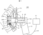
- FIG. 1 is a diagram showing an overall configuration of a portable X-ray diffraction apparatus 100 according to an embodiment of the present invention.
- An X-ray generation X-ray tube 1, an X-ray shutter 2, a sample irradiation X-ray optical element 3, an X-ray transmission window 22, and an X-ray detection unit 30 are disposed inside the casing 21 on the X-ray irradiation unit 20 side.
- An X-ray transmission window 32, a diffracted X-ray receiving optical element 4, and an X-ray detector 5 are housed inside the casing 31 on the side.
- sample observation unit 6, the X-ray generation high voltage power source 7, the detector signal processing unit 8, the high voltage power source and shutter opening / closing control unit 9, the data processing and display control unit 10, the power storage unit 11, the power cable 12, the handle 13, The shutter opening / closing switch 14 and the foldable data display unit 15 are mounted on the housing unit 50.
- the casing 21 on the X-ray irradiation unit 20 side and the casing 31 on the X-ray detection unit 30 side are spatially connected to each other and are respectively mounted on the casing unit 50. Further, the inside of the casing 21 on the X-ray irradiation unit 20 side and the casing 31 on the X-ray detection unit 30 side is evacuated to a vacuum by a vacuum evacuation unit (not shown). Furthermore, the X-ray irradiated to the sample 200 from the X-ray irradiation unit 20 side is externally attached to the surface of the casing 21 on the X-ray irradiation unit 20 side and the casing 31 on the X-ray detection unit 30 side on the sample 200 side. A ring-shaped X-ray shield sample contact portion 40 for preventing leakage of the X-ray is attached, and the contact portion 41 contacts the sample 200 to prevent the X-ray from leaking to the outside.
- the X-ray generated by the X-ray generation X-ray tube 1 is turned on / off by irradiating the sample by opening and closing the X-ray shutter 2 by the shutter opening / closing switch 14.
- X-rays generated in the X-ray generation X-ray tube 1 with the shutter 2 opened by the shutter opening / closing switch 14 are transmitted through the sample irradiation X-ray optical element 3 and irradiated onto the sample 200.
- the X-ray optical element 3 for sample irradiation has a role of collimating X-rays generated by the X-ray generation X-ray tube 1 and irradiating the sample 200.
- the X-ray optical element 3 for X-ray generation 1 A slit having an aperture of the same size as the line focus 16 was used.
- the sample irradiation X-ray optical element 3 may be a parallel tube type monocapillary or a polycapillary type element formed by bundling a plurality of parallel tube type monocapillaries.
- the diffracted X-ray receiving optical element 4 a polycapillary type element formed by bundling a plurality of parallel tube type monocapillaries was used.
- the X-ray reflected by the sample 200 incident on the polycapillary diffracted X-ray light receiving optical element 4 has a parallel component transmitted through the polycapillary diffracted X-ray light receiving optical element 4 and has an X-ray energy resolution. 5 and the diffracted X-rays from the sample are measured.
- the polycapillary diffracted X-ray light receiving optical element 4 is formed such that the emitted X-rays are collected on a detection surface (not shown) of the X-ray detector 5.
- An analog signal obtained by detecting X-rays with the X-ray detector 5 is digitized so that data can be processed by the detector signal processing unit 8, processed by the data processing and display control unit 10, and the result is folded data. It is displayed on the display unit 15. Moreover, the center of the optical axis of the X-ray of the X-ray diffraction measurement of the portable X-ray diffraction measuring apparatus 100 according to the present embodiment is indicated by alternate long and short dashed lines a and b in the figure.
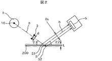
- the position of the sample 100 is ideally the S position with respect to the optical axis center a of the X-ray of X-ray diffraction measurement.
- the sample 200 In actual measurement with the portable X-ray diffraction measurement apparatus 100 held by hand, it is difficult to keep the sample 200 at the ideal position, and the amount varies as indicated by L as shown in FIG. It is assumed that they will shift.
- the position of the sample 200 that causes diffraction at this time is between S1 and S2 (variation width L).
- D 0 L ⁇ sin ( ⁇ 1 + ⁇ 2) / sin (( ⁇ 1 + ⁇ 2) / 2) (Equation 1)
- ⁇ 1 is an incident angle of the sample irradiating X-ray optical element 3 to the sample
- ⁇ 2 is an emission angle of X-rays diffracted by the sample. Both ⁇ 1 and ⁇ 2 are set in the range of 10 ° to 60 °.
- the light receiving surface of the X-ray detector 5 ′ has the following formula in order to stably measure the diffracted X-ray even if the sample position is shifted by L.
- D 1 the numerical value shown in (Equation 2).
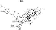
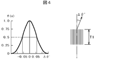
- X-rays incident on the polycapillary 4 at an angle of the total reflection critical angle are about once every 100 ⁇ m.
- the total reflection occurs 100 times in the parallel polycapillary 4 having a T1 length of 10 mm shown in FIG. If the reflectance of total reflection is 0.99 at this time, the X-rays incident from the incident end 401 side of the polycapillary 4 at 0.125 degrees are almost absorbed inside the polycapillary.
- the polycapillary 4 formed by collecting the monocapillaries having a glass tube inner wall diameter of 200 nm and a length of 10 mm in a bundle can select only a parallel X-ray beam having an angular divergence of about 0.12 degrees.
- the operation of the collimator using such a polycapillary 4 can be performed by an ordinary stacked type, and a miniaturized stacked type collimator can also be used.
- the X-ray emitted from the emission end 402 of the polycapillary 4 converges on the detection surface of the X-ray detector 5 on the side of the emission end 402 of the polycapillary 4, and the size of the detection surface is increased. since such can be made smaller than D 1, as compared with the configuration described in FIG. 2, now downsizing of X-ray detector 5.
- Opening diameter D 1 of the side of the entrance end 401 of the X-ray receiving optical element 4 is dependent on the expression (2), a practical dimension X-ray beam diameter (d) of 1 mm, displacement of the sample position (L) If ⁇ 2 mm, the aperture diameter (D 1 ) on the incident end 401 side of the light receiving optical system needs to be about 9 mm.
- a silicon drift type semiconductor detector (SDD) which is an energy dispersive detector, having a diameter of 10 mm has been commercialized and can be obtained. It is possible to directly use the SDD as the detector 5.
- a light receiving optical element that reduces the diameter of the X-ray detector 5 by using the characteristics of the polycapillary was used.
- the total reflection critical angle of the quartz surface is 0.125 degrees (2.2 mrad), so that the reflection angle is about 0.25 degrees in one total reflection. Is possible. If the diameter of the polycapillary is reduced smoothly from the light receiving portion (X-ray incident side) in a spheroidal shape, the diameter of the diffracted X-rays can be reduced by total reflection on the inner wall of the polycapillary.
- the diffracted X-rays incident on 401 can be condensed and emitted from the emission end 402. At this time, if the reflectance of total reflection is 0.99, the decrease in X-ray intensity is only about 20%.
- the X-ray detector 5 can be a detector having a diameter of 6 mm (area 25 mm 2 ) instead of a detector having a diameter of 10 mm (area 80 mm 2 ).
- large silicon drift semiconductor detectors are expensive and small detectors are superior in terms of energy resolution, so it is advantageous to use small optical elements.
- T2 50 mm on the side of the emitting end 402 having a cross-sectional shape of a spheroidal surface
- the opening diameter on the side of the emitting end 402 is set to about 2 mm, and an area of 7 mm 2 (mass diameter 3 mm) that is normally mass-produced. Inexpensive detectors can be used.
- the length is 50 mm and the aperture diameter 10 mm on the incident end 401 side is reduced to 5 mm on the outgoing end 402 side.
- a polycapillary having a spheroidal shape was obtained. Since this polycapillary only needs to collect incident X-rays and emit them to the X-ray detector 5 side, the shape does not need to be focused and can be a smooth two-dimensional curved surface. It is.
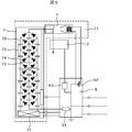
- the X-ray generation X-ray tube 1, the X-ray generation high voltage power source 7, the high voltage power source and the shutter opening / closing control 9 used in the embodiment of the present invention will be described with reference to FIG.
- the X-ray tube 1 for generating X-rays a small X-ray tube with ceramic insulation was used. A glass tube type can also be used. If the anode (target) is grounded in the overall circuit configuration, a high-voltage insulated filament transformer is required when a hot cathode is used. In this embodiment, the cathode grounding type is used. In this case, the heat (10 W) generated in the X-ray generating X-ray tube 1 is radiated from the X-ray measuring device main body by heat conduction through the high-voltage insulating material.
- a 12-stage full-wave rectification cockcroft-Wolton high-voltage boost rectifier circuit 70 was used for the high-voltage power supply 7 for X-ray generation.
- High-frequency power was supplied to the Cockcroft-Wolton high voltage boost rectifier circuit 70 by a piezo transformer 71.
- a single piezo transformer 71 was used to supply 4 kV-10 W.
- the operating frequency of the piezo transformer 71 is about 80 kHz. Power is supplied to the piezo transformer 71 at a high frequency of ⁇ 24 V from the high voltage power source and the shutter opening / closing control unit 9.
- the high voltage power supply / shutter opening / closing control unit 9 is negatively fed back from the applied voltage of the 80 kHz high frequency transmission circuit 91 and the X-ray generation X-ray tube 1 so that the voltage set by the data processing and display control unit 10 is set from the outside. Be controlled.
- the high-voltage power supply / shutter opening / closing control unit 9 includes a filament current control unit 92 for controlling the current of the X-ray generation X-ray tube 1 and a switch circuit 93 for the X-ray shutter.
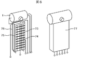
- the X-ray generation X-ray tube 1 and the X-ray generation high-voltage power supply 7 are integrally molded in a high-voltage power supply safety shield 77, and all the external terminals of the high-voltage power supply safety shield 77 are used at a voltage of 24V or less. The safety of adjustment and inspection work is planned.
- the piezo transformer 72 is used to reduce the size and weight, but it is also possible to use a high-frequency coil transformer that requires only a slight increase in weight.
- the high-voltage power supply 7 for generating X-rays was formed on a ceramic substrate 75 using a chip capacitor 73, a chip diode 74, and a chip resistor not shown in FIG. These chip parts were used for surface mounting and were made compact. Since one stage of the Cockcroft-Wolton high voltage step-up rectifier circuit 70 is set to 4 kV, a bridge circuit 72 is formed by connecting two 4 kV withstand voltage chip capacitors 73 and two 2 kV withstand voltage chip diodes 74 in series. did. Therefore, in the embodiment of the present invention, the maximum applied voltage is 48 kV and the rated operating voltage and current are 40 kV-0.25 mA. If a higher voltage is required, it can be handled by increasing the number of multiplication stages.
- the high voltage power supply 7 for X-ray generation has a voltage dividing chip register (not shown) for negative voltage feedback control mounted on the back surface of the ceramic substrate 75 and a piezoelectric (piezoelectric) transformer 78 mounted thereon. Since the piezo transformer 78 is a thin rectangular strip, the piezo transformer 78 is most suitable for small mounting. Moreover, compared with an electromagnetic high frequency transformer, when it employs in a small apparatus, it is excellent also from a viewpoint of electromagnetic noise. However, since it vibrates at high frequency (80 kHz) in principle, it was mounted on a substrate in a case 77 made of Teflon (registered trademark).
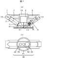
- FIG. 7 (a) X-rays generated at the X-ray focal point 16 of the X-ray generation X-ray tube 1 pass through the X-ray optical element 3 for sample irradiation, and are shown in FIG. 7 (b).
- the sample 200 is irradiated through the sample irradiation X-ray transmission window 22 provided on the sample surface side of the X-ray shield part 40.
- the contact portion 41 with the sample 200 is made of heavy metal such as tungsten (W), tantalum (Ta), lead (Pb), etc., and it can be prevented from leaking X-rays by being in close contact with the sample.
- a plastic piece containing heavy metal not shown in the figure is installed outside according to the shape of the sample to prevent X-ray leakage. Furthermore, after confirming whether the contact part 41 of the X-ray shielding part 40 is in contact with the sample from the data by the sample observation part 6 that performs optical measurement through the proximity switch and the sample observation opening 42 not shown in the figure. Therefore, the X-ray irradiation is controlled by turning the shutter opening / closing switch 14 on / off.
- a part of the X-rays irradiated to the sample 200 passes through the diffraction X-ray detection transmission window 32 as diffraction X-rays and enters the diffraction X-ray receiving optical element 4, and is guided to the X-ray detector 5 to be X-ray diffraction data. Is measured.
- a molybdenum (Mo) counter-cathode (target) is used for the X-ray tube 1 for X-ray generation, and the sample irradiation X-ray angle ( ⁇ 1) and the diffraction X-ray extraction angle ( ⁇ 2) are set to 20 degrees.
- the d value that can be measured was changed from 0.7 nm to 0.07 nm.
- the wavelength range of X-rays used at this time is 0.5 nm to 0.07 nm. Since X-rays with a wavelength of 0.3 nm or more such as X-rays with a wavelength of 0.5 nm (2.4 keV) are easily absorbed in the atmosphere, the casing 21 of the X-ray irradiation unit 20 side and the housing of the X-ray detection unit 30 are used. The inside of the cylinder 31 is evacuated by means not shown. In the case of this embodiment, a complete vacuum sealing structure is used, but it is not possible to exhaust completely with a pump only when it is used, not a complete vacuum sealing.
- the space between the casing 31 and the casing 50 of the X-ray detection unit 30 is held rotatably.
- the housing 50 can be manually rotated to display the measurement data on the folding data display unit 15.
- the direction in which a specific diffraction pattern appears can be specified, and it can be measured how the crystals that cause X-ray diffraction are oriented in the sample.
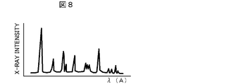
- FIG. 1 An example of a detection signal output from the X-ray detector 5 that has detected the diffracted X-ray is shown in FIG.
- an energy dispersive SDD is used as the X-ray detector 5. Since the SDD is a one-pixel sensor, X-rays diffracted from the sample 200 in the direction of the diffraction angle ⁇ 2 are incident on the large-diameter incident end 401 of the polycapillary 4 and are about the pixel size of the X-ray detector 5. It is effective to improve detection sensitivity by converging to.
- the detection signal processing unit 8 Upon receiving the detection signal as shown in FIG. 8, the detection signal processing unit 8 processes the signal and calculates the crystal lattice spacing of the sample 200.
- the crystal plane distance d can be obtained from the detection signal as shown in FIG.
- the internal stress of the sample 200 can be obtained from the relationship between the internal stress and the crystal interval using the obtained data of the crystal interval d.
- molybdenum (Mo) when used as the anode target of the X-ray tube 1, X-rays in the energy range of 3 to 15 KeV can be detected. Detection is possible in the range of 0.41 to 0.083 nm.
- silver (Ag) is used as the anode target of the X-ray tube 1
- X-rays in the energy range of 3 to 20 keV can be detected. It can be detected in the range of 41 to 0.062 nm.
- a parallel component can be extracted by a polycapillary type optical element from a diffracted X-ray generated from a sample irradiated with X-rays and incident on the casing 31 of the X-ray detector 30. Therefore, even if the height of the sample surface fluctuates, it becomes possible to reliably detect the parallel component of the diffracted X-ray, and it becomes easy to attach the portable X-ray diffractometer to the sample. It has become possible to analyze a sample efficiently using a line diffractometer.
- the variation in the height of the sample surface is allowed to some extent, it is possible to analyze a sample with a rough surface or a sample with a soft and wavy surface.
- the X-ray detector can be downsized, and the portable X-ray diffractometer can be made smaller and lighter. It became possible.
- the present invention can be used for a portable X-ray diffractometer using an X-ray diffraction method for analyzing a material by irradiating a sample with X-rays of a continuous wavelength generated by an X-ray tube.
- Sample irradiation X-ray transmission Window 30 ... X-ray detection part 31 ... Casing 32 ... Diffraction X-ray detection transmission window 40 ... Anti-X-ray shield sample contact part 42 ... Sample observation opening 50.
- - housing unit 77 ... high-voltage power supply safety shield.
Landscapes
- Chemical & Material Sciences (AREA)
- Crystallography & Structural Chemistry (AREA)
- Physics & Mathematics (AREA)
- Health & Medical Sciences (AREA)
- Life Sciences & Earth Sciences (AREA)
- Analytical Chemistry (AREA)
- Biochemistry (AREA)
- General Health & Medical Sciences (AREA)
- General Physics & Mathematics (AREA)
- Immunology (AREA)
- Pathology (AREA)
- Analysing Materials By The Use Of Radiation (AREA)
Abstract
Description
図1は、本発明の実施例になる可搬型X線回折装置100の全体構成を示す図である。X線照射部20側の筐筒21の内部には、X線発生用X線管1、X線シャッタ2、試料照射用X線光学素子3、X線透過用窓22、X線検出部30側の筐筒31の内部にはX線透過窓32、回折X線受光光学素子4、X線検出器5が内装されている。更に、試料観察部6、X線発生用高圧電源7、検出器信号処理部8、高圧電源及びシャッタ開閉制御部9、データ処理及び表示制御部10、蓄電部11、電源ケーブル12、ハンドル13、シャッタ開閉スイッチ14、そして、折り畳み式データ表示部15が筐体部50に搭載されている。
試料照射用X線光学素子3は、X線発生用X線管1で発生したX線を平行化して試料200に照射する役割をもち、本実施例ではX線発生用X線管1のX線焦点16と同様なサイズの開口をもつスリットを用いた。この試料照射用X線光学素子3には平行管タイプのモノキャピラリであっても良いし、平行管タイプのモノキャピラリを複数束ねて形成したポリキャピラリ型の素子としてもよい。
D0=L×sin(θ1+θ2)/sin((θ1+θ2)/2) ・・・・・(数1)
ここで、θ1は試料照射用X線光学素子3の試料への入射角度、θ2は試料で回折したX線の出射角度である。θ1とθ2とは、何れも10°~60°の範囲に設定される。
=d+L×sin(θ1+θ2)/sin((θ1+θ2)/2) ・・・(数2)
次に図1に示した回折X線受光光学素子4に回折X線ビームを取り込むためのX線検出部30の原理の一部について図3を用いて説明する。本実施例では、回折X線受光光学素子4として平行管タイプのモノキャピラリを束ねて形成した平行部分をもつポリキャピラリを用いた。ポリキャピラリは平滑なガラス細管内面でのX線の全反射を利用してX線ビームの形状を変換することが可能である。石英ガラスでの全反射臨界角はX線の波長(エネルギー)によって異なるが、X線波長0.083nm、エネルギー15keVに対しおよそ0.125度(2.2mrad)である。
2dsinθ=λ ・・・(数3)
と表される。ここで、θはX線の入射角である。
λ=12.4/E ・・・(数4)
という関係が有るので、数1に数2を代入してX線の入射角度θを30°としたとき、
d=12.4/E ・・・(数5)
と表される。
Claims (15)
- 平行なX線を試料に方向から照射するX線照射手段と、
該X線照射手段によりX線が照射された試料で回折したX線のうち平行な成分の回折X線を集光して検出する回折X線検出手段と、
前記回折X線を検出した前記回折X線検出手段から出力される信号を処理する信号処理手段と、
を備えたことを特徴とする可搬型X線回折装置。 - 前記試料の前記X線を照射する箇所を撮像する撮像手段と
該撮像して得た画像を表示する表示手段と
を更に備えたことを特徴とする請求項1記載の可搬型X線回折装置。 - 前記X線照射手段は、
連続波長のX線を発生するX線管と、
該X線管で発生させたX線の光路を開閉するシャッタ手段と、
前記X線管で発生させたX線を平行化して試料に斜め方向から照射する照射光学手段と、
前記X線管と前記シャッタ手段と前記照射光学手段とを内装するX線照射部筐筒とを備えたことを特徴とする請求項1記載の可搬型X線回折装置。 - 前記照射光学手段は、スリットまたはポリキャピラリで形成されていることを特徴とする請求項3記載の可搬型X線回折装置。
- 前記回折X線検出手段は、
前記X線照射手段によりX線が照射された前記試料で回折したX線を入射させて平行な成分を集光する受光光学素子と、
該受光光学素子で集光された回折X線を検出する検出光学素子と、
前記受光光学素子と前記検出光学素子とを内装するX線検出部筐体と
を備えたことを特徴とする請求項1記載の可搬型X線回折装置。 - 前記受光光学素子はポリキャピラリで構成され、該ポリキャピラリの前記試料からの回折X線が入射する側は平行に形成され、前記回折X線を出射する側はその断面が前記入射する側の断面よりも小さく形成されていることを特徴とする請求項5記載の可搬型X線回折装置。
- 前記検出光学素子はエネルギー分散型の検出器で構成されていることを特徴とする請求項5記載の可搬型X線回折装置。
- 前記エネルギー分散型の検出器は、シリコンドリフト型半導体検出器(SDD)であることを特徴とする請求項7記載の可搬型X線回折装置。
- 平行な連続波長のX線を試料に照射し、
該X線が照射された前記試料で回折した回折X線から平行な成分を選択して該選択した回折X線の平行な成分を集光し、
該集光した回折X線をエネルギー分散型の検出素子で検出し、
該検出素子で検出して得た信号を処理することを特徴とするX線回折方法。 - 前記平行な連続波長のX線を、スリットまたはポリキャピラリを用いて形成することを特徴とする請求項9記載のX線回折方法。
- 前記試料で回折したX線から平行な成分を選択して集光させることを、前記試料で回折したX線をポリキャピラリに入射させ、該ポリキャピラリに入射させた回折X線のうち平行な成分の回折X線を前記ポリキャピラリの前記回折X線が入射する側よりも径が小さい出射側から出射させることにより行うことを特徴とする請求項9記載のX線回折方法。
- 試料のX線を照射する箇所を撮像し、
該撮像された試料のX線を照射する箇所の画像を表示し、
X線管で連続波長のX線を発生し、
該X線管で発生させたX線を平行化して前記画像が表示された試料のX線を照射する箇所に斜め方向から照射し、
該X線が照射された試料で回折したX線から平行な成分を選択して集光させ、
該選択して集光させた回折X線を検出素子で検出し、
該検出素子で検出した信号を処理する、
ことを特徴とするX線回折方法。 - 前記X線管で発生させたX線を平行化することを、スリットまたはポリキャピラリを用いて行うことを特徴とする請求項12記載のX線回折方法。
- 前記試料で回折したX線から平行な成分を選択して集光させることを、前記試料で回折したX線をポリキャピラリに入射させ、該ポリキャピラリに入射させた回折X線のうち平行な成分の回折X線を前記ポリキャピラリの前記回折X線が入射する側よりも径が小さい出射側から出射させることにより行うことを特徴とする請求項12に記載のX線回折方法。
- 前記選択して集光させた回折X線をエネルギー分散型の検出素子で検出することを特徴とする請求項12記載のX線回折方法。
Priority Applications (4)
| Application Number | Priority Date | Filing Date | Title |
|---|---|---|---|
| GB1301244.8A GB2495260B (en) | 2010-07-28 | 2011-07-28 | X-ray diffraction method and portable x-ray diffraction apparatus using same |
| US13/812,556 US9518940B2 (en) | 2010-07-28 | 2011-07-28 | X-ray diffraction method and portable X-ray diffraction apparatus using same |
| CN201180036808.XA CN103026215B (zh) | 2010-07-28 | 2011-07-28 | X射线衍射方法以及使用该方法的便携式x射线衍射装置 |
| DE112011102492T DE112011102492T5 (de) | 2010-07-28 | 2011-07-28 | Röntgenbeugungsverfahren und tragbares Röntgenbeugungsgerät, das dieses verwendet |
Applications Claiming Priority (2)
| Application Number | Priority Date | Filing Date | Title |
|---|---|---|---|
| JP2010-169338 | 2010-07-28 | ||
| JP2010169338A JP5788153B2 (ja) | 2010-07-28 | 2010-07-28 | X線回折方法及びそれを用いた可搬型x線回折装置 |
Publications (1)
| Publication Number | Publication Date |
|---|---|
| WO2012014982A1 true WO2012014982A1 (ja) | 2012-02-02 |
Family
ID=45530182
Family Applications (1)
| Application Number | Title | Priority Date | Filing Date |
|---|---|---|---|
| PCT/JP2011/067278 Ceased WO2012014982A1 (ja) | 2010-07-28 | 2011-07-28 | X線回折方法及びそれを用いた可搬型x線回折装置 |
Country Status (6)
| Country | Link |
|---|---|
| US (1) | US9518940B2 (ja) |
| JP (1) | JP5788153B2 (ja) |
| CN (1) | CN103026215B (ja) |
| DE (1) | DE112011102492T5 (ja) |
| GB (1) | GB2495260B (ja) |
| WO (1) | WO2012014982A1 (ja) |
Cited By (1)
| Publication number | Priority date | Publication date | Assignee | Title |
|---|---|---|---|---|
| US20140369472A1 (en) * | 2013-06-13 | 2014-12-18 | Samsung Electronics Co., Ltd. | X-ray imaging apparatus and control method thereof |
Families Citing this family (8)
| Publication number | Priority date | Publication date | Assignee | Title |
|---|---|---|---|---|
| JP5695589B2 (ja) * | 2012-03-02 | 2015-04-08 | 株式会社リガク | X線強度補正方法およびx線回折装置 |
| CN102625555A (zh) * | 2012-04-05 | 2012-08-01 | 无锡日联科技有限公司 | 一种可用于连续工作状态下的物理聚焦微焦点x射线源 |
| US10161887B2 (en) * | 2015-01-20 | 2018-12-25 | United Technologies Corporation | Systems and methods for materials analysis |
| CN104897705B (zh) * | 2015-06-26 | 2019-05-21 | 北京师范大学 | 一种识别液体种类的x射线衍射谱仪与方法 |
| KR101867318B1 (ko) * | 2016-11-23 | 2018-06-15 | (주)이림전자 | 휴대용 엑스레이장치의 엑스레이 모듈 어셈블리 |
| JP6776181B2 (ja) * | 2017-05-31 | 2020-10-28 | 株式会社神戸製鋼所 | 応力測定方法 |
| CN111373287B (zh) * | 2017-12-15 | 2025-01-14 | 株式会社堀场制作所 | 放射线检测器和放射线检测装置 |
| CN113302481B (zh) * | 2018-11-22 | 2024-10-11 | 株式会社理学 | 单晶x射线结构解析装置用试样保持架、试样保持架组件以及吸藏方法 |
Citations (4)
| Publication number | Priority date | Publication date | Assignee | Title |
|---|---|---|---|---|
| JP2000146872A (ja) * | 1998-11-17 | 2000-05-26 | Rigaku Corp | X線回折装置 |
| JP2000314709A (ja) * | 1999-04-30 | 2000-11-14 | Agency Of Ind Science & Technol | 結晶構造データと構成元素データを同時に計測するシステム及び方法 |
| JP2002350373A (ja) * | 2001-05-29 | 2002-12-04 | Seiko Instruments Inc | 複合x線分析装置 |
| JP2007501395A (ja) * | 2003-08-04 | 2007-01-25 | エックス−レイ オプティカル システムズ インコーポレーテッド | 角度位置を固定したX線源及びX線検出器を使用するin−situX線回折システム |
Family Cites Families (12)
| Publication number | Priority date | Publication date | Assignee | Title |
|---|---|---|---|---|
| JP2852682B2 (ja) * | 1990-03-19 | 1999-02-03 | マツダ株式会社 | セラミック部品の強度測定法 |
| US5497008A (en) * | 1990-10-31 | 1996-03-05 | X-Ray Optical Systems, Inc. | Use of a Kumakhov lens in analytic instruments |
| JP2001194325A (ja) * | 2000-01-06 | 2001-07-19 | Ours Tex Kk | X線分析装置および方法 |
| US6697453B1 (en) * | 2002-02-08 | 2004-02-24 | Metscan Technologies, Llc | Portable X-ray diffractometer |
| JP3912606B2 (ja) | 2004-10-26 | 2007-05-09 | 株式会社リガク | X線薄膜検査装置と、プロダクトウエーハの薄膜検査装置およびその方法 |
| US7321652B2 (en) * | 2005-09-15 | 2008-01-22 | Jordan Valley Semiconductors Ltd. | Multi-detector EDXRD |
| WO2008097345A2 (en) * | 2006-08-10 | 2008-08-14 | X-Ray Optical Systems, Inc. | Wide parallel beam diffraction imaging method and system |
| WO2009108628A2 (en) * | 2008-02-25 | 2009-09-03 | X-Ray Optical Systems, Inc. | Sample module with sample stream spaced from window, for x-ray analysis system |
| JP5150316B2 (ja) * | 2008-03-12 | 2013-02-20 | 理研計器株式会社 | エックス線分析装置用支持台 |
| GB0807474D0 (en) * | 2008-04-24 | 2008-12-03 | Durham Scient Crystals Ltd | Determination of Composition of Liquids |
| US7646847B2 (en) * | 2008-05-01 | 2010-01-12 | Bruker Axs Inc. | Handheld two-dimensional X-ray diffractometer |
| JP2012013423A (ja) * | 2010-06-29 | 2012-01-19 | Nippon Steel Corp | X線応力測定装置 |
-
2010
- 2010-07-28 JP JP2010169338A patent/JP5788153B2/ja not_active Expired - Fee Related
-
2011
- 2011-07-28 US US13/812,556 patent/US9518940B2/en not_active Expired - Fee Related
- 2011-07-28 DE DE112011102492T patent/DE112011102492T5/de not_active Withdrawn
- 2011-07-28 CN CN201180036808.XA patent/CN103026215B/zh not_active Expired - Fee Related
- 2011-07-28 GB GB1301244.8A patent/GB2495260B/en not_active Expired - Fee Related
- 2011-07-28 WO PCT/JP2011/067278 patent/WO2012014982A1/ja not_active Ceased
Patent Citations (4)
| Publication number | Priority date | Publication date | Assignee | Title |
|---|---|---|---|---|
| JP2000146872A (ja) * | 1998-11-17 | 2000-05-26 | Rigaku Corp | X線回折装置 |
| JP2000314709A (ja) * | 1999-04-30 | 2000-11-14 | Agency Of Ind Science & Technol | 結晶構造データと構成元素データを同時に計測するシステム及び方法 |
| JP2002350373A (ja) * | 2001-05-29 | 2002-12-04 | Seiko Instruments Inc | 複合x線分析装置 |
| JP2007501395A (ja) * | 2003-08-04 | 2007-01-25 | エックス−レイ オプティカル システムズ インコーポレーテッド | 角度位置を固定したX線源及びX線検出器を使用するin−situX線回折システム |
Cited By (2)
| Publication number | Priority date | Publication date | Assignee | Title |
|---|---|---|---|---|
| US20140369472A1 (en) * | 2013-06-13 | 2014-12-18 | Samsung Electronics Co., Ltd. | X-ray imaging apparatus and control method thereof |
| US9603577B2 (en) * | 2013-06-13 | 2017-03-28 | Samsung Electronics Co., Ltd. | X-ray imaging apparatus and control method thereof |
Also Published As
| Publication number | Publication date |
|---|---|
| JP2012032164A (ja) | 2012-02-16 |
| GB2495260B (en) | 2016-11-02 |
| CN103026215A (zh) | 2013-04-03 |
| US20130129051A1 (en) | 2013-05-23 |
| US9518940B2 (en) | 2016-12-13 |
| CN103026215B (zh) | 2016-08-31 |
| DE112011102492T5 (de) | 2013-07-25 |
| JP5788153B2 (ja) | 2015-09-30 |
| GB201301244D0 (en) | 2013-03-06 |
| GB2495260A (en) | 2013-04-03 |
Similar Documents
| Publication | Publication Date | Title |
|---|---|---|
| JP5788153B2 (ja) | X線回折方法及びそれを用いた可搬型x線回折装置 | |
| JP6937380B2 (ja) | X線分光を実施するための方法およびx線吸収分光システム | |
| US7627088B2 (en) | X-ray tube and X-ray analysis apparatus | |
| US10578566B2 (en) | X-ray emission spectrometer system | |
| Kavčič et al. | Design and performance of a versatile curved-crystal spectrometer for high-resolution spectroscopy in the tender x-ray range | |
| CN110530907B (zh) | X射线吸收测量系统 | |
| US20110064191A1 (en) | Microcalorimetry for x-ray spectroscopy | |
| Torelli et al. | Experimental setup for high energy photoemission using synchrotron radiation | |
| US6885726B2 (en) | Fluorescent X-ray analysis apparatus | |
| WO2001038861A2 (en) | X-ray fluorescence apparatus | |
| US7991116B2 (en) | Monochromatic x-ray micro beam for trace element mapping | |
| US20080075229A1 (en) | Generation of Monochromatic and Collimated X-Ray Beams | |
| Hague et al. | Plane-grating flat-field soft x-ray spectrometer | |
| Oura et al. | Development of a scanning soft X-ray spectromicroscope to investigate local electronic structures on surfaces and interfaces of advanced materials under conditions ranging from low vacuum to helium atmosphere | |
| JP6084993B2 (ja) | X線回折方法及びそれを用いた可搬型x線回折装置 | |
| Maniguet et al. | X-ray microanalysis: the state of the art of SDD detectors and WDS systems on scanning electron microscopes (SEM) | |
| JP7667882B2 (ja) | 検査装置および検査方法 | |
| Pan et al. | Imaging x-ray spectrometer at the high energy density instrument of the European x-ray free electron laser | |
| US7209542B2 (en) | Simultaneous measurement of the reflectivity of X-ray with different orders of reflections and apparatus for measurement thereof | |
| JP2011164043A (ja) | X線装置 | |
| US20240035990A1 (en) | Polarized, energy dispersive x-ray fluorescence system and method | |
| US20250283842A1 (en) | Systems and methods for x-ray fluorescence spectrometry optics alignment | |
| Kantsyrev et al. | Extreme ultraviolet spectroscopy diagnostics of low-temperature plasmas based on a sliced multilayer grating and glass capillary optics | |
| CN117517371A (zh) | 偏振能量色散x射线荧光系统和方法 | |
| JP4072845B2 (ja) | 走査型電子顕微鏡 |
Legal Events
| Date | Code | Title | Description |
|---|---|---|---|
| WWE | Wipo information: entry into national phase |
Ref document number: 201180036808.X Country of ref document: CN |
|
| 121 | Ep: the epo has been informed by wipo that ep was designated in this application |
Ref document number: 11812571 Country of ref document: EP Kind code of ref document: A1 |
|
| ENP | Entry into the national phase |
Ref document number: 1301244 Country of ref document: GB Kind code of ref document: A Free format text: PCT FILING DATE = 20110728 |
|
| WWE | Wipo information: entry into national phase |
Ref document number: 1301244.8 Country of ref document: GB |
|
| WWE | Wipo information: entry into national phase |
Ref document number: 13812556 Country of ref document: US Ref document number: 1120111024924 Country of ref document: DE Ref document number: 112011102492 Country of ref document: DE |
|
| 122 | Ep: pct application non-entry in european phase |
Ref document number: 11812571 Country of ref document: EP Kind code of ref document: A1 |