WO2012014422A1 - 扁平形非水系二次電池 - Google Patents
扁平形非水系二次電池 Download PDFInfo
- Publication number
- WO2012014422A1 WO2012014422A1 PCT/JP2011/004146 JP2011004146W WO2012014422A1 WO 2012014422 A1 WO2012014422 A1 WO 2012014422A1 JP 2011004146 W JP2011004146 W JP 2011004146W WO 2012014422 A1 WO2012014422 A1 WO 2012014422A1
- Authority
- WO
- WIPO (PCT)
- Prior art keywords
- electrode plate
- electrode
- secondary battery
- gap
- flat
- Prior art date
- Legal status (The legal status is an assumption and is not a legal conclusion. Google has not performed a legal analysis and makes no representation as to the accuracy of the status listed.)
- Ceased
Links
Images



Classifications
-
- H—ELECTRICITY
- H01—ELECTRIC ELEMENTS
- H01M—PROCESSES OR MEANS, e.g. BATTERIES, FOR THE DIRECT CONVERSION OF CHEMICAL ENERGY INTO ELECTRICAL ENERGY
- H01M10/00—Secondary cells; Manufacture thereof
- H01M10/05—Accumulators with non-aqueous electrolyte
- H01M10/058—Construction or manufacture
- H01M10/0587—Construction or manufacture of accumulators having only wound construction elements, i.e. wound positive electrodes, wound negative electrodes and wound separators
-
- H—ELECTRICITY
- H01—ELECTRIC ELEMENTS
- H01M—PROCESSES OR MEANS, e.g. BATTERIES, FOR THE DIRECT CONVERSION OF CHEMICAL ENERGY INTO ELECTRICAL ENERGY
- H01M10/00—Secondary cells; Manufacture thereof
- H01M10/04—Construction or manufacture in general
- H01M10/0431—Cells with wound or folded electrodes
-
- H—ELECTRICITY
- H01—ELECTRIC ELEMENTS
- H01M—PROCESSES OR MEANS, e.g. BATTERIES, FOR THE DIRECT CONVERSION OF CHEMICAL ENERGY INTO ELECTRICAL ENERGY
- H01M10/00—Secondary cells; Manufacture thereof
- H01M10/05—Accumulators with non-aqueous electrolyte
- H01M10/056—Accumulators with non-aqueous electrolyte characterised by the materials used as electrolytes, e.g. mixed inorganic/organic electrolytes
- H01M10/0564—Accumulators with non-aqueous electrolyte characterised by the materials used as electrolytes, e.g. mixed inorganic/organic electrolytes the electrolyte being constituted of organic materials only
- H01M10/0566—Liquid materials
-
- Y—GENERAL TAGGING OF NEW TECHNOLOGICAL DEVELOPMENTS; GENERAL TAGGING OF CROSS-SECTIONAL TECHNOLOGIES SPANNING OVER SEVERAL SECTIONS OF THE IPC; TECHNICAL SUBJECTS COVERED BY FORMER USPC CROSS-REFERENCE ART COLLECTIONS [XRACs] AND DIGESTS
- Y02—TECHNOLOGIES OR APPLICATIONS FOR MITIGATION OR ADAPTATION AGAINST CLIMATE CHANGE
- Y02E—REDUCTION OF GREENHOUSE GAS [GHG] EMISSIONS, RELATED TO ENERGY GENERATION, TRANSMISSION OR DISTRIBUTION
- Y02E60/00—Enabling technologies; Technologies with a potential or indirect contribution to GHG emissions mitigation
- Y02E60/10—Energy storage using batteries
-
- Y—GENERAL TAGGING OF NEW TECHNOLOGICAL DEVELOPMENTS; GENERAL TAGGING OF CROSS-SECTIONAL TECHNOLOGIES SPANNING OVER SEVERAL SECTIONS OF THE IPC; TECHNICAL SUBJECTS COVERED BY FORMER USPC CROSS-REFERENCE ART COLLECTIONS [XRACs] AND DIGESTS
- Y02—TECHNOLOGIES OR APPLICATIONS FOR MITIGATION OR ADAPTATION AGAINST CLIMATE CHANGE
- Y02P—CLIMATE CHANGE MITIGATION TECHNOLOGIES IN THE PRODUCTION OR PROCESSING OF GOODS
- Y02P70/00—Climate change mitigation technologies in the production process for final industrial or consumer products
- Y02P70/50—Manufacturing or production processes characterised by the final manufactured product
Definitions
- the present invention relates to a flat non-aqueous secondary battery using a flat non-aqueous secondary battery electrode group.
- lithium secondary batteries which are widely used as a power source for portable electronic devices, use a carbonaceous material or the like capable of absorbing and desorbing lithium for the negative electrode plate and a transition metal such as LiCoO 2 or the like for the positive electrode plate.
- a complex oxide is used as an active material.
- a secondary battery with high potential and high discharge capacity is realized, but with the recent multifunctionalization of electronic devices and communication devices, further higher capacity is desired.
- a flat non-aqueous secondary battery in which a power generation element is housed in a battery case is often used.
- an electrode plate for realizing a high-capacity secondary battery a positive electrode plate and a negative electrode plate are coated and dried on a current collector with a mixture paint obtained by converting the respective constituent materials into a paint, followed by pressing or the like. A method of compressing to a specified thickness is used. At this time, it is possible to increase the density of the active material by filling with more active material by pressing, and it is possible to further increase the capacity.
- the electrode plate tends to expand during charge and discharge, and as a result, the thickness of the electrode group increases and exceeds the specified upper limit of thickness.
- Patent Document 2 it is necessary to investigate in advance and measure the amount of swelling of various electrode plates having different physical property values and various porous insulators, and the development time is prolonged and the electrode plates and the pores are porous. It is necessary to strictly control processing values and production conditions such as thickness and tension of the quality insulator, which has a problem that the production cost becomes high.
- Patent Document 3 when the jig is inserted into the hollow portion of the electrode group and expanded, the member is produced during production if the coefficient of friction between the jig and the member such as the electrode plate and the porous insulator is high. It had the problem of breaking it.
- the present invention has been made in view of the above-described conventional problems, and an object of the present invention is to provide a flat non-aqueous secondary battery in which the expansion of the electrode plate during charge and discharge is treated to suppress the increase in battery thickness. .
- the flat non-aqueous secondary battery of the present invention comprises a positive electrode plate provided with a positive electrode active material, a negative electrode plate provided with a negative electrode active material, and between the positive electrode plate and the negative electrode plate
- a laminated electrode body comprising the positive electrode plate and the negative electrode plate, which is provided with a porous insulator to be disposed and is stacked with the porous insulator interposed, is wound three or more times and has a flat cross section.
- the electrode group is formed of a flat portion in the form of a flat and a pair of curved corner portions, and the electrode group is fixed so as not to be loosened by a fixing member,
- the corner portion at least two of the adjacent peripheries of the laminated electrode assembly have a gap, and in at least two of the adjacent gaps, the size of the gap on the inner peripheral side is the outer peripheral side Relationship greater than the size of the gap Those having.
- the fact that the electrode group is fixed so as not to be loosened by the fixing member means that the winding end of the laminated electrode body present at the outermost periphery of the electrode group is fixed to the electrode group by the fixing member.
- the size of the gap means the distance between adjacent peripheries of the laminated electrode body.
- the adjacent gaps also include those in which the close contact portion is sandwiched therebetween.
- the size of the gap located on the innermost side may be the largest of all the gaps.
- Three or more of the gaps may exist, and the sizes of the gaps other than the gap present on the innermost side may be substantially the same as each other.
- Three or more gaps may exist, and the size of the gap may increase from the outer periphery to the inner periphery.
- the fixing member may be a battery case that encloses the electrode group together with the non-aqueous electrolyte.
- the fixing member may be an adhesive tape.
- the cross section of the electrode group may be vertically and horizontally asymmetric.
- a gap is provided between the laminated electrode bodies at the corner portion of the electrode group, and in the adjacent gaps, the size of the gap on the inner peripheral side is equal to or larger than the size of the gap on the outer peripheral side
- the expansion of the electrode group is absorbed by absorbing the expansion of the electrode plate generated at the time of charge and discharge, and further absorbing the expansion of the electrode plate accumulated from the outer peripheral side toward the inner peripheral side by the large gap on the inner peripheral side. It is possible to provide a flat non-aqueous secondary battery in which the increase in thickness of the battery is suppressed.
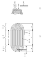
- FIG.1 (a) is sectional drawing of the electrode group of one Embodiment in the flat non-aqueous secondary battery concerning embodiment
- FIG.1 (b) is an expanded sectional view of a lamination electrode body.
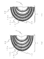
- FIG. 2 is a partial cross-sectional view of a corner portion of the electrode group.
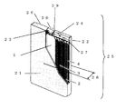
- FIG. 3 is a partially cutaway perspective view of the flat non-aqueous secondary battery according to the embodiment.
- Fig.4 (a) is a winding state figure of the electrode group concerning embodiment
- FIG.4 (b) is a winding state figure of a corner part
- FIG.4 (c) is a state diagram which sends in the same member.
- FIG. 4D is a winding state diagram of the straight portion.
- FIG. 5A is a cross-sectional view of an electrode group according to a pre-study example
- FIG. 5B is a partial cross-sectional view of an electrode group corner portion
- FIG. 6 is a manufacturing state diagram of an electrode group according to another preliminary study example.
- FIG. 5 shows an electrode group of a study example examined by the inventor of the present invention.
- the expansion amount of the electrode plate is measured in advance as shown in FIG.
- the spacer 108 is inserted in each winding layer with the gap 101 of the same size as in the above to form the gaps 101 at equal intervals.
- a part of the outermost periphery of the electrode assembly 100 is fixed by the winding stop tape 102, so that expansion 109 and expansion 110 occur even if the electrode plate expands during charging and discharging. Since it could not escape to the winding end side, it was difficult to absorb the full expansion amount because it always accumulated toward the winding start side.
- 5B shows the state in which the spacer 108 is pulled out of the electrode group 100.
- the corner portion 106 of the electrode group 100 is formed.
- the shape of the spacer 108 is transferred to the electrode plate 103, and is formed into a trapezoidal shape 105 having approximately two angular corners.
- the expansion 109 of the electrode plate 103 in the corner portion 106 of the electrode group 100 is absorbed by the gap formed by the spacer 108, but the expansion 110 in the long axis direction of the electrode plate 103 in the straight portion 107 is the corner portion
- the electrode plate 103 of 106 increases in thickness and expands 109.
- the expansion amount of the electrode group at the time of charge and discharge is measured, and the length of the straight portion and the length of the corner portion in the width of the electrode group are determined in consideration of the expansion amount so that this expansion amount can be absorbed.
- the electrode group is manufactured by winding, and then the hollow part inside the electrode group is expanded in the direction away from the axis of the electrode group, and the electrode group is compressed from the outside into a flat shape.
- Another prior study example to suppress the restoration to the shape of the shape was considered, but as shown in FIG. 6, when inserting the jig 112 into the hollow portion of the electrode group 100 and expanding it, the jig 112 and the electrode plate If the coefficient of friction with the member 111 such as a quality insulator is high, a problem arises that the member 111 is broken during production.
- FIG. 1 shows an electrode group 1 produced by winding a laminated electrode body 36 consisting of a porous insulator 4 and a negative electrode plate 2 and a positive electrode plate 3 three or more times.
- the electrode group 1 is provided with a long axis 5 and a flat plate-shaped straight portion 6 parallel to the long axis 5, and an apex 12 of each winding layer on the long axis 5 and connects the end of the straight portion 6 and the apex 12 by a curve. It comprises a pair of curved corner portions 7.
- the electrode group 1 is fixed by a terminal tape (fixing member, adhesive tape) 8 for stopping the loosening of the electrode plate.
- the expansion 10 of the straight portion 6 of the electrode plate and the expansion 9 of the corner 7 during charging and discharging are indicated by arrows.
- FIG. 2A is a partial cross section of the corner portion 7 of the electrode group 1.
- the corner portion 7 is provided with an apex 12 of each winding layer on the major axis 5, and the apex 12 and the end of the straight portion 6 are connected by a curve to form a curved shape, and the electrode plate of the corner portion 7 and the porous insulator The clearances 13a to 13c formed between them and 4 are shown.
- the gaps 13a to 13c are configured to be different in size, and further, the gap 13a on the inner circumferential side is larger, and the gap 13c is smaller on the outer circumferential side. It is composed of
- FIG. 4 shows a method of manufacturing the electrode group 1. Specifically, FIG. 4A shows a state diagram in which the laminated electrode body 36 is wound by the winding core 32.
- FIG. 4B shows a state diagram in which the laminated electrode body 36 is fed to the winding core 32 side when the laminated electrode body 36 is wound around the corner portion 7 of the winding core 32.
- FIG. 4C shows a winding state diagram immediately after the laminated electrode body 36 is fed.
- FIG. 4 (d) shows a state diagram in which the laminated electrode body 36 is wound around the straight portion 6 of the winding core 32.
- the laminated electrode body 36 composed of the negative electrode plate 2, the positive electrode plate 3 and the porous insulator 4 is sandwiched between the upper winding core 30 and the lower winding core 31 and wound clockwise.
- the core 32 is rotated a predetermined number of times to wind the laminated electrode body 36.
- the pushing roller 33 pushes the laminated electrode body 36 downward and pulls out the predetermined amount.
- the pinch roller 34 is closed, and the pressure roller 35 presses the laminated electrode body 36.
- the push roller 33 is returned to the initial position, and the pressure roller 35 is released downward to feed the laminated electrode body 36 to the core 32 side.
- FIG. 4D when winding the laminated electrode body 36 around the straight portion 6 in order to set the gap at the corner portion 7 of the electrode group 1, the member is pressed while pressing the straight portion 6 by the pressing roller 35 Take up the That is, the take-up tension and the withdrawal amount of the laminated electrode body 36 are adjusted by the pressing roller 35 and the pushing roller 33 to adjust the size of the gap.
- the electrode group 1 can be manufactured, and the gaps 13a to 13c can be provided between the winding layers of the corner portion 7.
- the above-described manufacturing method is an example, and the electrode group 1 of the present invention can be manufactured without being limited to this, as long as the gaps 13a to 13c are provided in the corner portion 7 of the electrode group 1.
- the positive electrode plate 3 is a planetary mixer in which a positive electrode active material, a conductive material and a binder are dispersed in a dispersion medium on one side or both sides of a positive electrode current collector having a thickness of 5 ⁇ m to 30 ⁇ m of aluminum or aluminum alloy foil or non-woven fabric. Etc. The positive electrode mixture paint mixed and dispersed by a dispersing machine is applied, dried and rolled.
- the positive electrode active material is, for example, lithium cobaltate and its modified product (such as lithium cobaltate in which aluminum or magnesium is solid-solved), lithium nickelate and its modified product (such as that in which some nickel is cobalt-substituted), There are lithium manganate and its modified products.
- the conductive material at this time for example, carbon black such as acetylene black, ketjen black, channel black, furnace black, lamp black, thermal black and the like, and various graphites are used singly or in combination.
- PVdF polyvinylidene fluoride
- PTFE polytetrafluoroethylene
- the negative electrode plate 2 is a rolled copper foil, an electrolytic copper foil, a copper fiber non-woven fabric having a thickness of 5 ⁇ m to 25 ⁇ m on one side or both sides of a negative electrode current collector
- a dispersing machine such as a planetary mixer
- various natural graphite and artificial graphite, silicon-based composite agents such as silicide, and various alloy composition materials can be used.
- various binders including PVdF and its modified product can be used as a binder for the negative electrode, but from the viewpoint of lithium ion acceptance improvement, styrene-butadiene copolymer rubber particles (SBR) and its modified product And so on.
- a thickener As a thickener, it is a material having viscosity as an aqueous solution such as polyethylene oxide (PEO) or polyvinyl alcohol (PVA), and a cellulose resin such as carboxymethyl cellulose (CMC) and its modified product are dispersed in a mixture paint It is preferable from the viewpoint of the viscosity and the viscosity.
- PEO polyethylene oxide
- PVA polyvinyl alcohol
- CMC carboxymethyl cellulose
- ethylene carbonate (EC), dimethyl carbonate (DMC), diethyl carbonate (DEC), and methyl ethyl carbonate (MEC) can be used alone or in combination as a solvent. It is also preferable to use vinylene carbonate (VC) or cyclohexylbenzene (CHB) and a modified product thereof in order to form a good film on the positive and negative electrode plates or to guarantee the stability during overcharge.
- VC vinylene carbonate
- CHB cyclohexylbenzene
- FIG. 3 is a perspective view of the flat non-aqueous secondary battery 25.
- the electrode assembly 1 and the insulating frame 27 are accommodated inside the bottomed flat battery case 21.
- a negative electrode lead 23 and a positive electrode lead 22 are provided on the upper part of the electrode group 1, the negative electrode lead 23 is connected to a terminal 20 having an insulating gasket 29 attached to the periphery, and the positive electrode lead 22 is connected to a sealing plate 26. ing.
- the sealing plate 26 is provided with a sealing plug 24. Further, at the central portion of the battery case 21, the thickness 28 of the battery is shown. More specifically, the electrode group 1 shown in FIG.
- the electrode frame 1 is pressurized in the thickness direction of the electrode group 1 to form a flat shape, and then, the electrode frame 1 is housed together with the insulating frame 27 inside the bottomed flat battery case 21.
- the negative electrode lead 23 led out from the upper part of the electrode group 1 is connected to the terminal 20 to which the insulating gasket 29 is attached at the periphery, and the positive lead 22 drawn out from the upper part of the electrode group 1 is connected to the sealing plate 26.
- the sealing plate 26 is inserted into the opening of the battery case 21, and the sealing plate 26 and the battery case 21 are welded and sealed along the outer periphery of the opening of the battery case 21.
- the sealing plug 24 After injecting a non-aqueous electrolyte (not shown) composed of a predetermined amount of non-aqueous solvent from the sealing plug into the battery case 21, the sealing plug 24 is welded to the sealing plate 26 to form a flat non-aqueous secondary battery 25.
- the said manufacturing method is an example and is not limited to this.
- Second Embodiment differs from the first embodiment only in that the size of the gap formed by winding the laminated electrode body 36 is different from that of the first embodiment, and the other configurations, materials and the like are the same as the first embodiment. Explain the part.
- the clearance 13d existing on the innermost side is the largest, and the clearance 13e and the clearance 13f of the respective wound layers are other than this. Is smaller than the gap 13d and has the same size.
- Example 1 In the first embodiment, as shown in FIG. 2A, in the corner portion 7 of the electrode group 1, the gap 13a on the inner peripheral side is large and the gaps 13b and 13c on the outer peripheral side are sequentially smaller.
- a flat non-aqueous secondary battery 25 was produced in which the thickness 28 of the battery shown in FIG. 3 is 6 mm, the width is 35 mm, and the height is 35 mm.
- an electrode plate 100 parts by weight of lithium cobaltate as a positive electrode active material, 2 parts by weight of acetylene black as a conductive material with respect to 100 parts by weight of active material, and 100 parts by weight of polyvinylidene fluoride as a binder
- a positive electrode mixture paint was produced by stirring and kneading 2 parts by weight with an appropriate amount of N-methyl-2-pyrrolidone using a double-arm type mixer.
- this positive electrode mixture paint was applied to both surfaces of a positive electrode current collector of aluminum foil having a thickness of 15 ⁇ m, and after drying, a positive electrode plate 3 was produced in which the thickness of the positive electrode mixture layer on one side was 100 ⁇ m. Furthermore, by pressing the positive electrode plate 21 so that the total thickness is 165 ⁇ m, a positive electrode mixture layer is formed on the positive electrode current collector of aluminum foil so that the thickness of one side of the positive electrode mixture layer is 75 ⁇ m. Thereafter, slit processing was performed to a width defined by the electrode group 1 for the flat non-aqueous secondary battery 25 shown in FIG. 1 to fabricate a positive electrode plate 3.
- this negative electrode mixture paint was applied to a negative electrode current collector of a copper foil having a thickness of 10 ⁇ m in the width direction, and after drying, a negative electrode plate 2 having a thickness of 100 ⁇ m on one side of the negative electrode mixture layer was produced. Further, the negative electrode plate 2 is pressed to a total thickness of 170 ⁇ m to form a negative electrode mixture layer on the negative electrode current collector so that the thickness of one side of the negative electrode mixture layer is 80 ⁇ m, The negative electrode plate 2 was fabricated by slitting to the width defined by the electrode group 1 for the flat non-aqueous secondary battery 25 shown in FIG.
- the laminated electrode body 36 composed of the negative electrode plate 2, the positive electrode plate 3 and the porous insulator 4 is sandwiched between the upper winding core 30 and the lower winding core 31 and wound clockwise.
- the core 32 was rotated to wind the laminated electrode assembly 36.
- the pushing roller 33 pushes the laminated electrode body 36 downward to push the laminated electrode body 36 by a predetermined amount. Pulled out.
- the pressing dimension of the roller 33 is set long, and the laminated electrode body 36 is drawn long. Then, this dimension is successively shortened toward the winding end side, and the amount of withdrawal of the laminated electrode body 36 is shortened.
- the gap 13a on the winding start side is large, and the gaps 13b and 13c on the winding end side are sequentially reduced.
- the pushing roller 33 is returned to the initial position, and the pressing roller 35 is released downward, and the laminated electrode body 36 is fed to the winding core 32 side.
- Example 2 In the second embodiment, as shown in FIG. 2B, in the corner portion 7 of the electrode group 1, the gap 13d on the winding start (inner periphery) side is large, and the sizes of the gaps 13e and 13f of the other winding layers are different. Was configured to be uniform.
- a flat non-aqueous secondary battery 25 was produced in which the thickness 28 of the battery shown in FIG. 3 is 6 mm, the width is 35 mm, and the height is 35 mm.
- the preparation of the electrode plate is the same as in Example 1. 100 parts by weight of lithium cobaltate as a positive electrode active material, 2 parts by weight of acetylene black as a conductive material to 100 parts by weight of active material, polyvinylidene fluoride as a binder
- the positive electrode mixture paint was prepared by stirring and kneading 2 parts by weight with 100 parts by weight of the active material together with a suitable amount of N-methyl-2-pyrrolidone using a double-arm type mixer.
- this positive electrode mixture paint was applied to both surfaces of a positive electrode current collector of aluminum foil having a thickness of 15 ⁇ m, and after drying, a positive electrode plate 3 was produced in which the thickness of the positive electrode mixture layer on one side was 100 ⁇ m. Furthermore, by pressing the positive electrode plate 21 so that the total thickness is 165 ⁇ m, a positive electrode mixture layer is formed on the positive electrode current collector of aluminum foil so that the thickness of one side of the positive electrode mixture layer is 75 ⁇ m. Thereafter, slit processing was performed to a width defined by the electrode group 1 for the flat non-aqueous secondary battery 25 shown in FIG. 1 to fabricate a positive electrode plate 3.
- this negative electrode mixture paint was applied to a negative electrode current collector of a copper foil having a thickness of 10 ⁇ m in the width direction, and after drying, a negative electrode plate 2 having a thickness of 100 ⁇ m on one side of the negative electrode mixture layer was produced. Further, the negative electrode plate 2 is pressed to a total thickness of 170 ⁇ m to form a negative electrode mixture layer on the negative electrode current collector so that the thickness of one side of the negative electrode mixture layer is 80 ⁇ m, The negative electrode plate 2 was fabricated by slitting to the width defined by the electrode group 1 for the flat non-aqueous secondary battery 25 shown in FIG.
- the laminated electrode body 36 composed of the negative electrode plate 2, the positive electrode plate 3 and the porous insulator 4 is sandwiched between the upper winding core 30 and the lower winding core 31 and wound clockwise.
- the core 32 was rotated to wind the laminated electrode assembly 36.
- the pushing roller 33 pushes the laminated electrode body 36 downward to push the laminated electrode body 36 by a predetermined amount. Pulled out.
- the pressing dimension of the roller 33 is set long and the laminated electrode body 36 is drawn long. Then, this dimension is set to be shorter than the winding start side, and the amount of withdrawal of the laminated electrode body 36 is made constant except for the winding start.
- the gap 13d on the winding start side is large, and the sizes of the gaps 13e and 13f of the other winding layers are uniform.
- the pushing roller 33 is returned to the initial position, and the pressing roller 35 is released downward, and the laminated electrode body 36 is fed to the winding core 32 side.
- Comparative example 1 In Comparative Example 1, the corner portion 106 of the electrode group 100 shown in FIGS. 5A and 5B has the electrode plate 103 of the corner portion 106 so that the size of the gap 101 becomes uniform. A spacer 108 having a uniform thickness was inserted and wound between them. Then, after the spacer 108 was inserted and folded, the spacer 108 was removed, and a gap 101 having an equal size was formed, and an electrode group 100 was produced. Then, the end tape 102 was affixed and fixed to the winding end of an electrode plate. The other configuration was the same as that of the first embodiment.
- a flat non-aqueous secondary battery 25 was produced in which the thickness 28 of the battery shown in FIG. 3 is 6 mm, the width is 35 mm, and the height is 35 mm.
- the electrode group 1 manufactured in the above-described Example 1 and Example 2 and Comparative Example 1 is housed together with the insulating frame 27 inside the bottomed flat battery case 21 shown in FIG.
- the derived negative electrode lead 23 is connected to a terminal 20 having an insulating gasket 29 attached to the periphery, and then the positive electrode lead 22 derived from the upper part of the electrode group 1 is connected to a sealing plate 26.
- the sealing plate 26 and the battery case 21 are welded and sealed along the outer periphery of the opening of the battery case 21, and a non-aqueous electrolyte (a predetermined amount of the non-aqueous solvent is After pouring the sealing plug 24, the sealing plug 24 is welded to the sealing plate 26 to produce a flat non-aqueous secondary battery 25.
- Example 2 and Comparative Example 1 100 electrode groups 1 are produced, 60 of which are produced as flat non-aqueous secondary batteries 25 and 40 are produced as battery cases. I left it in the state of putting. Each was evaluated as follows.
- the battery thickness immediately after preparation of the flat non-aqueous secondary battery 25 and the battery thickness after performing 500 times of charging / discharging (500 cycles) were measured, and these were compared.
- the first embodiment is configured such that the gap 13a on the inner peripheral side is large and the gap 13b and the gap 13c on the winding end become successively smaller. Since the expansion 9 is gradually absorbed by the gaps 13a, 13b, and 13c of different sizes that the expansion 9 on the outer peripheral side gradually accumulates toward the inside, the expansion 9 loses a place to go and the straight portion 6 It was considered that the increase in battery thickness was suppressed because it was not derived and the laminated electrode body 36 was not flexed.
- Example 2 As shown in FIG. 2B, the gap 13d on the winding start side is large, and the sizes of the gaps 13e and the gaps 13f of the other winding layers are uniform.
- the expansion 9 on the outer peripheral side has not been absorbed by the gaps 13 f and 13 e and accumulated toward the inside.
- the expansion 9 is absorbed by the clearance 13 d by setting the clearance 13 d on the inner circumferential side larger than the other clearances 13 e and the clearance 13 f, so the expansion 9 loses place and is derived in the straight portion 6. It was thought that the increase in battery thickness was suppressed because the laminated electrode body 36 was not flexed.
- Comparative Example 1 the increase in battery thickness after 500 cycles was larger than in Example 1 and Example 2, and the capacity retention rate was a low value of 73%.
- the gaps 101 of the corner portion 106 are uniformly set in each winding layer, but since the winding end side is fixed, expansion 109 can not be performed to the winding end side.
- the expansion 109 was considered to be cumulative toward the beginning side. For this reason, it is considered that a larger gap 101 is necessary toward the winding start (inner circumference) side, but here, since only the expansion amount of the electrode plate 103 is set for the gap 101 in each winding layer, the winding start side It is thought that the battery thickness increased due to the expansion 109 which had accumulated to lose its place in the corner portion 106 and escaped to the straight portion 107 to bend the electrode plate 103.
- the spacer 108 is inserted into the corner portion 106 shown in FIG. 5B to produce the gap 101, whereby the shape of the spacer 108 is transferred to the electrode plate.
- the straight portions 107 expand 110, it becomes extremely difficult to slide relative to each other because the electrode plates 103 contact each other at high pressure. Then, it was also considered that the expansion 110 of the straight portion 107 in the gap 101 could not be absorbed, and the expansion 110 lost the place to go, and the electrode plate 103 of the straight portion 107 bent to increase the battery thickness.
- the gaps 13a to 13c and the gaps 13d to 13f are provided in the electrode group 1 so that the inner circumferential side is large and the outer circumferential side is small, whereby the expansion 10 of the straight portion 6 at the time of charge and discharge and the expansion 9 of the corner portion 7 Can be absorbed by the gaps 13a to 13c and the gaps 13d to 13f, and it is possible to suppress the deflection of the electrode plate and the increase in battery thickness at the time of charge and discharge, and it is possible to suppress the decrease in battery capacity. Conceivable.
- the battery case may be a laminate container.
- a lamination container is a container which consists of a member which laminated a resin film on metal foil.
- the battery case can hold the laminated electrode body and function as a fixing member.
- each of the electrode groups comprises a winding portion having a straight portion parallel to the long axis direction of the cross section and a corner having a vertex on the long axis and connecting the vertex and the end of the straight portion Further, the winding start side of the gap formed between the electrode plate and the porous insulator at the corner portion of each winding layer from the winding start side to the winding end side of the electrode group is configured to be large at the winding end side.
- the deflection of the electrode plate is suppressed to suppress the increase in the thickness of the battery. And further the battery It is possible to suppress a decrease in, it is possible to provide a high flat-shaped nonaqueous secondary battery safety.
Landscapes
- Chemical & Material Sciences (AREA)
- Engineering & Computer Science (AREA)
- Manufacturing & Machinery (AREA)
- Chemical Kinetics & Catalysis (AREA)
- Electrochemistry (AREA)
- General Chemical & Material Sciences (AREA)
- Physics & Mathematics (AREA)
- Condensed Matter Physics & Semiconductors (AREA)
- General Physics & Mathematics (AREA)
- Inorganic Chemistry (AREA)
- Secondary Cells (AREA)
- Sealing Battery Cases Or Jackets (AREA)
Abstract
Description
図1は負極板2と正極板3とを多孔質絶縁体4からなる積層電極体36を3周以上巻回して作製した電極群1を示す。電極群1は、長軸5とこの長軸5に平行な平板形状のストレート部6と、長軸5上に各巻回層の頂点12を備えストレート部6の終端と頂点12とを曲線で結んだ湾曲した一対のコーナー部7とで構成される。また、電極群1は、電極板の緩みを止める終端テープ(固定部材、粘着テープ)8によって固定されている。また、充放電時における電極板のストレート部6の膨張10とコーナー7部の膨張9を矢印で示す。
実施形態2は積層電極体36を捲回した隙間の大きさが実施形態1と異なっているだけで、他の構成、材質等は実施形態1と同じであるので、実施形態1と異なっている部分を説明する。
実施例1は、電極群1のコーナー部7において、図2(a)に示すように内周側の隙間13aが大きく外周側の隙間13b、13cが順次小さくなるように構成した。
実施例2は、電極群1のコーナー部7において、図2(b)に示すように巻始め(内周)側の隙間13dが大きく、これ以外の各巻回層の隙間13e、13fの大きさが均一になるように構成した。
比較例1は、図5(a)と図5(b)に示す電極群100のコーナー部106が、隙間101の大きさが均一となるようにするために、コーナー部106の電極板103の間に均一な厚みを持つスペーサ108を差し込んで捲回した。そして、スペーサ108を差し入れたまま折り畳んだ後に、スペーサ108を取り除き等しい大きさの隙間101を形成し電極群100を作製した。その後、電極板の巻終わりに終端テープ102を貼り付けて固定した。それ以外は実施例1と同じ構成とした。

上記の実施形態・実施例は、本発明の例示であり、本発明はこれらの例に限定されない。公知技術や周知技術・慣用技術を上記の実施形態・実施例に適用してもよいし、当業者であれば容易に思いつく改変を加えても本発明の範囲に含まれる。電池ケースは、ラミネート容器であってもよい。ラミネート容器は、金属箔に樹脂フィルムをラミネートした部材からなる容器である。
2 負極板
3 正極板
4 多孔質絶縁体
5 長軸
6 ストレート部
7 コーナー部
8 終端テープ
9、10 膨張
12 頂点
13a~13f 隙間
20 端子
21 電池ケース
22 正極リード
23 負極リード
24 封栓
25 扁平形非水系二次電池
26 封口板
27 絶縁枠体
28 電池の厚み
29 絶縁ガスケット
30 上巻芯
31 下巻芯
32 巻芯
33 突きローラー
34 挟みローラー
35 押さえローラー
36 積層電極体
Claims (6)
- 正極活物質を備えた正極板と、
負極活物質を備えた負極板と、
前記正極板と前記負極板との間に配置される多孔質絶縁体と
を備え、
前記多孔質絶縁体を介在させて重ねられた前記正極板及び前記負極板からなる積層電極体は、3周以上捲回されて横断面が扁平な形状の電極群を形成しており、
前記電極群は、平板形状のストレート部と湾曲した一対のコーナー部とからなっており、
前記電極群は、固定部材によって緩まないように固定されており、
前記コーナー部において、前記積層電極体の隣り合う周の間のうち、少なくとも2つには隙間が存しており、
隣り合う少なくとも2つの前記隙間において、内周側の前記隙間の大きさは外周側の前記隙間の大きさよりも大きい関係を有する、扁平形非水系二次電池。 - 最も内周側に存する前記の隙間の大きさが、全ての隙間の大きさのなかで最も大きい、請求項1に記載されている扁平形非水系二次電池。
- 前記隙間が3つ以上存しており、最も内周側に存する前記隙間以外の隙間の大きさが、互いに実質的に同じである、請求項2に記載されている扁平形非水系二次電池。
- 前記隙間が3つ以上存しており、前記隙間の大きさは外周側から内周側に連れて大きくなっている、請求項2に記載されている扁平形非水系二次電池。
- 前記固定部材は、前記電極群を、非水電解液とともに封入する電池ケースである、請求項1に記載されている扁平形非水系二次電池。
- 前記固定部材は粘着テープである、請求項1に記載されている扁平形非水系二次電池。
Priority Applications (3)
| Application Number | Priority Date | Filing Date | Title |
|---|---|---|---|
| US13/394,258 US20120164503A1 (en) | 2010-07-30 | 2011-07-22 | Flat nonaqueous secondary battery |
| CN2011800039237A CN102511105A (zh) | 2010-07-30 | 2011-07-22 | 扁平形非水系二次电池 |
| JP2012503803A JPWO2012014422A1 (ja) | 2010-07-30 | 2011-07-22 | 扁平形非水系二次電池 |
Applications Claiming Priority (2)
| Application Number | Priority Date | Filing Date | Title |
|---|---|---|---|
| JP2010171645 | 2010-07-30 | ||
| JP2010-171645 | 2010-07-30 |
Publications (1)
| Publication Number | Publication Date |
|---|---|
| WO2012014422A1 true WO2012014422A1 (ja) | 2012-02-02 |
Family
ID=45529655
Family Applications (1)
| Application Number | Title | Priority Date | Filing Date |
|---|---|---|---|
| PCT/JP2011/004146 Ceased WO2012014422A1 (ja) | 2010-07-30 | 2011-07-22 | 扁平形非水系二次電池 |
Country Status (5)
| Country | Link |
|---|---|
| US (1) | US20120164503A1 (ja) |
| JP (1) | JPWO2012014422A1 (ja) |
| KR (1) | KR20120048666A (ja) |
| CN (1) | CN102511105A (ja) |
| WO (1) | WO2012014422A1 (ja) |
Cited By (6)
| Publication number | Priority date | Publication date | Assignee | Title |
|---|---|---|---|---|
| WO2019131628A1 (ja) * | 2017-12-26 | 2019-07-04 | Tdk株式会社 | 非水電解液二次電池 |
| WO2020031432A1 (ja) * | 2018-08-09 | 2020-02-13 | 株式会社村田製作所 | 二次電池、電池パック、電動車両、電力貯蔵システム、電動工具および電子機器 |
| WO2020031431A1 (ja) * | 2018-08-09 | 2020-02-13 | 株式会社村田製作所 | 二次電池、電池パック、電動車両、電力貯蔵システム、電動工具および電子機器 |
| JP2021009814A (ja) * | 2019-07-02 | 2021-01-28 | プライムアースEvエナジー株式会社 | 二次電池 |
| US10991969B2 (en) | 2014-08-18 | 2021-04-27 | Gs Yuasa International Ltd. | Energy storage device |
| JP2025016081A (ja) * | 2023-07-21 | 2025-01-31 | プライムプラネットエナジー&ソリューションズ株式会社 | 巻回電極体の製造方法、製造装置、および蓄電デバイス |
Families Citing this family (9)
| Publication number | Priority date | Publication date | Assignee | Title |
|---|---|---|---|---|
| JP6020929B2 (ja) * | 2013-09-09 | 2016-11-02 | トヨタ自動車株式会社 | 非水電解液二次電池 |
| CN108615924B (zh) | 2015-12-14 | 2021-04-27 | 东莞新能源科技有限公司 | 电芯及采用电芯的锂离子电池 |
| CN110277536B (zh) * | 2018-03-16 | 2023-01-10 | 株式会社理光 | 电极,绝缘层用涂布液,以及电极的制造方法 |
| CN110034338A (zh) * | 2019-04-24 | 2019-07-19 | 欣旺达电动汽车电池有限公司 | 一种改善锂离子电池层间间隙的方法 |
| US20230042891A1 (en) * | 2020-02-07 | 2023-02-09 | Sanyo Electric Co., Ltd. | Secondary battery |
| CN115039268B (zh) * | 2020-03-18 | 2024-12-10 | 宁德新能源科技有限公司 | 一种锂离子电池的电芯、其制备方法及包含其的锂离子电池 |
| CN113437443B (zh) * | 2021-06-21 | 2023-06-20 | 东莞新能安科技有限公司 | 电化学装置和电子装置 |
| CN116682936B (zh) * | 2023-08-04 | 2024-01-12 | 宁德时代新能源科技股份有限公司 | 电池及其制备方法、用电装置 |
| WO2025179555A1 (zh) * | 2024-02-29 | 2025-09-04 | 宁德时代新能源科技股份有限公司 | 电池单体、二次电池、用电装置、制备方法、计算机设备和计算机可读存储介质 |
Citations (6)
| Publication number | Priority date | Publication date | Assignee | Title |
|---|---|---|---|---|
| JP2003157888A (ja) * | 2001-11-26 | 2003-05-30 | Toshiba Corp | 平板状二次電池及びその製造方法 |
| JP2006107742A (ja) * | 2004-09-30 | 2006-04-20 | Sanyo Electric Co Ltd | 非水電解質二次電池とその製造方法 |
| JP2006164956A (ja) * | 2004-11-12 | 2006-06-22 | Sanyo Electric Co Ltd | 扁平渦巻電極体を備えた二次電池の製造方法 |
| JP2006244834A (ja) * | 2005-03-02 | 2006-09-14 | Sanyo Electric Co Ltd | 非水電解質二次電池 |
| JP2006278182A (ja) * | 2005-03-30 | 2006-10-12 | Sanyo Electric Co Ltd | 非水電解質二次電池とその製造方法 |
| JP2011090860A (ja) * | 2009-10-22 | 2011-05-06 | Panasonic Corp | 扁平形非水系二次電池 |
Family Cites Families (1)
| Publication number | Priority date | Publication date | Assignee | Title |
|---|---|---|---|---|
| CN100495802C (zh) * | 2004-11-12 | 2009-06-03 | 三洋电机株式会社 | 具有扁平螺旋电极体的二次电池的制造方法 |
-
2011
- 2011-07-22 CN CN2011800039237A patent/CN102511105A/zh active Pending
- 2011-07-22 JP JP2012503803A patent/JPWO2012014422A1/ja not_active Withdrawn
- 2011-07-22 US US13/394,258 patent/US20120164503A1/en not_active Abandoned
- 2011-07-22 KR KR1020127005450A patent/KR20120048666A/ko not_active Ceased
- 2011-07-22 WO PCT/JP2011/004146 patent/WO2012014422A1/ja not_active Ceased
Patent Citations (6)
| Publication number | Priority date | Publication date | Assignee | Title |
|---|---|---|---|---|
| JP2003157888A (ja) * | 2001-11-26 | 2003-05-30 | Toshiba Corp | 平板状二次電池及びその製造方法 |
| JP2006107742A (ja) * | 2004-09-30 | 2006-04-20 | Sanyo Electric Co Ltd | 非水電解質二次電池とその製造方法 |
| JP2006164956A (ja) * | 2004-11-12 | 2006-06-22 | Sanyo Electric Co Ltd | 扁平渦巻電極体を備えた二次電池の製造方法 |
| JP2006244834A (ja) * | 2005-03-02 | 2006-09-14 | Sanyo Electric Co Ltd | 非水電解質二次電池 |
| JP2006278182A (ja) * | 2005-03-30 | 2006-10-12 | Sanyo Electric Co Ltd | 非水電解質二次電池とその製造方法 |
| JP2011090860A (ja) * | 2009-10-22 | 2011-05-06 | Panasonic Corp | 扁平形非水系二次電池 |
Cited By (12)
| Publication number | Priority date | Publication date | Assignee | Title |
|---|---|---|---|---|
| US10991969B2 (en) | 2014-08-18 | 2021-04-27 | Gs Yuasa International Ltd. | Energy storage device |
| WO2019131628A1 (ja) * | 2017-12-26 | 2019-07-04 | Tdk株式会社 | 非水電解液二次電池 |
| WO2020031432A1 (ja) * | 2018-08-09 | 2020-02-13 | 株式会社村田製作所 | 二次電池、電池パック、電動車両、電力貯蔵システム、電動工具および電子機器 |
| WO2020031431A1 (ja) * | 2018-08-09 | 2020-02-13 | 株式会社村田製作所 | 二次電池、電池パック、電動車両、電力貯蔵システム、電動工具および電子機器 |
| JPWO2020031432A1 (ja) * | 2018-08-09 | 2021-04-30 | 株式会社村田製作所 | 二次電池、電池パック、電動車両、電力貯蔵システム、電動工具および電子機器 |
| JPWO2020031431A1 (ja) * | 2018-08-09 | 2021-05-13 | 株式会社村田製作所 | 二次電池、電池パック、電動車両、電力貯蔵システム、電動工具および電子機器 |
| JP7028331B2 (ja) | 2018-08-09 | 2022-03-02 | 株式会社村田製作所 | 二次電池、電池パック、電動車両、電力貯蔵システム、電動工具および電子機器 |
| US12034108B2 (en) | 2018-08-09 | 2024-07-09 | Murata Manufacturing Co., Ltd. | Secondary battery, battery pack, electric vehicle, electric power storage system, electric power tool, and electronic apparatus |
| US12095118B2 (en) | 2018-08-09 | 2024-09-17 | Murata Manufacturing Co., Ltd. | Secondary battery, battery pack, electric vehicle, electric power storage system, electric power tool, and electronic apparatus |
| JP2021009814A (ja) * | 2019-07-02 | 2021-01-28 | プライムアースEvエナジー株式会社 | 二次電池 |
| JP2025016081A (ja) * | 2023-07-21 | 2025-01-31 | プライムプラネットエナジー&ソリューションズ株式会社 | 巻回電極体の製造方法、製造装置、および蓄電デバイス |
| JP7827663B2 (ja) | 2023-07-21 | 2026-03-10 | プライムプラネットエナジー&ソリューションズ株式会社 | 巻回電極体の製造方法、製造装置、および蓄電デバイス |
Also Published As
| Publication number | Publication date |
|---|---|
| CN102511105A (zh) | 2012-06-20 |
| US20120164503A1 (en) | 2012-06-28 |
| KR20120048666A (ko) | 2012-05-15 |
| JPWO2012014422A1 (ja) | 2013-09-12 |
Similar Documents
| Publication | Publication Date | Title |
|---|---|---|
| WO2012014422A1 (ja) | 扁平形非水系二次電池 | |
| CN104008893B (zh) | 锂离子混合型电容器的制备方法及其锂离子混合型电容器 | |
| JP4513822B2 (ja) | 電極及び電気化学デバイス | |
| JP6024990B2 (ja) | 非水電解液二次電池の製造方法 | |
| CN108028362A (zh) | 用于锂离子二次电池的负极以及锂离子二次电池 | |
| CN102460778A (zh) | 锂二次电池 | |
| WO2013031012A1 (ja) | 非水電解質二次電池 | |
| JP7102831B2 (ja) | 正極及びリチウムイオン二次電池 | |
| EP4333153A1 (en) | Non-aqueous electrolyte secondary battery | |
| JP2018170250A (ja) | リチウムイオン二次電池用負極活物質、負極及びリチウムイオン二次電池 | |
| JP7115296B2 (ja) | 負極及びリチウムイオン二次電池 | |
| WO2011048769A1 (ja) | 扁平形二次電池用電極群及びその製造方法並びに扁平形二次電池用電極群を備えた扁平形二次電池 | |
| JP2020071959A (ja) | 二次電池及び二次電池の製造方法 | |
| JP2019164965A (ja) | リチウムイオン二次電池 | |
| JP7003775B2 (ja) | リチウムイオン二次電池 | |
| JP7409762B2 (ja) | 非水電解液二次電池および非水電解液二次電池の製造方法 | |
| JP2018160379A (ja) | リチウムイオン二次電池用負極およびリチウムイオン二次電池 | |
| JP2012059491A (ja) | 扁平形二次電池用電極群およびこれを用いた扁平形二次電池 | |
| EP3273511B1 (en) | Negative electrode for non-aqueous electrolyte secondary cell, and non-aqueous electrolyte secondary cell in which said negative electrode is used | |
| JP2002216768A (ja) | 非水二次電池 | |
| US20220311007A1 (en) | Positive electrode for lithium ion secondary battery and lithium ion secondary battery | |
| JP2013229320A (ja) | リチウムイオン二次電池 | |
| JP2022147190A (ja) | リチウムイオン二次電池用負極及びリチウムイオン二次電池 | |
| JP2011090860A (ja) | 扁平形非水系二次電池 | |
| JP2017098155A (ja) | 非水電解液二次電池の製造方法 |
Legal Events
| Date | Code | Title | Description |
|---|---|---|---|
| WWE | Wipo information: entry into national phase |
Ref document number: 201180003923.7 Country of ref document: CN |
|
| WWE | Wipo information: entry into national phase |
Ref document number: 2012503803 Country of ref document: JP |
|
| ENP | Entry into the national phase |
Ref document number: 20127005450 Country of ref document: KR Kind code of ref document: A |
|
| WWE | Wipo information: entry into national phase |
Ref document number: 13394258 Country of ref document: US |
|
| 121 | Ep: the epo has been informed by wipo that ep was designated in this application |
Ref document number: 11812024 Country of ref document: EP Kind code of ref document: A1 |
|
| NENP | Non-entry into the national phase |
Ref country code: DE |
|
| 122 | Ep: pct application non-entry in european phase |
Ref document number: 11812024 Country of ref document: EP Kind code of ref document: A1 |