WO2012014388A1 - 分注装置および核酸分析装置 - Google Patents
分注装置および核酸分析装置 Download PDFInfo
- Publication number
- WO2012014388A1 WO2012014388A1 PCT/JP2011/003847 JP2011003847W WO2012014388A1 WO 2012014388 A1 WO2012014388 A1 WO 2012014388A1 JP 2011003847 W JP2011003847 W JP 2011003847W WO 2012014388 A1 WO2012014388 A1 WO 2012014388A1
- Authority
- WO
- WIPO (PCT)
- Prior art keywords
- dispensing
- reagent
- lid
- nozzle
- dispensing nozzle
- Prior art date
- Legal status (The legal status is an assumption and is not a legal conclusion. Google has not performed a legal analysis and makes no representation as to the accuracy of the status listed.)
- Ceased
Links
Images





Classifications
-
- B—PERFORMING OPERATIONS; TRANSPORTING
- B67—OPENING, CLOSING OR CLEANING BOTTLES, JARS OR SIMILAR CONTAINERS; LIQUID HANDLING
- B67D—DISPENSING, DELIVERING OR TRANSFERRING LIQUIDS, NOT OTHERWISE PROVIDED FOR
- B67D7/00—Apparatus or devices for transferring liquids from bulk storage containers or reservoirs into vehicles or into portable containers, e.g. for retail sale purposes
- B67D7/02—Apparatus or devices for transferring liquids from bulk storage containers or reservoirs into vehicles or into portable containers, e.g. for retail sale purposes for transferring liquids other than fuel or lubricants
- B67D7/0288—Container connection means
-
- G—PHYSICS
- G01—MEASURING; TESTING
- G01N—INVESTIGATING OR ANALYSING MATERIALS BY DETERMINING THEIR CHEMICAL OR PHYSICAL PROPERTIES
- G01N35/00—Automatic analysis not limited to methods or materials provided for in any single one of groups G01N1/00 - G01N33/00; Handling materials therefor
- G01N35/10—Devices for transferring samples or any liquids to, in, or from, the analysis apparatus, e.g. suction devices, injection devices
- G01N35/1002—Reagent dispensers
-
- G—PHYSICS
- G01—MEASURING; TESTING
- G01N—INVESTIGATING OR ANALYSING MATERIALS BY DETERMINING THEIR CHEMICAL OR PHYSICAL PROPERTIES
- G01N35/00—Automatic analysis not limited to methods or materials provided for in any single one of groups G01N1/00 - G01N33/00; Handling materials therefor
- G01N2035/00178—Special arrangements of analysers
- G01N2035/00277—Special precautions to avoid contamination (e.g. enclosures, glove- boxes, sealed sample carriers, disposal of contaminated material)
-
- G—PHYSICS
- G01—MEASURING; TESTING
- G01N—INVESTIGATING OR ANALYSING MATERIALS BY DETERMINING THEIR CHEMICAL OR PHYSICAL PROPERTIES
- G01N35/00—Automatic analysis not limited to methods or materials provided for in any single one of groups G01N1/00 - G01N33/00; Handling materials therefor
- G01N35/02—Automatic analysis not limited to methods or materials provided for in any single one of groups G01N1/00 - G01N33/00; Handling materials therefor using a plurality of sample containers moved by a conveyor system past one or more treatment or analysis stations
- G01N35/04—Details of the conveyor system
- G01N2035/0401—Sample carriers, cuvettes or reaction vessels
- G01N2035/0403—Sample carriers with closing or sealing means
- G01N2035/0405—Sample carriers with closing or sealing means manipulating closing or opening means, e.g. stoppers, screw caps, lids or covers
-
- G—PHYSICS
- G01—MEASURING; TESTING
- G01N—INVESTIGATING OR ANALYSING MATERIALS BY DETERMINING THEIR CHEMICAL OR PHYSICAL PROPERTIES
- G01N35/00—Automatic analysis not limited to methods or materials provided for in any single one of groups G01N1/00 - G01N33/00; Handling materials therefor
- G01N35/10—Devices for transferring samples or any liquids to, in, or from, the analysis apparatus, e.g. suction devices, injection devices
- G01N35/1081—Devices for transferring samples or any liquids to, in, or from, the analysis apparatus, e.g. suction devices, injection devices characterised by the means for relatively moving the transfer device and the containers in an horizontal plane
Definitions
- the present invention relates to a dispensing device and a nucleic acid analyzer.
- Dispensing robots are often used to automatically send various liquids, such as reagents, samples, and specimens, set in the device to any location.
- a dispensing robot is a unit that drives two-dimensionally or three-dimensionally within a certain range of the device and automatically sucks and discharges liquid using a nozzle or tip attached to the tip (hereinafter referred to as a nozzle). . It is used in various devices such as various automatic analyzers.
- the liquid (hereinafter referred to as reagent) that must be sent is often expensive. For this reason, it is necessary to reduce the amount of reagent necessary for performing the analysis as much as possible. Further, in the case of a medical device or the like, it is necessary to display an error so that misdiagnosis does not occur when liquid feeding fails for some reason. Therefore, a method of detecting the liquid level, reducing the amount of the nozzle attached to the reagent, and minimizing the amount of reagent used is often employed. For the liquid level detection, a capacitance method using a nozzle as an electrode is often employed.
- liquid level detection can be performed for all containers with one liquid level detection function.
- electrostatic capacity type liquid level detection since the nozzle is used as an electrode, it is necessary to avoid contact of the nozzle with components other than the reagent. This is because when the nozzle contacts a component other than the reagent, the contacted component may be erroneously detected as a liquid level.
- the reagent In order to achieve both of the above two functions, the reagent must be shut off as much as possible while keeping the nozzle in contact with other than the reagent.
- the required degree of shielding from air and the method of shielding vary depending on the device because the components, characteristics, and usage environment of the reagents used are different. In some cases, it is necessary to cover the reagent container with air by blocking it. If the lid is attached, the nozzle and the lid come into contact with each other. Therefore, a separate mechanism for opening and closing the lid is required. In order to open and close the lid, it is necessary to add a new driving mechanism, which causes disadvantages such as a significant increase in cost, an increase in the size of the apparatus, and an increase in generated noise.
- the lid is made of a conductive elastic body and the liquid level is detected after penetrating the lid with a nozzle.
- the reagent adhering to the nozzle during reagent aspiration also adheres to the lid.
- the reagent that has adhered to the lid before that time adheres to the base of the nozzle.
- Pure water is often used for nozzle cleaning.
- the capacity of pure water set in the apparatus increases, and the capacity of the container for storing waste liquid increases accordingly, resulting in an increase in size of the apparatus.
- the cleaning from the root increases the capacity of pure water that adheres to the nozzle, and there is a drawback that it is diluted by the pure water that adheres to the nozzle during reagent aspiration.
- the problem to be solved is to provide a dispensing device and a nucleic acid analyzer that can simultaneously cover a reagent container while preventing cross-contamination between reagents.
- the dispensing device of the present invention includes a dispensing nozzle that sucks and discharges liquid, a protruding portion that protrudes below the dispensing nozzle, and a drive unit that drives the dispensing nozzle and the protruding portion in the vertical direction. And the dispensing nozzle is driven in the vertical direction independently of the protrusions.
- FIG. 4 is an outline of the nucleic acid analyzer (nucleic acid analyzer) of the present invention.
- the reagent in each of the reagent containers 11 and 13 arranged in the temperature control reagent rack 14 is sucked by the dispensing robot 9 and injected into the specimen sample plate 18 from the reagent inlet 15.
- the dispensing robot (dispensing mechanism) 9 includes a Z-axis drive unit 21 and a dispensing nozzle 10.
- the specimen sample plate 18 is fixed and temperature-controlled by a temperature control holder 19 to promote a chemical reaction.
- the specimen sample plate 18 fixed to the temperature control holder 19 is transported into the optical base 16 by the transport stage 20.
- both the capacitance type liquid level detection, the evaporation of the reagent, and the prevention of the deterioration of the chemical component are carried out without providing a new drive unit and software. This will be specifically described below.
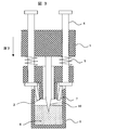
- FIG. 1 is a schematic view showing a dispensing mechanism and a reagent container of the present invention.
- the dispensing mechanism includes a dispensing nozzle 10 fixed to the Z drive base 1, a shaft 4 provided around the dispensing nozzle 10 so as to be able to drive inside the Z drive base 1, and a tip of the shaft 4. And a provided lid opening / closing component 3.
- a spring 5 is disposed along the shaft 4 between the Z drive base 1 and the lid opening / closing component 3. Further, the lid opening / closing member 3 has a tip protruding below the tip of the dispensing nozzle 10. Further, the lid opening / closing member 3 has a hollow cylindrical shape inside, and the dispensing nozzle 10 is located in this hollow portion.
- the shaft 4 connects the Z-axis drive base 1 and the lid opening / closing member 3, and the Z-axis drive base 1 can be driven along the shaft 4 in the Z-axis direction.
- the reagent container 6 is provided with a superelastic lid 7 with a cut.
- the dispensing mechanism moves downward toward the reagent container.
- the lid opening / closing member 3 enters the reagent container while pushing the lid 7 of the reagent container 6 open.
- the spring 5 that fixes the lid opening / closing component 3 bends to stop at the position where the lid 7 is pushed open.
- the dispensing nozzle 10 can suck the reagent 8 without contacting the lid 7.
- the lid 7 returns to its original position due to the elasticity of the lid 7 itself, and shuts off the reagent 8 and air. Further, the lid opening / closing component 3 returns to its original position due to friction between its own weight and the lid 7.
- FIG. 5 is an embodiment different from FIG. 1 showing details of the Z-axis drive unit 21 of the dispensing robot (dispensing mechanism) 9.
- the Z drive unit includes a Z axis drive base 22, and two shafts 25 pass through the Z axis drive base 22, and shaft fixing members 41 are provided on both sides of these shafts 25. It has been.
- the shaft fixing member 41 holds a shaft pressing member 43 having a rotating portion 42 at the tip, a spring 44 that presses the shaft pressing member 43 against the shaft 25 in the horizontal direction, and the shaft pressing member 43 and the spring 44.
- a housing 45 and a torsion spring 46 that presses the housing 45 downward are provided.
- the torsion spring 46 is fixed to the Z-axis drive base 22.
- the upper side of the shaft has a portion that gradually increases as the diameter approaches the upper side, and then returns to the original diameter, and further includes a weight 48 at the tip. As shown in FIG. 5, the shaft pressing member 43 presses the upper end of the portion having the largest diameter from above. The weight 48 presses the shaft 25 from above to below.
- a lid opening / closing member 26 is provided at the lower end of the shaft 25, and a dispensing nozzle 10 is provided between the shafts 25.
- the point that the lid 38 of the reagent container 37 is cut is the same as in the first embodiment.
- the lid opening / closing component 26 When the Z-axis drive base 22 is lowered from the initial position in FIG. 5, the lid opening / closing component 26 first contacts the lid 38.
- the lid opening / closing component 26 is fixed to the shaft 25, and a load is applied to the shaft 25 by a torsion spring 46. Therefore, the lid 38 is pushed open by the load (FIG. 6).
- the shaft fixing member 41 gets over the portion where the diameter of the shaft 25 is large, leaves the shaft 25, and the load on the shaft 25 is released.
- the dispensing nozzle 27 has a capacitance type liquid level detection function. After detecting the liquid level of the reagent 39, the dispensing nozzle 27 is lowered by a certain amount and sucks the reagent 39. After the reagent 39 is aspirated, the Z-axis drive base 22 rises (FIG. 8). As it rises, the lid opening / closing component 26 moves away from the cage of the reagent container 37 and returns to its original position due to its own weight due to the weight 48 and friction with the lid 38 (FIG. 5). The lid 38 also returns to its original position due to its own elasticity and friction with the lid opening / closing component 26.
- the reagent 39 does not adhere to the base of the dispensing nozzle 10 through the lid 38, it is possible to prevent contamination, simplify the cleaning of the dispensing nozzle 27, shorten the cleaning time, and reduce the amount of cleaning liquid. Furthermore, by disposing the torsion spring 46 for applying a load on the upper portion of the Z-axis drive base 22, the reagent does not adhere to the torsion spring 46 due to any beat.
- the torsion spring 46 for applying a load may be a push spring or a tension spring.
- a push spring or a pulling spring is used and the bottom of the reagent container 37 is deep, when the reagent 39 is sucked from the reagent container 37, the amount of deflection of the spring increases and the load on the Z-axis drive base 22 is reduced. It will increase.
- the load on the shaft 25 is eliminated when a certain amount of deflection is exceeded, so that it is possible to deal with the reagent container 37 having a deep bottom.
- the lid 38 will not close even if the load on the shaft 25 is removed.
- the structure can be simplified by using a push spring or a pull spring.
- the lid 38 may be opened / closed only by its own weight.
- the reagent container 37 may be lifted together when the nozzle 27 is lifted after the reagent is sucked.
- the torsion spring 46 of this structure is used as a push spring, a tension spring, or the like, and a load is always applied to the reagent container 37, so that the reagent container 37 can be prevented from rising.
- the device In each device with a dispensing robot, the device must have a lid on the reagent container to prevent reagent evaporation and chemical component deterioration. Capacitance type liquid level detection and contamination prevention, simplification of cleaning, and other reasons that must keep the lid and nozzle in non-contact. At this time, the original motion of the dispensing robot is utilized, and a new drive mechanism and software are not provided, and the original motion of the dispensing robot is not limited.
- each device that has a dispensing robot there is a possibility that the reagent container may rise when the reagent is aspirated, and it is necessary to prevent it.
- the dispense robot is equipped with a function to prevent lifting.
- the dispensing robot is equipped with a function for detecting the presence or absence of a reagent container.
- the lid of the reagent container and the nozzle non-contact it is possible to detect the capacitance level, prevent evaporation of the reagent, and deterioration of chemical components. Thereby, the reliability of the reagent aspiration and the reliability of the analysis result are improved. Further, since the nozzle and the lid are not in contact with each other, it is possible to prevent the reagent from adhering to the nozzle through the lid. This prevents contamination, simplifies nozzle cleaning, shortens cleaning time, and reduces system water required for nozzle cleaning.
- the reagent lid can be opened and closed without adding a new drive mechanism, so that the cost can be reduced, the space can be secured, and the generated noise can be reduced. Furthermore, since the lid is opened and closed using only the vertical movement of the dispensing robot, there is no restriction on the original movement of the dispensing robot. In addition, since the lid opening / closing mechanism is mounted on the dispensing robot, even if the number of reagent containers is increased, only one lid opening / closing component is required, so that it is easy to cope with an increase in reagent types.
Landscapes
- Analytical Chemistry (AREA)
- Physics & Mathematics (AREA)
- Health & Medical Sciences (AREA)
- Life Sciences & Earth Sciences (AREA)
- Chemical & Material Sciences (AREA)
- Biochemistry (AREA)
- General Health & Medical Sciences (AREA)
- General Physics & Mathematics (AREA)
- Immunology (AREA)
- Pathology (AREA)
- Mechanical Engineering (AREA)
- Engineering & Computer Science (AREA)
- Automatic Analysis And Handling Materials Therefor (AREA)
Abstract
試薬間のクロスコンタミネーションを防止しつつ、試薬容器に蓋を付けることの両立を行う分注装置を提供する。 本発明の分注装置は、液体を吸引および吐出する分注ノズル10と、分注ノズル10よりも下方に突出した蓋開閉部品26と、分注ノズル10および蓋開閉部品26を垂直方向へ駆動させる駆動部と、を備え、分注ノズル10が蓋開閉部品26とは独立して垂直方向へ駆動する。試薬間のクロスコンタミネーションを防止しつつ、試薬容器に蓋を付けることの両立を行う分注装置を提供することができる。
Description
本発明は、分注装置および核酸分析装置に関する。
試薬・サンプル・検体等、装置にセットされた様々な液体を任意の場所に自動で送液するために、分注ロボットが使われることが多い。分注ロボットとは、装置の一定範囲内を2次元、もしくは3次元に駆動させ、先端に付いたノズルやチップ等(以下ノズルとする)にて液体の吸引・吐出を自動で行うユニットである。各種自動分析装置等、様々な装置にて使われている。
各種自動分析装置等において、送液しなければならない液体(以後試薬とする)は高価なものが多い。そのため、分析を行うために必要な試薬の使用量をなるべく少なくする必要がある。また、医療機器等の場合、何らかの原因で送液に失敗した時に、誤診に繋がらないようにエラーを表示させる必要がある。そこで、液面検知を行い、ノズルが試薬に付着する量を少なくし、試薬の使用量を最小限に抑える方式がよく採用されている。液面検知は、ノズルを電極とした静電容量方式がよく採用されている。この方式を採用することで、試薬の入った容器の数が増えても、1つの液面検知機能で全ての容器に対して液面検知を行うことができる。静電容量方式の液面検知を行う際、ノズルを電極とするため、ノズルが試薬以外の部品と接触することを避ける必要がある。ノズルが試薬以外の部品に接触した時に、その接触した部品を液面だと誤検知してしまう恐れがあるからである。
一方、各種自動分析装置等において、装置に長い時間試薬をセットしておかなければならないことがある。装置に長い時間試薬をセットしておくと、試薬の蒸発・化学成分の劣化等は避けることができない。しかし、試薬の使用量を減らせば減らすほど、試薬の蒸発・化学成分の劣化の影響は大きくなる。そうすると、解析結果の信頼性が損なわれてしまう恐れがある。試薬の蒸発・化学成分の劣化を防ぐためには、試薬を冷却する方法の他に、空気と遮断しなければならない。
上記2つの機能を両立するためには、ノズルは試薬以外と非接触にしつつ、試薬は空気となるべく遮断しなければならない。必要な空気との遮断の程度や遮断の方法に関しては、使用する試薬の成分や特性,使用環境が違うため装置によって異なる。場合によっては試薬容器に蓋を付けて空気とより遮断する必要が出てくる。蓋を付けるとノズルと蓋が接触してしまうため、静電容量方式の液面検知では誤検知する恐れがある。そのため、蓋を開閉するための機構が別に必要となる。蓋を開閉するためには新たな駆動機構の追加も余儀なくされるため、それによりコストの大幅アップ,装置サイズ大型化,発生ノイズの増加等の欠点が出てくる。
この改善策として、蓋を導電性の弾性体にし、ノズルで蓋を貫通させてから液面検知を行うという方法がある。だが、試薬吸引の際にノズルに付着した試薬が蓋にも付着してしまう。再度その試薬を吸引する際に、その前に蓋に付着した試薬がノズルの根元まで付着してしまう。これにより、試薬間のクロスコンタミネーション(別々の試薬同士が混合されてしまう)の増加が懸念される。それを解決させるためには、ノズル洗浄の際、ノズルを根元から洗浄を行う必要がある。
ノズルの洗浄には純水を使用することが多い。使用する純水の量が増えると、装置にセットしておく純水の容量が増加し、その分廃液を溜める容器の容量も増加してしまい装置が大型化してしまう。また、根元から洗浄を行うことで、ノズルに付着する純水の容量が増えてしまい、試薬吸引時にノズルに付着した純水により希釈されてしまうといった欠点がある。
解決しようとする課題は、試薬間のクロスコンタミネーションを防止しつつ、試薬容器に蓋を付けることの両立を行う分注装置および核酸分析装置を提供することである。
本発明の分注装置は、液体を吸引および吐出する分注ノズルと、該分注ノズルよりも下方に突出した突起部と、分注ノズルおよび突起部を垂直方向へ駆動させる駆動部と、を備え、分注ノズルが突起部とは独立して垂直方向へ駆動する。
試薬間のクロスコンタミネーションを防止しつつ、試薬容器に蓋を付けることの両立を行う分注装置および核酸分析装置を提供することができる。
図4は、本発明の核酸解析装置(核酸分析装置)の概要である。温度調節試薬ラック14に配置された各試薬容器11,13内の試薬を分注ロボット9にて吸引し、試薬注入口15から標本試料プレート18へ注入する。分注ロボット(分注機構)9は、Z軸駆動ユニット21と分注ノズル10とを備えている。
一部の試薬は試薬混合容器12にて数種類混合してから注入する。標本試料プレート18は温度調節ホルダ19にて固定及び温度調節をされ、化学反応を促進させる。
その後、温度調節ホルダ19に固定された標本試料プレート18は搬送ステージ20にて光学ベース16の中に搬送される。
CCDカメラユニット17内部の光源(不図示)により発せられた光を光学ベース16内に搬送された標本試料プレート18へ照射することにより、標本試料プレート18から蛍光を発し、それをCCDカメラユニット17内部のCCDカメラ(不図示)で撮影する。撮影された画像を元に核酸の解析を行う。
本発明は、静電容量方式の液面検知,試薬の蒸発・化学成分の劣化防止の両立を、新たな駆動部、ソフトを設けずに実施した。以下、具体的に説明する。
図1は本発明の分注機構および試薬容器を示す概略図である。
分注機構は、Z駆動ベース1に固定された分注ノズル10と、分注ノズル10の周りに設けられZ駆動ベース1の内部を駆動可能に貫通したシャフト4と、このシャフト4の先端に設けられた蓋開閉部品3とを備える。
Z駆動ベース1と蓋開閉部品3の間には、シャフト4に沿ってバネ5が配置されている。また、蓋開閉部材3は、その先端が分注ノズル10の先端よりも下方へ突出している。さらに、蓋開閉部材3は、内部が中空の円柱形状であり、この中空部分に分注ノズル10が位置する。シャフト4は、Z軸駆動ベース1と蓋開閉部材3とを連結しており、Z軸駆動ベース1がこのシャフト4に沿ってZ軸方向へ駆動可能である。
また、試薬容器6には、切り込みが入った超弾性体の蓋7が設けられている。
次に、この分注機構の分注動作について説明する。
まず、分注機構が試薬容器に向かって下方へ移動する。図2に示すように、蓋開閉部材3が試薬容器6の蓋7を押し開けつつ、試薬容器内へ進入する。Z駆動ベース1がさらに降下すると、蓋開閉部品3を固定しているバネ5がたわむことで、蓋7を押し開けた位置で止まる。それにより、図3に示すように、分注ノズル10が蓋7と接触することなく試薬8を吸引することが可能となる。試薬8吸引後、分注ノズル10が上昇すると、蓋7は蓋7自身の弾性により元の位置に戻り、試薬8と空気を遮断する。また、蓋開閉部品3は自重と蓋7との摩擦により元の位置に戻る。
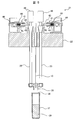
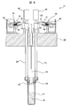
図5は、分注ロボット(分注機構)9のZ軸駆動ユニット21の詳細を示した図1とは別の実施例である。
Z駆動ユニットについて説明する。Z駆動ユニットは、Z軸駆動ベース22を備えており、Z軸駆動ベース22の内部には、2本のシャフト25が貫通しており、これらのシャフト25の両脇にシャフト固定部材41が設けられている。シャフト固定部材41は、先端に回転部42を備えたシャフト押圧部材43と、このシャフト押圧部材43を水平方向へシャフト25に対して押し付けるバネ44と、これらシャフト押圧部材43及びバネ44を保持する筐体45と、筐体45を下方へ押し付けるねじりバネ46とを備えている。ねじりバネ46は、Z軸駆動ベース22に固定されている。
次に、シャフト25の上方側の形状について説明する。シャフトの上方側は、径が上方に近づくにつれて徐々に多くなり、その後元の径の大きさに戻る箇所を有しており、さらにその先に重り48を備えている。シャフト押圧部材43は、図5に示すように、径が最も多くなった箇所の上端を上方から押さえつけている。重り48は、シャフト25を上方から下方へ押さえつけている。
また、実施例1と同様に、シャフト25の下端には蓋開閉部材26が設けられており、シャフト25間には、分注ノズル10が設けられている。なお、試薬容器37の蓋38に切り込みが入っている点は実施例1と同様である。
次に動作を図5~図8を用いて説明する。
図5の初期位置からZ軸駆動ベース22が下降すると、まず蓋38に蓋開閉部品26が接触する。蓋開閉部品26はシャフト25に固定されており、シャフト25はねじりバネ46で荷重がかけられているため、その荷重にて蓋38を押し開く(図6)。
Z軸駆動ベース22がさらに降下すると、蓋開閉部品26は試薬容器37の淵に接触して止まるため、ねじりバネ46がたわみ、分注ノズル10のみが降下していく(図7)。
ねじりバネ46は、一定のたわみ量を超えたら、シャフト固定部材41がシャフト25の径が大きくなっている箇所を乗り越え、シャフト25から離れ、シャフト25への荷重が解除される。
分注ノズル27には静電容量方式の液面検知機能が備わっており、試薬39の液面を検知してから一定量降下し、試薬39の吸引を行う。試薬39吸引後、Z軸駆動ベース22が上昇する(図8)。上昇していくと、蓋開閉部品26は試薬容器37の淵から離れ、重り48による自重と、蓋38との摩擦により元の位置に戻る(図5)。蓋38も、自身の弾性と蓋開閉部品26との摩擦により元の位置に戻る。
本形態を取ることで、試薬39吸引の際に分注ノズル10と試薬容器37の蓋38を非接触にしつつ、吸引時以外は試薬容器37中の試薬39を空気と遮断することが可能となる。それにより静電容量方式の液面検知と試薬39の蒸発・化学成分の劣化防止の両立が可能となり、試薬吸引の信頼性・解析結果の信頼性が向上する。
また、蓋38を通じて試薬39が分注ノズル10の根元まで付着することが無いため、コンタミネーションの防止,分注ノズル27洗浄の簡略化,洗浄時間短縮,洗浄液量の低減が図れる。さらに、荷重をかけるためのねじりバネ46をZ軸駆動ベース22の上部に配置することで、何かの拍子でねじりバネ46に試薬が付着することが無いようになる。
荷重をかけるためのねじりバネ46は押しバネや引きバネでも良い。ただし、押しバネや引きバネを採用した場合、試薬容器37の底が深い場合は、試薬容器37から試薬39を吸引する際、バネのたわみ量が大きくなり、Z軸駆動ベース22への荷重が増大してしまう。
ねじりバネ46を採用した本構造にすることで、一定のたわみ量を超えるとシャフト25への荷重が無くなるため、底が深い試薬容器37にも対応できる。本発明を一度開ききった蓋38はシャフト25への荷重を無くしても閉じることは無い。しかしながら、試薬容器37の底が浅い場合は、押しバネや引きバネを使用した方が構造を簡略化できる。また、重り48を大きくして蓋38を開けることができる重さにすることが可能であれば、重り48の自重のみで蓋38を開閉しても良い。
本構造を応用することで、蓋38を開閉すること以外のことも可能となる。仮に蓋38を開閉せず、貫通させて試薬39の吸引を行う際、試薬の吸引後ノズル27を上昇させる際に試薬容器37も一緒に持ち上げてしまう恐れがある。それに対し、本構造のねじりバネ46を押しバネや引きバネ等にし、常に試薬容器37に荷重を与えることで、試薬容器37の浮き上がりを防止することができる。
さらに、本構造のシャフト25や重り48に検知板を付け、その検知板をセンサーで認識することで、試薬容器37の有無を判別することができ、顧客の試薬セット忘れを防止することができる。
これらの機能を温度調節試薬ラック14側に設けると、試薬容器の数分だけセンサーや機構が必要となる。だが、本発明によりこれらの機能を分注ユニット9側に設けることでいくら試薬容器の数が増えても一つのセンサー,一つの機構で対応が可能となる。
分注ロボットを有する各装置において、試薬の蒸発・化学成分の劣化防止のために試薬容器に蓋を付け無ければならない装置。また、静電容量方式の液面検知やコンタミネーションの防止,洗浄の簡略化,その他の理由により、蓋とノズルを非接触にしなければならない装置。この時、分注ロボット本来の動きを利用し、新たな駆動機構,ソフトを設けず、分注ロボット本来の動きにも制限をかけること無く実現することを特徴とする。
分注ロボットを有する各装置において、試薬吸引時に試薬容器が浮き上がってしまう恐れがあり、それを防止する必要がある装置。浮き上がり防止のための機能を分注ロボットに搭載していることを特徴とする。
分注ロボットを有する各装置において、試薬容器の有無を検知する必要のある装置。試薬容器の有無の検知機能を分注ロボットに搭載していることを特徴とする。
本発明により試薬容器の蓋とノズルを非接触にすることで、静電容量方式の液面検知と試薬の蒸発・化学成分の劣化防止が可能になる。それにより、試薬吸引の信頼性・解析結果の信頼性が向上する。また、ノズルと蓋を非接触にしたことで、蓋を通じてノズルに試薬が付着することを防げる。これによりコンタミネーションの防止,ノズル洗浄の簡略化,洗浄時間短縮,ノズル洗浄に必要なシステム水の低減が図れる。
本発明の構造では、試薬の蓋開閉を新たな駆動機構を追加せずに行うことができるため、原価低減・スペースの確保・発生ノイズの低減が図れる。さらに、分注ロボットの持っている上下運動のみを使用して蓋を開閉するため、分注ロボット本来の動きに制限を与えることが無い。また、蓋開閉機構を分注ロボットに乗せたことにより、試薬容器の数が増えても蓋開閉部品は一つで済むため、試薬種類の増加に対する対応が容易である。
1 Z軸駆動ベース
3,26 蓋開閉部品
4,25 シャフト
5,44 バネ
6,11,13 試薬容器
7 蓋
8 試薬
9 分注ロボット
10 分注ノズル
12 試薬混合容器
14 温度調節試薬ラック
15 試薬注入口
16 光学ベース
17 CCDカメラユニット
18 標本試料プレート
19 温度調節ホルダ
20 搬送ステージ
21 Z軸駆動ユニット
22 Z軸駆動ベース
41 シャフト固定部材
42 回転部
43 シャフト押圧部材
45 筐体
46 ねじりバネ
48 重り
3,26 蓋開閉部品
4,25 シャフト
5,44 バネ
6,11,13 試薬容器
7 蓋
8 試薬
9 分注ロボット
10 分注ノズル
12 試薬混合容器
14 温度調節試薬ラック
15 試薬注入口
16 光学ベース
17 CCDカメラユニット
18 標本試料プレート
19 温度調節ホルダ
20 搬送ステージ
21 Z軸駆動ユニット
22 Z軸駆動ベース
41 シャフト固定部材
42 回転部
43 シャフト押圧部材
45 筐体
46 ねじりバネ
48 重り
Claims (9)
- 液体を吸引および吐出する分注ノズルと、該分注ノズルよりも下方に突出した突起部と、分注ノズルおよび突起部を垂直方向へ駆動させる駆動部と、を備え、分注ノズルが突起部とは独立して垂直方向へ駆動することを特徴とする分注装置。
- 突起部は、内部が中空の円柱部材であり、中空部分に分注ノズルが収容されていることを特徴とする請求項1に記載の分注装置。
- 突起部は、試薬容器の蓋を押し開けることを特徴とする請求項1に記載の分注装置。
- 垂直方向へ駆動する駆動ベースと、該駆動ベース内を貫通するシャフトと、シャフトを下方から所定の力が加わるまで下方へ押圧する押圧部材と、をさらに備え、
シャフトの先端に上記突起部が設けられ、駆動ベースに上記分注ノズルが固定されていることを特徴とする請求項1に記載の分注装置。 - 押圧部材は、ねじりバネを備えていることを特徴とする請求項4に記載の分注装置。
- シャフトは他の箇所よりも径が大きい箇所が設けられていることを特徴とする請求項1に記載の分注装置。
- シャフトの上端側には重りが備えられていることを特徴とする請求項6に記載の分注装置。
- 分注ノズルの先端には、液面検知機能が備わっていることを特徴とする請求項1に記載の分注装置。
- 液体を吸引および吐出する分注ノズルと、該分注ノズルよりも下方に突出した突起部と、分注ノズルおよび突起部を垂直方向へ駆動させる駆動部と、を備え、分注ノズルが突起部とは独立して垂直方向へ駆動する分注機構と、
試薬およびサンプルを流す流路を有するフローセルと、
フローセルへ励起光を照射する光源と、
フローセル上の蛍光を観察する撮像部と、を備えた、核酸分析装置。
Priority Applications (1)
| Application Number | Priority Date | Filing Date | Title |
|---|---|---|---|
| US13/811,940 US9114970B2 (en) | 2010-07-29 | 2011-07-06 | Dispensing device and nucleic acid analyzer |
Applications Claiming Priority (2)
| Application Number | Priority Date | Filing Date | Title |
|---|---|---|---|
| JP2010-169968 | 2010-07-29 | ||
| JP2010169968A JP5216820B2 (ja) | 2010-07-29 | 2010-07-29 | 分注装置および核酸分析装置 |
Publications (1)
| Publication Number | Publication Date |
|---|---|
| WO2012014388A1 true WO2012014388A1 (ja) | 2012-02-02 |
Family
ID=45529625
Family Applications (1)
| Application Number | Title | Priority Date | Filing Date |
|---|---|---|---|
| PCT/JP2011/003847 Ceased WO2012014388A1 (ja) | 2010-07-29 | 2011-07-06 | 分注装置および核酸分析装置 |
Country Status (3)
| Country | Link |
|---|---|
| US (1) | US9114970B2 (ja) |
| JP (1) | JP5216820B2 (ja) |
| WO (1) | WO2012014388A1 (ja) |
Cited By (2)
| Publication number | Priority date | Publication date | Assignee | Title |
|---|---|---|---|---|
| JP2014145693A (ja) * | 2013-01-30 | 2014-08-14 | Hitachi High-Technologies Corp | 核酸分析装置 |
| CN109696556A (zh) * | 2017-10-24 | 2019-04-30 | 豪夫迈·罗氏有限公司 | 移液装置和移液装置定位系统 |
Families Citing this family (2)
| Publication number | Priority date | Publication date | Assignee | Title |
|---|---|---|---|---|
| WO2015060316A1 (ja) * | 2013-10-22 | 2015-04-30 | 株式会社日立ハイテクノロジーズ | 自動分析装置 |
| JP6614048B2 (ja) * | 2016-06-28 | 2019-12-04 | 株式会社島津製作所 | 前処理装置 |
Citations (5)
| Publication number | Priority date | Publication date | Assignee | Title |
|---|---|---|---|---|
| JPS59638A (ja) * | 1982-06-26 | 1984-01-05 | Toshiba Corp | サンプリングユニツト |
| JPS643565A (en) * | 1987-06-25 | 1989-01-09 | Yasunobu Tsukioka | Method and device for taking and transferring reaction bead after cleaning in inspection of blood or the like |
| JP2005181145A (ja) * | 2003-12-19 | 2005-07-07 | Hitachi High-Technologies Corp | 核酸分析装置 |
| JP2005189034A (ja) * | 2003-12-25 | 2005-07-14 | Arkray Inc | ピペット装置およびこれを備えた分析装置 |
| JP2009180605A (ja) * | 2008-01-30 | 2009-08-13 | Olympus Corp | 分注装置 |
Family Cites Families (3)
| Publication number | Priority date | Publication date | Assignee | Title |
|---|---|---|---|---|
| US5039615A (en) | 1987-04-11 | 1991-08-13 | Kabushiki Kaisha Kyoto Daiichi Kagaku | Method for chemically analyzing a test piece |
| JP2005324832A (ja) | 2004-05-14 | 2005-11-24 | Fujirebio Inc | 試薬容器のキャップ及び試薬の蒸発等の防止法 |
| JP4851267B2 (ja) * | 2006-08-18 | 2012-01-11 | シスメックス株式会社 | 試料分析装置 |
-
2010
- 2010-07-29 JP JP2010169968A patent/JP5216820B2/ja not_active Expired - Fee Related
-
2011
- 2011-07-06 US US13/811,940 patent/US9114970B2/en active Active
- 2011-07-06 WO PCT/JP2011/003847 patent/WO2012014388A1/ja not_active Ceased
Patent Citations (5)
| Publication number | Priority date | Publication date | Assignee | Title |
|---|---|---|---|---|
| JPS59638A (ja) * | 1982-06-26 | 1984-01-05 | Toshiba Corp | サンプリングユニツト |
| JPS643565A (en) * | 1987-06-25 | 1989-01-09 | Yasunobu Tsukioka | Method and device for taking and transferring reaction bead after cleaning in inspection of blood or the like |
| JP2005181145A (ja) * | 2003-12-19 | 2005-07-07 | Hitachi High-Technologies Corp | 核酸分析装置 |
| JP2005189034A (ja) * | 2003-12-25 | 2005-07-14 | Arkray Inc | ピペット装置およびこれを備えた分析装置 |
| JP2009180605A (ja) * | 2008-01-30 | 2009-08-13 | Olympus Corp | 分注装置 |
Cited By (5)
| Publication number | Priority date | Publication date | Assignee | Title |
|---|---|---|---|---|
| JP2014145693A (ja) * | 2013-01-30 | 2014-08-14 | Hitachi High-Technologies Corp | 核酸分析装置 |
| CN109696556A (zh) * | 2017-10-24 | 2019-04-30 | 豪夫迈·罗氏有限公司 | 移液装置和移液装置定位系统 |
| JP2019082472A (ja) * | 2017-10-24 | 2019-05-30 | エフ ホフマン−ラ ロッシュ アクチェン ゲゼルシャフト | ピペット装置およびピペット装置位置決めシステム |
| JP7042728B2 (ja) | 2017-10-24 | 2022-03-28 | エフ ホフマン-ラ ロッシュ アクチェン ゲゼルシャフト | ピペット装置およびピペット装置位置決めシステム |
| CN109696556B (zh) * | 2017-10-24 | 2023-08-22 | 豪夫迈·罗氏有限公司 | 移液装置和移液装置定位系统 |
Also Published As
| Publication number | Publication date |
|---|---|
| JP2012032190A (ja) | 2012-02-16 |
| JP5216820B2 (ja) | 2013-06-19 |
| US9114970B2 (en) | 2015-08-25 |
| US20130121882A1 (en) | 2013-05-16 |
Similar Documents
| Publication | Publication Date | Title |
|---|---|---|
| CN105593687B (zh) | 自动分析装置 | |
| CN105793714B (zh) | 自动分析装置 | |
| JP5210903B2 (ja) | 試料分析装置 | |
| JP5377866B2 (ja) | 検体分析装置 | |
| EP3508858B1 (en) | Sample measurement method and sample measurement device | |
| US10527638B2 (en) | Automated analyzer and nozzle-cleaning method | |
| JP6882352B2 (ja) | 容器ラック、検体分析装置及び検体分析方法 | |
| JP5216820B2 (ja) | 分注装置および核酸分析装置 | |
| US11927032B2 (en) | Automatic analysis device | |
| US11933804B2 (en) | Automatic analyzer | |
| CN116724238A (zh) | 自动分析装置以及自动分析装置中的检体的吸取方法 | |
| WO2016009765A1 (ja) | 自動分析装置 | |
| JP4945290B2 (ja) | 液体吸引管、液体分注装置および検体測定装置 | |
| JP7165466B2 (ja) | 自動分析装置 | |
| JP6433859B2 (ja) | 自動分析装置 | |
| JP7490893B2 (ja) | 自動分析装置 | |
| JP5097721B2 (ja) | 自動分析装置 | |
| JP5722406B2 (ja) | 検体分析装置 | |
| JP6863437B2 (ja) | 液体収容容器及びその液体収容容器を用いる前処理装置 | |
| JP7747464B2 (ja) | 蓋閉め装置および検査システム | |
| JP5450465B2 (ja) | 核酸分析装置 | |
| JP2025105232A (ja) | 分注装置及び試料分析装置 | |
| JP2023514645A (ja) | 自動分析装置 | |
| JP4576340B2 (ja) | 自動分析装置 | |
| JP2025105231A (ja) | 試料分析装置及びカートリッジ |
Legal Events
| Date | Code | Title | Description |
|---|---|---|---|
| 121 | Ep: the epo has been informed by wipo that ep was designated in this application |
Ref document number: 11811993 Country of ref document: EP Kind code of ref document: A1 |
|
| WWE | Wipo information: entry into national phase |
Ref document number: 13811940 Country of ref document: US |
|
| NENP | Non-entry into the national phase |
Ref country code: DE |
|
| 122 | Ep: pct application non-entry in european phase |
Ref document number: 11811993 Country of ref document: EP Kind code of ref document: A1 |