WO2012014347A1 - カメラ本体、交換レンズユニット、撮像装置、カメラ本体の制御方法、プログラムおよびプログラムを記録した記録媒体 - Google Patents
カメラ本体、交換レンズユニット、撮像装置、カメラ本体の制御方法、プログラムおよびプログラムを記録した記録媒体 Download PDFInfo
- Publication number
- WO2012014347A1 WO2012014347A1 PCT/JP2011/000693 JP2011000693W WO2012014347A1 WO 2012014347 A1 WO2012014347 A1 WO 2012014347A1 JP 2011000693 W JP2011000693 W JP 2011000693W WO 2012014347 A1 WO2012014347 A1 WO 2012014347A1
- Authority
- WO
- WIPO (PCT)
- Prior art keywords
- interchangeable lens
- lens unit
- extraction position
- unit
- image
- Prior art date
Links
Images


Classifications
-
- H—ELECTRICITY
- H04—ELECTRIC COMMUNICATION TECHNIQUE
- H04N—PICTORIAL COMMUNICATION, e.g. TELEVISION
- H04N13/00—Stereoscopic video systems; Multi-view video systems; Details thereof
- H04N13/20—Image signal generators
- H04N13/204—Image signal generators using stereoscopic image cameras
-
- G—PHYSICS
- G02—OPTICS
- G02B—OPTICAL ELEMENTS, SYSTEMS OR APPARATUS
- G02B7/00—Mountings, adjusting means, or light-tight connections, for optical elements
- G02B7/02—Mountings, adjusting means, or light-tight connections, for optical elements for lenses
- G02B7/04—Mountings, adjusting means, or light-tight connections, for optical elements for lenses with mechanism for focusing or varying magnification
- G02B7/10—Mountings, adjusting means, or light-tight connections, for optical elements for lenses with mechanism for focusing or varying magnification by relative axial movement of several lenses, e.g. of varifocal objective lens
- G02B7/102—Mountings, adjusting means, or light-tight connections, for optical elements for lenses with mechanism for focusing or varying magnification by relative axial movement of several lenses, e.g. of varifocal objective lens controlled by a microcomputer
-
- G—PHYSICS
- G03—PHOTOGRAPHY; CINEMATOGRAPHY; ANALOGOUS TECHNIQUES USING WAVES OTHER THAN OPTICAL WAVES; ELECTROGRAPHY; HOLOGRAPHY
- G03B—APPARATUS OR ARRANGEMENTS FOR TAKING PHOTOGRAPHS OR FOR PROJECTING OR VIEWING THEM; APPARATUS OR ARRANGEMENTS EMPLOYING ANALOGOUS TECHNIQUES USING WAVES OTHER THAN OPTICAL WAVES; ACCESSORIES THEREFOR
- G03B17/00—Details of cameras or camera bodies; Accessories therefor
- G03B17/02—Bodies
- G03B17/12—Bodies with means for supporting objectives, supplementary lenses, filters, masks, or turrets
- G03B17/14—Bodies with means for supporting objectives, supplementary lenses, filters, masks, or turrets interchangeably
-
- G—PHYSICS
- G03—PHOTOGRAPHY; CINEMATOGRAPHY; ANALOGOUS TECHNIQUES USING WAVES OTHER THAN OPTICAL WAVES; ELECTROGRAPHY; HOLOGRAPHY
- G03B—APPARATUS OR ARRANGEMENTS FOR TAKING PHOTOGRAPHS OR FOR PROJECTING OR VIEWING THEM; APPARATUS OR ARRANGEMENTS EMPLOYING ANALOGOUS TECHNIQUES USING WAVES OTHER THAN OPTICAL WAVES; ACCESSORIES THEREFOR
- G03B35/00—Stereoscopic photography
- G03B35/08—Stereoscopic photography by simultaneous recording
- G03B35/10—Stereoscopic photography by simultaneous recording having single camera with stereoscopic-base-defining system
-
- H—ELECTRICITY
- H04—ELECTRIC COMMUNICATION TECHNIQUE
- H04N—PICTORIAL COMMUNICATION, e.g. TELEVISION
- H04N13/00—Stereoscopic video systems; Multi-view video systems; Details thereof
- H04N13/20—Image signal generators
- H04N13/204—Image signal generators using stereoscopic image cameras
- H04N13/207—Image signal generators using stereoscopic image cameras using a single 2D image sensor
- H04N13/218—Image signal generators using stereoscopic image cameras using a single 2D image sensor using spatial multiplexing
-
- H—ELECTRICITY
- H04—ELECTRIC COMMUNICATION TECHNIQUE
- H04N—PICTORIAL COMMUNICATION, e.g. TELEVISION
- H04N23/00—Cameras or camera modules comprising electronic image sensors; Control thereof
- H04N23/60—Control of cameras or camera modules
- H04N23/66—Remote control of cameras or camera parts, e.g. by remote control devices
- H04N23/663—Remote control of cameras or camera parts, e.g. by remote control devices for controlling interchangeable camera parts based on electronic image sensor signals
-
- H—ELECTRICITY
- H04—ELECTRIC COMMUNICATION TECHNIQUE
- H04N—PICTORIAL COMMUNICATION, e.g. TELEVISION
- H04N23/00—Cameras or camera modules comprising electronic image sensors; Control thereof
- H04N23/80—Camera processing pipelines; Components thereof
- H04N23/81—Camera processing pipelines; Components thereof for suppressing or minimising disturbance in the image signal generation
Definitions
- the technology disclosed herein relates to a camera body, an interchangeable lens unit, and an imaging device that can be mounted with an interchangeable lens unit.
- the technology disclosed herein relates to a camera body control method, a program, and a recording medium on which the program is recorded.
- an interchangeable lens type digital camera is known as an imaging device.
- the interchangeable lens digital camera includes an interchangeable lens unit and a camera body.
- the camera body includes an image sensor such as a CCD (Charge-Coupled Device) image sensor or a CMOS (Complementary Metal-Oxide Semiconductor) image sensor.
- the image sensor converts an optical image formed by the interchangeable lens unit into an image signal.
- the image data of the subject can be acquired.
- the position of the extraction region of the left-eye image data and the right-eye image data is optical. It varies from system to system.
- An object of the present invention is to provide a camera body and an interchangeable lens unit that can acquire a more appropriate stereo image.
- the camera body includes a body mount, an image sensor, and a correction information acquisition unit.
- the body mount is provided so that an interchangeable lens unit can be mounted.
- the image sensor converts an optical image into an image signal.
- the correction information acquisition unit can acquire the extraction position correction amount from the interchangeable lens unit attached to the body mount.
- the extraction position correction amount indicates the distance on the image sensor from the reference extraction position corresponding to the case where the convergence point distance is infinity to the recommended extraction position corresponding to the recommended convergence point distance of the interchangeable lens unit.
- the extraction position correction amount is acquired by the correction information acquisition unit from the interchangeable lens unit mounted on the body mount. For this reason, the camera body can grasp the amount of deviation from the reference extraction position corresponding to the convergence point distance of infinity to the recommended extraction position corresponding to the recommended convergence point distance of the interchangeable lens unit. Images can be acquired.
- the interchangeable lens unit includes a three-dimensional optical system and a correction information storage unit.
- the three-dimensional optical system forms a stereoscopic optical image of the subject.
- the correction information storage unit stores the extraction position correction amount.
- the extraction position correction amount indicates the distance on the image sensor from the reference extraction position corresponding to the case where the convergence point distance is infinity to the recommended extraction position corresponding to the recommended convergence point distance of the interchangeable lens unit.
- the correction information storage unit since the correction information storage unit stores the extraction position correction amount, the recommended extraction corresponding to the recommended convergence point distance of the interchangeable lens unit from the reference extraction position corresponding to the case where the convergence point distance is infinity.
- the camera body can grasp the amount of deviation up to the position, and a more appropriate stereo image can be acquired.
- a control method is a control method of a camera body that generates image data based on an optical image formed by an interchangeable lens unit, and a reference extraction position corresponding to a case where a convergence point distance is infinite Acquiring from the interchangeable lens unit mounted on the body mount an extraction position correction amount indicating a distance on the image sensor from the recommended lens to the recommended extraction position corresponding to the recommended convergence point distance of the interchangeable lens unit.
- the program according to the fourth feature is an extraction position correction that indicates a distance on the image sensor from a reference extraction position corresponding to a convergence point distance of infinity to a recommended extraction position corresponding to a recommended convergence point distance of the interchangeable lens unit.
- a correction information acquisition function for acquiring the amount from the interchangeable lens unit is realized in the computer.
- the recording medium according to the fifth feature is a computer-readable recording medium, and a recommended extraction position corresponding to a recommended convergence point distance of the interchangeable lens unit from a reference extraction position corresponding to a case where the convergence point distance is infinity.
- the computer realizes a correction information acquisition function for acquiring the extraction position correction amount indicating the distance on the image sensor until the interchangeable lens unit.
- the above camera body and interchangeable lens unit can acquire a more appropriate stereo image.
- a more appropriate stereo image can be acquired.
- the control method, the program, and the recording medium on which the program is recorded it is possible to realize that a more appropriate stereo image is acquired using the camera body.
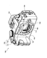
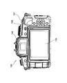
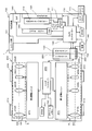
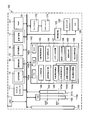
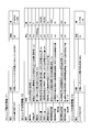
- FIG. 1 A perspective view of the camera body 100 Rear view of camera body 100 Schematic block diagram of digital camera 1 Schematic block diagram of the interchangeable lens unit 200 Schematic block diagram of the camera body 100
- FIG. 1 A) Configuration example of lens identification information F1,
- B Configuration example of lens characteristic information F2
- C Configuration example of lens state information F3
- A Time chart between camera body and interchangeable lens unit (when camera body does not support 3D shooting)
- B Time chart between camera body and interchangeable lens unit (camera body and interchangeable lens unit) Is compatible with 3D photography)
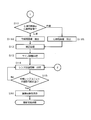
- Explanation of each parameter Explanation of each parameter Flow chart at power ON Flow chart at power ON Flow chart during shooting
- the digital camera 1 is an imaging device capable of three-dimensional imaging, and is a digital camera with interchangeable lenses. As shown in FIGS. 1 to 3, the digital camera 1 includes an interchangeable lens unit 200 and a camera body 100 to which the interchangeable lens unit 200 can be attached.
- the interchangeable lens unit 200 is a lens unit that supports three-dimensional imaging, and forms an optical image of a subject (an optical image for the left eye and an optical image for the right eye).
- the camera body 100 can handle two-dimensional imaging and three-dimensional imaging, and generates image data based on an optical image formed by the interchangeable lens unit 200.
- an interchangeable lens unit that does not support 3D shooting can be attached to the camera body 100. That is, the camera body 100 is compatible with both two-dimensional photography and three-dimensional photography.
- the interchangeable lens unit 200 is a lens unit that supports three-dimensional imaging.
- the interchangeable lens unit 200 of the present embodiment employs a side-by-side imaging method in which two optical images are formed on one image sensor by a pair of left and right optical systems. As shown in FIGS.
- the interchangeable lens unit 200 includes a three-dimensional optical system G, a first drive unit 271, a second drive unit 272, a shake amount detection sensor 275, and a lens controller 240. Further, the interchangeable lens unit 200 includes a lens mount 250, a lens barrel 290, a zoom ring 213, and a focus ring 234. When the interchangeable lens unit 200 is attached to the camera body 100, the lens mount 250 is attached to a body mount 150 (described later) of the camera body 100. As shown in FIG. 1, a zoom ring 213 and a focus ring 234 are rotatably provided outside the lens tube 290.
- the three-dimensional optical system G is an optical system corresponding to the juxtaposed imaging method, and includes a left-eye optical system OL and a right-eye optical system OR.
- the left-eye optical system OL and the right-eye optical system OR are arranged side by side.
- the left-eye optical system is an optical system corresponding to the left viewpoint, and specifically, the optical element arranged closest to the subject (front side) is arranged on the left side toward the subject.
- the right-eye optical system is an optical system corresponding to the right viewpoint, and specifically, the optical element arranged closest to the subject (front side) is arranged on the right side toward the subject.
- the left-eye optical system OL is an optical system for photographing a subject from the left viewpoint toward the subject, and includes a zoom lens 210L, an OIS lens 220L, an aperture unit 260L, and a focus lens 230L.
- the left-eye optical system OL has a first optical axis AX1, and is housed inside the lens barrel 290 in a state of being aligned with the right-eye optical system OR.
- the zoom lens 210L is a lens for changing the focal length of the left-eye optical system OL, and is arranged to be movable in a direction parallel to the first optical axis AX1.
- the zoom lens 210L is composed of one or a plurality of lenses.
- the zoom lens 210L is driven by a zoom motor 214L (described later) of the first drive unit 271.
- the focal length of the left-eye optical system OL can be adjusted by driving the zoom lens 210L in a direction parallel to the first optical axis AX1.
- the OIS lens 220L is a lens for suppressing displacement of an optical image formed by the left-eye optical system OL with respect to the CMOS image sensor 110 (described later).
- the OIS lens 220L is composed of one or a plurality of lenses. Based on the control signal transmitted from the OIS IC 223L, the OIS motor 221L drives the OIS lens 220L so as to move in a plane perpendicular to the first optical axis AX1.
- the OIS motor 221L can be realized by, for example, a magnet (not shown) and a flat coil (not shown).
- the position of the OIS lens 220L is detected by a position detection sensor 222L (described later) of the first drive unit 271.
- an optical method is used as a shake correction method.
- an electronic device that performs correction processing on image data generated by the CMOS image sensor 110, or an image sensor such as the CMOS image sensor 110.
- a sensor shift type that drives the lens in a plane perpendicular to the first optical axis AX1 may be employed as a shake correction method.
- the aperture unit 260L adjusts the amount of light transmitted through the left-eye optical system OL.
- the aperture unit 260L has a plurality of aperture blades (not shown). The aperture blades are driven by an aperture motor 235L (described later) of the first drive unit 271.
- a camera controller 140 controls the aperture motor 235L.
- the focus lens 230L is a lens for adjusting a subject distance (also referred to as an object point distance) of the left-eye optical system OL, and is disposed so as to be movable in a direction parallel to the first optical axis AX1.
- the focus lens 230L is driven by a focus motor 233L (described later) of the first drive unit 271.
- the focus lens 230L is composed of one or a plurality of lenses.
- the right-eye optical system OR is an optical system for photographing the subject from the right viewpoint toward the subject, and includes a zoom lens 210R, an OIS lens 220R, an aperture unit 260R, and a focus lens 230R.
- the right-eye optical system OR has a second optical axis AX2, and is housed inside the lens tube 290 in a state of being side by side with the left-eye optical system OL.
- the specification of the optical system OR for the right eye is the same as the specification of the optical system OL for the left eye. Note that the angle (convergence angle) formed by the first optical axis AX1 and the second optical axis AX2 is an angle ⁇ 1 shown in FIG.
- the zoom lens 210R is a lens for changing the focal length of the right-eye optical system OR, and is arranged to be movable in a direction parallel to the second optical axis AX2.
- the zoom lens 210R is composed of one or a plurality of lenses.
- the zoom lens 210R is driven by a zoom motor 214R (described later) of the second drive unit 272.
- the focal length of the right-eye optical system OR can be adjusted by driving the zoom lens 210R in a direction parallel to the second optical axis AX2.
- the driving of the zoom lens 210R is synchronized with the driving of the zoom lens 210L. Accordingly, the focal length of the right-eye optical system OR is the same as the focal length of the left-eye optical system OL.
- the OIS lens 220R is a lens for suppressing the displacement of the optical image formed by the right-eye optical system OR with respect to the CMOS image sensor 110.
- the OIS lens 220R includes one or a plurality of lenses.
- the OIS motor 221R drives the OIS lens 220R so as to move in a plane perpendicular to the second optical axis AX2.
- the OIS motor 221R can be realized by, for example, a magnet (not shown) and a flat coil (not shown).
- the position of the OIS lens 220R is detected by a position detection sensor 222R (described later) of the second drive unit 272.
- an optical method is used as a shake correction method.
- CMOS image sensor 110 CMOS image sensor 110
- a sensor shift type that drives the imaging element in a plane perpendicular to the second optical axis AX2 may be adopted as a shake correction method.
- the aperture unit 260R adjusts the amount of light that passes through the right-eye optical system OR.
- the aperture unit 260R has a plurality of aperture blades (not shown).
- the aperture blades are driven by an aperture motor 235R (described later) of the second drive unit 272.
- the camera controller 140 controls the aperture motor 235R.
- the driving of the diaphragm unit 260R is synchronized with the driving of the diaphragm unit 260L. Accordingly, the aperture value of the right-eye optical system OR is the same as the aperture value of the left-eye optical system OL.
- the focus lens 230R is a lens for adjusting a subject distance (also referred to as an object point distance) of the right-eye optical system OR, and is disposed so as to be movable in a direction parallel to the second optical axis AX2.
- the focus lens 230R is driven by a focus motor 233R (described later) of the second drive unit 272.
- the focus lens 230R is composed of one or a plurality of lenses.
- the first drive unit 271 is provided to adjust the state of the left-eye optical system OL.
- the zoom motor 214L, the OIS motor 221L, the position detection sensor 222L, the OIS IC 223L, the diaphragm A motor 235L and a focus motor 233L are provided.
- the zoom motor 214L drives the zoom lens 210L.
- the zoom motor 214L is controlled by the lens controller 240.
- the OIS motor 221L drives the OIS lens 220L.
- the position detection sensor 222L is a sensor that detects the position of the OIS lens 220L.
- the position detection sensor 222L is, for example, a Hall element, and is disposed close to the magnet of the OIS motor 221L.
- the OIS IC 223L controls the OIS motor 221L based on the detection result of the position detection sensor 222L and the detection result of the shake amount detection sensor 275.
- the OIS IC 223L acquires the detection result of the shake amount detection sensor 275 from the lens controller 240.
- the OIS IC 223L transmits a signal indicating the position of the OIS lens 220L to the lens controller 240 at a predetermined cycle.
- the aperture motor 235L drives the aperture unit 260L.
- the aperture motor 235L is controlled by the lens controller 240.
- the focus motor 233L drives the focus lens 230L.
- the focus motor 233L is controlled by the lens controller 240.
- the lens controller 240 also controls the focus motor 233R, and synchronizes the focus motor 233L and the focus motor 233R.
- the subject distance of the left-eye optical system OL is the same as the subject distance of the right-eye optical system OR.
- Examples of the focus motor 233L include a DC motor, a stepping motor, a servo motor, and an ultrasonic motor.
- Second drive unit 272 The second drive unit 272 is provided to adjust the state of the right-eye optical system OR. As shown in FIG. 5, the zoom motor 214R, the OIS motor 221R, the position detection sensor 222R, the OIS IC 223R, the diaphragm A motor 235R and a focus motor 233R are provided.
- the zoom motor 214R drives the zoom lens 210R.
- the zoom motor 214R is controlled by the lens controller 240.
- the OIS motor 221R drives the OIS lens 220R.
- the position detection sensor 222R is a sensor that detects the position of the OIS lens 220R.
- the position detection sensor 222R is, for example, a Hall element, and is disposed close to the magnet of the OIS motor 221R.
- the OIS IC 223R controls the OIS motor 221R based on the detection result of the position detection sensor 222R and the detection result of the shake amount detection sensor 275.
- the OIS IC 223R acquires the detection result of the shake amount detection sensor 275 from the lens controller 240.
- the OIS IC 223R transmits a signal indicating the position of the OIS lens 220R to the lens controller 240 at a predetermined cycle.
- the aperture motor 235R drives the aperture unit 260R.
- the aperture motor 235R is controlled by the lens controller 240.
- the focus motor 233R drives the focus lens 230R.
- the focus motor 233R is controlled by the lens controller 240.
- the lens controller 240 synchronizes the focus motor 233L and the focus motor 233R.
- the subject distance of the right-eye optical system OR becomes the same as the subject distance of the left-eye optical system OL.
- Examples of the focus motor 233R include a DC motor, a stepping motor, a servo motor, and an ultrasonic motor.
- Lens controller 240 controls each part (for example, the first drive unit 271 and the second drive unit 272) of the interchangeable lens unit 200 based on the control signal transmitted from the camera controller 140.
- the lens controller 240 performs transmission / reception with the camera controller 140 via the lens mount 250 and the body mount 150.
- the lens controller 240 uses the DRAM 241 as a work memory during control.
- the lens controller 240 has a CPU (Central Processing Unit) 240a, a ROM (Read Only Memory) 240b, and a RAM (Random Access Memory) 240c, and various functions can be achieved by reading a program stored in the ROM 240b into the CPU 240a. Can be realized.
- the flash memory 242 (an example of a correction information storage unit and an example of an identification information storage unit) stores programs and parameters used when the lens controller 240 is controlled. For example, lens identification information F1 (see FIG. 7A) indicating that the interchangeable lens unit 200 supports three-dimensional imaging (see FIG. 7A), lens characteristic information F2 including parameters and flags indicating the characteristics of the three-dimensional optical system G ( 7B) is stored in advance in the flash memory 242. Lens state information F3 (see FIG. 7C) indicating whether or not the interchangeable lens unit 200 is ready for photographing is stored in the RAM 240c, for example.
- F1 see FIG. 7A
- lens characteristic information F2 including parameters and flags indicating the characteristics
- the lens identification information F1 is information indicating whether or not the interchangeable lens unit is compatible with three-dimensional imaging, and is stored in advance in the flash memory 242, for example.
- the lens identification information F1 is a three-dimensional imaging determination flag stored at a predetermined address in the flash memory 242.
- FIGS. 8A and 8B three-dimensional imaging is performed in the initial communication between the camera body and the interchangeable lens unit when the power is turned on or when the interchangeable lens unit is attached to the camera body. The determination flag is transmitted from the interchangeable lens unit to the camera body.
- the lens characteristic information F2 is data indicating the characteristics of the optical system of the interchangeable lens unit, and includes the following parameters and flags as shown in FIG. 7B.
- A Baseline length Baseline length L1 of the stereo optical system
- B Optical axis position Distance L2 from the center C0 (see FIG. 9) of the image sensor (CMOS image sensor 110) to the optical axis center (center ICL of image circle IL or center ICR of image circle IR shown in FIG. 9) Design value)
- C Angle of convergence Angle ⁇ 1 formed by the first optical axis (AX1) and the second optical axis (AX2) (see FIG.
- the optical axis position, the left eye shift amount, and the right eye shift amount are parameters specific to the three-dimensional optical system of the juxtaposition shooting method.
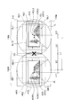
- FIG. 9 is a diagram of the CMOS image sensor 110 viewed from the subject side.
- the CMOS image sensor 110 has a light receiving surface 110 a (see FIGS. 9 and 10) that receives light transmitted through the interchangeable lens unit 200.
- An optical image of the subject is formed on the light receiving surface 110a.
- the light receiving surface 110a includes a first region 110L and a second region 110R disposed adjacent to the first region 110L.
- the area of the first region 110L is the same as the area of the second region 110R.
- FIG. 9 is a diagram of the CMOS image sensor 110 viewed from the subject side.
- the CMOS image sensor 110 has a light receiving surface 110 a (see FIGS. 9 and 10) that receives light transmitted through the interchangeable lens unit 200.
- An optical image of the subject is formed on the light receiving surface 110a.
- the light receiving surface 110a includes a first region 110L and a second region 110R disposed adjacent to the first region 110L.
- the first region 110L occupies the left half of the light receiving surface 110a
- the second region 110R occupies the right half of the light receiving surface 110a.
- the left-eye optical image QL1 is formed in the first region 110L
- the right-eye optical image QR1 is formed in the second region 110R. Is done.
- the designed image circle IL of the optical system OL for the left eye and the image circle IR of the optical system OR for the right eye are defined on the CMOS image sensor 110.
- the center ICL of the image circle IL matches the design position of the first optical axis AX10 of the optical system OL for the left eye
- the center ICR of the image circle IR (an example of the reference extraction position)
- the design position corresponds to the first optical axis AX10 and the second optical axis AX20 when the convergence point is at infinity.
- the design baseline length is the design distance L1 between the first optical axis AX10 and the second optical axis AX20 on the CMOS image sensor 110.
- the optical axis position is a design distance L2 between the center C0 of the light receiving surface 110a and the first optical axis AX10 (or a design distance L2 between the center C0 and the second optical axis AX20).
- the extractable range AL1 and the landscape imaging extractable range AL11 are set based on the center ICL, and the extractable range AR1 and the landscape imaging extractable range AR11 are set based on the center ICR.
- the center ICL is set substantially at the center position of the first region 110L of the light receiving surface 110a
- the extractable ranges AL1 and AL11 in the image circle IL can be secured widely.
- the center ICR is set at a substantially central position of the second region 110R, a wide extractable range AR1 and AR11 in the image circle IR can be secured.
- the extraction areas AL0 and AR0 shown in FIG. 9 are areas that serve as a reference when extracting image data for the left eye and image data for the right eye.
- the design extraction area AL0 for the image data for the left eye is set with the center ICL (or the first optical axis AX10) of the image circle IL as a reference, and is located at the center of the extractable range AL1.
- the design extraction area AR0 of the image data for the right eye is set based on the center ICR (or the second optical axis AX20) of the image circle IR, and is located at the center of the extractable range AR1.
- the optical axis centers ICL and ICR correspond to the case where the convergence point exists at infinity
- the position where the subject is reproduced is an infinite position. Therefore, when the interchangeable lens unit 200 for close-up shooting (for example, when the distance from the shooting position to the main subject is about 1 m) is used in such a setting, the subject can be seen from the screen in the three-dimensional image during stereoscopic viewing. The problem of popping out occurs.
- the extraction area AR0 is set as the recommended extraction area AR3 so that a subject located at a distance of the recommended convergence point distance L10 from the digital camera 1 at the time of shooting is reproduced on the screen during stereoscopic viewing.
- the extraction area AL0 is shifted to the recommended extraction area AR3 by a distance L11.
- the extraction region correction process using the extraction position correction amount L11 will be described later.
- the camera body 100 includes a CMOS image sensor 110, a camera monitor 120, an electronic viewfinder 180, a display control unit 125, an operation unit 130, a card slot 170, a shutter unit 190, a body mount 150, A DRAM 141, an image processing unit 10, and a camera controller 140 (an example of a control unit) are provided. Each of these units is connected to the bus 20, and data can be transmitted / received to / from each other via the bus 20.
- CMOS image sensor 110 The CMOS image sensor 110 converts an optical image of a subject (hereinafter also referred to as a subject image) formed by the interchangeable lens unit 200 into an image signal. As shown in FIG.
- the CMOS image sensor 110 outputs an image signal based on the timing signal generated by the timing generator 112.
- An image signal generated by the CMOS image sensor 110 is digitized by a signal processing unit 15 (described later) and converted into image data.
- Still image data and moving image data can be acquired by the CMOS image sensor 110.
- the acquired moving image data is also used for displaying a through image.
- the through image is an image that is not recorded in the memory card 171 in the moving image data.
- the through image is mainly a moving image, and is displayed on the camera monitor 120 or the electronic viewfinder (hereinafter also referred to as EVF) 180 in order to determine the composition of the moving image or the still image.
- the CMOS image sensor 110 has the light receiving surface 110 a (see FIGS. 6 and 9) that receives the light transmitted through the interchangeable lens unit 200.
- An optical image of the subject is formed on the light receiving surface 110a.
- the first region 110L occupies the left half of the light receiving surface 110a
- the second region 110R occupies the right half of the light receiving surface 110a.
- a left-eye optical image is formed in the first region 110L
- a right-eye optical image is formed in the second region 110R.
- the CMOS image sensor 110 is an example of an image sensor that converts an optical image of a subject into an electrical image signal.
- the imaging element is a concept including a photoelectric conversion element such as a CMOS image sensor 110 or a CCD image sensor.
- the camera monitor 120 is a liquid crystal display, for example, and displays display image data as an image.
- the display image data is image data that has undergone image processing, data for displaying shooting conditions, operation menus, and the like of the digital camera 1 as images, and is generated by the camera controller 140.
- the camera monitor 120 can selectively display both moving images and still images. As shown in FIG. 5, in this embodiment, the camera monitor 120 is disposed on the back surface of the camera body 100, but the camera monitor 120 may be disposed anywhere on the camera body 100.
- the camera monitor 120 is an example of a display unit provided in the camera body 100.
- the display unit other devices that can display an image, such as an organic EL, an inorganic EL, and a plasma display panel, can be used.
- the electronic viewfinder 180 displays the display image data generated by the camera controller 140 as an image.
- the EVF 180 can selectively display both moving images and still images. Further, the EVF 180 and the camera monitor 120 may display the same content or display different content, both of which are controlled by the display control unit 125.
- Operation unit 130 As shown in FIGS. 1 and 2, the operation unit 130 includes a release button 131 and a power switch 132.
- the release button 131 accepts a shutter operation by the user.
- the power switch 132 is a rotary lever switch provided on the upper surface of the camera body 100.
- the operation unit 130 only needs to accept an operation by the user, and includes a button, a lever, a dial, a touch panel, and the like.
- the card slot 170 can be loaded with a memory card 171.
- the card slot 170 controls the memory card 171 based on the control from the camera controller 140.
- the card slot 170 stores image data in the memory card 171 and outputs image data from the memory card 171.
- the card slot 170 stores moving image data in the memory card 171 and outputs moving image data from the memory card 171.
- the memory card 171 can store image data generated by the camera controller 140 through image processing.
- the memory card 171 can store an uncompressed RAW image file, a compressed JPEG image file, and the like.
- the memory card 171 can store a stereo image file in a multi-picture format (MPF) format.
- MPF multi-picture format
- image data stored in advance can be output from the memory card 171 via the card slot 170.
- the image data or image file output from the memory card 171 is subjected to image processing by the camera controller 140.
- the camera controller 140 generates display image data by decompressing image data or an image file acquired from the memory card 171.
- the memory card 171 can further store moving image data generated by the camera controller 140 through image processing.
- the memory card 171 is a video compression standard H.264.
- a moving image file compressed according to H.264 / AVC can be stored.
- a stereo video file can also be stored.
- the moving image data or moving image file stored in advance can be output from the memory card 171 via the card slot 170.
- the moving image data or moving image file output from the memory card 171 is subjected to image processing by the camera controller 140.
- the camera controller 140 performs a decompression process on the moving image data or the moving image file acquired from the memory card 171 to generate display moving image data.
- Shutter unit 190 The shutter unit 190 is a so-called focal plane shutter, and is disposed between the body mount 150 and the CMOS image sensor 110 as shown in FIG.
- the shutter unit 190 is charged by a shutter motor 199.
- the shutter motor 199 is a stepping motor, for example, and is controlled by the camera controller 140.
- Body mount 150 The body mount 150 can be mounted with the interchangeable lens unit 200, and holds the interchangeable lens unit 200 with the interchangeable lens unit 200 mounted.
- the body mount 150 can be mechanically and electrically connected to the lens mount 250 of the interchangeable lens unit 200. Data and / or control signals can be transmitted and received between the camera body 100 and the interchangeable lens unit 200 via the body mount 150 and the lens mount 250. Specifically, the body mount 150 and the lens mount 250 transmit and receive data and / or control signals between the camera controller 140 and the lens controller 240.
- Camera controller 140 controls the entire camera body 100.
- the camera controller 140 is electrically connected to the operation unit 130.
- An operation signal is input from the operation unit 130 to the camera controller 140.
- the camera controller 140 uses the DRAM 141 as a work memory during a control operation or an image processing operation described later. Further, the camera controller 140 transmits a signal for controlling the interchangeable lens unit 200 to the lens controller 240 via the body mount 150 and the lens mount 250 to indirectly control each part of the interchangeable lens unit 200.
- the camera controller 140 receives various signals from the lens controller 240 via the body mount 150 and the lens mount 250.
- the camera controller 140 includes a CPU (Central Processing Unit) 140a, a ROM (Read Only Memory) 140b, and a RAM (Random Access Memory) 140c.
- a program stored in the ROM 140b (a computer-readable recording medium) is stored in the camera controller 140.
- Various functions can be realized by being read by the CPU 140a. (Details of camera controller 140)
- the camera controller 140 detects whether or not the interchangeable lens unit 200 is attached to the camera body 100 (more specifically, the body mount 150).
- the camera controller 140 has a lens detection unit 146.
- the lens detection unit 146 determines whether or not the interchangeable lens unit 200 is attached based on signal transmission / reception.
- the camera controller 140 has a function of determining whether or not the interchangeable lens unit attached to the body mount 150 is compatible with 3D imaging, and a function of acquiring information related to 3D imaging from the interchangeable lens unit. It has various functions.
- the camera controller 140 includes an identification information acquisition unit 142, a characteristic information acquisition unit 143, a camera side determination unit 144, a state information acquisition unit 145, an extraction position correction unit 139, an area determination unit 149, a metadata generation unit 147, and an image file generation unit. 148.
- the identification information acquisition unit 142 acquires lens identification information F ⁇ b> 1 indicating whether or not the interchangeable lens unit 200 is compatible with three-dimensional imaging from the interchangeable lens unit 200 attached to the body mount 150. As shown in FIG.
- the lens identification information F1 is information indicating whether or not the interchangeable lens unit mounted on the body mount 150 is compatible with three-dimensional imaging.
- the lens controller 240 flashes.
- the lens identification information F1 is a three-dimensional imaging determination flag stored at a predetermined address in the flash memory 242.
- the identification information acquisition unit 142 temporarily stores the acquired lens identification information F1 in the DRAM 141, for example.
- the camera side determination unit 144 determines whether or not the interchangeable lens unit 200 attached to the body mount 150 is compatible with three-dimensional imaging. .
- the camera controller 140 allows execution of the 3D shooting mode.
- the camera controller 140 does not execute the 3D shooting mode. In this case, the camera controller 140 allows execution of the two-dimensional imaging mode.
- the characteristic information acquisition unit 143 acquires lens characteristic information F2 indicating the characteristics of the optical system mounted on the interchangeable lens unit 200 from the interchangeable lens unit 200. Specifically, the characteristic information acquisition unit 143 receives the lens characteristic information F2 from the interchangeable lens unit 200 when the camera side determination unit 144 determines that the interchangeable lens unit 200 is compatible with three-dimensional imaging. get. The characteristic information acquisition unit 143 temporarily stores the acquired lens characteristic information F2 in the DRAM 141, for example.
- the state information acquisition unit 145 acquires the lens state information F3 (shooting permission / inhibition flag) generated by the state information generation unit 243. This lens state information F3 is used to determine whether or not the interchangeable lens unit 200 is ready for photographing.
- the state information acquisition unit 145 temporarily stores the acquired lens state information F3 in, for example, the DRAM 141.
- the extraction position correction unit 139 corrects the use extraction area (more specifically, the center position of the use extraction area) used when extracting image data based on the extraction position correction amount L11.
- the use extraction areas are set to the extraction areas AL0 and AR0, the center of the extraction area AL0 is set to the center ICL of the image circle IL, and the center of the extraction area AR0 is set to the center ICR of the image circle IR.
- the extraction position correction unit 139 moves the extraction center in the horizontal direction by the extraction position correction amount L11 from the centers ICL and ICR, and newly extracts the extraction center ACL2 and the reference data for extracting the left-eye image data and the right-eye image data.
- ACR2 an example of a recommended extraction position
- the use extraction areas based on the extraction centers ACL2 and ACR2 are the extraction areas AL2 and AR2 shown in FIG. In this way, by correcting the position of the extraction center using the extraction position correction amount L11, the use extraction area can be set according to the characteristics of the interchangeable lens unit, and a more appropriate stereo image can be obtained. .
- the interchangeable lens unit 200 since the interchangeable lens unit 200 has a zoom function, when the focal length changes due to the zoom operation, the recommended convergence point distance L10 changes, and the extraction position correction amount L11 also changes accordingly. . Therefore, the extraction position correction amount L11 may be recalculated by calculation according to the zoom position.
- the lens controller 240 can grasp the zoom position based on the detection result of the zoom position sensor (not shown). The lens controller 240 transmits zoom position information to the camera controller 140 at a predetermined cycle. Zoom position information is temporarily stored in the DRAM 141.
- the extraction position correction unit 139 calculates an extraction position correction amount suitable for the focal length based on the zoom position information, the recommended convergence point distance L10, and the extraction position correction amount L11, for example.
- information indicating the relationship between the zoom position information, the recommended convergence point distance L10, and the extraction position correction amount L11 may be stored in the camera body 10, or an interchangeable lens. It may be stored in the flash memory 242 of the unit 200.
- the extraction position correction amount is updated at a predetermined cycle.
- the updated extraction position correction amount is stored at a predetermined address in the DRAM 141.
- the extraction position correction unit 139 corrects the center positions of the extraction regions AL0 and AR0 based on the newly calculated extraction position correction amount.
- the region determination unit 149 determines the sizes and positions of the extraction regions AL3 and AR3 used when the image extraction unit 16 extracts the left-eye image data and the right-eye image data. Specifically, the region determination unit 149 includes the extraction centers ACL2 and ACR2 calculated by the extraction position correction unit 139, the radius r of the image circle IL and IR, the left-eye shift amount DL and the right eye included in the lens characteristic information F2. Based on the shift amount DR, the sizes and positions of the extraction regions AL3 and AR3 of the image data for the left eye and the image data for the right eye are determined.
- the region determination unit 149 indicates a 180-degree rotation flag indicating whether or not the left-eye optical image and the right-eye optical image are rotated, and left and right arrangements of the left-eye optical image and the right-eye optical image.
- the left eye image data and the right eye image data can be correctly extracted based on the mirror inversion flag indicating whether the arrangement change flag and the left eye optical image and the right eye optical image are mirror inverted.
- the starting point of the extraction process on the image data may be determined.
- the metadata generation unit 147 generates metadata in which the base line length and the convergence angle are set. The baseline length and the convergence angle are used when displaying a stereo image.
- the image file generation unit 148 generates an MPF format stereo image file by combining the left-eye and right-eye image data compressed by the image compression unit 17 (described later) and the metadata. The generated image file is transmitted to, for example, the card slot 170 and stored in the memory card 171.
- Image processing unit 10 includes a signal processing unit 15, an image extraction unit 16, a correction processing unit 18, and an image compression unit 17.
- the signal processing unit 15 digitizes an image signal generated by the CMOS image sensor 110 and generates basic image data of an optical image formed on the CMOS image sensor 110.
- the signal processing unit 15 converts an image signal output from the CMOS image sensor 110 into a digital signal, and performs digital signal processing such as noise removal and contour enhancement on the digital signal.
- the image data generated by the signal processing unit 15 is temporarily stored in the DRAM 141 as RAW data.
- the image data generated by the signal processing unit 15 is referred to as basic image data.
- the image extraction unit 16 extracts left-eye image data and right-eye image data from the basic image data generated by the signal processing unit 15.
- the left-eye image data corresponds to a part of the left-eye optical image QL1 formed by the left-eye optical system OL.
- the right-eye image data corresponds to a part of the right-eye optical image QR1 formed by the right-eye optical system OR.
- the image extraction unit 16 extracts left-eye image data and right-eye image data from the basic image data stored in the DRAM 141.
- the left-eye image data and right-eye image data extracted by the image extraction unit 16 are temporarily stored in the DRAM 141.
- the correction processing unit 18 performs correction processing such as distortion correction and shading correction on each of the extracted left-eye image data and right-eye image data. After the correction process, the image data for the left eye and the image data for the right eye are temporarily stored in the DRAM 141.
- the image compression unit 17 performs compression processing on the corrected left-eye image data and right-eye image data stored in the DRAM 141 based on a command from the camera controller 140. By this compression processing, the data size of the image data becomes smaller than the original data size.
- a method for compressing image data for example, a JPEG (Joint Photographic Experts Group) method for compressing each frame of image data can be considered.
- the compressed left-eye image data and right-eye image data are temporarily stored in the DRAM 141.
- the lens identification information F1 is acquired from the interchangeable lens unit 200 by the identification information acquisition unit 142 of the camera controller 140 (step S2). Specifically, as shown in FIGS. 8A and 8B, when the lens detection unit 146 of the camera controller 140 detects the mounting of the interchangeable lens unit 200, the camera controller 140 is classified into the lens controller 240. Send confirmation command.
- This type confirmation command is a command that requests the lens controller 240 to transmit the status of the three-dimensional imaging determination flag of the lens identification information F1. As shown in FIG.
- the lens controller 240 since the interchangeable lens unit 200 supports 3D imaging, the lens controller 240 receives the lens identification information F1 (3D imaging determination flag) when receiving the type confirmation command. Send to.
- the identification information acquisition unit 142 temporarily stores the status of the three-dimensional imaging determination flag in the DRAM 141.
- the normal initial communication is communication performed between an interchangeable lens unit that does not support three-dimensional imaging and a camera body.
- information for example, information (focal length, F value, etc.) regarding the specifications of the interchangeable lens unit 200 is the interchangeable lens unit. 200 to the camera body 100.
- the camera side determination unit 144 determines whether or not the interchangeable lens unit 200 attached to the body mount 150 is compatible with three-dimensional imaging (step S4). Specifically, the camera-side determination unit 144 determines that the mounted interchangeable lens unit 200 supports three-dimensional imaging based on the lens identification information F1 (three-dimensional imaging determination flag) acquired by the identification information acquisition unit 142. It is determined whether or not.
- step S8 a normal sequence corresponding to 2D imaging is executed, and the process proceeds to step S14 (step S8).
- the lens characteristic information F2 is acquired from the interchangeable lens unit 200 by the characteristic information acquisition unit 143 (step S5).
- a characteristic information transmission command is transmitted from the characteristic information acquisition unit 143 to the lens controller 240.
- This characteristic information transmission command is a command for requesting transmission of the lens characteristic information F2.
- the camera controller 140 transmits lens characteristic information F2 to the camera controller 140.
- the characteristic information acquisition unit 143 stores the lens characteristic information F2 in the DRAM 141, for example.
- the extraction position correcting unit 139 corrects the positions of the extraction centers AL0 and AR0 (step S6). Specifically, the extraction position correction unit 139 corrects the center positions of the extraction regions AL0 and AR0 based on the extraction position correction amount L11 (or the extraction position correction amount newly calculated from the extraction position correction amount L11). . By moving the extraction center horizontally from the centers ICL and ICR by the extraction position correction amount L11 (or the extraction position correction amount newly calculated from the extraction position correction amount L11), the extraction position correction unit 139 causes the left eye to move. Extraction centers ACL2 and ACR2 are newly set as a reference for extracting image data and right-eye image data.
- the size and position of the extraction regions AL3 and AR3 are determined by the region determination unit 149 based on the lens characteristic information F2 (step S7).
- the extraction area AL3 is based on the optical axis position, the effective imaging area (radius r), the extraction centers ACL2 and ACR2, the left eye deviation DL, the right eye deviation DR, and the size of the CMOS image sensor 110.
- the size of AR3 is determined by the region determination unit 149.
- the size of the extraction areas AL3 and AR3 is determined by the area determination unit 149 based on the above information so that the extraction areas AL3 and AR3 fall within the extractable ranges AL11 and AR11 for landscape photography.
- the region determination unit 149 may determine an extraction method for extracting any image in the extraction regions AL3 and AR3 as the right-eye image, rotating the image, or mirror-inverting the image.
- an image for live view display is selected from the left-eye and right-eye image data (step S10).
- the user may be allowed to select from the left-eye and right-eye image data, or the one determined in advance by the camera controller 140 may be set for display.
- the selected image data is set as a display image and extracted by the image extraction unit 16 (step S11A or 11B).
- correction processing such as distortion correction and shading correction is performed on the extracted image data by the correction processing unit 18 (step S12). Further, the display control unit 125 performs size adjustment processing on the corrected image data to generate image data for display (step S13).
- This correction image data is temporarily stored in the DRAM 141.
- the state information acquisition unit 145 step S14. Specifically, in the interchangeable lens unit 200, when the lens side determination unit 244 receives the above-described characteristic information transmission command, the lens side determination unit 244 determines that the camera body 100 is compatible with three-dimensional imaging (8). (See (B)). On the other hand, the lens-side determination unit 244 determines that the camera body does not support 3D shooting when the characteristic information transmission command is not sent from the camera body during a predetermined period (see FIG. 8A). ).
- the state information generation unit 243 sets the status of a shooting availability flag (an example of standby information) indicating whether or not the shooting state of the three-dimensional optical system G is ready based on the determination result of the lens side determination unit 244. To do.
- the state information generation unit 243 sets the imaging availability flag after completion of initialization of each unit. Set the status to Yes.
- the state information generation unit 243 completes initialization of each unit. Regardless of whether or not it is present, the status of the photographing availability flag is set to “impossible”.
- step S ⁇ b> 14 when a command requesting transmission of the status information of the shooting availability flag is transmitted from the status information acquisition unit 145 to the lens controller 240, the status information generation unit 243 transmits the status information of the shooting availability flag to the camera controller 140. To do.
- the status information of the photographing availability flag is transmitted to the camera controller 140.
- the status information acquisition unit 145 temporarily stores the status information of the photographing availability flag transmitted from the lens controller 240 at a predetermined address of the DRAM 141.
- the state information acquisition unit 145 determines whether or not the interchangeable lens unit 200 is in a photographing enabled state (step S15). When the interchangeable lens unit 200 is not ready for photographing, the processes in steps S14 and S15 are repeated at a predetermined cycle. On the other hand, if the interchangeable lens unit 200 is ready for photographing, the display image data generated in step S13 is displayed as a visible image on the camera monitor 120 (step S16). After Step S16, for example, the left image, the right eye image, the combined image of the left eye image and the right eye image on the camera monitor 120, or the left eye image and the right eye image 3 are used. A three-dimensional image is displayed in live view. (2) Three-dimensional still image shooting Next, the operation at the time of three-dimensional still image shooting will be described with reference to FIG.
- step S21 and S22 When the user presses the release button 131, autofocus (AF) and automatic exposure (AE) are executed, and then exposure is started (steps S21 and S22).
- An image signal (data of all pixels) is taken into the signal processing unit 15 from the CMOS image sensor 110, and signal processing such as AD conversion is performed on the image signal in the signal processing unit 15 (steps S23 and S24).
- the basic image data generated by the signal processing unit 15 is temporarily stored in the DRAM 141.
- the positions of the extraction areas AL3 and AR3 are corrected by the extraction position correction unit 139 according to the focal length (step S25A).
- the extraction position correction unit 139 calculates an extraction position correction amount suitable for the current focal length based on, for example, zoom position information, recommended convergence point distance L10, and extraction position correction amount L11. In this case, as in the case of the extraction position correction amount L11, the center positions of the extraction regions AL0 and AR0 are corrected by the extraction position correction unit 139 based on the newly calculated extraction position correction amount.
- the image extraction unit 16 extracts left-eye image data and right-eye image data from the basic image data (step S25B).
- the values determined in step S7 are used as the sizes of the extraction areas AL3 and AR3 at this time.
- the correction processing unit 18 performs correction processing on the extracted left-eye image data and right-eye image data
- the image compression unit 17 performs compression processing such as JPEG compression on the left-eye image data and the right-eye image data. This is performed on the image data (steps S26 and S27).
- the metadata generation unit 147 of the camera controller 140 generates metadata in which the base line length and the convergence angle are set (step S28).
- the image file generation unit 148 After the metadata is generated, the image file generation unit 148 generates an image file in the MPF format by combining the compressed image data for the left eye and right eye and the metadata (step S29).
- the generated image file is transmitted to, for example, the card slot 170 and stored in the memory card 171.
- this image file is three-dimensionally displayed using the base line length and the convergence angle, the displayed image can be stereoscopically viewed using dedicated glasses or the like.
- the lens identification information is acquired by the identification information acquisition unit 142 from the interchangeable lens unit attached to the body mount 150.
- the identification information acquisition unit 142 acquires the lens identification information F1 indicating whether or not the interchangeable lens unit 200 is compatible with three-dimensional imaging from the interchangeable lens unit 200 attached to the body mount 150.
- the camera-side determination unit determines that the interchangeable lens unit 200 supports three-dimensional imaging based on the lens identification information F1.
- the camera side determination unit 144 determines that the interchangeable lens unit does not support 3D shooting based on the lens identification information F1. To do.
- the camera body 100 can correspond to various interchangeable lens units such as an interchangeable lens unit compatible with three-dimensional imaging and an incompatible lens unit.
- the lens information F2 indicating the characteristics of the interchangeable lens unit is acquired by the characteristics information acquisition unit 143.
- the lens characteristic information F2 indicating the characteristics of the three-dimensional optical system G mounted on the interchangeable lens unit 200 is acquired from the interchangeable lens unit 200 by the characteristic information acquisition unit 143. Therefore, operations such as image processing in the camera body 100 can be adjusted according to the characteristics of the three-dimensional optical system mounted on the interchangeable lens unit.
- the camera side determination unit 144 determines that the interchangeable lens unit mounted on the body mount 150 is compatible with three-dimensional imaging
- the lens characteristic information F2 is obtained from the interchangeable lens unit by the characteristic information acquisition unit 143. To be acquired. Therefore, when the interchangeable lens unit is not compatible with three-dimensional imaging, it is possible to omit the exchange of extra data, and it can be expected that the processing in the camera body 100 is accelerated.
- the extraction position correction unit 139 corrects the center positions of the extraction areas AL0 and AR0 to a position corresponding to the recommended convergence point distance L10 based on the extraction position correction amount L11.
- An extraction region suitable for the characteristics of the interchangeable lens unit can be set. Therefore, the camera body 100 can acquire a more appropriate stereo image.
- the size and position of the left eye image data and right eye image data extraction regions AL3 and AR3 are determined by the region determination unit 149 based on the lens characteristic information F2.
- the extraction areas AL3 and AR3 of the image data for the left eye and the image data for the right eye exceed the effective imaging area of the CMOS image sensor 110 due to the characteristics of the interchangeable lens unit. Can be suppressed.
- the camera body 100 can support various interchangeable lens units such as an interchangeable lens unit compatible with three-dimensional imaging and an incompatible lens unit. .
- the interchangeable lens unit 200 also has the following characteristics. (1) In this interchangeable lens unit 200, since the extraction position correction amount L11 is stored in the flash memory 242, the position of the extraction center can be corrected to a position corresponding to the recommended convergence point distance L10. Therefore, it becomes easier to obtain a more appropriate stereo image. [Other Embodiments]
- the present invention is not limited to the above-described embodiments, and various changes and modifications can be made without departing from the scope of the present invention.
- the imaging apparatus and the camera body have been described by taking the digital camera 1 having no mirror box as an example. However, even a digital single-lens reflex camera having a mirror box can be adapted to three-dimensional imaging. Is possible.
- the imaging device may be a device capable of capturing not only a still image but also a moving image.
- the interchangeable lens unit 200 has been described by taking the interchangeable lens unit 200 as an example, the configuration of the three-dimensional optical system is not limited to the above-described embodiment. The three-dimensional optical system may have other configurations as long as one image sensor can cope with it.
- the three-dimensional optical system G is not limited to the side-by-side photographing method, and for example, a time-division photographing method may be adopted as the optical system of the interchangeable lens unit.
- a time-division photographing method may be adopted as the optical system of the interchangeable lens unit.
- the normal juxtaposed photographing method is described as an example, but the horizontal compression juxtaposed photographing method in which the images for the left eye and the right eye are compressed in the horizontal direction, or for the left eye and the right
- a rotational juxtaposition imaging method in which the ophthalmic image is rotated by 90 degrees may be employed.
- the image size is changed in FIG. 9, when the image sensor is small, the photographing may be prohibited.
- the size of the extraction areas AL3 and AR3 is determined by the area determination unit 149, if the size of the extraction areas AL3 and AR3 is smaller than a predetermined size, a warning display is displayed on the camera monitor 120. You may let them.
- the size of the extraction area can be changed by changing the aspect ratio of the extraction areas AL3 and AR3 (for example, the aspect ratio is 1: 1). Can be changed relatively, the aspect ratio may be changed.
- the extraction area may be reduced without changing the aspect ratio, and the extracted image data may be resized to be enlarged to a predetermined size.
- the interchangeable lens unit 200 described above may be a single focus lens.
- the extraction centers ACL2 and ACR2 can be obtained by using the extraction position correction amount L11 described above.
- the interchangeable lens unit 200 is a single focus lens, for example, the zoom lenses 210L and 210R are fixed, and accordingly, the zoom ring 213 and the zoom motors 214L and 214R may not be mounted.
- the present invention can be applied to a camera body, an interchangeable lens unit, and an imaging device.
Abstract
Description
しかし、視差を有するステレオ画像を生成するためには、3次元撮影用の光学系(以下、3次元光学系とも言う)を用いる必要がある。
そこで、3次元撮影用のアダプタの着脱に基づいて2次元撮影モードと3次元撮影モードとを自動的に切り替えるビデオカメラが提案されている(例えば、特許文献1を参照)。
一方、3次元光学系ごとに適した撮影距離(カメラから輻輳点までの距離)が存在するが、推奨撮影距離が異なると左眼用画像データおよび右眼用画像データの抽出領域の位置が光学系ごとで変化する。
本発明の課題は、より適正なステレオ画像を取得できるカメラ本体および交換レンズユニットを提供することにある。
このカメラ本体では、ボディマウントに装着されている交換レンズユニットから補正情報取得部により抽出位置補正量が取得される。このため、輻輳点距離が無限遠の場合に対応する基準抽出位置から交換レンズユニットの推奨輻輳点距離に対応する推奨抽出位置までのズレ量をカメラ本体が把握することができ、より適切なステレオ画像を取得することができる。
この交換レンズユニットでは、補正情報記憶部が抽出位置補正量を記憶しているので、輻輳点距離が無限遠の場合に対応する基準抽出位置から交換レンズユニットの推奨輻輳点距離に対応する推奨抽出位置までのズレ量をカメラ本体が把握することができ、より適切なステレオ画像を取得することができる。
第3の特徴に係る制御方法は、交換レンズユニットにより形成される光学像に基づいて画像データを生成するカメラ本体の制御方法であって、輻輳点距離が無限遠の場合に対応する基準抽出位置から交換レンズユニットの推奨輻輳点距離に対応する推奨抽出位置までの撮像素子上の距離を示す抽出位置補正量を、ボディマウントに装着されている交換レンズユニットから取得するステップ、を備えている。
第5の特徴に係る記録媒体は、コンピュータにより読み取り可能な記録媒体であって、輻輳点距離が無限遠の場合に対応する基準抽出位置から交換レンズユニットの推奨輻輳点距離に対応する推奨抽出位置までの撮像素子上の距離を示す抽出位置補正量を、交換レンズユニットから取得する補正情報取得機能を、コンピュータに実現させる。
デジタルカメラ1は、3次元撮影が可能な撮像装置であり、レンズ交換式のデジタルカメラである。図1~図3に示すように、デジタルカメラ1は、交換レンズユニット200と、交換レンズユニット200を装着可能なカメラ本体100と、を備えている。交換レンズユニット200は、3次元撮影に対応しているレンズユニットであり、被写体の光学像(左眼用光学像および右眼用光学像)を形成する。カメラ本体100は、2次元撮影および3次元撮影に対応可能であり、交換レンズユニット200により形成される光学像に基づいて画像データを生成する。カメラ本体100には、3次元撮影に対応している交換レンズユニット200の他に、3次元撮影に対応していない交換レンズユニットも取り付けることができる。つまり、カメラ本体100は2次元撮影にも3次元撮影にも対応している。
<1:交換レンズユニットの構成>
交換レンズユニット200は3次元撮影に対応しているレンズユニットである。本実施形態の交換レンズユニット200には、2つの光学像が左右1対の光学系により1つの撮像素子上に形成される並置撮影方式が採用されている。
図1~図4に示すように、交換レンズユニット200は、3次元光学系Gと、第1駆動ユニット271、第2駆動ユニット272、振れ量検出センサー275およびレンズコントローラー240を有している。さらに、交換レンズユニット200は、レンズマウント250、レンズ筒290、ズームリング213およびフォーカスリング234を有している。交換レンズユニット200をカメラ本体100に装着する際、レンズマウント250がカメラ本体100のボディマウント150(後述)に取り付けられる。図1に示すように、レンズ筒290の外部にはズームリング213とフォーカスリング234とが回転可能に設けられている。
図4および図5に示すように、3次元光学系Gは、並置撮影方式に対応した光学系であり、左眼用光学系OLと右眼用光学系ORとを有している。左眼用光学系OLと右眼用光学系ORとは左右に並んで配置されている。ここで、左眼用光学系とは、左側の視点に対応した光学系であり、具体的には、最も被写体側(前側)に配置されている光学素子が被写体に向かって左側に配置されている光学系をいう。同様に、右眼用光学系とは、右側の視点に対応した光学系であり、具体的には、最も被写体側(前側)に配置されている光学素子が被写体に向かって右側に配置されている光学系をいう。
左眼用光学系OLは、被写体に向かって左側の視点から被写体を撮影するための光学系であり、ズームレンズ210L、OISレンズ220L、絞りユニット260Lおよびフォーカスレンズ230Lを含んでいる。左眼用光学系OLは、第1光軸AX1を有しており、右眼用光学系ORと左右に並んだ状態でレンズ筒290の内部に収容されている。
OISレンズ220Lは、左眼用光学系OLで形成される光学像のCMOSイメージセンサー110(後述)に対する変位を抑制するためのレンズである。OISレンズ220Lは1枚または複数枚のレンズで構成される。OISモータ221Lは、OIS用IC223Lから送信される制御信号に基づいて、第1光軸AX1に垂直な面内で移動するようにOISレンズ220Lを駆動する。OISモータ221Lは、例えば、マグネット(図示せず)および平板コイル(図示せず)で実現可能である。OISレンズ220Lの位置は第1駆動ユニット271の位置検出センサー222L(後述)により検出される。
絞りユニット260Lは左眼用光学系OLを透過する光の量を調整する。絞りユニット260Lは複数の絞り羽根(図示せず)を有している。絞り羽根は第1駆動ユニット271の絞りモータ235L(後述)により駆動される。カメラコントローラー140(後述)は絞りモータ235Lを制御する。
フォーカスレンズ230Lは、左眼用光学系OLの被写体距離(物点距離ともいう)を調整するためのレンズであり、第1光軸AX1に平行な方向に移動可能に配置されている。フォーカスレンズ230Lは第1駆動ユニット271のフォーカスモータ233L(後述)により駆動される。フォーカスレンズ230Lは1枚または複数枚のレンズで構成されている。
ズームレンズ210Rは、右眼用光学系ORの焦点距離を変化させるためのレンズであり、第2光軸AX2と平行な方向に移動可能に配置されている。ズームレンズ210Rは1枚または複数枚のレンズで構成されている。ズームレンズ210Rは第2駆動ユニット272のズームモータ214R(後述)により駆動される。ズームレンズ210Rを第2光軸AX2と平行な方向に駆動することにより、右眼用光学系ORの焦点距離を調整することができる。ズームレンズ210Rの駆動はズームレンズ210Lの駆動と同期がとられている。したがって、右眼用光学系ORの焦点距離は左眼用光学系OLの焦点距離と同じである。
なお、本実施形態では、振れ補正の方式として光学式が採用されているが、例えばCMOSイメージセンサー110(後述)で生成される画像データに補正処理を施す電子式、あるいは、CMOSイメージセンサー110などの撮像素子を第2光軸AX2と垂直な面内で駆動するセンサーシフト式が振れ補正の方式として採用されてもよい。
フォーカスレンズ230Rは、右眼用光学系ORの被写体距離(物点距離ともいう)を調整するためのレンズであり、第2光軸AX2に平行な方向に移動可能に配置されている。フォーカスレンズ230Rは第2駆動ユニット272のフォーカスモータ233R(後述)により駆動される。フォーカスレンズ230Rは1枚または複数枚のレンズで構成されている。
第1駆動ユニット271は、左眼用光学系OLの状態を調整するために設けられており、図5に示すように、ズームモータ214L、OISモータ221L、位置検出センサー222L、OIS用IC223L、絞りモータ235Lおよびフォーカスモータ233Lを有している。
ズームモータ214Lはズームレンズ210Lを駆動する。ズームモータ214Lはレンズコントローラー240により制御される。
OISモータ221LはOISレンズ220Lを駆動する。位置検出センサー222LはOISレンズ220Lの位置を検出するセンサーである。位置検出センサー222Lは、例えばホール素子であり、OISモータ221Lのマグネットに近接して配置されている。OIS用IC223Lは、位置検出センサー222Lの検出結果および振れ量検出センサー275の検出結果に基づいて、OISモータ221Lを制御する。OIS用IC223Lはレンズコントローラー240から振れ量検出センサー275の検出結果を取得する。また、OIS用IC223Lはレンズコントローラー240へOISレンズ220Lの位置を示す信号を所定の周期で送信する。
フォーカスモータ233Lはフォーカスレンズ230Lを駆動する。フォーカスモータ233Lはレンズコントローラー240により制御される。レンズコントローラー240は、フォーカスモータ233Rも制御しており、フォーカスモータ233Lおよびフォーカスモータ233Rを同期させる。これにより、左眼用光学系OLの被写体距離が右眼用光学系ORの被写体距離と同じになる。フォーカスモータ233Lとしては、例えばDCモータやステッピングモータ、サーボモータ、超音波モータが考えられる。
(3)第2駆動ユニット272
第2駆動ユニット272は、右眼用光学系ORの状態を調整するために設けられており、図5に示すように、ズームモータ214R、OISモータ221R、位置検出センサー222R、OIS用IC223R、絞りモータ235Rおよびフォーカスモータ233Rを有している。
OISモータ221RはOISレンズ220Rを駆動する。位置検出センサー222RはOISレンズ220Rの位置を検出するセンサーである。位置検出センサー222Rは、例えばホール素子であり、OISモータ221Rのマグネットに近接して配置されている。OIS用IC223Rは、位置検出センサー222Rの検出結果および振れ量検出センサー275の検出結果に基づいて、OISモータ221Rを制御する。OIS用IC223Rはレンズコントローラー240から振れ量検出センサー275の検出結果を取得する。また、OIS用IC223Rはレンズコントローラー240へOISレンズ220Rの位置を示す信号を所定の周期で送信する。
フォーカスモータ233Rはフォーカスレンズ230Rを駆動する。フォーカスモータ233Rはレンズコントローラー240により制御される。レンズコントローラー240はフォーカスモータ233Lおよびフォーカスモータ233Rを同期させる。これにより、右眼用光学系ORの被写体距離が左眼用光学系OLの被写体距離と同じになる。フォーカスモータ233Rとしては、例えばDCモータやステッピングモータ、サーボモータ、超音波モータが考えられる。
(4)レンズコントローラー240
レンズコントローラー240は、カメラコントローラー140から送信される制御信号に基づいて交換レンズユニット200の各部(例えば、第1駆動ユニット271および第2駆動ユニット272)を制御する。レンズコントローラー240はカメラコントローラー140との送受信をレンズマウント250およびボディマウント150を介して行う。レンズコントローラー240は、制御の際、DRAM241をワークメモリとして使用する。
また、フラッシュメモリ242(補正情報記憶部の一例、識別情報記憶部の一例)は、レンズコントローラー240の制御の際に使用するプログラムやパラメータを保存する。例えば、交換レンズユニット200が3次元撮影に対応していることを示すレンズ識別情報F1(図7(A)参照)、3次元光学系Gの特性を示すパラメータおよびフラグを含むレンズ特性情報F2(図7(B)参照)をフラッシュメモリ242は予め記憶している。交換レンズユニット200が撮影可能な状態か否かを示すレンズ状態情報F3(図7(C)参照)は、例えばRAM240cに格納されている。
(レンズ識別情報F1)
レンズ識別情報F1は、交換レンズユニットが3次元撮影に対応しているか否かを示す情報であり、例えばフラッシュメモリ242に予め格納されている。図7(A)に示すように、レンズ識別情報F1は、フラッシュメモリ242内の所定のアドレスに格納された3次元撮影判定フラグである。図8(A)および図8(B)に示すように、カメラ本体および交換レンズユニットの間で、電源ON時または交換レンズユニットがカメラ本体に装着された時に行われる初期通信において、3次元撮影判定フラグは交換レンズユニットからカメラ本体へ送信される。
(レンズ特性情報F2)
レンズ特性情報F2は、交換レンズユニットの光学系の特性を示すデータであり、図7(B)に示すように、以下のパラメータおよびフラグを含んでいる。
(A)基線長
立体光学系(G)の基線長L1
(B)光軸位置
撮像素子(CMOSイメージセンサー110)の中心C0(図9参照)から光軸中心(図9に示すイメージサークルILの中心ICLまたはイメージサークルIRの中心ICR)までの距離L2(設計値)
(C)輻輳角
第1光軸(AX1)および第2光軸(AX2)のなす角度θ1(図10参照)
(D)左眼ズレ量
左眼用光学系(OL)の撮像素子(CMOSイメージセンサー110)上での光軸位置(設計値)に対する左眼用光学像(QL1)のズレ量DL(水平方向:DLx、鉛直方向:DLy)
(E)右眼ズレ量
右眼用光学系(右眼用光学系OR)の撮像素子(CMOSイメージセンサー110)上での光軸位置(設計値)に対する右眼用光学像(右眼用光学像QR1)のズレ量DR(水平方向:DRx、鉛直方向:DRy)
(F)撮像有効エリア
左眼用光学系(OL)および右眼用光学系(OR)のイメージサークル(AL1、AR1)の半径r(図8参照)
(G)推奨輻輳点距離
交換レンズユニット200を用いて3次元撮影を行う際に推奨される、被写体(輻輳点P0)からCMOSイメージセンサー110の受光面110aまでの距離L10(図10参照)
(H)抽出位置補正量
輻輳角θ1がゼロの場合に第1光軸AX1および第2光軸AX2が受光面110aに到達する点(P11およびP12)から、輻輳角θ1が推奨輻輳点距離L10に対応する大きさの場合における第1光軸AX1および第2光軸AX2が受光面110a上に到達する点(P21およびP22)までの距離L11(図10参照)(「輻輳点距離が無限遠の場合に対応する基準抽出位置から交換レンズユニットの推奨輻輳点距離に対応する推奨抽出位置までの撮像素子上の距離」ともいう)
(I)限界輻輳点距離
交換レンズユニット200を用いて3次元撮影を行う際に、左眼用光学像QL1および右眼用光学像QR1の抽出領域がともに撮像有効エリア内に収まる場合の、被写体から受光面110aまでの最短距離L12(図10参照)
(J)抽出位置限界補正量
輻輳角θ1がゼロの場合に第1光軸AX1および第2光軸AX2が受光面110aに到達する点(P11およびP12)から、輻輳角θ1が限界輻輳点距離L12に対応する大きさの場合における第1光軸AX1および第2光軸AX2が受光面110a上に到達する点(P31およびP32)までの距離L13(図10参照)
上記のパラメータのうち、光軸位置、左眼ズレ量および右眼ズレ量は、並置撮影方式の3次元光学系特有のパラメータである。
図9に示す抽出領域AL0およびAR0は、左眼用画像データおよび右眼用画像データを抽出する際の基準となる領域である。左眼用画像データの設計上の抽出領域AL0は、イメージサークルILの中心ICL(あるいは第1光軸AX10)を基準に設定されており、抽出可能範囲AL1の中央に位置している。また、右眼用画像データの設計上の抽出領域AR0は、イメージサークルIRの中心ICR(あるいは第2光軸AX20)を基準に設定されており、抽出可能範囲AR1の中央に位置している。
そこで、撮影時にデジタルカメラ1から推奨輻輳点距離L10だけ離れた位置にある被写体が、立体視の際にスクリーン上に再現されるように、このカメラ本体100では、抽出領域AR0を推奨抽出領域AR3へ、抽出領域AL0を推奨抽出領域AR3へ、それぞれ距離L11だけずらしている。抽出位置補正量L11を用いた抽出領域の補正処理については後述する。
図4および図6に示すように、カメラ本体100は、CMOSイメージセンサー110、カメラモニタ120、電子ビューファインダー180、表示制御部125、操作部130、カードスロット170、シャッターユニット190、ボディマウント150、DRAM141、画像処理部10、カメラコントローラー140(制御部の一例)を備えている。これら各部は、バス20に接続されており、バス20を介して互いにデータの送受信が可能となっている。
(1)CMOSイメージセンサー110
CMOSイメージセンサー110は、交換レンズユニット200により形成される被写体の光学像(以下、被写体像ともいう)を画像信号に変換する。図6に示すように、CMOSイメージセンサー110はタイミングジェネレータ112で生成されるタイミング信号に基づいて画像信号を出力する。CMOSイメージセンサー110で生成された画像信号は、信号処理部15(後述)でデジタル化され画像データに変換される。CMOSイメージセンサー110により静止画データおよび動画データを取得できる。取得された動画データはスルー画像の表示にも用いられる。
前述のように、CMOSイメージセンサー110は、交換レンズユニット200を透過した光を受ける受光面110a(図6および図9参照)を有している。受光面110a上には被写体の光学像が形成される。図9に示すように、カメラ本体100の背面側から見た場合、第1領域110Lは受光面110aの左半分、第2領域110Rは受光面110aの右半分を占めている。交換レンズユニット200を用いて撮影を行う場合は、第1領域110Lには左眼用光学像が形成され、第2領域110Rには右眼用光学像が形成される。
(2)カメラモニタ120
カメラモニタ120は、例えば液晶ディスプレイであり、表示用画像データを画像として表示する。表示用画像データは、画像処理された画像データや、デジタルカメラ1の撮影条件、操作メニュー等を画像として表示するためのデータ等であり、カメラコントローラー140で生成される。カメラモニタ120は、動画も静止画も選択的に表示可能である。図5に示すように、本実施形態では、カメラモニタ120はカメラ本体100の背面に配置されているが、カメラモニタ120はカメラ本体100のどこに配置されていてもよい。
(3)電子ビューファインダー180
電子ビューファインダー180は、カメラコントローラー140で生成された表示用画像データを画像として表示する。EVF180は、動画も静止画も選択的に表示可能である。また、EVF180とカメラモニタ120とは、同じ内容を表示する場合と、異なる内容を表示する場合とがあり、ともに表示制御部125によって制御される。
(4)操作部130
図1および図2に示すように、操作部130は、レリーズ釦131と、電源スイッチ132と、を有している。レリーズ釦131はユーザーによるシャッター操作を受け付ける。電源スイッチ132は、カメラ本体100の上面に設けられた回転式のレバースイッチである。操作部130は、ユーザーによる操作を受け付けることができればよく、ボタン、レバー、ダイアル、タッチパネル等を含む。
カードスロット170は、メモリーカード171を装着可能である。カードスロット170は、カメラコントローラー140からの制御に基づいて、メモリーカード171を制御する。具体的には、カードスロット170は、メモリーカード171に画像データを格納し、メモリーカード171から画像データを出力する。例えば、カードスロット170は、メモリーカード171に動画データを格納し、メモリーカード171から動画データを出力する。
メモリーカード171は、カメラコントローラー140が画像処理により生成した画像データを格納可能である。例えば、メモリーカード171は、非圧縮のRAW画像ファイルや圧縮されたJPEG画像ファイル等を格納できる。さらに、メモリーカード171はマルチピクチャーフォーマット(MPF)形式のステレオ画像ファイルを格納することもできる。
メモリーカード171は、さらに、カメラコントローラー140が画像処理により生成した動画データを格納可能である。例えば、メモリーカード171は、動画圧縮規格であるH.264/AVCに従って圧縮された動画ファイルを格納できる。また、ステレオ動画ファイルを格納することもできる。また、カードスロット170を介して、予め内部に格納された動画データまたは動画ファイルをメモリーカード171から出力できる。メモリーカード171から出力された動画データまたは動画ファイルは、カメラコントローラー140で画像処理される。例えば、カメラコントローラー140は、メモリーカード171から取得した動画データまたは動画ファイルに伸張処理を施し、表示用動画データを生成する。
シャッターユニット190は、いわゆるフォーカルプレーンシャッターであり、図3に示すように、ボディマウント150とCMOSイメージセンサー110との間に配置される。シャッターユニット190のチャージはシャッターモーター199により行われる。シャッターモーター199は、例えばステッピングモータであり、カメラコントローラー140により制御される。
(7)ボディマウント150
ボディマウント150は、交換レンズユニット200を装着可能であり、交換レンズユニット200が装着された状態で交換レンズユニット200を保持する。ボディマウント150は、交換レンズユニット200のレンズマウント250と機械的および電気的に接続可能である。ボディマウント150とレンズマウント250とを介して、カメラ本体100と交換レンズユニット200との間で、データおよび/または制御信号を送受信可能である。具体的には、ボディマウント150とレンズマウント250とは、カメラコントローラー140とレンズコントローラー240との間で、データおよび/または制御信号を送受信する。
カメラコントローラー140はカメラ本体100全体を制御する。カメラコントローラー140は操作部130と電気的に接続されている。カメラコントローラー140には操作部130から操作信号が入力される。カメラコントローラー140は、制御動作や後述の画像処理動作の際に、DRAM141をワークメモリとして使用する。
また、カメラコントローラー140は、交換レンズユニット200を制御するための信号を、ボディマウント150およびレンズマウント250を介してレンズコントローラー240に送信し、交換レンズユニット200の各部を間接的に制御する。また、カメラコントローラー140は、ボディマウント150およびレンズマウント250を介して、レンズコントローラー240から各種信号を受信する。
(カメラコントローラー140の詳細)
ここで、カメラコントローラー140の機能の詳細について説明する。
まず、カメラコントローラー140は、交換レンズユニット200がカメラ本体100(より詳細には、ボディマウント150)に装着されているか否かを検知する。具体的には図6に示すように、カメラコントローラー140はレンズ検知部146を有している。交換レンズユニット200がカメラ本体100に装着されると、カメラコントローラー140とレンズコントローラー240との間で信号の送受信が行われる。レンズ検知部146は、信号の送受信に基づいて交換レンズユニット200が装着されているか否かを判定する。
識別情報取得部142は、交換レンズユニット200が3次元撮影に対応しているか否かを示すレンズ識別情報F1を、ボディマウント150に装着されている交換レンズユニット200から取得する。図7(A)に示すように、レンズ識別情報F1は、ボディマウント150に装着されている交換レンズユニットが3次元撮影に対応しているか否かを示す情報であり、例えばレンズコントローラー240のフラッシュメモリ242に格納されている。レンズ識別情報F1はフラッシュメモリ242の所定のアドレスに格納された3次元撮影判定フラグである。識別情報取得部142は取得したレンズ識別情報F1を例えばDRAM141に一時的に格納する。
特性情報取得部143(補正情報取得部の一例)は、交換レンズユニット200に搭載されている光学系の特性を示すレンズ特性情報F2を交換レンズユニット200から取得する。具体的には、特性情報取得部143は、交換レンズユニット200が3次元撮影に対応しているとカメラ側判定部144により判定された場合に、前述のレンズ特性情報F2を交換レンズユニット200から取得する。特性情報取得部143は、取得したレンズ特性情報F2を例えばDRAM141に一時的に格納する。
抽出位置補正部139は、画像データを抽出する際に用いられる使用抽出領域(より詳細には、使用抽出領域の中心位置)を、抽出位置補正量L11に基づいて補正する。初期状態では、使用抽出領域は抽出領域AL0およびAR0に設定されており、抽出領域AL0の中心はイメージサークルILの中心ICLに設定されており、抽出領域AR0の中心はイメージサークルIRの中心ICRに設定されている。抽出位置補正部139は、中心ICLおよびICRから抽出位置補正量L11だけ抽出中心を水平方向に移動させて、左眼用画像データおよび右眼用画像データを抽出する基準として新たに抽出中心ACL2およびACR2(推奨抽出位置の一例)を設定する。抽出中心ACL2およびACR2を基準とした使用抽出領域は、図9に示す抽出領域AL2およびAR2となる。このように、抽出位置補正量L11を用いて抽出中心の位置を補正することで、交換レンズユニットの特性に応じて使用抽出領域を設定することができ、より適正なステレオ画像を得ることができる。
具体的には、レンズコントローラー240はズーム位置センサ(図示せず)の検出結果に基づいてズームポジションを把握できる。レンズコントローラー240はズームポジション情報をカメラコントローラー140に所定の周期で送信する。ズームポジション情報はDRAM141に一時的に格納される。
一方、抽出位置補正部139は、例えば、ズームポジション情報、推奨輻輳点距離L10および抽出位置補正量L11に基づいて焦点距離に適した抽出位置補正量を算出する。このとき、例えば、ズームポジション情報、推奨輻輳点距離L10および抽出位置補正量L11の関係を示す情報(例えば、演算式やデータテーブルなど)がカメラ本体10に格納されていてもよいし、交換レンズユニット200のフラッシュメモリ242に格納されていてもよい。抽出位置補正量の更新は所定の周期で行われる。更新された抽出位置補正量はDRAM141の所定のアドレスに格納される。この場合、抽出位置補正部139は、抽出位置補正量L11の場合と同様に、新たに算出された抽出位置補正量に基づいて抽出領域AL0およびAR0の中心位置を補正する。
なお、領域決定部149が、左眼用光学像および右眼用光学像が回転しているか否かを示す180度回転フラグ、左眼用光学像および右眼用光学像の左右の配置を示す配置変更フラグおよび左眼用光学像および右眼用光学像がそれぞれミラー反転しているか否かを示すミラー反転フラグに基づいて、左眼用画像データおよび右眼用画像データを正しく抽出できるように、画像データ上における抽出処理の始点を決定してもよい。
画像ファイル生成部148は、画像圧縮部17(後述)により圧縮された左眼用および右眼用画像データとメタデータとを組み合わせて、MPF形式のステレオ画像ファイルを生成する。生成された画像ファイルは、例えばカードスロット170に送信されメモリーカード171に保存される。
(9)画像処理部10
画像処理部10は、信号処理部15、画像抽出部16、補正処理部18および画像圧縮部17を有している。
信号処理部15は、CMOSイメージセンサー110で生成される画像信号をデジタル化してCMOSイメージセンサー110上に結像する光学像の基本画像データを生成する。具体的には、信号処理部15は、CMOSイメージセンサー110から出力される画像信号をデジタル信号に変換し、そのデジタル信号に対してノイズ除去や輪郭強調等のデジタル信号処理を施す。信号処理部15により生成された画像データはRAWデータとしてDRAM141に一時的に記憶される。ここでは、信号処理部15により生成された画像データを基本画像データと呼ぶ。
補正処理部18は、抽出した左眼用画像データおよび右眼用画像データのそれぞれに対して歪曲収差補正およびシェーディング補正などの補正処理を行う。補正処理後、左眼用画像データおよび右眼用画像データはDRAM141に一時的に格納される。
〔デジタルカメラの動作〕
(1)電源ON時
交換レンズユニット200が3次元撮影に対応しているか否かの判定は、カメラ本体100の電源がONの状態で交換レンズユニット200がカメラ本体100に装着されたとき、あるいは、交換レンズユニット200がカメラ本体100に装着された状態でカメラ本体100の電源がONになったとき、が考えられる。ここでは、後者の場合を例にデジタルカメラ1の動作を図8(A)、図8(B)、図11および図12のフローを用いて説明する。もちろん、前者の場合にも、同様の動作を行ってもよい。
通常初期通信の後、カメラ側判定部144により、ボディマウント150に装着されている交換レンズユニット200が3次元撮影に対応しているか否かが判定される(ステップS4)。具体的には、カメラ側判定部144は、識別情報取得部142により取得されたレンズ識別情報F1(3次元撮影判定フラグ)に基づいて、装着されている交換レンズユニット200が3次元撮影に対応しているか否かが判定される。
さらに、レンズ特性情報F2に基づいて領域決定部149により抽出領域AL3およびAR3のサイズおよび位置が決定される(ステップS7)。例えば、前述のように、光軸位置、撮像有効エリア(半径r)、抽出中心ACL2およびACR2、左眼ズレ量DL、右眼ズレ量DRおよびCMOSイメージセンサー110のサイズに基づいて、抽出領域AL3およびAR3のサイズが領域決定部149により決定される。例えば、抽出領域AL3およびAR3が横長撮影用抽出可能範囲AL11およびAR11内に収まるように、上記の情報に基づいて、抽出領域AL3およびAR3のサイズが領域決定部149により決定される。
また、抽出領域AL3およびAR3のいずれの画像を右眼用画像として抽出するか、画像を回転するか、画像をミラー反転するかといった抽出方法が領域決定部149により決定されてもよい。
さらに、ライブビュー表示用の画像が左眼用および右眼用画像データから選択される(ステップS10)。例えば、左眼用および右眼用画像データからユーザーに選択させるようにしてもよいし、また、カメラコントローラー140において予め決定されている方を表示用として設定してもよい。選択された方の画像データが表示用画像として設定され、画像抽出部16により抽出される(ステップS11Aまたは11B)。
その後、交換レンズユニットが撮影可能状態にあるか否かが状態情報取得部145により確認される(ステップS14)。具体的には、交換レンズユニット200では、前述の特性情報送信コマンドをレンズ側判定部244が受信すると、レンズ側判定部244はカメラ本体100が3次元撮影に対応していると判定する(8(B)参照)。一方、レンズ側判定部244は、特性情報送信コマンドが所定期間の間にカメラ本体から送られてこない場合に、カメラ本体が3次元撮影に対応していないと判定する(図8(A)参照)。
(2)3次元静止画撮影
次に、図13を用いて3次元静止画撮影時の動作について説明する。
信号処理の後、抽出領域AL3およびAR3の位置は焦点距離に応じて抽出位置補正部139により補正される(ステップS25A)。具体的には、抽出位置補正部139により、例えば、ズームポジション情報、推奨輻輳点距離L10および抽出位置補正量L11に基づいて現在の焦点距離に適した抽出位置補正量が算出される。この場合、抽出位置補正量L11の場合と同様に、新たに算出された抽出位置補正量に基づいて、抽出位置補正部139により抽出領域AL0およびAR0の中心位置が補正される。
さらに、補正処理部18により、抽出された左眼用画像データおよび右眼用画像データに補正処理が施され、画像圧縮部17によりJPEG圧縮などの圧縮処理が左眼用画像データおよび右眼用画像データに対して行われる(ステップS26およびS27)。
圧縮処理後、カメラコントローラー140のメタデータ生成部147により、基線長および輻輳角を設定したメタデータが生成される(ステップS28)。
メタデータ生成後、圧縮された左眼用および右眼用画像データとメタデータとを組み合わせて、MPF形式の画像ファイルが画像ファイル生成部148により生成される(ステップS29)。生成された画像ファイルは、例えばカードスロット170に送信されメモリーカード171に保存される。この画像ファイルを基線長および輻輳角を用いて3次元表示すると、専用メガネなどを用いれば表示された画像を立体視することができる。
以上に説明したカメラ本体の特徴を以下にまとめる。
(1)カメラ本体100では、ボディマウント150に装着されている交換レンズユニットから識別情報取得部142によりレンズ識別情報が取得される。例えば、交換レンズユニット200が3次元撮影に対応しているか否かを示すレンズ識別情報F1が、ボディマウント150に装着されている交換レンズユニット200から識別情報取得部142により取得される。このため、3次元撮影に対応している交換レンズユニット200がカメラ本体100に装着されると、レンズ識別情報F1に基づいて交換レンズユニット200が3次元撮影に対応しているとカメラ側判定部144が判断する。逆に、3次元撮影に対応していない交換レンズユニットがカメラ本体100装着されると、レンズ識別情報F1に基づいて交換レンズユニットが3次元撮影に対応していないとカメラ側判定部144が判断する。
(2)また、カメラ本体100では、交換レンズユニットの特性(例えば光学系の特性)を示すレンズ特性情報F2が特性情報取得部143により取得される。例えば、交換レンズユニット200に搭載されている3次元光学系Gの特性を示すレンズ特性情報F2が交換レンズユニット200から特性情報取得部143により取得される。したがって、交換レンズユニットに搭載されている3次元光学系の特性に応じて、カメラ本体100における画像処理などの動作を調整することができる。
また、ボディマウント150に装着されている交換レンズユニットが3次元撮影に対応しているとカメラ側判定部144により判定された場合に、レンズ特性情報F2が交換レンズユニットから特性情報取得部143により取得される。したがって、交換レンズユニットが3次元撮影に対応していない場合に、余分なデータのやりとりを省略することができ、カメラ本体100での処理の高速化が期待できる。
(4)さらに、このカメラ本体100では、レンズ特性情報F2に基づいて領域決定部149により左眼用画像データおよび右眼用画像データの抽出領域AL3およびAR3のサイズおよび位置が決定される。したがって、抽出位置補正部139により抽出中心を補正しても、交換レンズユニットの特性により左眼用画像データおよび右眼用画像データの抽出領域AL3およびAR3がCMOSイメージセンサー110の撮像有効エリアを越えてしまうのを抑制できる。
〔交換レンズユニットの特徴〕
また、交換レンズユニット200も以下のような特徴を有している。
(1)この交換レンズユニット200では、抽出位置補正量L11がフラッシュメモリ242に記憶されているので、推奨輻輳点距離L10に対応する位置に抽出中心の位置を補正することができる。したがって、より適正なステレオ画像を得やすくなる。
〔他の実施形態〕
本発明は、前述の実施形態に限定されるものではなく、本発明の範囲を逸脱することなく種々の変形および修正が可能である。
(B)交換レンズユニット200を例に、交換レンズユニットについて説明しているが、3次元光学系の構成は前述の実施形態に限定されない。1つの撮像素子で対応できるのであれば、3次元光学系が他の構成を有していてもよい。
(C)3次元光学系Gは並置撮影方式に限定されず、例えば交換レンズユニットの光学系として時分割撮影方式が採用されていてもよい。また、前述の実施形態では、通常の並置撮影方式を例に記載しているが、水平方向に左眼用および右眼用画像が圧縮される水平圧縮並置撮影方式、あるいは、左眼用および右眼用画像を90度回転させた回転並置撮影方式が採用されていてもよい。
また、画像データを抽出する際にアスペクト比を変更せずに抽出領域を縮小し、抽出された画像データが所定のサイズまで拡大するようリサイズしてもよい。
(E)前述の交換レンズユニット200は、単焦点レンズであってもよい。この場合、前述の抽出位置補正量L11を用いることで、抽出中心ACL2およびACR2を求めることができる。なお、交換レンズユニット200が単焦点レンズの場合は、例えば、ズームレンズ210Lおよび210Rが固定されており、それに伴い、ズームリング213、ズームモータ214Lおよび214Rが搭載されていなくてもよい。
15 信号処理部
16 画像抽出部
17 画像圧縮部
18 補正処理部
100カメラ本体
110 CMOSイメージセンサー(撮像素子の一例)
139 抽出位置補正部
140 カメラコントローラー
140a CPU
140b ROM(角度記憶部の一例)
140c RAM
141 DRAM
142 識別情報取得部
143 特性情報取得部(補正情報取得部の一例)
144 カメラ側判定部
145 状態情報取得部
146 レンズ検知部
147 メタデータ生成部
148 画像ファイル生成部
149 領域決定部
150 ボディマウント
200 交換レンズユニット
240 レンズコントローラー
240a CPU
240b ROM
240c RAM
241 DRAM
242 フラッシュメモリ(補正情報記憶部の一例)
243 状態情報生成部
244 レンズ側判定部
OL 左眼用光学系
OR 右眼用光学系
QL1 左眼用光学像
QR1 右眼用光学像
F1 レンズ識別情報
F2 レンズ特性情報
F3 レンズ状態情報
300 交換レンズユニット
400 アダプタ
500 コリメータレンズ
510 測定用カメラ本体
520 測定用交換レンズユニット
550 チャート
600 交換レンズユニット
Claims (20)
- 交換レンズユニットにより形成される光学像に基づいて画像データを生成するカメラ本体であって、
前記交換レンズユニットを装着可能に設けられたボディマウントと、
前記光学像を画像信号に変換する撮像素子と、
輻輳点距離が無限遠の場合に対応する基準抽出位置から前記交換レンズユニットの推奨輻輳点距離に対応する推奨抽出位置までの前記撮像素子上の距離を示す抽出位置補正量を、前記ボディマウントに装着されている前記交換レンズユニットから取得可能な補正情報取得部と、
を備えたカメラ本体。 - 前記抽出位置補正量に基づいて、画像データを抽出する際に用いられる使用抽出領域を、前記基準抽出位置から前記推奨抽出位置に補正する抽出位置補正部をさらに備えた、
請求項1に記載のカメラ本体。 - 前記交換レンズユニットが3次元撮影に対応しているか否かを示すレンズ識別情報を、前記ボディマウントに装着されている前記交換レンズユニットから取得可能な識別情報取得部と、
前記レンズ識別情報に基づいて、前記ボディマウントに装着されている前記交換レンズユニットが3次元撮影に対応しているか否かを判定するカメラ側判定部と、をさらに備え、
前記補正情報取得部は、前記交換レンズユニットが3次元撮影に対応していると前記カメラ側判定部により判定された場合に、前記抽出位置補正量を前記交換レンズユニットから取得する、
請求項1または2に記載のカメラ本体。 - 前記撮像素子で生成される画像信号をデジタル化して前記撮像素子上に結像する光学像の基本画像データを生成する信号処理部と、
前記基本画像データの一部を抽出するための領域であって、前記左眼用光学像の少なくとも一部に対応する左眼用画像データを抽出するための第1抽出領域と、前記右眼用光学像の少なくとも一部に対応する右眼用画像データを抽出するための第2抽出領域と、を決定する領域決定部と、をさらに備えた、
請求項1から3のいずれかに記載のカメラ本体。 - 前記領域決定部は、前記推奨抽出位置に基づいて前記第1および第2抽出領域を決定する、
請求項4に記載のカメラ本体。 - 撮像素子を有するカメラ本体に装着可能な交換レンズユニットであって、
被写体の立体視用光学像を形成する3次元光学系と、
輻輳点距離が無限遠の場合に対応する基準抽出位置から前記交換レンズユニットの推奨輻輳点距離に対応する推奨抽出位置までの前記撮像素子上の距離を示す抽出位置補正量を記憶する補正情報記憶部と、
を備えた交換レンズユニット。 - 前記補正情報記憶部は、前記推奨輻輳点距離を記憶する、
請求項6に記載のレンズユニット。 - 請求項1から5のいずれかに記載のカメラ本体と、
請求項6または7に記載の交換レンズユニットと、
を備えた撮像装置。 - 交換レンズユニットにより形成される光学像に基づいて画像データを生成するカメラ本体の制御方法であって、
輻輳点距離が無限遠の場合に対応する基準抽出位置から前記交換レンズユニットの推奨輻輳点距離に対応する推奨抽出位置までの前記撮像素子上の距離を示す抽出位置補正量を、ボディマウントに装着されている前記交換レンズユニットから取得するステップ、
を備えた制御方法。 - 前記抽出位置補正量に基づいて、前記基準抽出位置を前記推奨抽出位置に補正するステップをさらに備えた、
請求項9に記載の制御方法。 - 前記交換レンズユニットが3次元撮影に対応しているか否かを示すレンズ識別情報を、前記ボディマウントに装着されている前記交換レンズユニットから取得するステップと、
前記レンズ識別情報に基づいて、前記ボディマウントに装着されている前記交換レンズユニットが3次元撮影に対応しているか否かを判定するステップと、をさらに備え、
前記ボディマウントに装着されている前記交換レンズユニットが3次元撮影に対応しているか否かを判定するステップにおいて、前記交換レンズユニットが3次元撮影に対応していると前記カメラ側判定部により判定された場合に、前記抽出位置補正量を前記交換レンズユニットから取得する、
請求項9または10に記載の制御方法。 - 前記撮像素子で生成される画像信号をデジタル化して前記撮像素子上に結像する光学像の基本画像データを生成するステップと、
前記基本画像データの一部を抽出するための領域であって、前記左眼用光学像の少なくとも一部に対応する左眼用画像データを抽出するための第1抽出領域と、前記右眼用光学像の少なくとも一部に対応する右眼用画像データを抽出するための第2抽出領域と、を決定するステップと、をさらに備えた、
請求項9から11のいずれかに記載の制御方法。 - 輻輳点距離が無限遠の場合に対応する基準抽出位置から交換レンズユニットの推奨輻輳点距離に対応する推奨抽出位置までの前記撮像素子上の距離を示す抽出位置補正量を、前記交換レンズユニットから取得する補正情報取得機能
をコンピュータに実現させるプログラム。 - 前記抽出位置補正量に基づいて、前記基準抽出位置を前記推奨抽出位置に補正する抽出位置補正機能をコンピュータに実現させる、
請求項13に記載のプログラム。 - 前記交換レンズユニットが3次元撮影に対応しているか否かを示すレンズ識別情報を、前記ボディマウントに装着されている前記交換レンズユニットから取得可能な識別情報取得機能と、
前記レンズ識別情報に基づいて、前記ボディマウントに装着されている前記交換レンズユニットが3次元撮影に対応しているか否かを判定するカメラ側判定機能と、をコンピュータに実現させ、
前記補正情報取得部は、前記交換レンズユニットが3次元撮影に対応していると前記カメラ側判定部により判定された場合に、前記抽出位置補正量を前記交換レンズユニットから取得する、
請求項13または14に記載のプログラム。 - 前記撮像素子で生成される画像信号をデジタル化して前記撮像素子上に結像する光学像の基本画像データを生成する信号処理機能と、
前記基本画像データの一部を抽出するための領域であって、前記左眼用光学像の少なくとも一部に対応する左眼用画像データを抽出するための第1抽出領域と、前記右眼用光学像の少なくとも一部に対応する右眼用画像データを抽出するための第2抽出領域と、を決定する領域決定機能と、をコンピュータに実現させる、
請求項13から15のいずれかに記載のプログラム。 - 輻輳点距離が無限遠の場合に対応する基準抽出位置から交換レンズユニットの推奨輻輳点距離に対応する推奨抽出位置までの前記撮像素子上の距離を示す抽出位置補正量を、前記交換レンズユニットから取得する補正情報取得機能を、コンピュータに実現させるプログラムを記録した、
コンピュータにより読み取り可能な記録媒体。 - 前記抽出位置補正量に基づいて、前記基準抽出位置を前記推奨抽出位置に補正する抽出位置補正機能を、コンピュータに実現させるプログラムを記録した、
請求項17に記載の記録媒体。 - 前記交換レンズユニットが3次元撮影に対応しているか否かを示すレンズ識別情報を、前記ボディマウントに装着されている前記交換レンズユニットから取得可能な識別情報取得機能と、
前記レンズ識別情報に基づいて、前記ボディマウントに装着されている前記交換レンズユニットが3次元撮影に対応しているか否かを判定するカメラ側判定機能と、をコンピュータに実現させるプログラムを記録し、
前記補正情報取得機能は、前記交換レンズユニットが3次元撮影に対応していると前記カメラ側判定部により判定された場合に、前記抽出位置補正量を前記交換レンズユニットから取得可能とする、
請求項17または18に記載の記録媒体。 - 前記撮像素子で生成される画像信号をデジタル化して前記撮像素子上に結像する光学像の基本画像データを生成する信号処理機能と、
前記基本画像データの一部を抽出するための領域であって、前記左眼用光学像の少なくとも一部に対応する左眼用画像データを抽出するための第1抽出領域と、前記右眼用光学像の少なくとも一部に対応する右眼用画像データを抽出するための第2抽出領域と、を決定する領域決定機能と、をコンピュータに実現させるプログラムを記録した、
請求項17から19のいずれかに記載の記録媒体。
Priority Applications (2)
| Application Number | Priority Date | Filing Date | Title |
|---|---|---|---|
| US13/702,621 US20130088580A1 (en) | 2010-07-27 | 2011-02-08 | Camera body, interchangeable lens unit, image capturing device, method for controlling camera body, program, and recording medium on which program is recorded |
| JP2012526272A JPWO2012014347A1 (ja) | 2010-07-27 | 2011-02-08 | 交換レンズユニット、カメラ本体、撮像装置、カメラ本体の制御方法、プログラムおよびプログラムを記録した記録媒体 |
Applications Claiming Priority (2)
| Application Number | Priority Date | Filing Date | Title |
|---|---|---|---|
| JP2010168352 | 2010-07-27 | ||
| JP2010-168352 | 2010-07-27 |
Publications (1)
| Publication Number | Publication Date |
|---|---|
| WO2012014347A1 true WO2012014347A1 (ja) | 2012-02-02 |
Family
ID=45529585
Family Applications (1)
| Application Number | Title | Priority Date | Filing Date |
|---|---|---|---|
| PCT/JP2011/000693 WO2012014347A1 (ja) | 2010-07-27 | 2011-02-08 | カメラ本体、交換レンズユニット、撮像装置、カメラ本体の制御方法、プログラムおよびプログラムを記録した記録媒体 |
Country Status (3)
| Country | Link |
|---|---|
| US (1) | US20130088580A1 (ja) |
| JP (1) | JPWO2012014347A1 (ja) |
| WO (1) | WO2012014347A1 (ja) |
Families Citing this family (4)
| Publication number | Priority date | Publication date | Assignee | Title |
|---|---|---|---|---|
| JP2014107669A (ja) * | 2012-11-27 | 2014-06-09 | Canon Inc | 立体撮影レンズシステムおよびそれを有する撮影システム |
| JP2018036415A (ja) * | 2016-08-30 | 2018-03-08 | オリンパス株式会社 | カメラシステム、交換レンズ、カメラシステムの制御方法、及びカメラシステムの制御プログラム |
| JP1613801S (ja) * | 2017-12-27 | 2018-09-18 | ||
| CN112188187B (zh) * | 2019-07-01 | 2024-01-02 | 北京小米移动软件有限公司 | 一种图像采集组件的位置检测方法、装置及存储介质 |
Citations (6)
| Publication number | Priority date | Publication date | Assignee | Title |
|---|---|---|---|---|
| JPH0884353A (ja) * | 1994-09-12 | 1996-03-26 | Victor Co Of Japan Ltd | 立体画像撮像装置 |
| JPH08149515A (ja) * | 1994-11-18 | 1996-06-07 | Sanyo Electric Co Ltd | 立体撮像装置 |
| JPH08205200A (ja) * | 1995-01-27 | 1996-08-09 | Olympus Optical Co Ltd | 立体撮像装置 |
| JP2003134534A (ja) * | 2001-10-25 | 2003-05-09 | Olympus Optical Co Ltd | 撮像装置 |
| JP2004153808A (ja) * | 2002-10-10 | 2004-05-27 | Fuji Photo Optical Co Ltd | 立体電子映像装置 |
| JP2005062729A (ja) * | 2003-08-20 | 2005-03-10 | Olympus Corp | カメラ |
Family Cites Families (2)
| Publication number | Priority date | Publication date | Assignee | Title |
|---|---|---|---|---|
| JPH0795623A (ja) * | 1993-06-25 | 1995-04-07 | Sanyo Electric Co Ltd | 立体撮像装置 |
| JP2002077945A (ja) * | 2000-06-07 | 2002-03-15 | Canon Inc | 録画装置、撮像装置、撮像システム、信号処理方法、記録制御方法及び記憶媒体 |
-
2011
- 2011-02-08 WO PCT/JP2011/000693 patent/WO2012014347A1/ja active Application Filing
- 2011-02-08 US US13/702,621 patent/US20130088580A1/en not_active Abandoned
- 2011-02-08 JP JP2012526272A patent/JPWO2012014347A1/ja active Pending
Patent Citations (6)
| Publication number | Priority date | Publication date | Assignee | Title |
|---|---|---|---|---|
| JPH0884353A (ja) * | 1994-09-12 | 1996-03-26 | Victor Co Of Japan Ltd | 立体画像撮像装置 |
| JPH08149515A (ja) * | 1994-11-18 | 1996-06-07 | Sanyo Electric Co Ltd | 立体撮像装置 |
| JPH08205200A (ja) * | 1995-01-27 | 1996-08-09 | Olympus Optical Co Ltd | 立体撮像装置 |
| JP2003134534A (ja) * | 2001-10-25 | 2003-05-09 | Olympus Optical Co Ltd | 撮像装置 |
| JP2004153808A (ja) * | 2002-10-10 | 2004-05-27 | Fuji Photo Optical Co Ltd | 立体電子映像装置 |
| JP2005062729A (ja) * | 2003-08-20 | 2005-03-10 | Olympus Corp | カメラ |
Also Published As
| Publication number | Publication date |
|---|---|
| US20130088580A1 (en) | 2013-04-11 |
| JPWO2012014347A1 (ja) | 2013-09-09 |
Similar Documents
| Publication | Publication Date | Title |
|---|---|---|
| WO2011142086A1 (ja) | カメラ本体、交換レンズユニット、撮像装置、カメラ本体の制御方法、交換レンズユニットの制御方法、プログラムおよびプログラムを記録した記録媒体 | |
| JP5789793B2 (ja) | 3次元撮像装置、レンズ制御装置、およびプログラム | |
| JP2012075078A (ja) | カメラ本体、撮像装置、カメラ本体の制御方法、プログラムおよびプログラムを記録した記録媒体 | |
| JP2012085258A (ja) | カメラ本体、撮像装置、カメラ本体の制御方法、プログラムおよびプログラムを記録した記録媒体 | |
| JP5938659B2 (ja) | 撮像装置およびプログラム | |
| JP4763827B2 (ja) | 立体画像表示装置、複眼撮像装置及び立体画像表示プログラム | |
| JP2011259168A (ja) | 立体パノラマ画像撮影装置 | |
| JP2012186612A (ja) | 撮像装置 | |
| JP2012239135A (ja) | 電子機器 | |
| WO2012014347A1 (ja) | カメラ本体、交換レンズユニット、撮像装置、カメラ本体の制御方法、プログラムおよびプログラムを記録した記録媒体 | |
| JP2012085252A (ja) | 画像生成装置、画像生成方法、プログラムおよびプログラムを記録した記録媒体 | |
| JP2015019118A (ja) | 撮像装置、撮像システムおよび撮像装置の制御プログラム | |
| US20130076867A1 (en) | Imaging apparatus | |
| JP4217182B2 (ja) | 撮影装置 | |
| JP2012004949A (ja) | カメラ本体、交換レンズユニットおよび撮像装置 | |
| JP2012239134A (ja) | 電子機器 | |
| JP2011091750A (ja) | 立体画像撮像装置及びその制御方法 | |
| JP2014155126A (ja) | 表示装置、表示方法およびプログラム | |
| JP2012237937A (ja) | 電子機器 | |
| JP2011135374A (ja) | 3次元デジタルカメラ | |
| JP2013097376A (ja) | カメラモジュール及びその画像補正方法 | |
| JP2013115467A (ja) | 立体撮影装置およびそれを用いた携帯端末装置 | |
| JP2012237936A (ja) | 電子機器 | |
| JP2015028548A (ja) | 撮像装置 | |
| JP2010109709A (ja) | 撮像ユニットおよび電子機器および動画撮影表示システム |
Legal Events
| Date | Code | Title | Description |
|---|---|---|---|
| 121 | Ep: the epo has been informed by wipo that ep was designated in this application |
Ref document number: 11811954 Country of ref document: EP Kind code of ref document: A1 |
|
| WWE | Wipo information: entry into national phase |
Ref document number: 2012526272 Country of ref document: JP |
|
| WWE | Wipo information: entry into national phase |
Ref document number: 13702621 Country of ref document: US |
|
| NENP | Non-entry into the national phase |
Ref country code: DE |
|
| 122 | Ep: pct application non-entry in european phase |
Ref document number: 11811954 Country of ref document: EP Kind code of ref document: A1 |