WO2012014261A1 - 電子機器及びその製造方法 - Google Patents
電子機器及びその製造方法 Download PDFInfo
- Publication number
- WO2012014261A1 WO2012014261A1 PCT/JP2010/004850 JP2010004850W WO2012014261A1 WO 2012014261 A1 WO2012014261 A1 WO 2012014261A1 JP 2010004850 W JP2010004850 W JP 2010004850W WO 2012014261 A1 WO2012014261 A1 WO 2012014261A1
- Authority
- WO
- WIPO (PCT)
- Prior art keywords
- unit
- display
- function
- inclined surface
- light
- Prior art date
Links
Images


Classifications
-
- G—PHYSICS
- G06—COMPUTING; CALCULATING OR COUNTING
- G06F—ELECTRIC DIGITAL DATA PROCESSING
- G06F1/00—Details not covered by groups G06F3/00 - G06F13/00 and G06F21/00
- G06F1/16—Constructional details or arrangements
- G06F1/1613—Constructional details or arrangements for portable computers
- G06F1/1615—Constructional details or arrangements for portable computers with several enclosures having relative motions, each enclosure supporting at least one I/O or computing function
- G06F1/1616—Constructional details or arrangements for portable computers with several enclosures having relative motions, each enclosure supporting at least one I/O or computing function with folding flat displays, e.g. laptop computers or notebooks having a clamshell configuration, with body parts pivoting to an open position around an axis parallel to the plane they define in closed position
-
- G—PHYSICS
- G06—COMPUTING; CALCULATING OR COUNTING
- G06F—ELECTRIC DIGITAL DATA PROCESSING
- G06F1/00—Details not covered by groups G06F3/00 - G06F13/00 and G06F21/00
- G06F1/16—Constructional details or arrangements
- G06F1/1613—Constructional details or arrangements for portable computers
- G06F1/1633—Constructional details or arrangements of portable computers not specific to the type of enclosures covered by groups G06F1/1615 - G06F1/1626
- G06F1/1684—Constructional details or arrangements related to integrated I/O peripherals not covered by groups G06F1/1635 - G06F1/1675
- G06F1/1688—Constructional details or arrangements related to integrated I/O peripherals not covered by groups G06F1/1635 - G06F1/1675 the I/O peripheral being integrated loudspeakers
Definitions
- the present invention relates to a casing technology of an electronic device in which a first casing portion and a second casing portion are joined so as to be openable and closable.
- an electronic device that mounts a new function using the joint portion and It relates to the manufacturing method.
- the operation-side housing unit includes a plurality of operation buttons, a display, and various types such as a speaker function unit and a photographing function unit.
- Functions are arranged and configured. There are some that display characters, icons, and the like indicating the assigned functions in the vicinity of those function units. Some of them emit light in order to increase the visibility of operation buttons, displays, etc., or to improve the design.
- a light guide plate is installed behind a switch button formed of a transparent resin and a light guide member that guides light from a light source is disposed as a light source for an operation unit or the like (for example, Patent Document 1). ). Further, it is known that an operation button is formed of a light guide member, and light from a light emitting means is guided to the operation button (for example, Patent Document 2).
- the operation buttons and cameras mounted in this way need to clearly indicate to the user what function the button corresponds to, and whether the function is operating or stopped.
- the operation button has a function name and icon display corresponding to the vicinity of the operation button, but as described above, the arrangement space is limited, and even if means such as emitting the display is used, It may be difficult for a PC user to see.
- Patent Documents 1 and 2 do not disclose or suggest them, and do not disclose or suggest a configuration to solve them.
- an object of the electronic device and the manufacturing method thereof of the present disclosure is to effectively use the housing space part to enable various functions to be mounted and to improve the visibility of the display unit with respect to operation buttons and the like.
- an electronic device includes a first housing portion, a second housing portion, a hinge portion, and an inclined surface portion.
- the hinge portion connects the first housing portion and the second housing portion so as to be openable and closable.
- the inclined surface portion is configured on the hinge portion side of the first housing portion, and has at least one of a display function, an audio output function, a light emission output function, or a photographing function inside.
- the manufacturing method of the electronic device of this indication includes the process of comprising a connection process, the process of comprising an inclined surface part, and the function part.
- the connecting step the first casing portion and the second casing portion are connected to each other by a hinge portion so as to be opened and closed.
- the step of forming the inclined surface portion the inclined surface portion is formed on the hinge portion side of the first housing portion.
- the step of configuring the functional unit configures at least one functional unit among the display functional unit, the audio output functional unit, the light emission output functional unit, or the photographing functional unit inside the inclined surface unit.
- FIG. 7 is a sectional view taken along the line VII-VII in FIG.
- FIG. 6 is a sectional view taken along the line VIII-VIII in FIG.
- FIG. 12 is a sectional view taken along the line XV-XV in FIG. 11.
- FIG. 12 is a cross-sectional view taken along the line XVI -XVI in FIG. 11.
- FIG. 18 is a cross-sectional view taken along line XVIII-XVIII in FIG.
- FIG. 18 is a cross-sectional view taken along the line XIX-XIX in FIG.
- FIG. 1 is a diagram illustrating a configuration example of an electronic device according to the first embodiment
- FIG. 2 is a diagram illustrating a configuration example of the electronic device in a closed state.
- the configuration illustrated in FIGS. 1 and 2 is an example, and is not limited thereto.
- the electronic device 2 is an example of the electronic device of the present disclosure, and includes a first housing unit 4 and a second housing unit 6 that are connected to be openable and closable. Further, the first housing part 4 constitutes an inclined surface part 8 in which a part of the housing on the connection side with the second housing part 6 is inclined.
- the inclined surface portion 8 includes a hinge portion 10 that joins the first housing portion 4 and the second housing portion 6, and a functional portion 12 that provides a predetermined function in the electronic device 2. ing.
- the first housing part 4 includes, for example, a lower surface part installed on a desk and an upper surface part which is a flat surface facing the lower surface part.
- the first housing 4 is an example of an operation-side housing having an input operation function or the like of the electronic device 2, and a plane such as a keyboard, cursor keys, or a touch pad is provided on the upper surface of the first housing 4. Input operation means are provided.
- the second housing unit 6 is an example of a display-side housing unit having a display function of the electronic device 2, and includes, for example, a display unit.
- the inclined surface portion 8 is an example of a housing portion configured by inclining a part of the first housing portion 4.
- the inclined surface portion 8 includes a hinge portion 10 inside and a functional portion 12 of the electronic device 2. ing.
- the inclined surface portion 8 is a surface that is adjacent to the plane that is the upper surface of the first casing portion 4 and that is continuous with the end of the plane. Further, the inclined surface portion 8 may constitute an inclined portion by using, for example, a hinge cover provided in the first housing portion 4. And outside the inclined surface part 8, the display function part etc. which were comprised toward the user side of the electronic device 2 are provided. Accordingly, the inclined surface portion 8 constitutes, for example, a third housing portion of the electronic device 2.
- the function unit 12 is an example of a functional configuration of the electronic device 2 disposed inside the inclined surface unit 8.
- a display function unit that displays an operation state of the electronic device 2, an audio output function unit configured by a speaker, and the like. It has. Moreover, you may provide the light emission output function part using LED etc., and imaging
- FIG. 2 shows a case where the first housing 4 and the second housing 6 are closed.
- the inner surface of the housing portion 6 is in contact with the housing portion 4, and part or all of the inclined surface portion 8 is directed outward from the hinge portion side of the second housing portion 6. Will be exposed.
- the function unit 12 includes a display function unit and a voice output function unit
- the electronic device 2 can be closed while the electronic device 2 is in operation, and the operation state can be displayed on the display function unit.
- audio output may be performed from a speaker or the like in the closed state.
- the space part comprised inside the hinge part of an electronic device can be used effectively, and size reduction of an electronic device can be achieved.
- the arrangement space for the functional configuration can be increased without degrading the assemblability of the electronic device.
- FIG. 3 is a diagram illustrating a functional configuration example of the electronic device according to the second embodiment
- FIG. 4 is a flowchart illustrating an example of functional processing of the electronic device.
- the configurations, processing contents, processing procedures, and the like shown in FIGS. 3 and 4 are examples, and the present invention is not limited to these.
- the first housing unit 4 includes a first functional unit 14 that operates the electronic device 2, controls input operations, performs power supply control, and the like.
- the inclined surface portion 8 includes, as an example of the function unit 12, a second function unit 16 such as a display function.
- the second functional unit 16 may be configured to function in conjunction with the first functional unit 14, for example.
- the interlocking of the function units 14 and 16 displays, for example, an operation state that is the second function unit 16 of the inclined surface unit 8 by an input operation on the first function unit 14.
- step S2 of the second function unit 16 is performed in accordance with the execution process (step S1) of the first function unit 14, as shown in FIG. What is necessary is just to comprise.
- This execution function interlocking process is an example of an operation control program for the second functional unit 16 of the electronic device 2.
- the second function unit 16 is linked to the first function unit 14, for example, when the operation button or the display unit is caused to emit light for the input operation function of the operation button, it is common in the inclined surface unit 8. You may implement
- FIG. 5 is a diagram illustrating an example of an external configuration of a PC according to the third embodiment
- FIG. 6 is a diagram illustrating an example of a state where the display-side housing unit and the operation-side housing unit are separated
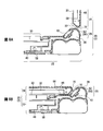
- FIG. 5 is a sectional view taken along the line VII-VII in FIG. 5
- FIG. 8 is a sectional view taken along the line VIII-VIII in FIG.
- the configurations shown in FIGS. 5 to 8 are examples, and the present invention is not limited to these.
- the PC (Personal Computer) 20 is an example of the electronic device 2 according to the present disclosure, and an inclined surface portion 28 is formed in a part of the operation-side housing portion 22, and functions such as a display function are provided inside the inclined surface portion 28. Department. As shown in FIG. 5, the PC 20 connects the operation-side casing 22 and the display-side casing 24 with a hinge 26 so as to be opened and closed.
- the inclined surface portion 28 of the operation-side housing portion 22 is formed at a connection portion with the display-side housing portion 24 and incorporates a hinge portion 26.
- the operation-side housing unit 22 is an example of the first housing unit 4 described above, and includes, for example, a keyboard 33 and a touch pad 34 on an upper surface thereof as operation input means. Further, on the hinge portion 26 side of the plane portion, a power function of the PC 20, an operation button 36 to which a shortcut key for starting an application such as the Internet or mail is assigned, and a display function for displaying the operating state of the PC 20 or during operation processing, etc. Part 38 and the like. Operation input means such as the keyboard 33, the touch pad 34, and the operation buttons 36, the display function unit 38, and the like are examples of the first function unit 14 described above.
- the operation-side housing unit 22 is configured by joining an upper housing cover 56 and a lower housing cover 58 and having an ODD device 40 and the like for reading and writing the above-described functional units and recording media. Yes.
- the display-side casing unit 24 is an example of the second casing unit 6 described above, and includes a display unit 30 configured by, for example, an LCD (Liquid Crystal Display). Further, as shown in FIG. 6, the display-side casing portion 24 corresponds to the shape of the inclined surface portion 28 so that the inclined surface portion 28 of the operation-side casing portion 22 is exposed in the opened state of the PC 20. A concave inclined window portion 32 is formed.
- the inclined surface portion 28 is an example of the inclined surface portion 8 described above, and includes, for example, a speaker 42 and a camera 44 as a built-in functional portion.
- the inclined surface portion 28 is adjacent to the flat surface portion of the operation-side housing portion 22 and is a surface continuous to the end of the flat surface portion.
- a display function unit 46 that displays the operation state of the operation button 36 by light emission is provided.
- the inclined surface portion 28 incorporates the hinge portion 26, and includes, for example, hinge holes 52 and 54 for accommodating the hinge pins 48 and 50 formed in the display-side housing portion 24 on the side surface side.
- the operation-side housing unit 22 includes a control board 60 that constitutes a control unit that causes the PC 20 to function inside the keyboard 33.
- the inclined surface portion 28 joins the hinge cover 62 to the lower housing cover 58 of the operation-side housing portion 22 and houses the hinge pins 48 and 50 therein or incorporates the above-described various functional portions. It constitutes the space.
- the hinge cover 62 is installed up to a part of the flat surface portion of the operation-side housing portion 22, for example, the installation portion of the keyboard 33, and is joined to the upper housing cover 56.
- the operation button 36 described above is installed on the flat surface of the hinge cover 62.
- a control board 64 that is connected to the operation buttons 36, the display function unit 38, and the like and performs operation control and the like is provided inside the hinge cover 62.
- the hinge cover 62 may be formed integrally with the upper housing cover 56.
- the display-side housing unit 24 joins an external housing cover 66 and an internal housing cover 68 to sandwich the display unit 30 and the like inside.
- an inclined window portion 32 formed at an angle that does not buffer the inclined surface portion 28 in the opened / closed state of the display-side housing portion 24 is formed.
- the inclined window portion 32 is close to the inclined surface portion 28 without a gap when the display-side housing portion 24 is closed to the operation-side housing portion 22, and prevents foreign matter from entering from the outside.
- an inclined window portion 70 configured to face the inclined window portion 32 is formed on the outer housing cover 66 side.
- FIG. 1 An example of the internal configuration of this PC 20 is shown in FIG. 1
- the operation side housing unit 22 includes an ODD device 40 therein.
- the inclined surface portion 28 incorporates an audio output function portion, and the speaker 42 is inclined and installed on the inclined surface constituted by the hinge cover 62.
- the inclined surface of the inclined surface portion 28 is opened by the inclined window portion 32, and the speaker 42 is exposed toward the user side of the PC 20.
- the display-side casing 24 When the display-side casing 24 is in a closed state, the keyboard 33 and the like of the operation-side casing 22 are covered as shown in FIG. 8B.
- the display-side housing unit 24 is disposed at a position that contacts or covers a part of the hinge cover 62 of the operation-side housing unit 22, and the inclined window unit 32 is one of the speakers 42 of the inclined surface unit 28. It will be in the state which covers a part.
- a portion of the speaker 42 on the inclined surface portion 28 is exposed toward the outside of the PC 20 by the inclined window portion 70 formed on the outer housing cover 66 of the display-side housing portion 24.
- FIG. 9 is an assembly diagram illustrating a configuration example of the operation-side casing of the electronic device.
- the configuration shown in FIG. 9 is an example, and the present invention is not limited to this.
- the operation side casing 22 of the PC 20 is configured by stacking, for example, a keyboard 33, an upper casing cover 56, a control board 60, a lower casing cover 58, and the like.
- the keyboard 33 is an example of an input operation unit, and a character input can be performed by transmitting a detection signal of an operation input by pressing to the control board 60 side through the connector cable 72.
- the upper housing cover 56 includes a hinge cover 62 that constitutes an inclined surface portion 28 in which a part of the hinge portion 26 side is inclined. Hinge holes 52 and 52 for receiving the hinge pins 48 and 50 (FIG. 6) are formed on both side surfaces of the hinge cover 62.
- the upper housing cover 56 includes a touch pad 34 that is an example of an input operation unit, and performs operations such as a cursor displayed on the display unit 30. Further, the upper housing cover 56 is provided with, for example, a metal reinforcing plate 74, and a part of the reinforcing plate 74 is used as a placement portion on which the keyboard 33 is placed. The reinforcing plate 74 is fixed inside the upper housing cover 56 and protects the control board 60 and the like built in the PC 20.
- a display unit 76 Inside the inclined surface portion 28, for example, a display unit 76, a speaker 42, a camera 44, and a control board 64 that display the state of the operation buttons 36 arranged in the plane portion of the hinge cover 62 are provided.
- the display unit 76 is an example of the display function unit 46 of the operation button 36, and one or more display units 76 are installed according to the number of operation buttons 36 arranged.
- the operation buttons 36 and the display unit 76 are made of, for example, a light guide member, and can be illuminated using a common light emitting element.
- the camera 44 is disposed on the inclined surface portion 28, and is an example of a photographing unit that captures an image on the user side of the PC 20, for example.
- the camera 44 can capture an image in conjunction with the keyboard 33, the touch pad 34, the operation button 36, and the like.
- the camera 44 can be used when an image of a user is attached to an email.
- the control board 64 is connected to the operation button 36, the display unit 76 disposed on the inclined surface part 28, the camera 44, the speaker 42, and the like, and is connected to the control board 60 that controls the entire functions of the PC 20 with a connector cable 80. Yes. Then, operation control of these functional units, power supply control, and the like are performed.
- the control board 64 includes one or a plurality of LEDs (Light Emitting Diodes) 82 as light emitting elements. The number of the LEDs 82 to be installed may be determined according to the number of the operation buttons 36 and the light emitting display unit 90, for example.
- the control board 60 is an example of a control unit of the PC 20, and is configured by, for example, a mother board.
- the ODD device 40 using a magnetic medium, the HDD as a storage unit, the touch pad 34, the connector cables 72, 80, and the like. Connect etc.
- a CPU, a RAM and the like for controlling the PC 20 are mounted.
- the lower housing cover 58 includes a plurality of holding portions 84 that hold the control board 60 in a predetermined position.
- a window 86 for mounting the ODD device 40 and the like is provided on the side surface of the lower housing cover 58.
- the lower housing cover 58 may be made of a resin material, for example.
- the lower housing cover 58 includes hinge holes 52 and 54 constituting the hinge portion 26.
- FIG. 10 is a partial cross-sectional view showing an internal configuration example of the inclined surface portion
- FIG. 11 is a diagram showing an internal configuration example of the inclined surface portion
- FIG. 12 is an arrangement configuration example of the operation buttons and the light guide portion with respect to the upper housing cover.
- FIGS. 13 and 14 are diagrams showing examples of the operation button and the light guide unit
- FIG. 15 is a cross-sectional view taken along line XV-XV in FIG. 11
- FIG. 16 is a cross-sectional view taken along line XVI--XVI in FIG.
- the configurations shown in FIGS. 10 to 16 are examples, and the present invention is not limited to these.
- the upper casing cover 56 has an operation button 36 and a light emitting display portion 90 arranged at predetermined positions on a flat portion on the inclined surface portion 28 side, and is exposed to the user side.
- the operation buttons 36 and the light emitting display unit 90 are placed in correspondence with the LEDs 82 of the control board 64 installed inside the upper housing cover 56.
- the operation button 36 and the light emission display part 90 are provided with the light guide part 92 formed along the inclined hinge cover 62, for example.
- the light guide unit 92 is an example of a unit that guides light emitted from the LEDs 82 installed on the control board 64 to the display unit 76 side to emit light.
- the operation button 36 or the light emitting display unit 90 installed on the plane unit is provided. Is formed.
- an icon display unit 94 that indicates the function assigned to the operation button 36 is provided on the surface of the hinge cover 62. Then, the display unit 76 is turned on or blinked with respect to the display of the icon display unit 94, for example, in conjunction with the pressing of the operation button 36, the operating state and operating state of the assigned functional unit The display function is demonstrated.
- locking pins 100 for fixing the operation buttons 36 and the light emitting display portion 90 at predetermined positions.
- a plurality of the locking pins 100 may be provided for each of the operation buttons 36 and the light emitting display units 90 that are arranged.
- the operation button 36 and the light emission display part 90 side are provided with the latch hole 102 which penetrates the latch pin 100.
- the upper housing cover 56 includes a standing wall portion 104 for preventing light emitted from the operation buttons 36 and the light emitting display section 90 from interfering with the adjacent operation buttons 36 and the like.
- a standing wall portion 104 for preventing light emitted from the operation buttons 36 and the light emitting display section 90 from interfering with the adjacent operation buttons 36 and the like.
- the standing wall 104 may be installed for each operation button 36 or the light emitting display 90 installed.
- Each operation button 36 is provided with a protrusion 106 on the back side, and when the operation button 36 is pressed, it contacts a switch portion on the control board 64 (not shown) to activate the assigned function.
- the light guide unit 92 is disposed along the inclined surface of the inclined surface unit 28 from the operation button 36 side toward the display unit 76 side.
- the inclined surface portion 28 is provided with a plurality of standing wall portions 110 for preventing the light guide from interfering between the light guide portions 92 arranged.
- the hinge cover 62 includes an operation button window 112 that exposes the operation button 36 on the front side of the upper housing cover 56 and a display window 114 that exposes the light emitting display 90 on the flat surface side. I have.
- the hinge cover 62 includes a display window 116 for exposing the display unit 76 on the inclined surface.
- the hinge cover 62 is provided with a window portion on the inclined surface side where, for example, the speaker 42 and the camera 44 are disposed and exposed to the user side.
- the operation button 36 and the light emitting display unit 90 may be configured to be connected by a connecting unit 118 according to the arrangement configuration of the hinge cover 62 to be installed, for example, as shown in FIGS. 13 and 14.
- the connecting portion 118, the operation button 36, and the light emitting display portion 90 may be formed of, for example, the same member, and the operation button 36 and the light emitting display portion 90 are formed by forming a locking hole 102 in each part of the connecting portion 118. It is possible to improve the installation fixing property and the assembling property.
- the connecting portion 118 is connected to a connecting portion 120 that connects the light guide portion 92.
- the connecting portion 120 may be formed integrally with the light guide portion 92, for example.
- the operation button 36, the light emission display part 90, the light guide part 92, the display part 76, and the connection parts 118 and 120 are comprised by the member which has light propagation functions, such as a polycarbonate and ABS resin, as the same member. And you may shape
- the light guide unit disposed at the opposite position together with the operation button 36 and the light emitting display unit 90 by the light emission of the LED 82 disposed in the vicinity of each operation button 36 and the light emitting display unit 90.
- the light is guided at 92 to cause each display unit 76 to emit light.
- a nearby LED 82 emits light
- the corresponding display unit 76 emits light in conjunction with the operation button 36. Therefore, the operation of the assigned function and the operation of the assigned function are performed. Can be notified.
- the LED 82 of the control board 64 is installed between the operation button 36 and the light guide portion 92 disposed on the hinge cover 62 side.
- the protrusion 106 inside the operation button 36 contacts the switch 122 of the control board 64 and causes the LED 82 to emit light.
- the light emitted from the LED 82 is guided to the operation button 36 side constituted by a light guide member and guided to the display unit 76 side by the light guide unit 92.
- the operation button 36 and the display unit 76 work together to illuminate this light.
- the icon display part 94 is installed for every display part 76 in the inclined surface part 28, for example.
- the icon display unit 94 displays the function assigned to the operation button 36 on the display unit 76 that illuminates in conjunction with the pressing operation of the operation button 36.
- a plurality of LEDs 82 are mounted on the control board 64 on the light emitting display unit 90 side.
- the LED 82A is caused to emit light
- the LED 82B is caused to emit light.
- the light emission display unit 90 or the light emission of the display unit 76 may be controlled to be switched in conjunction with an operation of the keyboard 33 or the like, an open / close state of the PC 20, or the like.
- FIGS. 17, 18, and 19 for the fourth embodiment.
- 17 is a diagram showing an example of the external configuration of the PC according to the fourth embodiment
- FIG. 18 is a cross-sectional view taken along the line XVIII--XVIII in FIG. 17
- FIG. 19 is a cross-sectional view taken along the line XIX--XIX in FIG. is there.
- the configurations shown in FIGS. 17 to 19 are examples, and the present invention is not limited to these. Explanation of the same parts as those shown in FIGS. 7 and 8 is omitted.
- the PC 20 is an example of the electronic device 2 according to the present disclosure, and as illustrated in FIG. 17, the display-side casing unit 24 connected by the hinge unit 26 is tilted toward the operation-side casing unit 22 so as to be closed. It shows the case.
- a part or all of the inclined surface portion 28 is exposed from the inclined window portion 70 formed in the display-side housing portion 24 toward the exterior side of the PC 20.
- the inclined surface portion 28 is exposed toward the inner side of the PC 20 from the inclined window portion 32 formed inside the display-side housing portion 24.
- the inclined window portion 70 is formed opposite to the inclined window portion 32 (FIG. 6) in the display-side housing portion 24, and the display-side housing portion 24 is placed on the inclined surface portion 28 in the opening / closing operation of the PC 20. By passing, the inclined windows 32 and 70 to be exposed are switched.
- the PC 20 in the closed state maintains an operating state, and can use, for example, a sound output function using the speaker 42 and a photographing function by the camera 44. Further, the operating state of each PC 20 and its functional units can be notified by the lighting and flashing display of the display unit 76 exposed from the inclined window unit 70. As described above, when the PC 20 is in the closed state, for example, the display unit 30 of the PC 20 may not be used, or the display-side housing unit 24 of the PC 20 may be folded and compactly carried. In this case, for example, the function of the inclined surface portion 28 may be operated in conjunction with an operation portion provided on a side surface or the like of the casing portion (not shown).
- the display unit 76 in the closed state is exposed from the inclined window unit 70 to the outside of the PC 20 together with the icon display unit 94.
- the inclined window portion 70 is formed, for example, in the vertical direction with respect to the inclined surface portion 28, and the display portion 76 and the icon display portion 94 can be viewed from a predetermined direction outside the display-side housing portion 24. .
- the camera 44 installed on the inclined surface portion 28 is provided with a lens, a finder, and the like toward the inclined window portion 70, and images are taken from the inclined window portion 70 in the closed PC 20. It can be performed. In this case, photographing by the camera 44 may be performed according to an operation on an operation button (not shown) installed in the operation-side housing unit 22 or the display-side housing unit 24, for example.
- the operation button 36 is arranged on a horizontal portion in the vicinity of the display unit 30 of the information processing apparatus such as the PC 20. Between the operation button 36 and the display unit 30, an inclined surface portion 28 configured on the main body side (operation side housing portion 22) is provided facing the user, and a character / icon display is installed on the inclined surface portion 28.
- the horizontal operation button 36 is illuminated from the inside of the information processing apparatus (PC 20) with the LED 82 or the like, and the character / icon is set in the range where the light can reach on the inclined surface portion 28.
- the operation button 36 is composed of a light guide component, its shape is extended from the inside of the information processing device (PC 20) to the inclined surface portion 28, guides light to the inside of the inclined surface portion, and characters / icons are displayed on the inclined surface portion 28. Light from the back side.
- an icon display or the like adjacent to the operation button 36 is arranged on the inclined surface portion 28, The visibility to the side is improved.
- the icon linked to the operation button 36 is displayed on the display side, or the icon blinks.
- the display unit 30 can be enlarged by arranging the state display function and the like arranged around the display-side casing unit 24 on the inclined surface unit 28.
- FIG. 20 is a diagram illustrating a functional configuration example of an electronic device according to the fifth embodiment.
- the configuration illustrated in FIG. 20 is an example, and the present invention is not limited to this.
- the PC 20 has, for example, a display function, an audio output function, a light emission output function, a photographing function, and other functions.
- a control unit for these functions a processor 150, a storage unit 152, a RAM (Random Access Memory). 158 etc.
- the processor 150 inputs and outputs control information to and from the input unit 160, the open / close detection unit 162, the power supply unit 164, the camera 44, the speaker 42, the display unit 166, and the like.
- the processor 150 is an example of computing means for computing and executing an OS (Operating System) stored in the storage unit 152 and other control programs, and constitutes a control unit of the PC 20.
- the processor 150 may be configured by, for example, a CPU (Central ⁇ ⁇ ⁇ Processing Unit). Then, by executing the calculation of the control program, for example, in response to pressing of the operation button 36, light emission control of the display unit 76 mounted on the inclined surface portion 28, photographing control, display control, audio output control, and the like are performed.
- the storage unit 152 is an example of a storage unit or a recording unit, and stores an OS that controls the operation of the PC 20, other control programs, other information, and the like.
- the storage unit 152 includes, for example, a program storage unit 154, a data storage unit 156, and the like.
- the program storage unit 154 is an example of a unit that stores an OS of the PC 20, a control program such as a light emission control program, and the like, and includes, for example, a ROM (Read Only Memory).
- the data storage unit 156 is an example of a unit that stores image information acquired by photographing, and is configured by, for example, a ROM or a flash memory.
- program storage unit 154 and the data storage unit 156 may be configured by, for example, an EEPROM (Electrically-Erasable-and Programmable-Read-Only-Memory) that can be electrically rewritten.
- EEPROM Electrically-Erasable-and Programmable-Read-Only-Memory
- control programs such as light emission control, display control, photographing control, and audio output control are not limited to those stored in the program storage unit 154, the data storage unit 156, and the like.
- a computer-readable recording medium such as a magnetic disk, flexible disk, optical disk, or magneto-optical disk may be used.
- a program or the like may be read from a server or database on the network and used.
- the RAM 158 constitutes a work area for executing the above control program and the like. Then, the control program is executed by the processor 150, and the first function unit 14 and the second function unit 16 described above may be operated in conjunction with each other. Further, for example, the light emission control may be performed on the display unit 76 of the inclined surface unit 28 in conjunction with the pressing of the operation button 36 or the open / close state of the display-side housing unit 24.
- the input unit 160 is an example of means for detecting an input operation on the PC 20 and notifying the processor 150 of the detection result, and includes, for example, a keyboard 33 and operation buttons 36.
- the light emission control of the LED 82 is performed to cause the display unit 76 and the like installed on the inclined surface unit 28 to emit light.
- the open / close detection unit 162 is an example of means for detecting an open / close state or an open / close operation of the operation-side housing unit 22 or the display-side housing unit 24 of the PC 20.
- a sensor or the like is installed in the hinge unit 26. That's fine. Then, in conjunction with the detection of the opening / closing state of the PC 20 or the opening / closing operation, control such as display control of the display unit 76 installed on the inclined surface 28 and switching of the operation mode of the speaker 42 and the like may be performed.
- the power supply unit 164 is an example of means for detecting a power supply state to the PC 20, and for example, detects the remaining amount of a battery mounted on the PC 20. Then, the power saving control of the display units 30 and 76 may be performed according to the detection result or the user's operation for shifting to the power saving state or the like. Moreover, it functions as a means for detecting power supply means to the PC 20, and detects whether or not power is supplied from an AC (Alternating Current) adapter, for example. And you may make it perform light emission control of LED82 according to the detection result.
- AC Alternating Current
- the display unit 166 is an example of a display unit for the PC 20.
- the display unit 166 emits light to the display unit 30 of the display-side housing unit 24, the display unit 76 of the inclined surface unit 28, the operation button 36 on the plane unit side, or the display unit 90. Display.
- FIG. 21 and FIG. 22 are referred to for PC control examples.
- FIG. 21 is a flowchart illustrating an example of control according to the eco button function
- FIG. 22 is a flowchart illustrating an example of display control according to the open / closed state of the casing.
- the processing contents and processing procedures shown in FIGS. 21 and 22 are examples, and the present invention is not limited to these.
- control by pressing an “eco button” assigned to the operation button 36 is shown as operation means for switching to the eco mode.
- This control is an example of control for switching to the power saving mode in accordance with a user operation, for example.
- step S11 when the PC 20 is powered on (step S11), for example, the blue LEDs 82 are turned on for all the plurality of operation buttons 36 installed (step S12).
- This state is an example of normal light emission control of the PC 20, and while the PC 20 is in operation, the display unit 76 is caused to emit light in conjunction with the operation button 36, for example, by the common LED 82 as described above.
- step S13 when the operation button 36 to which the “eco button” function is assigned is pressed (YES in step S13), the display units 76 and 90 are switched to the power saving mode in conjunction with the operation of the operation button 36. Transition. For example, the operation button 36 to which the “eco button” is assigned and the corresponding display unit 76 are turned on by the LED 82. Then, the other LEDs 82 are turned off, and the operation button 36 and the display unit 76 are linked and turned off (step S14). In this case, only the operation button 36 and the display unit 76 to which the “eco button” is assigned are caused to emit light in order to notify the operating state of the PC 20 and the execution of the “eco button” function.
- control for switching the display unit in conjunction with the power supply state or the open / close state of the display-side casing unit is shown.
- the power supply unit 164 determines the power supply state from the AC adapter (step S22). In this determination, for example, it is determined whether or not power is supplied to the PC 20 using only a built-in battery (Battery). In the case of supplying power only from the battery (No in step S22), the LED 82 is not turned on (step S23). For example, in order to secure the operable time of the PC 20, the display unit 76 and the operation button 36 are not caused to emit light in the power supply state with only the battery. That is, light emission control of the display unit 76 and the like is performed in conjunction with the power supply state.
- Step S24 the open / close detection unit 162 determines the open / close state of the display-side housing unit 24 (Step S24).
- the display unit 90 is caused to emit light as the state display unit arranged on the flat surface (step S25). In this case, the display unit 76 is not caused to emit light. Moreover, when the display side housing
- the remaining amount of the battery may be determined, and the LED 82 may be caused to emit light when the remaining amount of the battery is such that the PC 20 can operate for a predetermined time or longer.
- various messages such as the operating state of the PC 20 may be represented by the light emission state and light emission timing of the icon display unit 94 and the operation button 36.
- the space part comprised inside the inclined surface part of an electronic device can be used effectively, and the energy saving of an electronic device can be aimed at.
- FIG. 23 is a flowchart illustrating an example of an electronic device manufacturing process according to the sixth embodiment.
- the processing procedure, processing content, and the like illustrated in FIG. 23 are examples and are not limited thereto.
- This manufacturing method is an example of an electronic device manufacturing method according to the present disclosure.
- This manufacturing method includes, for example, a first housing portion forming step (step S31), a first housing portion and second housing portion connecting step (step S32), and a functional portion on the inclined surface portion. And a step of installing (step S33).
- the inclined surface portion 28 is formed on the hinge cover 62 constituting a part of the upper housing cover 56 on the operation side housing portion 22 side of the electronic device 2 (step S31).
- the reinforcing member 74 and the touch pad 34 may be configured.
- the operation side casing portion 22 and the display side casing portion 24 are connected by the hinge portion 26 so as to be opened and closed (step S32).
- the display-side housing portion 24 includes inclined window portions 32 and 70 on the inner surface side and the exterior side, respectively, with respect to the hinge portion 26 side. Accordingly, as described above, the inclined surface portion 28 of the operation-side housing portion 22 can be exposed toward the user side in accordance with the open / close state of the display-side housing portion 24.
- step S33 At least one functional part among the display function, the sound output function, the light emission output function, or the photographing function is arranged inside the inclined surface part 28 (step S33).
- These functional units are linked to the operation button 36 on the plane side of the operation-side housing unit 22, etc., and are either a display unit 76 that performs display output or light emission output, a speaker 42, a camera 44, or a plurality of functional components. It consists of
- the visibility of the user of the electronic device can be improved by installing the function and state display means of the operation-side casing on the inclined surface.
- the space part comprised in the inside of the hinge cover of an electronic device can be utilized effectively, and size reduction of an electronic device can be achieved.
- the arrangement space for the functional configuration can be increased without degrading the assemblability of the electronic device.
- FIG. 24 is a diagram illustrating a comparative example of electronic devices.
- the electronic device 200 is connected to the operation side housing unit 202 and the display side housing unit 204 by a hinge unit 206 so as to be opened and closed.
- a plurality of operation buttons 210 are installed on the operation side housing unit 202 on the connection side with the display side housing unit 204.
- an input operation is performed on the control board 212 built in the operation-side casing unit 202.
- the display-side casing unit 204 includes, for example, an LCD display unit 208 as a display unit.
- an icon display unit or light emission is displayed in the space 214 on the hinge unit 206 side of the operation side housing unit 202.
- a display unit and the like are provided.
- the electronic device 200 is equipped with a large number of functions, and it is necessary to reduce the size of the electronic device 2 and to make the operation button 210 a predetermined size in order to ensure operability.
- the space for arranging the icon display section and the like is limited.
- the visibility may be improved, for example, by overlapping with the operation button 210 depending on the viewing angle. It was difficult.
- an inclined surface portion is formed in the operation-side housing portion, and a display function, a light emitting function, and the like are arranged therein, thereby making it possible to view characters / icons etc. Can be increased. Furthermore, in the light emission by LED etc., space-saving and cost reduction can be achieved by arrange
- the display unit 76 and the icon display unit 94 linked to the operation button 36 are separately installed, but the present invention is not limited to this.
- only the operation button 36 may be caused to emit light by the LED 82, and only the icon display portion 94 representing the operation button 36 may be disposed on the inclined surface portion 28.
- a light emitting icon display portion 220 may be configured in which the display portion 76 that emits light by guiding the light of the LED 82 and the icon display portion 94 are arranged at the same position. Also with such a configuration, the visibility for the user can be improved by arranging the display linked to the operation button on the inclined surface portion.
- the display unit 250 may be installed on the inclined surface portion 28 and may include a control board 252, and the control board 252 may include an LED 254 for causing the display unit 250 to emit light.
- a light guide member for guiding light to the display unit 250 side is not installed.
- the control board 64 and the control board 252 may be connected to perform linked display control.
- the PC 20 is shown as an example of the electronic device 2, but the present invention is not limited to this.
- a mobile phone 300 may be used.
- an operation side casing 302 and a display side casing 304 are connected by a hinge 306 so as to be opened and closed.
- the inclined surface portion 308 is formed on the hinge portion 306 side of the operation side housing portion 302.
- the display-side casing unit 304 includes an LCD display 310
- the operation-side casing unit 302 includes an operation input unit 312 such as a keyboard, cursor keys, and a determination key.
- the inclined surface portion 308 may be provided with a camera 316, an operation input portion 312 disposed in the operation side housing portion 304, and a display portion 318 that performs light emission display in conjunction with the display portion 314.
- the display unit 318 on the inclined surface unit 308 side performs state display or the like that is linked to the input operation on the operation side casing unit 302 side or linked to the installed functional unit. .
- the display unit 318 on the inclined surface unit 308 side performs state display or the like that is linked to the input operation on the operation side casing unit 302 side or linked to the installed functional unit.
- two or more housing parts are connected to be openable and closable, and an inclined surface part is formed in one of the housing parts, and a function unit such as a display function or a light emitting function is provided in the inclined surface part.
- a function unit such as a display function or a light emitting function is provided in the inclined surface part.
- Any device provided with Therefore for example, it may be used for a portable information terminal (PDA: Personal Digital Assistant) or a portable game machine having such a configuration.
- PDA Personal Digital Assistant
- the electronic device and the manufacturing method thereof according to the present disclosure can be widely used in an electronic device in which two or more housing parts are connected to each other by a hinge part so as to be opened and closed.
Landscapes
- Engineering & Computer Science (AREA)
- Computer Hardware Design (AREA)
- Theoretical Computer Science (AREA)
- Physics & Mathematics (AREA)
- Human Computer Interaction (AREA)
- General Engineering & Computer Science (AREA)
- General Physics & Mathematics (AREA)
- Mathematical Physics (AREA)
- Casings For Electric Apparatus (AREA)
Abstract
第1の筐体部(4、操作側筐体部22)と、第2の筐体部(6、表示側筐体部24)と、ヒンジ部(10、26)と、傾斜面部(8、28)とを備える。ヒンジ部は、前記第1の筐体部と前記第2の筐体部とを開閉可能に接続する。傾斜面部は、前記第1の筐体部の前記ヒンジ部側に構成され、内部に表示機能、音声出力機能、発光出力機能、又は撮影機能のうち、少なくとも1の機能を備えることにより、多種の機能を搭載可能にするとともに、表示機能等の視認性の向上を図る。
Description
本発明は、第1の筐体部と第2の筐体部とを開閉可能に接合した電子機器の筐体技術に関し、例えば、その接合部分を利用して新たな機能を搭載する電子機器及びその製造方法に関する。
第1の筐体部と第2の筐体部とを接合した電子機器において、その操作側筐体部には、複数の操作ボタンや表示、その他、スピーカ機能部や撮影機能部等の多種の機能が配置構成されている。そして、それらの機能部の近傍には、割り当てられた機能を示す文字やアイコン等を表示するものがある。また、操作ボタンや表示等の視認性を上げたり、デザイン性を高めるため、発光させるものがある。
操作部等を発光させるものとして、透明な樹脂により成形したスイッチボタンの背後に導光板を設置し、光源からの光を導く導光部材を配置することが知られている(例えば、特許文献1)。また、操作釦を導光部材で形成し、発光手段からの光をこの操作釦に導光させることが知られている(例えば、特許文献2)。
ところで、電子機器として、例えば、所謂ノート型のPCは、小型化又は薄型化が進んでいる反面、多機能化している。そのため、操作側筐体部には、キーボードやマウスパッド以外に多数の操作ボタンや、カメラ、スピーカ等を限られたスペース内に収納させている。
このように搭載された操作ボタンやカメラ等は、例えば、何の機能に対応したボタンであるのか、機能が稼動中又は停止中であるのか、等を利用者に対して明示する必要がある。そのため、操作ボタンには、その近傍に対応する機能名やアイコン表示をしているが、既述のように、配置スペースが限られており、その表示を発光させる等の手段を用いても、PCの利用者から見え難い場合がある。
また、配置を変更して利用者に視認させ易い構成とする場合、多種の機能部を搭載できないことになり、若しくは、電子機器を大型化させることになる。
斯かる要求や課題について、特許文献1、2にはその開示や示唆はなく、それを解決する構成等についての開示や示唆はない。
そこで、本開示の電子機器及びその製造方法の目的は、筐体空間部を有効利用し、多種の機能を搭載可能にするとともに、操作ボタン等に対する表示部の視認性を向上させることにある。
上記目的を達成するため、本開示の電子機器は、第1の筐体部と、第2の筐体部と、ヒンジ部と、傾斜面部とを備える。ヒンジ部は、前記第1の筐体部と前記第2の筐体部とを開閉可能に接続する。傾斜面部は、前記第1の筐体部の前記ヒンジ部側に構成され、内部に表示機能、音声出力機能、発光出力機能、又は撮影機能のうち、少なくとも1の機能を備える。
また、上記目的を達成するため、本開示の電子機器の製造方法は、接続工程と、傾斜面部を構成する工程と、機能部を構成する工程とを含む。接続工程は、第1の筐体部と第2の筐体部とをヒンジ部で開閉可能に接続する。傾斜面部を構成する工程は、前記第1の筐体部の前記ヒンジ部側に傾斜面部を構成する。機能部を構成する工程は、傾斜面部の内部に表示機能部、音声出力機能部、発光出力機能部、又は撮影機能部のうち、少なくとも1の機能部を構成する。
本開示の電子機器又はその製造方法によれば、次のいずれかの効果が得られる。
(1) 電子機器の利用者に対し、操作ボタン等の機能表示の視認性を向上させることができる。
(2) 電子機器のヒンジ部に構成した空間部を有効利用し、電子機器の小型化を図ることができる。
(3) 電子機器の組立性を低下させることなく、機能構成の配置空間を増加させることができる。
そして、本発明の他の目的、特徴及び利点は、添付図面及び各実施の形態を参照することにより、一層明確になるであろう。
〔第1の実施の形態〕
第1の実施の形態について、図1及び図2を参照する。図1は、第1の実施の形態に係る電子機器の開状態の構成例を示す図、図2は、電子機器の閉状態の構成例を示す図である。図1及び図2に示す構成は一例であって、これに限られない。
この電子機器2は、本開示の電子機器の一例であって、開閉可能に接続した第1の筐体部4と第2の筐体部6とで構成されている。また、この第1の筐体部4は、第2の筐体部6との接続側の筐体の一部を傾斜させた傾斜面部8を構成している。この傾斜面部8の内部には、第1の筐体部4と第2の筐体部6とを接合するヒンジ部10を備えるとともに、電子機器2において所定の機能を提供する機能部12を備えている。
第1の筐体部4は、例えば、机上に設置される下面部と下面部に対向する平面である上面部を備える。この第1の筐体部4は、電子機器2の入力操作機能等を備えた操作側筐体部の一例であって、その上面部である平面に例えば、キーボードやカーソルキー、タッチパッド等の入力操作手段を備えている。
第2の筐体部6は、電子機器2の表示機能等を備えた表示側筐体部の一例であって、例えば、表示部を備えている。
傾斜面部8は、第1の筐体部4の一部を傾斜させて構成した筐体部の一例であって、内部には、ヒンジ部10を備えるとともに、電子機器2の機能部12を備えている。この傾斜面部8は、第1の筐体部4の上面である平面に隣接し、その平面の終端に連なった面である。また、この傾斜面部8は、例えば、第1の筐体部4に備えたヒンジカバー等を利用して傾斜部分を構成してもよい。そして、傾斜面部8の外部には、電子機器2の利用者側に向けて構成した、表示機能部等を備えている。従って、この傾斜面部8は、例えば、電子機器2の第3の筐体部を構成している。
機能部12は、傾斜面部8の内部に配置された電子機器2の機能構成の一例であり、例えば、電子機器2の動作状態等を表示する表示機能部、スピーカ等で構成した音声出力機能部を備えている。また、LED等を利用した発光出力機能部やカメラ等の撮影機能部を備えてもよい。
また、第1の筐体部4及び第2の筐体部6を閉状態とした場合を図2に示す。この閉状態では、筐体部4には筐体部6の内側の面が接触しており、傾斜面部8の一部又は全部は、第2の筐体部6のヒンジ部側から外部に向けて露出させた状態となる。
これにより、傾斜面部8に搭載した機能部12の一部又は全部を電子機器2の外部から視認することができる。そこで、機能部12として、表示機能部や音声出力機能部を備えている場合、例えば、電子機器2を稼動させたまま閉状態とし、この稼動状態を表示機能部で表示させることができる。また、例えば、閉状態において、スピーカ等から音声出力を行うようにしてもよい。
斯かる構成によれば、傾斜面部に操作ボタンに対する表示等を配置することで、電子機器の利用者に対して機能表示の視認性を向上させることができる。また、電子機器のヒンジ部内部に構成した空間部を有効利用し、電子機器の小型化を図ることができる。更に、電子機器の組立性を低下させることなく、機能構成の配置空間を増加させることができる。
〔第2の実施の形態〕
次に、第2の実施の形態について、図3及び図4を参照する。図3は、第2の実施の形態に係る電子機器の機能構成例を示す図、図4は、電子機器の機能処理の一例を示すフローチャートである。図3、図4に示す構成、処理内容、処理手順等は一例であって、これに限定されない。
この電子機器2は、本開示の電子機器の一例であって、上記実施の形態と同様の構成を備える。ここでは、電子機器の機能的な関連性を示している。そこで、第1の筐体部4は、例えば、電子機器2を動作させたり、入力操作を制御したり、電源制御等を行ったりする第1の機能部14を備えている。また、傾斜面部8には、機能部12の一例として、例えば、表示機能等の第2の機能部16を備える。
この第2の機能部16は、例えば、第1の機能部14に対して、連動して機能するように構成すればよい。機能部14、16の連動は、例えば、第1の機能部14に対する入力操作により、傾斜面部8の第2の機能部16である動作状態表示を行う。
このように機能の連動処理は、例えば、図4に示すように、第1の機能部14の実行処理(ステップS1)に応じて、第2の機能部16の実行処理(ステップS2)を行うように構成すればよい。この実行機能の連動処理は、例えば、電子機器2の第2の機能部16に対する動作制御プログラムの一例である。
また、第1の機能部14に対し第2の機能部16を連動させる構成として、例えば、操作ボタンの入力操作機能に対して操作ボタンや表示部を発光させる場合、傾斜面部8内に共通の発光素子と、導光部材を利用して発光機能を実現してもよい。これにより、操作部に対する入力操作の状態を、この操作部に連動した表示部に発光させて利用者に示すことができる。
斯かる構成によれば、傾斜面部に操作ボタンに対する表示等を配置することで、電子機器の利用者に対して表示機能の視認性を向上させることができる。また、第2の筐体部に備えた第1の機能部に対する操作に連動して、傾斜面部の第2の機能部を動作させることで、利用者に対する動作状態表示等の視認性を向上できる。
〔第3の実施の形態〕
次に、第3の実施の形態について、図5、図6、図7及び図8を参照する。図5は、第3の実施の形態に係るPCの外観構成例を示す図、図6は、表示側筐体部と操作側筐体部とを分離した状態の一例を示す図、図7は、図5のVII -VII 断面図、図8は、図5のVIII-VIII断面図である。図5~図8に示す構成は一例であって、これに限定されない。
このPC(Personal Computer)20は、本開示の電子機器2の一例であって、操作側筐体部22の一部に傾斜面部28を形成し、その傾斜面部28の内部に表示機能等の機能部を備えている。このPC20は、図5に示すように、操作側筐体部22と表示側筐体部24とをヒンジ部26で開閉可能に接続している。そして、操作側筐体部22の傾斜面部28は、表示側筐体部24との接続部分に形成されており、ヒンジ部26を内蔵している。
操作側筐体部22は、既述の第1の筐体部4の一例であって、操作入力手段として、例えば、その上面における平面部にはキーボード33やタッチパッド34を備える。また、その平面部におけるヒンジ部26側に、PC20の電源機能やインターネットやメール等のアプリケーションを起動させるショートカットキーが割り当てられた操作ボタン36や、PC20の稼動状態や動作処理中等を表示する表示機能部38等を備えている。キーボード33、タッチパッド34、操作ボタン36等の操作入力手段や表示機能部38等は、既述の第1の機能部14の一例である。
この操作側筐体部22は、上側筐体カバー56と下側筐体カバー58とを接合し、内部に上記の機能部や記録媒体等の読み書きを行うODD装置40等を備えて構成している。
表示側筐体部24は、既述の第2の筐体部6の一例であって、例えば、LCD(Liquid Crystal Display) 等で構成された表示部30を備えている。また、この表示側筐体部24は、図6に示すように、PC20の開状態において、操作側筐体部22の傾斜面部28を表出させるように、傾斜面部28の形状に対応して凹型の傾斜窓部32を形成している。
傾斜面部28は、既述の傾斜面部8の一例であって、内蔵した機能部として、例えば、スピーカ42やカメラ44を備える。傾斜面部28は、操作側筐体部22の平面部に隣接しており、その平面部の終端に連なった面となっている。また、操作側筐体部22に備えた操作ボタン36に連動する、既述の第2の機能部16として、操作ボタン36の操作状態を発光により表示する表示機能部46を備えている。また、この傾斜面部28は、ヒンジ部26を内蔵しており、例えば、側面側には表示側筐体部24に構成したヒンジピン48、50を収納するヒンジ孔52、54を備えている。
操作側筐体部22は、例えば、図7に示すように、キーボード33の内部側にPC20を機能させる制御部を構成する制御基板60を配置している。傾斜面部28は、例えば、操作側筐体部22の下側筐体カバー58に対して、ヒンジカバー62を接合し、内部にヒンジピン48、50を収納したり、上記の各種機能部を内蔵する空間部を構成している。また、このヒンジカバー62は、操作側筐体部22の平面部分の一部側、例えば、キーボード33の設置部分まで設置されて、上側筐体カバー56と接合する。そして、ヒンジカバー62の平面部には、例えば、既述の操作ボタン36等を設置している。このヒンジカバー62の内部には、例えば、操作ボタン36や表示機能部38等に接続して動作制御等を行う制御基板64を備えている。
なお、このヒンジカバー62は、上側筐体カバー56と一体に形成してもよい。
表示側筐体部24は、例えば、外部筐体カバー66と内部筐体カバー68とを接合し、内部に表示部30等を挟持させている。内部筐体カバー68のヒンジ部26側の端部には、表示側筐体部24の開閉状態において傾斜面部28に緩衝しない角度で形成された傾斜窓部32が形成されている。この傾斜窓部32は、表示側筐体部24が操作側筐体部22に閉じられたときに、傾斜面部28と隙間なく近接し、異物が外部から進入することを防止する。また、外部筐体カバー66側には、この傾斜窓部32に対向して構成した傾斜窓部70を形成している。
このPC20について、内部構成例を図8に示す。
操作側筐体部22は、内部にODD装置40を備えている。そして、傾斜面部28には、音声出力機能部を内蔵しており、ヒンジカバー62で構成した斜面上にスピーカ42を傾斜させて設置している。表示側筐体部24が開状態である場合、図8Aに示すように、傾斜面部28の傾斜面は、傾斜窓部32によって開放され、PC20の利用者側に向けてスピーカ42を露出させる。
表示側筐体部24が閉状態である場合、図8Bに示すように、操作側筐体部22のキーボード33等を覆う状態となる。この場合、例えば、表示側筐体部24は、操作側筐体部22のヒンジカバー62の一部に接触し、又は覆う位置に配置され、傾斜窓部32が傾斜面部28のスピーカ42の一部を覆う状態となる。また、表示側筐体部24の外側筐体カバー66に形成した傾斜窓部70により、傾斜面部28のスピーカ42の一部をPC20の外部側に向けて露出させている。
次に、PCの操作側筐体部の内部構成例について、図9を参照する。図9は、電子機器の操作側筐体部の構成例を示す組立図である。図9に示す構成は一例であって、これに限定されない。
PC20の操作側筐体部22は、例えば、キーボード33、上側筐体カバー56、制御基板60、下側筐体カバー58等を積層して構成する。
キーボード33は、入力操作部の一例であり、押下による操作入力の検知信号をコネクタケーブル72を通じて制御基板60側に送信することで、文字入力が行える。
上側筐体カバー56は、ヒンジ部26側の一部を傾斜させた傾斜面部28を構成するヒンジカバー62を備えている。このヒンジカバー62の両側面には、ヒンジピン48、50(図6)を収納するヒンジ孔52、52が形成されている。また、上側筐体カバー56は、入力操作部の一例であるタッチパッド34を備えており、表示部30に表示されたカーソル等の操作を行う。更に、上側筐体カバー56には、例えば、金属製の補強板74を備えており、この補強板74の一部をキーボード33を載置する載置部として利用する。この補強板74は、上側筐体カバー56の内側に固定されており、PC20に内蔵する制御基板60等を保護する。
傾斜面部28の内部には、例えば、ヒンジカバー62の平面部内に配置される操作ボタン36の状態を表示する表示部76やスピーカ42、カメラ44、制御基板64を備える。
表示部76は、操作ボタン36の表示機能部46の一例であって、操作ボタン36の配置数に応じて1又は複数個設置されている。この操作ボタン36や表示部76は、例えば、導光部材により構成されており、共通の発光素子を利用して光らせることができる。
カメラ44は、傾斜面部28に配置され、例えば、PC20の利用者側の画像を取り込む撮影手段の一例である。このカメラ44は、例えば、キーボード33やタッチパッド34、操作ボタン36等に連動して、画像の取り込み等を行うことができ、例えば、メールに利用者の画像添付する場合等に利用できる。
制御基板64は、操作ボタン36や、傾斜面部28に配置される表示部76、カメラ44、スピーカ42等に接続するとともに、PC20の機能全体を制御する制御基板60にコネクタケーブル80で接続している。そして、これらの機能部の動作制御や、電源供給制御等を行う。また、この制御基板64は、発光素子として1又は複数のLED(Light Emitting Diode)82を備えている。このLED82の設置数は、例えば、操作ボタン36や発光表示部90の設置数に応じて決めればよい。
制御基板60は、PC20の制御手段の一例であって、例えば、マザーボード等で構成されており、磁気媒体を利用するODD装置40や記憶部であるHDD等、タッチパッド34やコネクタケーブル72、80等を接続する。また、PC20を制御するCPUやRAM等を搭載している。
下側筐体カバー58は、制御基板60を所定位置に載置して保持する複数の保持部84を備えている。下側筐体カバー58の側面側にはODD装置40等を搭載させる窓部86を備えている。下側筐体カバー58は、例えば、樹脂製材料で構成すればよい。その他、この下側筐体カバー58は、ヒンジ部26を構成するヒンジ孔52、54を備えている。
次に、傾斜面部の構成について、図10、図11、図12、図13、図14、図15及び図16を参照する。図10は、傾斜面部の内部構成例を示す部分断面図、図11は、傾斜面部の内部構成例を示す図、図12は、上側筐体カバーに対する操作ボタン及び導光部の配置構成例を示す図、図13及び図14は、操作ボタン及び導光部の一例を示す図、図15は、図11のXV-XV断面図、図16は、図11のXVI -XVI 断面図である。図10~図16に示す構成は一例であって、これに限定されない。
上側筐体カバー56は、図10に示すように、傾斜面部28側の平面部に操作ボタン36や発光表示部90を所定の位置に配置させ、利用者側に露出させている。この操作ボタン36や発光表示部90は、上側筐体カバー56の内部に設置された制御基板64のLED82に対応させて載置される。また、操作ボタン36及び発光表示部90は、例えば、傾斜させたヒンジカバー62に沿って形成した導光部92を備えている。
導光部92は、制御基板64に設置したLED82が発する光を表示部76側に導光して発光させる手段の一例であり、例えば、平面部に設置した操作ボタン36や発光表示部90毎に形成されている。また、ヒンジカバー62の表面には、例えば、操作ボタン36に割付けられている機能の説明を示すアイコン表示部94を備えている。そして、このアイコン表示部94の表示に対し、表示部76が点灯し、又は点滅等をさせることで、例えば、操作ボタン36の押下に連動して、割付けられた機能部の動作状態、稼動状態等の表示機能を発揮している。
上側筐体カバー56の内側には、図11に示すように、操作ボタン36や発光表示部90を所定位置に固定するための係止ピン100を備えている。この係止ピン100は、例えば、複数配置される操作ボタン36や発光表示部90毎に設置してもよい。そして、この係止ピン100の設置位置に応じて、操作ボタン36や発光表示部90側には、係止ピン100を貫通させる係止孔102を備えている。
また、上側筐体カバー56は、操作ボタン36や発光表示部90が発する光が近接の操作ボタン36等に干渉するのを防止するための立壁部104を備えている。例えば、PC20の稼動状態や操作ボタン36に対する操作等に応じて、操作ボタン36を発光させる場合、他の操作ボタン36が発光しているかのように視認されるのを防止できる。この立壁部104は、設置した操作ボタン36や発光表示部90毎に設置すればよい。
各操作ボタン36は、背面側に突起部106を備えており、操作ボタン36の押下により、図示しない制御基板64上のスイッチ部分に接触して、割当てられた機能を起動させる。また、導光部92は、操作ボタン36側から表示部76側に向けて、傾斜面部28の傾斜面に沿って配置されている。傾斜面部28には、配置された各導光部92間において導光を干渉させないための立壁部110を複数備えている。
ヒンジカバー62は、図12に示すように、平面部側において、操作ボタン36を上側筐体カバー56の表側に露出させる操作ボタン窓部112や、発光表示部90を露出させる表示窓部114を備えている。また、ヒンジカバー62は、傾斜面上に表示部76を露出させるための表示窓部116を備えている。
その他、ヒンジカバー62は、傾斜面側に、例えば、スピーカ42やカメラ44等を配置し、利用者側に露出させる窓部を備えている。
操作ボタン36や発光表示部90は、図13及び図14に示すように、例えば、設置するヒンジカバー62の配置構成に応じて、連結部118で連結して構成してもよい。この連結部118、操作ボタン36、発光表示部90は、例えば、同一部材により形成すればよく、連結部118の各部分に係止孔102を形成することで、操作ボタン36や発光表示部90の設置固定性や組立性を向上させることができる。また、連結部118は、導光部92を連結する連結部120に接続している。この連結部120は、例えば、導光部92と一体に成形すればよい。そして、操作ボタン36、発光表示部90、導光部92、表示部76、連結部118、120は、同一部材として、例えば、ポリカーボネートやABS樹脂等の光伝搬機能を持つ部材で構成される。そして、導光部材を、例えば、射出成形等により一体に成形してもよい。
これにより、例えば、図10に示すように、各操作ボタン36や発光表示部90の近傍に配置されたLED82の発光により、操作ボタン36や発光表示部90とともに、対向位置に配置した導光部92で導光して、各表示部76を発光させる。例えば、特定の操作ボタン36を押下すると、近傍のLED82が発光し、この操作ボタン36に連動して、対応した表示部76を発光させるので、この操作ボタン36の押下と、割付けた機能の動作を報知することができる。
制御基板64のLED82は、図15に示すように、操作ボタン36と、ヒンジカバー62側に配置された導光部92との間に設置されている。このような構成において、操作ボタン36を押下すると、操作ボタン36の内部の突起部106が制御基板64のスイッチ122に接触し、LED82を発光させる。このLED82から発せられた光は、導光部材で構成された操作ボタン36側に導光されるとともに、導光部92により表示部76側に導光される。そして、操作ボタン36と表示部76とが連動してこの光を照光する。アイコン表示部94は、例えば、傾斜面部28において、表示部76毎に設置されている。そして、このアイコン表示部94は、操作ボタン36の押下操作に連動して照光する表示部76に対して、操作ボタン36に割当てられた機能を表示している。
また、発光表示部90側には、図16に示すように、例えば、制御基板64上に複数のLED82を搭載している。そして、発光表示部90側を発光させる場合には、LED82Aを発光させ、また、表示部76側を発光させる場合には、LED82Bを発光させる。この場合、例えば、キーボード33等の操作や、PC20の開閉状態等に連動して、発光表示部90又は表示部76の発光を切り替えるように制御してもよい。
斯かる構成によれば、傾斜面部に操作ボタンに対するアイコン表示部等を配置するとともに、導光部材等で発光させることで、PCの利用者に対して機能表示の視認性を向上させることができる。また、PCのヒンジカバーの内部に構成した空間部を有効利用し、電子機器の小型化を図ることができる。更に、PCの組立性を低下させることなく、機能構成の配置空間を増加させることができる。
〔第4の実施の形態〕
次に、第4の実施の形態について、図17、図18、図19を参照する。図17は、第4の実施の形態に係るPCの閉状態の外観構成例を示す図、図18は、図17のXVIII -XVIII 断面図、図19は、図17のXIX -XIX 断面図である。図17~図19に示す構成は一例であって、これに限定されない。また、図7、図8等に示す構成と同様の部分については説明を省略する。
このPC20は、本開示の電子機器2の一例であって、図17に示すように、ヒンジ部26により接続された表示側筐体部24を操作側筐体部22側に倒して、閉状態となっている場合を示している。この状態において、傾斜面部28の一部、又は全部分は、表示側筐体部24に構成した傾斜窓部70からPC20の外装側に向けて露出させている。また、開状態においては、傾斜面部28は、表示側筐体部24の内側に構成した傾斜窓部32からPC20の内側に向けて露出させている。この傾斜窓部70は、表示側筐体部24において、傾斜窓部32(図6)に対向して形成しており、PC20の開閉動作において、傾斜面部28上を表示側筐体部24が通過することで、露出させる傾斜窓部32、70が切替えられる。
閉状態のPC20は、稼動状態を維持しており、例えば、スピーカ42を利用した音声出力機能やカメラ44による撮影機能を利用することができる。また、傾斜窓部70から露出した表示部76の点灯、点滅表示により、PC20やその機能部毎の稼動状態等を報知できる。このようにPC20を閉状態とする場合として、例えば、PC20の表示部30を利用しない場合や、PC20の表示側筐体部24を折り畳み、コンパクト化して携帯する場合がある。この場合、例えば、図示しない筐体部の側面等に設けた操作部に連動させて、傾斜面部28の機能を操作してもよい。
閉状態における表示部76は、図18に示すように、傾斜窓部70から、アイコン表示部94とともにPC20の外部側へと露出する。この傾斜窓部70は、傾斜面部28に対して、例えば、垂直方向に向けて形成され、表示側筐体部24の外部の所定方向から表示部76やアイコン表示部94を視認することができる。
また、傾斜面部28に設置したカメラ44は、図19に示すように、傾斜窓部70側に向けてレンズやファインダ等を設置しており、閉状態のPC20において、傾斜窓部70から画像撮影を行うことができる。この場合、カメラ44による撮影は、例えば、操作側筐体部22や表示側筐体部24に設置した、図示しない操作ボタンに対する操作に応じて行えばよい。
〔第1、第2、第3及び第4の実施の形態の利点及び特徴事項〕
(1) 操作ボタン36をPC20等の情報処理装置の表示部30の近傍の水平部分に配置する。操作ボタン36と表示部30の間に、ユーザの方向を向いて本体側(操作側筐体部22)で構成される傾斜面部28を設け、この傾斜面部28に文字/アイコン表示を設置する。
(2) 水平部分の操作ボタン36を情報処理装置(PC20)の内部側からLED82等で光らせ、傾斜面部28で光の届く範囲に文字/アイコンを設置する。
(3) 操作ボタン36を導光部品で構成し、その形状を情報処理装置(PC20)の内部から傾斜面部28に延長し、斜面部の内側まで光を導き、文字/アイコンを傾斜面部28の裏面側から光らせる。
(4) PC20の動作状態や操作ボタン36の押下を示す文字/アイコン等の視認性を高めることができる。
(5) LED82等で光らせる場合、導光部品の効率的配置及び部品点数削減による低コスト化を図ることができる。
(6) 本開示の構成は、操作ボタン36や操作ボタン36を表すアイコンの表示を操作者になるべく見やすくするために、操作ボタン36に近接したアイコン表示等を傾斜面部28に配置させ、操作者側への視認性を高めるものである。
(7) 操作ボタン36やアイコン表示等の視認性を良くするため、ディスプレイ側に操作ボタン36に連動したアイコンの表示をさせたり、そのアイコンを点滅させる。
(8) 表示側筐体部24の周辺に配置していた状態表示機能等を傾斜面部28に配置することで、表示部30を大きくすることができる。
〔第5の実施の形態〕
次に、第5の実施の形態について、図20を参照する。図20は、第5の実施の形態に係る電子機器の機能構成例を示す図である。図20に示す構成は一例であって、これに限定されない。
このPC20は、例えば、表示機能、音声出力機能、発光出力機能、撮影機能、その他の機能を搭載しており、これらの機能に対する制御部として、プロセッサ150、記憶部152、RAM(Random Access Memory)158等を備えている。これらの機能を実行する構成として、プロセッサ150は、入力部160、開閉検出部162、電源部164、カメラ44、スピーカ42、表示部166等に対して制御情報の入出力を行う。
プロセッサ150は、記憶部152に記憶されているOS(Operating System)や、その他の制御プログラム等を演算し実行するための演算手段の一例であって、PC20の制御部を構成する。このプロセッサ150は、例えば、CPU(Central Processing Unit )で構成すればよい。そして、制御プログラムの演算実行により、例えば、操作ボタン36の押下に応じて、傾斜面部28に搭載した表示部76の発光制御や、撮影制御、表示制御、音声出力制御等を行う。
記憶部152は、記憶手段又は記録手段の一例であって、PC20の動作等を制御するOSや、その他の制御プログラムやその他の情報等を記憶している。この記憶部152は、例えば、プログラム記憶部154、データ記憶部156等で構成されている。
プログラム記憶部154は、PC20のOSや発光制御プログラム等の制御プログラム等を記憶する手段の一例であって、例えば、ROM(Read Only Memory)で構成される。
データ記憶部156は、撮影により取得した画像情報等を記憶する手段の一例であって、例えば、ROMやフラッシュメモリ等で構成されている。
なお、このプログラム記憶部154やデータ記憶部156は、例えば、電気的に内容を書き替えることができるEEPROM(Electrically Erasable and Programmable Read Only Memory )等で構成してもよい。
また、上記の発光制御や表示制御、撮影制御、音声出力制御等の制御プログラムは、プログラム記憶部154やデータ記憶部156等に記憶されたものに限られない。例えば、磁気ディスク、フレキシブルディスク、光ディスク、光磁気ディスク等のコンピュータで読出し可能な記録媒体に記憶されているものを利用してもよい。更に、ネットワーク上にあるサーバやデータベース等からプログラム等を読み込んで利用してもよい。
RAM158は、上記の制御プログラム等を実行させるためのワークエリアを構成している。そして、プロセッサ150により制御プログラムを実行することで、既述の第1の機能部14、第2の機能部16とを連動させて機能させればよい。また、例えば、操作ボタン36の押下や表示側筐体部24の開閉状態に連動して、傾斜面部28の表示部76等に対する発光制御を行ってもよい。
また、入力部160は、PC20に対する入力操作を検出し、その検出結果をプロセッサ150に通知する手段の一例であって、例えば、キーボード33や操作ボタン36等により構成されている。この入力部160での操作検出に応じて、例えば、傾斜面部28に設置された表示部76等を発光させるため、LED82の発光制御等を行う。
開閉検出部162は、PC20の操作側筐体部22又は表示側筐体部24の開閉状態、又は開閉動作を検出する手段の一例であって、例えば、ヒンジ部26内にセンサ等を設置すればよい。そして、PC20の開閉状態、又は開閉操作の検出に連動して、傾斜面部28に設置した表示部76の表示制御やスピーカ42等の動作モードを切替える等の制御を行ってもよい。
電源部164は、PC20に対する電源供給状態を検出する手段の一例であって、例えば、PC20に搭載されたバッテリの残量検出を行う。そして、その検出結果や利用者により省電力状態等への移行操作に応じて、表示部30、76の省電力制御を行ってもよい。また、PC20への電力供給手段を検出する手段として機能し、例えば、AC(Alternating Current)アダプタからの電源供給か否かを検出する。そして、その検出結果に応じて、LED82の発光制御を行うようにしてもよい。
表示部166は、PC20に対する表示手段の一例であって、例えば、表示側筐体部24の表示部30や傾斜面部28の表示部76、平面部側の操作ボタン36や表示部90に対する発光や表示を行う。
次に、PCの制御例について、図21、図22を参照する。図21は、エコボタン機能に応じた制御の一例を示すフローチャート、図22は、筐体部の開閉状態に応じた表示制御の一例を示すフローチャートである。図21、図22に示す処理内容、処理手順等は一例であって、これに限定されない。
表示制御又は発光制御の一例として、図21に示すように、エコモードへの切替えを行う操作手段として、例えば、操作ボタン36に割付けられた「エコボタン」の押下による制御を示す。この制御は、例えば、利用者の操作に応じて省電力モードに切替える制御の一例である。
そこで、PC20が電源ONの状態において(ステップS11)、設置された複数の操作ボタン36の全てに対して、例えば、青色のLED82を点灯させる(ステップS12)。この状態は、PC20の通常の発光制御の一例であり、PC20が稼動中は、既述のように、例えば、共通化したLED82により、操作ボタン36に連動して表示部76を発光させる。
この状態において、「エコボタン」機能が割付けられた操作ボタン36が押下された場合(ステップS13のYES)、この操作ボタン36の操作に連動して、表示部76、90の省電力モードへと移行する。例えば、「エコボタン」が割り付けられた操作ボタン36及び対応する表示部76は、LED82により発光状態とする。そして、それ以外のLED82について消灯させて、操作ボタン36と表示部76とを連動させて消灯させる(ステップS14)。この場合、PC20の稼動状態と、「エコボタン」機能の実行を報知するため、「エコボタン」が割付けられた操作ボタン36及び表示部76のみを発光させている。
また、表示制御又は発光制御の他の一例として、図22に示すように、電源供給状態や表示側筐体部の開閉状態に連動して表示部を切り替える制御を示す。
そこで、PC20に対する電源がONの状態において(ステップS21)、例えば、電源部164により、ACアダプタからの電源供給状態の判定を行う(ステップS22)。この判定では、PC20に対して、例えば、内蔵したバッテリ(Battery)のみで電源供給が行われているか否かを判断している。バッテリのみの電源供給の場合(ステップS22の無)、LED82は点灯させない(ステップS23)。例えば、PC20の稼動可能時間を確保するため、バッテリのみでの電源供給状態の場合には、表示部76や操作ボタン36を発光させない。即ち、電源供給状態に連動して、表示部76等の発光制御を行っている。
また、ACアダプタを利用している場合(ステップS22の有)、開閉検出部162により表示側筐体部24の開閉状態の判定を行う(ステップS24)。
そこで、表示側筐体部24が開状態である場合(ステップS24の開)、平面部に配置した状態表示部として、例えば、表示部90を発光させる(ステップS25)。この場合、表示部76を発光させない。また、表示側筐体部24が閉状態である場合(ステップS24の閉)、傾斜面部28の状態表示部として、例えば、表示部76を発光させる(ステップS26)。この場合、表示部90を発光させない。即ち、PC20の開閉状態に連動して、各種機能部の動作状態を表示する表示部の表示制御を行っている。
尚、上記の電源供給状態の判定において、例えば、バッテリの残量を判定し、PC20が所定時間以上の稼動が行えるバッテリの残量の場合に、LED82を発光させてもよい。
その他、例えば、アイコン表示部94と操作ボタン36の発光状態、発光タイミング等により、PC20の稼動状態等、各種メッセージを表すようにしてもよい。
斯かる制御によれば、PC等の電子機器の利用者に対し、操作ボタンの機能表示や電子機器の動作状態等の表示部に対する視認性を向上させることができる。また、電子機器の傾斜面部の内部に構成した空間部を有効利用し、電子機器の省エネを図ることができる。
〔第6の実施の形態〕
次に、第6の実施の形態について、図23を参照する。図23は、第6の実施の形態に係る電子機器の製造処理の一例を示すフローチャートである。図23に示す処理手順、処理内容等は一例であって、これに限定されない。
この製造方法は、本開示の電子機器の製造方法の一例である。この製造方法は、例えば、第1の筐体部の形成工程(ステップS31)と、第1の筐体部と第2の筐体部の接続工程(ステップS32)と、傾斜面部に機能部を設置する工程(ステップS33)とを含む。
第1の筐体部の形成工程では、電子機器2の操作側筐体部22側において、上側筐体カバー56の一部を構成するヒンジカバー62に傾斜面部28を形成する(ステップS31)。その他、補強部材74やタッチパッド34等を構成すればよい。
第1の筐体部と第2の筐体部の接続工程では、操作側筐体部22と表示側筐体部24とをヒンジ部26で開閉可能に接続する(ステップS32)。この表示側筐体部24には、既述のように、ヒンジ部26側に対して、内面側及び外装側にそれぞれ傾斜窓部32、70を構成している。これにより、既述のように、表示側筐体部24の開閉状態に応じて、操作側筐体部22の傾斜面部28を利用者側に向けて露出させることができる。
傾斜面部に機能部を設置する工程では、傾斜面部28の内部に表示機能、音声出力機能、発光出力機能、又は撮影機能のうち、少なくとも1の機能部を配置する(ステップS33)。これらの機能部は、操作側筐体部22の平面側の操作ボタン36等に連動し、表示出力や発光出力を行う表示部76、スピーカ42、カメラ44等の何れか、又は複数の機能部品で構成されている。
斯かる構成によれば、傾斜面部に操作側筐体部の機能や状態表示手段を設置することで、電子機器の利用者に対し、視認性を向上させることができる。また、電子機器のヒンジカバーの内部に構成した空間部を有効利用し、電子機器の小型化を図ることができる。更に、電子機器の組立性を低下させることなく、機能構成の配置空間を増加させることができる。
〔比較例〕
次に、比較例について、図24を参照する。図24は、電子機器の比較例を示す図である。
この電子機器200は、操作側筐体部202と表示側筐体部204とを開閉可能にヒンジ部206により接続されている。操作側筐体部202には、表示側筐体部204との接続側に、例えば、複数の操作ボタン210を設置している。この操作ボタン210は、押下されることで、操作側筐体部202に内蔵された制御基板212に対して入力操作が行われる。また、表示側筐体部204には、表示手段として、例えば、LCD表示部208を備えている。
このように設置された操作ボタン210に対して、どのような機能が割付けられているのかを表示するため、例えば、操作側筐体部202のヒンジ部206側のスペース214にアイコン表示部や発光表示部等を設けている。
しかし、電子機器200に対して、多数の機能を搭載するようになるとともに、電子機器2の小型化や、操作性を確保するために操作ボタン210を所定の大きさにする必要がある等により、アイコン表示部等を配置するスペースが限られている。また、操作ボタン210に対して、同一平面のスペース214にアイコン表示部や発光表示部を設置しても、例えば、利用者が見る角度により、操作ボタン210と重なる等、視認性を高めるのが困難であった。
このような比較例に対し、上記実施の形態によれば、操作側筐体部に傾斜面部を構成し、その内部に表示機能や発光機能等を配置することで、文字/アイコン等の視認性を高めることができる。更に、LED等による発光では、導光部品等を効率的に配置することで、省スペース化や低コスト化が図れる。
〔他の実施の形態〕
(1) 上記実施の形態では、操作ボタン36に連動した表示部76とアイコン表示部94とを別々に設置して構成したがこれに限られない。例えば、図25に示すように、操作ボタン36のみをLED82で発光させ、傾斜面部28には、その操作ボタン36を表すアイコン表示部94のみを配置してもよい。また、傾斜面部28において、LED82の光を導光して発光する表示部76とアイコン表示部94とを同位置に配置した発光アイコン表示部220を構成してもよい。斯かる構成によっても、操作ボタンに連動した表示を傾斜面部に配置することで、利用者に対する視認性を向上させることができる。
(2) 上記実施の形態では、平面側に配置した発光表示部90と傾斜面部28に配置した表示部76との発光制御を行う場合、図16に示すように、単一の制御基板64上に複数のLED82A、82Bを設置した場合を示したがこれに限られない。例えば、図26に示すように、傾斜面部28に表示部250を設置するとともに、制御基板252を備え、この制御基板252は、表示部250を発光させるためのLED254を備えてもよい。この場合、表示部250側に導光するための導光部材は設置しない。また、連動した表示制御を行うために、制御基板64と制御基板252とを接続するようにしてもよい。
(3) 上記実施の形態では、電子機器2の一例として、PC20を示したが、これに限られない。例えば、図27に示すように、携帯電話機300を利用してもよい。この携帯電話機300は、操作側筐体部302と表示側筐体部304とをヒンジ部306により開閉可能に接続している。そして、操作側筐体部302のヒンジ部306側には、既述のように傾斜面部308を形成している。
また、表示側筐体部304は、LCD表示器310を備え、操作側筐体部302には、キーボードやカーソルキー、決定キー等の操作入力部312を備えている。傾斜面部308には、カメラ316、操作側筐体部304に配置された操作入力部312、表示部314に連動して発光表示を行う表示部318を備えればよい。
斯かる構成において、既述のように、操作側筐体部302側の入力操作に連動し、又は設置された機能部に連動する状態表示等を傾斜面部308側の表示部318等に実行させる。これにより、利用者に対し、機能表示等の視認性を向上させるとともに、携帯電話機300内の配置スペースの有効利用を図ることができる。
(4) その他、電子機器2として、2以上の筐体部を開閉可能に接続し、一方の筐体部に傾斜面部を構成するとともに、その傾斜面部内に表示機能や発光機能等の機能部を備えた機器であればよい。そこで、例えば、このような構成を備えた携帯情報端末機(PDA:Personal Digital Assistant)や携帯側ゲーム機等に利用してもよい。
以上述べたように、本開示の電子機器及びその製造方法の好ましい実施の形態等について説明したが、本開示は、上記記載に限定されるものではなく、請求の範囲に記載され、又は明細書に開示された発明の要旨に基づき、当業者において様々な変形や変更が可能であることは勿論であり、斯かる変形や変更が、本発明の範囲に含まれることは言うまでもない。
本開示の電子機器及びその製造方法は、2以上の筐体部をヒンジ部で開閉可能に接続した電子機器において、広く利用することができる。
2 電子機器
4 第1の筐体部
6 第2の筐体部
8、28 傾斜面部
10、26 ヒンジ部
12 機能部
14 第1の機能部
16 第2の機能部
20 PC
22 操作側筐体部
24 表示側筐体部
30、76、166 表示部
32、70 傾斜窓部
36 操作ボタン
38 表示機能部
42 スピーカ
44 カメラ
46 表示機能部
48、50 ヒンジピン
52、54 ヒンジ孔
56 上側筐体カバー
58 下側筐体カバー
60、64 制御基板
62 ヒンジカバー
66 外部筐体カバー
68 内部筐体カバー
76 表示部
82 LED
86 窓部
90 発光表示部
92 導光部
94 アイコン表示部
112 操作ボタン窓部
114、116 表示窓部
150 プロセッサ
152 記憶部
158 RAM
160 入力部
162 開閉検出部
164 電源部
Claims (7)
- 第1の筐体部と、
第2の筐体部と、
前記第1の筐体部と前記第2の筐体部とを開閉可能に接続するヒンジ部と、
前記第1の筐体部の前記ヒンジ部側に構成され、内部に表示機能、音声出力機能、発光出力機能、又は撮影機能のうち、少なくとも1の機能を備えた傾斜面部と、
を備えることを特徴とする電子機器。 - 前記傾斜面部は、内部に備えた前記機能を制御する制御部を備え、該制御部は、前記第1の筐体部又は前記第2の筐体部に備えた第1の機能部に連動して、前記傾斜面部に備えた第2の機能部として表示制御、音声出力制御、発光制御、撮影制御の何れか又は複数を実行することを特徴とする、請求項1に記載の電子機器。
- 更に、前記傾斜面部は、単数又は複数の発光手段と、
前記発光手段により発せられた光を導光する導光部と、
前記導光部により導かれた光を表出させる導光窓部と、
を備えることを特徴とする、請求項1又は2に記載の電子機器。 - 前記導光部は、前記第1の機能部又は前記第2の機能部に対して前記発光手段の光を導光し、該機能部と連動させて前記導光窓部から発光させることを特徴とする、請求項3に記載の電子機器。
- 前記傾斜面部は、前記導光部間又は前記導光窓部間を遮光する遮光壁を備えることを特徴とする、請求項3に記載の電子機器。
- 前記第2の筐体部は、前記第1の筐体部と前記第2の筐体部が閉状態において、前記傾斜面部の一部分又は全部分を前記第2の筐体部の接続部分から露出させる窓部を備え、
前記窓部から前記表示機能、音声出力機能、発光出力機能、又は撮影機能のうち少なくとも1の機能を実行させることを特徴とする、請求項1に記載の電子機器。 - 第1の筐体部と第2の筐体部とをヒンジ部で開閉可能に接続する工程と、
前記第1の筐体部の前記ヒンジ部側に傾斜面部を構成する工程と、
該傾斜面部の内部に表示機能部、音声出力機能部、発光出力機能部、又は撮影機能部のうち、少なくとも1の機能部を構成する工程とを含むことを特徴とする電子機器の製造方法。
Priority Applications (1)
| Application Number | Priority Date | Filing Date | Title |
|---|---|---|---|
| PCT/JP2010/004850 WO2012014261A1 (ja) | 2010-07-30 | 2010-07-30 | 電子機器及びその製造方法 |
Applications Claiming Priority (1)
| Application Number | Priority Date | Filing Date | Title |
|---|---|---|---|
| PCT/JP2010/004850 WO2012014261A1 (ja) | 2010-07-30 | 2010-07-30 | 電子機器及びその製造方法 |
Publications (1)
| Publication Number | Publication Date |
|---|---|
| WO2012014261A1 true WO2012014261A1 (ja) | 2012-02-02 |
Family
ID=45529513
Family Applications (1)
| Application Number | Title | Priority Date | Filing Date |
|---|---|---|---|
| PCT/JP2010/004850 WO2012014261A1 (ja) | 2010-07-30 | 2010-07-30 | 電子機器及びその製造方法 |
Country Status (1)
| Country | Link |
|---|---|
| WO (1) | WO2012014261A1 (ja) |
Cited By (3)
| Publication number | Priority date | Publication date | Assignee | Title |
|---|---|---|---|---|
| JP2014049032A (ja) * | 2012-09-03 | 2014-03-17 | Fujitsu Ltd | 電子装置 |
| JP2017091150A (ja) * | 2015-11-09 | 2017-05-25 | レノボ・シンガポール・プライベート・リミテッド | 携帯用情報機器 |
| CN114550595A (zh) * | 2022-03-07 | 2022-05-27 | 苏州三星电子电脑有限公司 | 显示装置以及具有该显示装置的电子设备 |
Citations (6)
| Publication number | Priority date | Publication date | Assignee | Title |
|---|---|---|---|---|
| JPH06314139A (ja) * | 1993-04-30 | 1994-11-08 | Toshiba Corp | 携帯型電子機器 |
| JPH11119875A (ja) * | 1997-06-20 | 1999-04-30 | Compaq Computer Corp | バッテリ状態表示機能を備えたポータブル・コンピュータ・システム |
| JP2002073211A (ja) * | 2000-08-31 | 2002-03-12 | Sony Corp | 情報処理装置 |
| JP2002312063A (ja) * | 2001-04-10 | 2002-10-25 | Hitachi Ltd | 情報処理装置 |
| JP2003099154A (ja) * | 2001-09-26 | 2003-04-04 | Toshiba Corp | 携帯型電子機器及び情報表示方法 |
| JP2010028368A (ja) * | 2008-07-17 | 2010-02-04 | Fujitsu Ltd | 電子機器 |
-
2010
- 2010-07-30 WO PCT/JP2010/004850 patent/WO2012014261A1/ja active Application Filing
Patent Citations (6)
| Publication number | Priority date | Publication date | Assignee | Title |
|---|---|---|---|---|
| JPH06314139A (ja) * | 1993-04-30 | 1994-11-08 | Toshiba Corp | 携帯型電子機器 |
| JPH11119875A (ja) * | 1997-06-20 | 1999-04-30 | Compaq Computer Corp | バッテリ状態表示機能を備えたポータブル・コンピュータ・システム |
| JP2002073211A (ja) * | 2000-08-31 | 2002-03-12 | Sony Corp | 情報処理装置 |
| JP2002312063A (ja) * | 2001-04-10 | 2002-10-25 | Hitachi Ltd | 情報処理装置 |
| JP2003099154A (ja) * | 2001-09-26 | 2003-04-04 | Toshiba Corp | 携帯型電子機器及び情報表示方法 |
| JP2010028368A (ja) * | 2008-07-17 | 2010-02-04 | Fujitsu Ltd | 電子機器 |
Cited By (3)
| Publication number | Priority date | Publication date | Assignee | Title |
|---|---|---|---|---|
| JP2014049032A (ja) * | 2012-09-03 | 2014-03-17 | Fujitsu Ltd | 電子装置 |
| JP2017091150A (ja) * | 2015-11-09 | 2017-05-25 | レノボ・シンガポール・プライベート・リミテッド | 携帯用情報機器 |
| CN114550595A (zh) * | 2022-03-07 | 2022-05-27 | 苏州三星电子电脑有限公司 | 显示装置以及具有该显示装置的电子设备 |
Similar Documents
| Publication | Publication Date | Title |
|---|---|---|
| US8471810B2 (en) | Mobile terminal | |
| US20110014956A1 (en) | Watch type mobile terminal | |
| US9086846B2 (en) | Mobile terminal | |
| KR101629264B1 (ko) | 이동 단말기 | |
| KR101901610B1 (ko) | 이동 단말기 | |
| KR20130095084A (ko) | 이동 단말기 | |
| US20190289108A1 (en) | Key module and mobile terminal having same, and method of assembling key module | |
| US10007381B2 (en) | Mobile terminal | |
| KR20120120661A (ko) | 연성인쇄회로기판 및 이를 사용하는 이동 단말기 | |
| CN101795376A (zh) | 具有投影功能的便携式终端 | |
| JP2014064276A (ja) | 移動端末機 | |
| JP2012173914A (ja) | 携帯端末装置 | |
| KR20160122514A (ko) | 이동 단말기 | |
| WO2012014261A1 (ja) | 電子機器及びその製造方法 | |
| JP2012226404A (ja) | 携帯端末装置、プログラムおよび表示方法 | |
| KR101918987B1 (ko) | 이동 단말기 | |
| US9525763B1 (en) | Mobile terminal and assembling method thereof | |
| KR101441922B1 (ko) | 터치 센서 조립체 및 이를 구비하는 휴대 단말기 | |
| US11856120B2 (en) | Mobile terminal | |
| KR20170084811A (ko) | 이동 단말기 | |
| US20210144241A1 (en) | Mobile terminal | |
| KR101584537B1 (ko) | 키 모듈 및 이를 구비하는 이동 단말기 | |
| KR101604749B1 (ko) | 휴대 단말기 및 휴대 단말기용 케이스의 제조방법 | |
| JP5474594B2 (ja) | 携帯電子機器 | |
| KR101502008B1 (ko) | 휴대 단말기 |
Legal Events
| Date | Code | Title | Description |
|---|---|---|---|
| 121 | Ep: the epo has been informed by wipo that ep was designated in this application |
Ref document number: 10855272 Country of ref document: EP Kind code of ref document: A1 |
|
| NENP | Non-entry into the national phase |
Ref country code: DE |
|
| 122 | Ep: pct application non-entry in european phase |
Ref document number: 10855272 Country of ref document: EP Kind code of ref document: A1 |
|
| NENP | Non-entry into the national phase |
Ref country code: JP |