WO2012011695A2 - 표시 장치, 표시 방법 및 머신 판독 가능한 기록 매체 - Google Patents
표시 장치, 표시 방법 및 머신 판독 가능한 기록 매체 Download PDFInfo
- Publication number
- WO2012011695A2 WO2012011695A2 PCT/KR2011/005136 KR2011005136W WO2012011695A2 WO 2012011695 A2 WO2012011695 A2 WO 2012011695A2 KR 2011005136 W KR2011005136 W KR 2011005136W WO 2012011695 A2 WO2012011695 A2 WO 2012011695A2
- Authority
- WO
- WIPO (PCT)
- Prior art keywords
- particles
- electric field
- mode
- solvent
- light
- Prior art date
- Legal status (The legal status is an assumption and is not a legal conclusion. Google has not performed a legal analysis and makes no representation as to the accuracy of the status listed.)
- Ceased
Links
Images


Classifications
-
- G—PHYSICS
- G02—OPTICS
- G02F—OPTICAL DEVICES OR ARRANGEMENTS FOR THE CONTROL OF LIGHT BY MODIFICATION OF THE OPTICAL PROPERTIES OF THE MEDIA OF THE ELEMENTS INVOLVED THEREIN; NON-LINEAR OPTICS; FREQUENCY-CHANGING OF LIGHT; OPTICAL LOGIC ELEMENTS; OPTICAL ANALOGUE/DIGITAL CONVERTERS
- G02F1/00—Devices or arrangements for the control of the intensity, colour, phase, polarisation or direction of light arriving from an independent light source, e.g. switching, gating or modulating; Non-linear optics
- G02F1/01—Devices or arrangements for the control of the intensity, colour, phase, polarisation or direction of light arriving from an independent light source, e.g. switching, gating or modulating; Non-linear optics for the control of the intensity, phase, polarisation or colour
- G02F1/165—Devices or arrangements for the control of the intensity, colour, phase, polarisation or direction of light arriving from an independent light source, e.g. switching, gating or modulating; Non-linear optics for the control of the intensity, phase, polarisation or colour based on translational movement of particles in a fluid under the influence of an applied field
- G02F1/1685—Operation of cells; Circuit arrangements affecting the entire cell
-
- B—PERFORMING OPERATIONS; TRANSPORTING
- B82—NANOTECHNOLOGY
- B82Y—SPECIFIC USES OR APPLICATIONS OF NANOSTRUCTURES; MEASUREMENT OR ANALYSIS OF NANOSTRUCTURES; MANUFACTURE OR TREATMENT OF NANOSTRUCTURES
- B82Y20/00—Nanooptics, e.g. quantum optics or photonic crystals
-
- G—PHYSICS
- G02—OPTICS
- G02B—OPTICAL ELEMENTS, SYSTEMS OR APPARATUS
- G02B5/00—Optical elements other than lenses
- G02B5/20—Filters
- G02B5/22—Absorbing filters
- G02B5/24—Liquid filters
-
- G—PHYSICS
- G02—OPTICS
- G02F—OPTICAL DEVICES OR ARRANGEMENTS FOR THE CONTROL OF LIGHT BY MODIFICATION OF THE OPTICAL PROPERTIES OF THE MEDIA OF THE ELEMENTS INVOLVED THEREIN; NON-LINEAR OPTICS; FREQUENCY-CHANGING OF LIGHT; OPTICAL LOGIC ELEMENTS; OPTICAL ANALOGUE/DIGITAL CONVERTERS
- G02F1/00—Devices or arrangements for the control of the intensity, colour, phase, polarisation or direction of light arriving from an independent light source, e.g. switching, gating or modulating; Non-linear optics
- G02F1/01—Devices or arrangements for the control of the intensity, colour, phase, polarisation or direction of light arriving from an independent light source, e.g. switching, gating or modulating; Non-linear optics for the control of the intensity, phase, polarisation or colour
- G02F1/165—Devices or arrangements for the control of the intensity, colour, phase, polarisation or direction of light arriving from an independent light source, e.g. switching, gating or modulating; Non-linear optics for the control of the intensity, phase, polarisation or colour based on translational movement of particles in a fluid under the influence of an applied field
- G02F1/166—Devices or arrangements for the control of the intensity, colour, phase, polarisation or direction of light arriving from an independent light source, e.g. switching, gating or modulating; Non-linear optics for the control of the intensity, phase, polarisation or colour based on translational movement of particles in a fluid under the influence of an applied field characterised by the electro-optical or magneto-optical effect
- G02F1/167—Devices or arrangements for the control of the intensity, colour, phase, polarisation or direction of light arriving from an independent light source, e.g. switching, gating or modulating; Non-linear optics for the control of the intensity, phase, polarisation or colour based on translational movement of particles in a fluid under the influence of an applied field characterised by the electro-optical or magneto-optical effect by electrophoresis
-
- G—PHYSICS
- G02—OPTICS
- G02F—OPTICAL DEVICES OR ARRANGEMENTS FOR THE CONTROL OF LIGHT BY MODIFICATION OF THE OPTICAL PROPERTIES OF THE MEDIA OF THE ELEMENTS INVOLVED THEREIN; NON-LINEAR OPTICS; FREQUENCY-CHANGING OF LIGHT; OPTICAL LOGIC ELEMENTS; OPTICAL ANALOGUE/DIGITAL CONVERTERS
- G02F1/00—Devices or arrangements for the control of the intensity, colour, phase, polarisation or direction of light arriving from an independent light source, e.g. switching, gating or modulating; Non-linear optics
- G02F1/01—Devices or arrangements for the control of the intensity, colour, phase, polarisation or direction of light arriving from an independent light source, e.g. switching, gating or modulating; Non-linear optics for the control of the intensity, phase, polarisation or colour
- G02F1/165—Devices or arrangements for the control of the intensity, colour, phase, polarisation or direction of light arriving from an independent light source, e.g. switching, gating or modulating; Non-linear optics for the control of the intensity, phase, polarisation or colour based on translational movement of particles in a fluid under the influence of an applied field
- G02F1/1675—Constructional details
- G02F1/1676—Electrodes
-
- G—PHYSICS
- G02—OPTICS
- G02F—OPTICAL DEVICES OR ARRANGEMENTS FOR THE CONTROL OF LIGHT BY MODIFICATION OF THE OPTICAL PROPERTIES OF THE MEDIA OF THE ELEMENTS INVOLVED THEREIN; NON-LINEAR OPTICS; FREQUENCY-CHANGING OF LIGHT; OPTICAL LOGIC ELEMENTS; OPTICAL ANALOGUE/DIGITAL CONVERTERS
- G02F1/00—Devices or arrangements for the control of the intensity, colour, phase, polarisation or direction of light arriving from an independent light source, e.g. switching, gating or modulating; Non-linear optics
- G02F1/01—Devices or arrangements for the control of the intensity, colour, phase, polarisation or direction of light arriving from an independent light source, e.g. switching, gating or modulating; Non-linear optics for the control of the intensity, phase, polarisation or colour
- G02F1/17—Devices or arrangements for the control of the intensity, colour, phase, polarisation or direction of light arriving from an independent light source, e.g. switching, gating or modulating; Non-linear optics for the control of the intensity, phase, polarisation or colour based on variable-absorption elements not provided for in groups G02F1/015 - G02F1/169
-
- G—PHYSICS
- G02—OPTICS
- G02F—OPTICAL DEVICES OR ARRANGEMENTS FOR THE CONTROL OF LIGHT BY MODIFICATION OF THE OPTICAL PROPERTIES OF THE MEDIA OF THE ELEMENTS INVOLVED THEREIN; NON-LINEAR OPTICS; FREQUENCY-CHANGING OF LIGHT; OPTICAL LOGIC ELEMENTS; OPTICAL ANALOGUE/DIGITAL CONVERTERS
- G02F1/00—Devices or arrangements for the control of the intensity, colour, phase, polarisation or direction of light arriving from an independent light source, e.g. switching, gating or modulating; Non-linear optics
- G02F1/01—Devices or arrangements for the control of the intensity, colour, phase, polarisation or direction of light arriving from an independent light source, e.g. switching, gating or modulating; Non-linear optics for the control of the intensity, phase, polarisation or colour
- G02F1/21—Devices or arrangements for the control of the intensity, colour, phase, polarisation or direction of light arriving from an independent light source, e.g. switching, gating or modulating; Non-linear optics for the control of the intensity, phase, polarisation or colour by interference
-
- G—PHYSICS
- G02—OPTICS
- G02F—OPTICAL DEVICES OR ARRANGEMENTS FOR THE CONTROL OF LIGHT BY MODIFICATION OF THE OPTICAL PROPERTIES OF THE MEDIA OF THE ELEMENTS INVOLVED THEREIN; NON-LINEAR OPTICS; FREQUENCY-CHANGING OF LIGHT; OPTICAL LOGIC ELEMENTS; OPTICAL ANALOGUE/DIGITAL CONVERTERS
- G02F1/00—Devices or arrangements for the control of the intensity, colour, phase, polarisation or direction of light arriving from an independent light source, e.g. switching, gating or modulating; Non-linear optics
- G02F1/01—Devices or arrangements for the control of the intensity, colour, phase, polarisation or direction of light arriving from an independent light source, e.g. switching, gating or modulating; Non-linear optics for the control of the intensity, phase, polarisation or colour
- G02F1/23—Devices or arrangements for the control of the intensity, colour, phase, polarisation or direction of light arriving from an independent light source, e.g. switching, gating or modulating; Non-linear optics for the control of the intensity, phase, polarisation or colour for the control of the colour
- G02F1/25—Devices or arrangements for the control of the intensity, colour, phase, polarisation or direction of light arriving from an independent light source, e.g. switching, gating or modulating; Non-linear optics for the control of the intensity, phase, polarisation or colour for the control of the colour as to hue or predominant wavelength
-
- G—PHYSICS
- G09—EDUCATION; CRYPTOGRAPHY; DISPLAY; ADVERTISING; SEALS
- G09G—ARRANGEMENTS OR CIRCUITS FOR CONTROL OF INDICATING DEVICES USING STATIC MEANS TO PRESENT VARIABLE INFORMATION
- G09G3/00—Control arrangements or circuits, of interest only in connection with visual indicators other than cathode-ray tubes
- G09G3/20—Control arrangements or circuits, of interest only in connection with visual indicators other than cathode-ray tubes for presentation of an assembly of a number of characters, e.g. a page, by composing the assembly by combination of individual elements arranged in a matrix no fixed position being assigned to or needed to be assigned to the individual characters or partial characters
- G09G3/2003—Display of colours
-
- G—PHYSICS
- G09—EDUCATION; CRYPTOGRAPHY; DISPLAY; ADVERTISING; SEALS
- G09G—ARRANGEMENTS OR CIRCUITS FOR CONTROL OF INDICATING DEVICES USING STATIC MEANS TO PRESENT VARIABLE INFORMATION
- G09G3/00—Control arrangements or circuits, of interest only in connection with visual indicators other than cathode-ray tubes
- G09G3/20—Control arrangements or circuits, of interest only in connection with visual indicators other than cathode-ray tubes for presentation of an assembly of a number of characters, e.g. a page, by composing the assembly by combination of individual elements arranged in a matrix no fixed position being assigned to or needed to be assigned to the individual characters or partial characters
- G09G3/34—Control arrangements or circuits, of interest only in connection with visual indicators other than cathode-ray tubes for presentation of an assembly of a number of characters, e.g. a page, by composing the assembly by combination of individual elements arranged in a matrix no fixed position being assigned to or needed to be assigned to the individual characters or partial characters by control of light from an independent source
- G09G3/3433—Control arrangements or circuits, of interest only in connection with visual indicators other than cathode-ray tubes for presentation of an assembly of a number of characters, e.g. a page, by composing the assembly by combination of individual elements arranged in a matrix no fixed position being assigned to or needed to be assigned to the individual characters or partial characters by control of light from an independent source using light modulating elements actuated by an electric field and being other than liquid crystal devices and electrochromic devices
- G09G3/344—Control arrangements or circuits, of interest only in connection with visual indicators other than cathode-ray tubes for presentation of an assembly of a number of characters, e.g. a page, by composing the assembly by combination of individual elements arranged in a matrix no fixed position being assigned to or needed to be assigned to the individual characters or partial characters by control of light from an independent source using light modulating elements actuated by an electric field and being other than liquid crystal devices and electrochromic devices based on particles moving in a fluid or in a gas, e.g. electrophoretic devices
- G09G3/3446—Control arrangements or circuits, of interest only in connection with visual indicators other than cathode-ray tubes for presentation of an assembly of a number of characters, e.g. a page, by composing the assembly by combination of individual elements arranged in a matrix no fixed position being assigned to or needed to be assigned to the individual characters or partial characters by control of light from an independent source using light modulating elements actuated by an electric field and being other than liquid crystal devices and electrochromic devices based on particles moving in a fluid or in a gas, e.g. electrophoretic devices with more than two electrodes controlling the modulating element
-
- G—PHYSICS
- G02—OPTICS
- G02F—OPTICAL DEVICES OR ARRANGEMENTS FOR THE CONTROL OF LIGHT BY MODIFICATION OF THE OPTICAL PROPERTIES OF THE MEDIA OF THE ELEMENTS INVOLVED THEREIN; NON-LINEAR OPTICS; FREQUENCY-CHANGING OF LIGHT; OPTICAL LOGIC ELEMENTS; OPTICAL ANALOGUE/DIGITAL CONVERTERS
- G02F1/00—Devices or arrangements for the control of the intensity, colour, phase, polarisation or direction of light arriving from an independent light source, e.g. switching, gating or modulating; Non-linear optics
- G02F1/01—Devices or arrangements for the control of the intensity, colour, phase, polarisation or direction of light arriving from an independent light source, e.g. switching, gating or modulating; Non-linear optics for the control of the intensity, phase, polarisation or colour
- G02F1/165—Devices or arrangements for the control of the intensity, colour, phase, polarisation or direction of light arriving from an independent light source, e.g. switching, gating or modulating; Non-linear optics for the control of the intensity, phase, polarisation or colour based on translational movement of particles in a fluid under the influence of an applied field
- G02F1/1675—Constructional details
- G02F1/1676—Electrodes
- G02F1/16762—Electrodes having three or more electrodes per pixel
-
- G—PHYSICS
- G02—OPTICS
- G02F—OPTICAL DEVICES OR ARRANGEMENTS FOR THE CONTROL OF LIGHT BY MODIFICATION OF THE OPTICAL PROPERTIES OF THE MEDIA OF THE ELEMENTS INVOLVED THEREIN; NON-LINEAR OPTICS; FREQUENCY-CHANGING OF LIGHT; OPTICAL LOGIC ELEMENTS; OPTICAL ANALOGUE/DIGITAL CONVERTERS
- G02F2201/00—Constructional arrangements not provided for in groups G02F1/00 - G02F7/00
- G02F2201/44—Arrangements combining different electro-active layers, e.g. electrochromic, liquid crystal or electroluminescent layers
-
- G—PHYSICS
- G02—OPTICS
- G02F—OPTICAL DEVICES OR ARRANGEMENTS FOR THE CONTROL OF LIGHT BY MODIFICATION OF THE OPTICAL PROPERTIES OF THE MEDIA OF THE ELEMENTS INVOLVED THEREIN; NON-LINEAR OPTICS; FREQUENCY-CHANGING OF LIGHT; OPTICAL LOGIC ELEMENTS; OPTICAL ANALOGUE/DIGITAL CONVERTERS
- G02F2202/00—Materials and properties
- G02F2202/32—Photonic crystals
-
- G—PHYSICS
- G02—OPTICS
- G02F—OPTICAL DEVICES OR ARRANGEMENTS FOR THE CONTROL OF LIGHT BY MODIFICATION OF THE OPTICAL PROPERTIES OF THE MEDIA OF THE ELEMENTS INVOLVED THEREIN; NON-LINEAR OPTICS; FREQUENCY-CHANGING OF LIGHT; OPTICAL LOGIC ELEMENTS; OPTICAL ANALOGUE/DIGITAL CONVERTERS
- G02F2203/00—Function characteristic
- G02F2203/05—Function characteristic wavelength dependent
- G02F2203/055—Function characteristic wavelength dependent wavelength filtering
-
- G—PHYSICS
- G02—OPTICS
- G02F—OPTICAL DEVICES OR ARRANGEMENTS FOR THE CONTROL OF LIGHT BY MODIFICATION OF THE OPTICAL PROPERTIES OF THE MEDIA OF THE ELEMENTS INVOLVED THEREIN; NON-LINEAR OPTICS; FREQUENCY-CHANGING OF LIGHT; OPTICAL LOGIC ELEMENTS; OPTICAL ANALOGUE/DIGITAL CONVERTERS
- G02F2203/00—Function characteristic
- G02F2203/34—Colour display without the use of colour mosaic filters
-
- G—PHYSICS
- G09—EDUCATION; CRYPTOGRAPHY; DISPLAY; ADVERTISING; SEALS
- G09G—ARRANGEMENTS OR CIRCUITS FOR CONTROL OF INDICATING DEVICES USING STATIC MEANS TO PRESENT VARIABLE INFORMATION
- G09G2300/00—Aspects of the constitution of display devices
- G09G2300/08—Active matrix structure, i.e. with use of active elements, inclusive of non-linear two terminal elements, in the pixels together with light emitting or modulating elements
-
- G—PHYSICS
- G09—EDUCATION; CRYPTOGRAPHY; DISPLAY; ADVERTISING; SEALS
- G09G—ARRANGEMENTS OR CIRCUITS FOR CONTROL OF INDICATING DEVICES USING STATIC MEANS TO PRESENT VARIABLE INFORMATION
- G09G2310/00—Command of the display device
- G09G2310/06—Details of flat display driving waveforms
- G09G2310/061—Details of flat display driving waveforms for resetting or blanking
-
- G—PHYSICS
- G09—EDUCATION; CRYPTOGRAPHY; DISPLAY; ADVERTISING; SEALS
- G09G—ARRANGEMENTS OR CIRCUITS FOR CONTROL OF INDICATING DEVICES USING STATIC MEANS TO PRESENT VARIABLE INFORMATION
- G09G2320/00—Control of display operating conditions
- G09G2320/02—Improving the quality of display appearance
- G09G2320/0252—Improving the response speed
-
- G—PHYSICS
- G09—EDUCATION; CRYPTOGRAPHY; DISPLAY; ADVERTISING; SEALS
- G09G—ARRANGEMENTS OR CIRCUITS FOR CONTROL OF INDICATING DEVICES USING STATIC MEANS TO PRESENT VARIABLE INFORMATION
- G09G2320/00—Control of display operating conditions
- G09G2320/02—Improving the quality of display appearance
- G09G2320/0257—Reduction of after-image effects
-
- G—PHYSICS
- G09—EDUCATION; CRYPTOGRAPHY; DISPLAY; ADVERTISING; SEALS
- G09G—ARRANGEMENTS OR CIRCUITS FOR CONTROL OF INDICATING DEVICES USING STATIC MEANS TO PRESENT VARIABLE INFORMATION
- G09G2320/00—Control of display operating conditions
- G09G2320/06—Adjustment of display parameters
- G09G2320/0626—Adjustment of display parameters for control of overall brightness
- G09G2320/0646—Modulation of illumination source brightness and image signal correlated to each other
-
- G—PHYSICS
- G09—EDUCATION; CRYPTOGRAPHY; DISPLAY; ADVERTISING; SEALS
- G09G—ARRANGEMENTS OR CIRCUITS FOR CONTROL OF INDICATING DEVICES USING STATIC MEANS TO PRESENT VARIABLE INFORMATION
- G09G2320/00—Control of display operating conditions
- G09G2320/06—Adjustment of display parameters
- G09G2320/0666—Adjustment of display parameters for control of colour parameters, e.g. colour temperature
Definitions
- the present invention relates generally to display methods and apparatus. More specifically, the present invention provides that at least two modes of photonic crystal reflection mode, unique color reflection mode, and transmittance tuning mode are switched to each other within the same single pixel.
- the present invention relates to an implemented display method and apparatus that is enabled.
- next-generation display is electronic ink.
- the electronic ink is a display that displays the specific color by applying an electric field to particles of a specific color (eg, black and white, respectively) having negative and positive charges, respectively, which reduces power consumption and enables a flexible display.
- a specific color eg, black and white, respectively
- a light transmittance adjusting device that is used in conjunction with the display to transmit or block the light reflected from the display or incident on the display.
- Conventional light transmittance adjusting device has a complicated structure such as a mechanical shutter that performs a function of controlling the transmission of light has a problem that the manufacturing time and manufacturing cost is too high.
- the present invention provides a display method and apparatus which are implemented in a simple manner and structure within a single pixel having various colors and / or transmittances having the same.
- the present invention provides a display method and apparatus in which various colors, transmittances, brightnesses and / or saturations can be adjusted in a simple manner and structure.
- the present invention provides a display method and apparatus in which the particle spacing is arranged more regularly so that the intensity of the wavelength of light reflected from the particles is improved.
- the present invention provides a machine readable storage medium on which program code for performing the steps of the display method is recorded.
- the electric field is applied to the display unit including a solution in which a plurality of particles are dispersed in a solvent, and the at least one of the intensity, the direction, the number of times of application, the application time, and the application position of the electric field are adjusted.
- a display method is provided in which a second mode in which at least one color of the particles, the solvent, the solution, and the electrode are displayed is selectively switched to each other within the same single pixel of the display unit.
- the electric field is applied to the display unit including a solution in which a plurality of particles are dispersed in a solvent through an electrode, and at least one of the intensity, the direction, the number of times of application, the application position and the application time of the electric field are adjusted. And controlling at least one of the spacing, position, and arrangement of the particles, wherein the spacing of the particles controls the first mode to control the wavelength of light reflected from the controlled particles, and the spacing, position, or arrangement of the particles.
- a display method of selectively implementing a second mode for controlling the transmittance of light passing through the solution so as to be switchable with each other within the same single pixel of the display unit.
- the electric field is applied to the display unit including a solution in which a plurality of particles are dispersed in a solvent through an electrode, and at least one of the intensity, the direction, the number of times of application, the application position and the application time of the electric field are adjusted.
- a first mode in which the color of at least one of the particles, the solvent, the solution, and the electrode is displayed by controlling at least one of the spacing, position and arrangement of the particles, by controlling the position of the particles;
- a display method is provided that selectively implements a second mode for controlling the transmittance of light passing through the solution by controlling the interval, position or arrangement so as to be switchable from one another within the same single pixel of the display unit.
- the electric field is applied to the display unit including a solution in which a plurality of particles are dispersed in a solvent through an electrode, and at least one of the intensity, the direction, the number of times of application, the application position and the application time of the electric field are adjusted.
- Controlling at least one of the spacing, position and arrangement of the particles controlling the spacing of the particles, thereby controlling a wavelength of light reflected from the controlled particles, and by controlling the position of the particles.
- a second mode in which at least one color of the particles, the solvent, the solution, and the electrode is displayed, and a third mode in which the transmittance of the light passing through the solution is controlled by controlling the interval, position, or arrangement of the particles.
- a display method is provided that selectively implements switchable each other within the same single pixel of a display unit.
- the display unit comprising a solution in which a plurality of particles are dispersed in a solvent between at least two opposing electrodes at least one transparent, and the intensity, direction, number of times of application, time of application and application of the electric field applied to the electrode And a controller for controlling at least one of the spacing, position and arrangement of the particles by adjusting at least one of the positions, wherein the controller controls the wavelength of light reflected from the particles whose spacing is controlled by controlling the spacing of the particles.
- Selectively switching the first mode and the second mode in which at least one color of the particles, the solvent, the solution, and the electrode are displayed by controlling the positions of the particles so as to be mutually switchable within the same single pixel of the display unit.
- the display unit comprising a solution in which a plurality of particles are dispersed in a solvent between at least two opposing electrodes at least one transparent, and the intensity, direction, number of times of application, time of application and application of the electric field applied to the electrode And controlling at least one of the spacing, position and arrangement of the particles by adjusting at least one of the positions, wherein the controller controls the wavelength of light reflected from the particles whose spacing is controlled by controlling the spacing of the particles.
- a display device that selectively implements a first mode and a second mode that adjusts the transmittance of light passing through the solution by controlling the spacing, position or arrangement of the particles so as to be switchable with each other within the same single pixel of the display unit. do.
- the display unit comprising a solution in which a plurality of particles are dispersed in a solvent between at least two opposing electrodes at least one transparent, and the intensity, direction, number of times of application, time of application and application of the electric field applied to the electrode And controlling at least one of the spacing, position, and arrangement of the particles by adjusting at least one of the positions, wherein the controller controls at least one of the particles, the solvent, the solution, and the electrode by controlling the position of the particles.
- a first mode in which the color of the color is displayed and a second mode in which the transmittance of the light passing through the solution is controlled by controlling the spacing, the position or the arrangement of the particles can be selectively switched to each other within the same single pixel of the display unit.
- a display device is provided.
- the display unit comprising a solution in which a plurality of particles are dispersed in a solvent between at least two opposing electrodes at least one transparent, and the intensity, direction, number of times of application, time of application and application of the electric field applied to the electrode And a controller for controlling at least one of the spacing, position and arrangement of the particles by adjusting at least one of the positions, wherein the controller controls the wavelength of light reflected from the particles whose spacing is controlled by controlling the spacing of the particles. And a second mode in which at least one color of the particles, the solvent, the solution, and the electrode is displayed by controlling the position of the particles, and controlling the spacing, position or arrangement of the particles.
- the third mode for adjusting the transmittance of the light passing through the light emitting device in the same single pixel of the display unit
- a display device for selectively implementing the enable ring is provided.
- the electric field is applied through an electrode to a display unit including a solution in which a plurality of particles are dispersed in a solvent, which is read by a machine, and at least one of an intensity, a direction, an application number, an application time, and an application position of the electric field.
- a machine-readable recording medium having stored therein program code for adjusting one to control at least one of the spacing, position and arrangement of the particles, wherein the program code is reflected from the controlled particles by controlling the spacing of the particles.
- a first mode for adjusting the wavelength of light and a second mode in which at least one color of the particles, the solvent, the solution, and the electrode are displayed by controlling the position of the particles are switched to each other within the same single pixel of the display unit.
- a machine readable recording medium is provided which allows for selective implementation of the method.
- the electric field is applied through an electrode to a display unit including a solution in which a plurality of particles are dispersed in a solvent, which is read by a machine, and at least one of an intensity, a direction, an application number, an application time, and an application position of the electric field.
- a machine-readable recording medium having stored therein program code for adjusting one to control at least one of the spacing, position and arrangement of the particles, wherein the program code controls the spacing of the particles by controlling the spacing of the particles.
- the first mode for adjusting the wavelength and the second mode for adjusting the transmittance of the light passing through the solution by controlling the spacing, position or arrangement of the particles to be selectively switchable to each other in the same single pixel of the display unit
- a machine-readable recording medium is provided.
- the electric field is applied through an electrode to a display unit including a solution in which a plurality of particles are dispersed in a solvent, which is read by a machine, and at least one of an intensity, a direction, an application number, an application time, and an application position of the electric field.
- a machine-readable recording medium having stored therein program code for controlling at least one of the spacing, position and arrangement of particles by adjusting one, wherein the program code controls the position of the particles so that the particles, the solvent, the solution and the A first mode in which at least one color of the electrode is displayed and a second mode in which the transmittance of light passing through the solution is controlled by controlling the spacing, position or arrangement of the particles can be switched within the same single pixel of the display unit.
- Machine-readable recording medium is provided for optional implementation.
- the electric field is applied through an electrode to a display unit including a solution in which a plurality of particles are dispersed in a solvent, which is read by a machine, and at least one of an intensity, a direction, an application number, an application time, and an application position of the electric field.
- a machine-readable recording medium having stored therein program code for adjusting one to control at least one of the spacing, position and arrangement of the particles, wherein the program code is reflected from the controlled particles by controlling the spacing of the particles.
- the third mode for adjusting the transmittance of light passing through the solution by controlling the
- the machine-readable medium of one to implement within a single pixel to be selectively switchable to each other is provided.
- the switching between the modes is made by changing at least one of the intensity, direction and application position of the applied electric field.
- direct current and alternating current electric fields are mixed or applied sequentially.
- the electrodes are divided into counter and local electrodes and are electrically separated.
- particles charged with the same sign of charge are used.
- particles having different dielectric constants from a solvent are used and a non-uniform electric field is applied to the display unit.
- the wavelength of the light reflected from the particles is adjusted outside the visible light band.
- particles charged with charge of the same sign are used, and the particles are locally moved by electrophoresis by locally applying the electric field to the display unit.
- particles having a dielectric constant different from that of the solvent are used, and a non-uniform electric field is applied to the display unit.
- the electrical rheology allows the particles to be arranged in a direction parallel to the direction of the electric field so that the transmittance is controlled.
- At least one of the particles, solvent and solution has a variable electrical polarization characteristic—the amount of electrical polarization induced as the applied electric field changes—.
- At least one of the particles, the solvent, and the solution includes a material that is electrically polarized by any one of electron polarization, ion polarization, interfacial polarization, and rotational polarization.
- the solvent comprises a material having a polarization index of at least 1.
- the solvent comprises propylene carbonate.
- the particles comprise ferroelectric or superphase dielectric materials.
- the particles are an inorganic compound containing at least one element of Ti, Zr, Ba, Si, Au, 'Ag, Fe' or an organic compound containing carbon.
- the particles have a charge of the same sign, and as the electric field is applied, the electrophoretic force acting on the particles in proportion to the intensity of the electric field, and the action between the particles by the variable electrical polarization characteristic.
- the electrostatic attraction and the electrostatic repulsive force acting between particles having a charge of the same sign interact with each other so that the spacing between the particles reaches a specific range, and the spacing between the particles reaches a certain range. Light of a certain wavelength is reflected from the particles.
- the particles exhibit a mutual steric effect, and as the electric field is applied, the electrostatic attraction acting between the particles by the variable electric polarization property, and the steric action acting between the particles As the obstacle repulsive force interacts, the spacing between the particles reaches a specific range, and light of a specific wavelength is reflected from the plurality of particles as the spacing between the particles reaches the specific range.
- the particles upon application of the electric field, are arranged with short range ordering in three dimensions in a solvent.
- the wavelength of light reflected from the particles becomes shorter.
- the possible wavelength ranges of the light reflected from the particles include infrared, visible and ultraviolet bands.
- At least one of the particles, the solvent and the electrode comprises a pigment and at least one component of a dye and a material having a structural color.
- an electric field is applied to each of the plurality of pixels independently so that each of the plurality of pixels is driven independently.
- the particles and the solvent are encapsulated by a light transmissive material or partitioned by an insulating material.
- the particles and the solvent are interspersed in a medium of light transmissive material.
- the solution is in the form of a gel.
- the solution maintains the specific color or transmittance for a predetermined time even when the electric field is removed after applying the electric field to display the specific color or transmittance.
- a plurality of vertically stacked single pixels in which switching between the modes is made therein and the modes are implemented independently in each stacked single pixel.
- a plurality of single pixels are arranged horizontally within which the switching between the modes is made and the modes are implemented independently within each arranged single pixel.
- an electric field in a direction opposite to the electric field is applied to reset the spacing, position or arrangement of the particles.
- a standby electric field is applied to maintain the spacing, position or arrangement of the particles at a predetermined spacing, position or arrangement prior to applying the electric field.
- a capacitor is connected to the display unit to charge the capacitor when a voltage is applied, and when the voltage applied to the display unit is cut off, a voltage is applied to the display unit by using the charge charged in the capacitor.
- the brightness or saturation of the displayed color is controlled by adjusting at least one of display area, display time and light transmittance.
- an electric field is applied to the first and second particles having different sign charges to control the spacing, position or arrangement of the first particles and the spacing, position or arrangement of the second particles independently of one another.
- energy is generated using light incident on the particles and the solvent and the electric field is applied using the generated energy.
- the light emitting display means is used to implement the mode or the light emitting display means is used in combination with the mode.
- the light reflected from the particles, the solvent or the electrode or transmitted through the particles, the solvent or the electrode is displayed through a color filter coupled to the electrode.
- the particles and the electrode are white and black, respectively, or black and white, respectively.
- the mode of adjusting the wavelength of the reflected light by controlling the spacing of the particles is smaller in magnitude than the mode of controlling the transmittance of light by controlling the arrangement of the particles.
- the attractive force between the particles due to the variable electric polarization characteristic becomes larger so as to ignore the repulsive force than the repulsive force between the particles.
- the attractive force between the particles due to the variable electrical polarization property is greater than the repulsive force between the particles.
- the transmittance in the transmittance control mode, can be changed continuously or in an analog manner.
- the present invention can be implemented as a simple structure in a single pixel in a variety of colors or continuous colors and / or the same transmittance.
- the color of the continuous wavelength can be realized by reflecting the light of the continuous wavelength rather than the color (hue) by the mixed color of R, G, and B.
- the display method according to the present invention can simultaneously satisfy large area display, simple display method, continuous color implementation, use in a flexible display area, and display of low power consumption.
- a display method and an apparatus excellent in viewing angle characteristics and response time can be provided.
- FIGS. 1 and 2 are diagrams exemplarily illustrating a configuration of particles included in a display device according to an exemplary embodiment.
- FIG. 3 is a diagram illustrating a configuration in which particles or a solvent are polarized as an electric field is applied according to an embodiment of the present invention.
- FIG. 4 is a diagram illustrating unit polarization characteristics by an asymmetrical arrangement of molecules according to an embodiment of the present invention.
- 5 is a diagram showing hysteresis curves of the dielectric, ferroelectric, and superphase dielectrics.
- FIG. 6 is a view exemplarily showing a material having a perovskite structure that may be included in particles or a solvent according to an embodiment of the present invention.
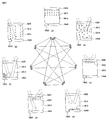
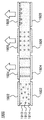
- FIG. 7 is a diagram conceptually illustrating a configuration of controlling spacing of particles according to the first embodiment of the first mode of the display device according to the present invention.
- FIG. 8 is a diagram conceptually illustrating a configuration of controlling a spacing of particles according to a second embodiment of a first mode of a display device according to the present invention.
- FIGS. 9 and 10 are views conceptually illustrating the configuration of display devices according to the first and second embodiments of the first mode of the display device according to the exemplary embodiment.
- FIG. 11 is a diagram exemplarily illustrating a configuration of a first mode according to an embodiment of the present invention.
- FIG. 12 is a diagram illustrating a configuration of a second mode of a display device according to an exemplary embodiment of the present invention.
- FIG. 13 is a diagram illustrating a configuration of a second mode of a display device according to an exemplary embodiment of the present invention.
- FIG. 14 is a diagram illustrating a configuration of a third mode of a display device according to an exemplary embodiment of the present invention.
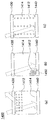
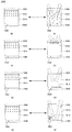
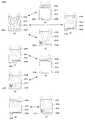
- 15 is a diagram illustrating a configuration of a display device capable of selectively performing first and second modes according to an embodiment of the present invention.
- FIG. 16 is a diagram illustrating a configuration of a display device capable of selectively performing first and third modes according to an embodiment of the present invention.
- 17 is a diagram illustrating a configuration of a display device capable of selectively performing second and third modes according to an embodiment of the present invention.
- FIG. 18 is a diagram illustrating a configuration of a display device capable of selectively performing first, second, and third modes according to an embodiment of the present invention.
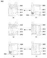
- FIG. 19 is a diagram illustrating a configuration of a display device driven by a plurality of electrodes according to an exemplary embodiment of the present invention.
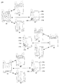
- FIG. 20 is a diagram illustrating a configuration of encapsulating particles and a solvent included in a display device into a plurality of capsules according to an exemplary embodiment of the present invention.
- FIG. 21 is a diagram illustrating a configuration in which particles and a solvent included in a display device are scattered in a medium according to an embodiment of the present invention.
- FIG. 22 is a view exemplarily showing the configuration of a solution encapsulated in a light transmissive medium according to an embodiment of the present invention.
- FIG. 23 is a diagram exemplarily illustrating a constitution of particles and a solvent scattered in a medium according to an embodiment of the present invention.
- FIG. 24 is a diagram illustrating a configuration in which particles and a solvent included in a display device are partitioned into a plurality of cells according to an embodiment of the present invention.
- 25 and 26 are diagrams exemplarily illustrating configurations in which display devices are coupled to each other in a vertical direction or a horizontal direction according to an exemplary embodiment.
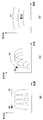
- 27 to 29 are diagrams exemplarily illustrating a pattern of voltages applied to a display device according to an exemplary embodiment.
- FIG. 30 is a diagram illustrating a circuit configuration connected to a plurality of electrodes of a display device according to an exemplary embodiment of the present invention.
- FIG. 31 is a diagram exemplarily illustrating a configuration for adjusting a display area of light reflected from particles according to an embodiment of the present invention.
- FIG. 32 is a diagram exemplarily illustrating a configuration for adjusting a display time of light reflected from particles according to an embodiment of the present invention.
- FIG 33 is a diagram exemplarily illustrating a configuration of adjusting brightness using a light adjusting layer according to an embodiment of the present invention.
- 34 and 35 are views exemplarily illustrating a configuration of a light adjusting layer for adjusting light transmittance according to an embodiment of the present invention.
- 36 is a diagram exemplarily illustrating a configuration of a light adjusting layer for adjusting a light blocking rate according to an embodiment of the present invention.
- FIG. 37 is a diagram exemplarily illustrating a configuration of a display device for implementing a photonic crystal display using particles having different charges according to an embodiment of the present invention.
- 38 to 40 are views exemplarily illustrating a configuration of patterning an electrode constituting an electrode according to an exemplary embodiment of the present invention.
- 41 is a diagram illustrating a configuration in which a display device according to an exemplary embodiment of the present invention includes a spacer.
- FIG. 42 is a diagram illustrating a configuration of a display device including a solar cell unit according to an embodiment of the present invention.
- FIG 43 is a diagram illustrating a configuration in which the display device according to the present invention is combined with a light emitting display device.
- Fig. 2 is a diagram showing the results of experiments in which the first mode of control is implemented in graphs and photographs.
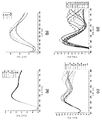
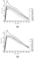
- FIG. 47 and FIG. 48 are reflections from particles as a result of experiments implementing the first mode by applying an electric field in a state in which charged particles are dispersed in various solvents having different polarity indices according to an embodiment of the present invention. It is a figure which shows the wavelength of the light made into a graph.
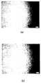
- 49 and 50 illustrate light reflected from particles as a result of experiments in which a first mode is implemented by applying an electric field in a state where particles having charge and electric polarization characteristics are dispersed in a solvent according to an embodiment of the present invention. It is a figure which shows as a graph and a photograph.
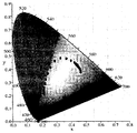
- FIG. 51 is a diagram illustrating a result of an experiment on a dependency of an observation angle (ie, a viewing angle of a display device) of a display device according to an exemplary embodiment.
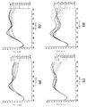
- FIG. 52 illustrates an experimental result of a display device for selectively switching one of the first and second modes so as to be switchable according to an embodiment of the present invention.
- 53 and 54 illustrate experimental results of a display device for selectively switching one of the first and third modes so as to be switchable according to an embodiment of the present invention.
- 55A, 55B, 55C, and 56 are diagrams illustrating experimental results of a display device for selectively switching between one of second and third modes, according to an exemplary embodiment.
- Fig. 57 shows an embodiment of the mode switching configuration between the second modes.
- 59 is a graph showing the relationship between wavelength, applied voltage and reflectivity for mode implementation and all transition implementations.
- the first mode represents a light crystal reflection mode
- the first mode may be a mode other than the light crystal reflection mode.
- the second mode may represent an intrinsic color reflection mode in the present specification
- the second mode may be other than the intrinsic color reflection mode in the claims.
- the third mode that is, in order to explain the present invention systematically, the respective modes are described herein with the first mode as the light crystal reflection mode, the second mode as the intrinsic color reflection mode, and the third mode as the transmittance adjustment mode. It is not limited only to description method.
- a display device applies an electric field through an electrode in a state in which a plurality of particles are dispersed in a solvent, and adjusts at least one of the intensity, direction, application time, frequency of application, and area of application of the particles.
- the first mode photonic crystal reflection mode
- the first mode displaying the color of the light reflected from the photonic crystal composed of the particles, the inherent color or scattering of the particles, such as particles, solvents, electrodes, etc.
- At least two modes of displaying the color of the solution by means of the second mode (unicolor reflection mode) and the third mode of displaying the color of the light whose transmittance is controlled i.e.
- a single pixel refers to the smallest display unit that can be controlled independently. That is, in the conventional display method, a single cell may be formed of a red cell, a green cell, and a blue cell, but this is, for example, three cells in a method of realizing color by mixing R, G, and B colors.
- a single pixel in the present specification is a minimum that can be controlled independently unlike a conventional method. It should be noted that the display unit or the display area or the display portion of the.
- FIGS. 1 and 2 are diagrams exemplarily illustrating a configuration of particles included in a display device according to an exemplary embodiment.
- the particles 110 may be dispersed in the solvent 120 and exist in a solution state.
- the particle 110 may have a positive charge or a negative charge. Therefore, when an electric field is applied to the particles 110, the particles 110 may be moved (ie, electrophoresis) due to electric charges generated by the electric charges and the electric fields of the particles 110.
- the plurality of particles 110 when the plurality of particles 110 have charges of the same sign, the plurality of particles 110 do not contact each other and maintain a predetermined interval due to mutual electrical repulsion (coulomb repulsion) due to charges of the same sign. It may be arranged as is.
- the particles 110 may be coated in the form of a polymer chain, such that a steric effect may be present due to disordered movement of the polymer chains between particles. Therefore, due to the intergranular hindrance effect, the plurality of particles 110 may be arranged while maintaining a predetermined interval without contacting each other.
- the particle 110 may be configured in the form of a core-shell 112 made of different materials as shown in FIG. As shown in (b) of FIG. 2, it may be configured in the form of a multi-core (multi-core) 114 made of heterogeneous materials, and as a cluster 116 of a plurality of nanoparticles as shown in FIG.
- the charge layer 118 having the above-described charge or the layer 118 exhibiting steric effect may be configured to enclose these particles.
- Particles according to the present invention is not limited to the above structure, it is possible to use a variety of particles and forms, such as a structure that penetrated or supported heterogeneous material in the core particles, raspberry structure, etc., the cavity such as backlight crystal structure Structures can also be used.
- the particle 110 is silicon (Si), titanium (Ti), barium (Ba), strontium (Sr), iron (Fe), nickel (Ni), cobalt (Co ), Lead (Pb), aluminum (Al), copper (Cu), silver (Ag), gold (Au), tungsten (W), molybdenum (Mo), zinc (Zn), zirconium (Zr) It may be made of a compound such as oxides, nitrides, and the like containing cow.
- the particle 110 comprises at least one unit of styrene, pyridine, pyrrole, aniline, pyrrolidone, acrylate, urethane, thiophene, carbazole, fluorene, vinylalcohol, ethylene glycol, ethoxy acrylate It may be made of an organic polymer or a polymer material such as PS (polystyrene), PE (polyethylene), PP (polypropylene), PVC (polyvinyl chloride), PET (polyethylen terephthalate).
- PS polystyrene
- PE polyethylene
- PP polypropylene
- PVC polyvinyl chloride
- PET polyethylen terephthalate
- the particle 110 may be configured as a form in which a material having a charge is coated on particles or clusters having no charge.
- the surface is processed by an organic compound having particles (carboxylic acid groups, ester groups, acyl groups), the surface is processed (or coated) by an organic compound having a hydrocarbon group ( Or coated) particles, particles whose surfaces are processed (coated) by a complex compound containing halogen (F, Cl, Br, I, etc.) elements, including amines, thiols, and phosphines.
- Particles whose surface is processed (coated) by the coordination compound, and particles having a charge by forming radicals on the surface may correspond thereto.
- the surface of the particle 110 may be coated with a material such as silica, a polymer, a polymer monomer, or the like, so that the particle 110 may have high dispersibility and stability in the solvent 120.
- the diameter of the particle 110 may be several nm to several hundred ⁇ m, but is not necessarily limited thereto.
- the refractive index of the particle may be changed by the Bragg law. It can be set to the size of the particles that can be included in the photonic crystal wavelength range of the visible region in conjunction with the refractive index of the solvent.
- the particle 110 may be configured to reflect light of a specific wavelength, that is, have a unique color. More specifically, the particle 110 according to an embodiment of the present invention may have a specific color through oxidation control or coating of inorganic pigments, pigments, and the like. For example, Zn, Pb, Ti, Cd, Fe, As, Co, Mg, Al, etc., including chromophores, in the form of oxides, emulsions, lactates, etc., are coated on the particles 110 according to the present invention.
- the dye to be coated on the particles 110 may be used as the dye to be coated on the particles 110 according to the present invention.
- the particle 110 may be a material having a specific structural color to display a specific color.
- particles such as silicon oxide (SiO x ) and titanium oxide (TiO x ) may be formed to be uniformly arranged at regular intervals in a medium having a different refractive index to reflect a light having a specific wavelength.
- the solvent 120 may also be configured to reflect light of a specific wavelength, that is, have a unique color. More specifically, the solvent 120 according to the present invention may include a material having an inorganic pigment, a dye or a material having a structural color by photonic crystal.
- At least one of a fluorescent material, a phosphor, and a light emitting material may be included in the particles or the solvent to maximize the effect of the present invention.
- the solvent 120 is dispersed in the solvent 120 in order to ensure that the particles 110 are uniformly dispersed in the solvent 120 to ensure colloidal stability.
- An additive such as a dispersant may be added to the solvent, or the difference in specific gravity between the particles 110 and the solvent 120 may be less than or equal to a predetermined value, the viscosity of the solvent 120 may be greater than or equal to a predetermined value, and the particles 110
- the value of the electrokinetic potential (ie, zeta potential) of the colloidal solution consisting of and a solvent 120 may be higher than a predetermined value.
- the solvent 120 and the particle 110 in order to increase the reflected light intensity of the visible light region generated through the predetermined arrangement in the solvent 120 when the particle 110 is applied to the electric field, the solvent 120 and the particle 110.
- the refractive index difference of) may be greater than or equal to a predetermined value, and the size of the particle 110 may be related to the refractive index of the particle and the refractive index of the solvent by Bragg's Law to include the photonic crystal wavelength band of the visible region.
- the absolute value of the interfacial potential of the colloidal solution may be 10mV or more
- the difference in specific gravity of the particle 110 and the solvent 120 may be 5 or less
- the particle size may be between 100nm ⁇ 500nm, but is not limited thereto.
- the solution including the solvent in which the particles included in the display device are dispersed may have a variable electrical polarization characteristic (the amount of electric polarization changes when an electric field is applied).
- the electrical polarization characteristics of such a solution may be at least one of the particles or the solvent constituting the solution exhibits the electrical polarization characteristics or electrical polarization characteristics by the interaction of the particles and the solvent in the solution.
- a solution consisting of particles and a solvent
- exhibiting electrical polarization characteristics may be electrically polarized by any one of electron polarization, ion polarization, interfacial polarization, and rotational polarization as an external electric field is applied due to an asymmetrical charge distribution of atoms or molecules. It may include a substance to be.
- At least one of the particles or the solvent or the solution composed thereof may cause electric polarization when an electric field is applied, and the induced electric polarization as the intensity or direction of the applied electric field is changed.
- the amount may change.
- the electric polarization amount changes as the electric field changes may be referred to as a variable electric polarization characteristic.
- the greater the amount of electric polarization induced when the electric field is applied the more advantageous, because the interaction force between the particles is greater by the electric polarization of at least one of the particles, solvents, solutions as the electric field is applied This is because the spacing between particles can be arranged more uniformly.
- FIG. 3 is a diagram illustrating a configuration in which particles or a solvent are polarized as an electric field is applied according to an embodiment of the present invention.
- the total electric polarization does not appear or shows a small value, but when an electric field is applied from the outside, particles or solvents having unit polarization may be rearranged in a predetermined direction according to the direction of the external electric field so that there is no unit polarization as a whole.
- a relatively large polarization value may be exhibited.
- the unit polarization shown in (c) and (d) of FIG. 3 may occur in an asymmetrical arrangement of electrons or ions or in an asymmetric structure of molecules, and due to such unit polarization, an external electric field is applied. If not, a fine residual polarization value may appear.
- Figure 4 is a diagram illustrating unit polarization characteristics by asymmetrical arrangement of molecules according to an embodiment of the present invention. More specifically, Figure 4 shows a case of water molecules (H 2 O) by way of example, in addition to the water molecules, trichloroethylene, carbon tetrachloride, Di-Iso-Propyl Ether, Toluene, Methyl-t-Bytyl Ether, Xylene, Benzene , DiEthyl Ether, Dichloromethane, 1,2-Dichloroethane, Butyl Acetate, Iso-Propanol, n-Butanol, Tetrahydrofuran, n-Propanol, Chloroform, Ethyl Acetate, 2-Butanone, Dioxane, Acetone, Metanol, Ethanol, Acetonitrile, Acetic Acid , Dimethylformamide, Dimethyl Sulfoxide, Propylene carbonate, N, N-Dimethyl
- the polarity index (polarity index) used to compare the polarization characteristics of the material, in contrast to the polarization characteristics of the water (H 2 O) may be an index indicating the relative degree of polarization of the material, one of the present invention
- the solvent may include a material having a polarity index of 1 or more.
- the particles or the solvent according to an embodiment of the present invention as the external electric field is applied, the electric polarization of the ions or atoms is further induced to increase the polarization amount, even if the external electric field is not applied, the residual polarization amount is present
- It may include ferroelectric materials that remain hysteresis depending on the direction of electric field application, and when the external electric field is applied, ionic or atomic polarization is additionally induced to increase the amount of polarization, but when no external electric field is applied. It may include superparaelectric materials that do not leave residual polarization and hysteresis. Referring to FIG. 5, a hysteresis curve according to an external electric field of the paraelectric material 510, the ferroelectric material 520, and the superphase dielectric material 530 may be checked.
- the particles or the solvent according to an embodiment of the present invention may include a material having a perovskite structure, ABO 3 PbZrO as a material having a perovskite structure such as 3 , PbTiO 3 , Pb (Zr, Ti) O 3 , SrTiO 3 BaTiO 3 , (Ba, Sr) TiO 3 , CaTiO 3 , LiNbO 3 Examples thereof may be mentioned.
- ABO 3 PbZrO as a material having a perovskite structure such as 3 , PbTiO 3 , Pb (Zr, Ti) O 3 , SrTiO 3 BaTiO 3 , (Ba, Sr) TiO 3 , CaTiO 3 , LiNbO 3 Examples thereof may be mentioned.
- FIG. 6 is a view exemplarily showing a material having a perovskite structure that may be included in particles or a solvent according to an embodiment of the present invention.
- the position of PbZrO 3 (or PbTiO 3) PbZrO depending on the direction of the external electric field is applied to the third (or PbTiO 3) Zr (or Ti) (that is, B of the ABO 3 structure) in the This may cause the polarity of the entire PbZrO 3 (or PbTiO 3 ) to be changed. Accordingly, asymmetric electron distribution may be formed by the movement of atoms or ions, thereby forming unit polarization. If such unit polarization is present, the variable electric power is greater when an external electric field is applied than when only the electron polarization is present. Can cause polarization values.
- the microparticles are dispersed in the non-conductor fluid so that the electro-rhoheology (ER) characteristics
- a fluid indicating or even a fluid indicating a maximum electro- rheology (GER) such as ferroelectric particles coated with an insulator can maximize the effect of the present invention.
- each molecule and each particle of the solvent has no electric polarization amount, but if the electric field is applied to each molecule and each At least one of the particles is electrically polarized, whereby at least one of the total electrical polarization amount of the plurality of particles and the total electrical polarization amount of the solvent may be increased.
- at least one of each molecule and each particle of the solvent is electrically polarized, but at least one of the total amount of electrical polarization of the solvent and the total amount of electrical polarization of the plurality of particles is zero.
- At least one of the total electric polarization amount of the plurality of particles and the total electric polarization amount of the solvent may be increased.
- at least one of each molecule and each particle of the solvent is electrically polarized such that at least one of the total amount of electrical polarization of the solvent and the total amount of electrical polarization of the plurality of particles is zero.
- at least one of the total electric polarization amount of the plurality of particles and the total electric polarization amount of the solvent may be a second value greater than the first value.
- Interparticle repulsive force Coulomb effect or steric hindrance effect
- the surface of the particles included in the display device is charged with a charge of the same sign to form a coulomb repulsive force, or a polymer chain structure, a functional group, an additive, or the like on the surface of the particles.
- the steric hindrance repulsion may be formed by forming a three-dimensional structure and the like.
- the charge of the same code and the coating of the particles in the form of a three-dimensional structure may also induce the colon repulsion and steric repulsion at the same time.
- the particles include a material that is electropolarized and the surface of the particles through the steric hindrance repulsion, but the charge is weak to configure the electrophoretic effect to minimize the particle or solution,
- the amount of electric polarization changes according to the external electric field, effectively causing local short range attraction between particles, and the local short range steric hindrance repulsion between particles is effectively caused by the three-dimensional structure formed through particle surface treatment.
- an organic ligand can be treated on the particle surface.
- an alternating current voltage may be used in combination.
- composition of the particles and the solvent according to the present invention is not necessarily limited to those listed above, but within the range in which the object of the present invention can be achieved, that is, within the range in which the spacing of the particles can be controlled by an electric field. Note that changes can be made as appropriate.
- the difference in refractive index between the particles and the dispersed solution is increased, and when no voltage is applied, the diffuse reflection (scattering) is maximized to increase the opacity and voltage is applied to the structure color.
- the reflectance of the structural color can be increased.
- a method of maximizing the refractive index of the particles is effective, and a core / shell or raspberry structure in which two or more different materials are combined.
- a display device may be configured to apply an electric field through an electrode in a state where a plurality of particles are dispersed in a solvent, and to adjust the spacing of particles by adjusting at least one of the intensity, direction, number of application times, and application time of the electric field.
- the first mode in which the color of the light reflected from the particle structure (i.e., the photonic crystal formed by maintaining the predetermined intervals of the plurality of particles) is variably displayed.
- the first mode may be referred to as a photonic crystal reflection mode.
- light may also be transmitted in the reflection mode (photonic crystal reflection mode and intrinsic color reflection mode (to be described later and corresponding to the second mode)).
- the use of transmitted light is negligible because it uses reflected light which is dominant in this reflection mode.
- the primary dominant occurrence in the transmittance control mode which is a third mode to be described later, is transmitted light, the use of the reflected light is also ignored in this case.
- the first mode may be a mode other than the photonic crystal reflection mode, which is merely for systematic explanation, and the present invention should not be limited thereto.
- the first mode of the display device when an electric field is applied to the particles and the solvent in a state in which a plurality of particles having the same charge charge are dispersed in a solvent having electrical polarization characteristics, Due to the charges of the particles, an electric force is applied to the plurality of particles in proportion to the intensity of the electric field and the amount of charge of the particles. Accordingly, the plurality of particles are electrophoresis and move in a predetermined direction, thereby narrowing the spacing of the particles. .
- the spacing of the particles becomes narrower, the electrical repulsive force generated between the plurality of particles having the same charge with each other increases, so that the spacing of the particles does not continue to be narrowed, thereby achieving a predetermined balance and thus the plurality of particles.
- the particles of can be arranged at regular intervals.
- the solvents around the charged particles are electropolarized and influence each other.
- the electric polarization of the solvent is arranged in the direction of the external electric field.
- Charge-charged particles that are interrelated with electropolarization can also be arranged in the direction of an external electric field.
- the unit polarized solvent is arranged in a predetermined direction by the electric field applied from the outside and the electric charges of the surrounding particles, thereby forming a polarization region formed locally around the particles so that a plurality of particles are separated by a predetermined interval. It can be arranged more regularly and stably with the state maintained.
- a plurality of particles can be arranged regularly at a distance at which an electric force (coulomb force) or the like forms an equilibrium.
- the spacing of the particles can be controlled at a predetermined interval, and the plurality of particles arranged at a predetermined interval can function as a photonic crystal. Since the wavelength of the light reflected from the plurality of particles arranged regularly is determined by the spacing of the particles, the wavelength of the light reflected from the plurality of particles can be arbitrarily controlled by controlling the spacing of the particles by controlling the external electric field. .
- the pattern of the wavelength of the reflected light depends on factors such as the intensity and direction of the electric field, the size and mass of the particles, the refractive index of the particles and the solvent, the amount of charge of the particles, the electrical polarization characteristics of the solvent or particles, and the concentration of dispersed particles in the solvent. It can appear variously.
- FIG. 7 is a diagram conceptually illustrating a configuration of controlling a spacing of particles according to an embodiment of a first mode of a display device according to the present invention.
- the unit polarized solvent 710 around the charged particles 720 interacts with the charges of the particles, so that they are strongly arranged in the direction of the particles, and the distance from the particles is increased.
- the unit polarized solvents 710 may be arranged in an orderly manner (see FIG. 7A).
- FIG. 7A when an external electric field is applied, the unit polarized solvent 710 located in a region where the influence of the charge of the particles 720 is not affected (that is, a region far from the particles 720).
- the charged particles 720 may be rearranged due to the influence of the rearranged solvents. That is, the unit polarized solvent 710 located in the region where the electrical attractive force by the charged particles is strongly acting (that is, the region adjacent to the particle 720) is the electrical attractive force due to the charge of the particles 720. Due to this, the anode or the cathode of the unit polarization may be arranged in a direction facing the particles 720, and thus the unit polarization solvent 710 of the peripheral region of the particles 720 is arranged in the direction facing the particles 720.
- the region, ie, the polarization region 730 can act as one large particle that is electrically polarized to interact with other surrounding polarization regions, so that charged particles 720 are spaced at a predetermined interval. It can be arranged regularly (see FIG. 7B).
- FIG. 7 is a schematic diagram of a solvent having residual polarization, but may be similarly applied to a solvent having an electric polarization characteristic as an electric field is applied even in the absence of residual polarization.
- the electrical repulsive force generated between the plurality of particles having the same charge with each other increases, so that the spacing of the particles does not continue to be narrowed, thereby achieving a predetermined balance and thus the plurality of particles.
- the particles of can be arranged at regular intervals.
- the particles exhibiting electrical polarization characteristics are polarized by an electric field to be polarized in the direction of the electric field, and electrical attraction is locally generated between the plurality of polarized particles so that the plurality of particles maintain a predetermined interval. It can be arranged more regularly and stably.
- the electric attraction force (electrophoretic force) due to the external electric field the electric repulsive force (Coulomb repulsion force) between the particles having the same charge with each other and the electric attraction force due to polarization
- a plurality of particles can be arranged regularly at a distance at which the coulombs form an equilibrium.
- the spacing of the particles can be controlled at a predetermined interval, and the plurality of particles arranged at a predetermined interval can function as a photonic crystal.
- the wavelength of the light reflected from the plurality of particles arranged regularly is determined by the spacing of the particles
- the wavelength of the light reflected from the plurality of particles can be arbitrarily controlled by controlling the spacing of the particles.
- the pattern of the wavelength of the reflected light depends on factors such as the intensity and direction of the electric field, the size and mass of the particles, the refractive index of the particles and the solvent, the amount of charge of the particles, the electrical polarization characteristics of the particles and the solvent, and the concentration of the dispersed particles in the solvent. It can appear variously.
- FIG. 8 is a diagram conceptually illustrating a configuration of controlling a spacing of particles according to an embodiment of a first mode of a display device according to the present invention.
- the particles 810 when the external electric field is not applied, the particles 810 are not polarized (see FIG. 8A), but when the external electric field is applied, electricity of the material contained in the particles 810 is applied. Due to the polarization characteristic, the particles 810 may be polarized, and thus the particles 810 may be regularly arranged with a predetermined interval (see FIG. 8B).
- the greater the electrical polarization value of the solvent or particles the greater the degree of interaction between the polarization zone 730 or the polarized particles 810, so that the particles are arranged more regularly. You can do it. 8 illustrates particles having no residual polarization, but may be similarly applied to particles having a characteristic in which electrical polarization changes as an electric field is applied even in a state where residual polarization is present.
- the display device according to an exemplary embodiment of the present invention is described.
- the configuration of the display device according to the exemplary embodiments of the first mode of FIG. 9 is conceptually shown in FIGS. 9 and 10, respectively. Since the above embodiments of the first mode of the display device according to the exemplary embodiment of the present invention have been described in detail with reference to FIGS. 7 and 8, additional descriptions of FIGS. 9 and 10 will be omitted.
- the particles or the solvent have the electrical polarization characteristic
- the particles or the solvent according to the present invention do not necessarily have the electrical polarization characteristics. That is, even when a particle or a solvent does not have electrical polarization characteristics, if the particle has a charge, the plurality of electric charges due to an external electric field and the electric repulsive force between a plurality of particles having a charge of the same sign are balanced with each other.
- the particles of may be arranged regularly, and the plurality of regularly arranged particles may form a photonic crystal that reflects light of any wavelength.
- the spacing between the plurality of particles can be maintained at a constant interval by the balance of the attractive force and the repulsive force acting between the particles as described above according to the external electric field, but the attractive force and the repulsive force may effectively act between the near particles.
- the arrangement of particles according to the present invention may show short range ordering rather than long range ordering in three dimensions. have.
- the reflected light reflected by the set of short-range arrays having slightly different arrangements may exhibit the reflected light characteristic having a significantly improved viewing angle dependency compared to the photonic crystal light reflected by the conventional photonic crystal array.
- the particles according to the present invention do not necessarily have a charge. That is, even if a particle has an electric polarization characteristic and has a three-dimensional structure capable of generating steric hindrance repulsion even when the particle has no electric charge, the electrical attraction between adjacent particles caused by the electric polarization caused by an external electric field and
- the plurality of particles may be regularly arranged at a distance where the repulsive force due to the steric hindrance effect is balanced, and the plurality of regularly arranged particles may form a photonic crystal that reflects light of any wavelength.
- FIG. 11 is a diagram exemplarily illustrating a configuration of a first mode according to an embodiment of the present invention.
- the greater the intensity of the applied electric field the narrower the interval between the particles 1112, and thus the shorter the wavelength of light reflected from the photonic crystal made of the particles 1112.
- the lower electrode is divided into a large electrode and a small electrode, but the present invention is not limited thereto, but the lower electrode may be integrally formed.
- the electrode may be divided or integrated according to each embodiment, and according to the following description, it will be understood in which mode switching embodiments that the electrode needs to be integrated and the electrode needs to be divided.
- mode switching embodiments that the electrode needs to be integrated and the electrode needs to be divided.
- the present invention switches modes in the same single pixel, the structure of the corresponding electrode should not be changed.
- the voltage applied to implement the first mode may be a DC voltage or an AC voltage including an AC voltage or a DC component.
- the electrical polarization characteristic or the variable electrical polarization characteristic described above can occur both when an alternating voltage or a direct current voltage is applied.
- a direct voltage is applied to the charged particles, the charged particles are reversed by electrophoresis.
- the screen phenomenon caused by the concentrated charge affects other particles, and the particles are gradually changed in electrophoretic force, and as a result, gradually different in the direction of the electric field.
- the distance may be maintained, and the display unit may have a good viewing angle by having only short-range regularity rather than long-range regularity. This viewing angle characteristic will be described later.
- the particles when the voltage is not applied, the particles are randomly dispersed to show the solution color. However, even when no voltage is applied because the concentration of the particles is higher than a predetermined value, the interaction force between particles is If sufficient, a certain spacing can be maintained by interparticle interaction without applying a voltage.
- an electric field is applied through an electrode in a state where a plurality of particles are dispersed in a solvent, and at least one of the intensity, direction, application time, frequency of application, and application region of the electric field is adjusted.
- the position of the particles, the color of the solution, or the color of the electrode due to light scattering of the particles or the intrinsic or retaining color of the particles or solvent is variably indicated.
- the electrode color is to specify the color of the material under the transparent electrode appearing through the transparent electrode
- the second mode is an intrinsic color reflection mode or a retention color reflection mode. May be referred to.
- the intrinsic color may mean a color that is reflected when the material of the particle, the solvent, or the electrode is irradiated with white light.
- electrophoresis electrophoresis
- DEP dielectric electrophoresis
- Such electrophoresis and dielectric electrophoresis may occur more effectively when DC voltage is applied to the dispersed solvent.
- the electric field is applied to the plurality of particles due to the charge of the particles.
- An electrical attraction is applied in proportion to the intensity of the particles and the amount of charge of the particles.
- the plurality of particles are electrophoresis to move in a predetermined direction.
- the plurality of particles do not form a photonic crystal as in the first mode and move toward the local region of the electrode to which the electric field is applied.
- FIG. 12 is a diagram illustrating a configuration of a second mode of a display device according to an exemplary embodiment of the present invention.
- the particles when the electric field is not applied, the particles may be irregularly dispersed in the solvent to display the color of the solution in which the intrinsic colors of the particles and the solvent are mixed (see FIG. 12A). Namely, a solution color reflection mode in which the color of the solution due to light scattering by the particles appears), and the particle 1210 is moved toward the upper electrode 1230 on the observer side, so that the particle 1210 has its own Color may be displayed (see FIG. 12A).
- the first lower electrode 1240 (large area) where the particle 1210 is opposite the observer and has a large area;
- the inherent color of the solvent 1220 can be displayed (see FIG. 12 (c)) (solvent color reflection Mode)
- particles 1210 may be opposite to the observer
- the second lower electrode which may be referred to as a local electrode or a small electrode
- the first lower electrode 1240 may be A unique color may be displayed (see (d) of FIG.
- the lower electrode 12 (referred to as an electrode color reflection mode), if the first lower electrode 1240 is transparent, the lower electrode is displayed through the transparent lower electrode.
- the lower electrode is divided into a large electrode 1240 and a small electrode or a local electrode 1250, but the color of the material of FIG.
- the solution color reflection mode, the particle color reflection mode, and the solvent color reflection mode corresponding to (c) the lower electrode may be an integral structure, and the small electrode or the local electrode 1250 is shown in FIG. But next to it It may appear as if the counter electrode occupies the whole of the lower electrode when viewed from above because it is very small compared to the electrode 1240.
- the lower electrode is divided into a large electrode and a small electrode
- the upper electrode is The structure divided into this large electrode and the small electrode can also be considered.
- the particle color reflection mode may be implemented by applying a voltage only to the large electrode, and also in the electrode color reflection mode, it may be implemented by applying a voltage only to the small electrode.
- the embodiment implementing the intrinsic color reflection mode of the present invention is not limited to FIG. 12 but various modifications are possible.
- Dielectric phenomena are characterized by uninduced dipole moments of uncharged dielectric particles in a dielectric medium with a non-uniform electric field, and the forces exerted on the dielectric particles by the difference between the dielectric constant of the dielectric particles and the dielectric constant of the dielectric medium. It is a phenomenon that the electric field gradient is moved to a large area or a small area. Therefore, dielectric particles having a dielectric constant greater than the dielectric constant of the dielectric medium move to a region having a large electric field gradient, and dielectric particles having a dielectric constant smaller than the dielectric constant of the dielectric medium move to a region having a small electric field gradient.
- FIG. 13 is a diagram illustrating a configuration of a second mode of a display device according to an exemplary embodiment of the present invention.
- the lower electrode is divided into the first lower electrodes 1332 and 1335 and the second lower electrode 1334.
- the particles 1312 are irregularly dispersed in the solvent 1314.
- the unique color of the solution can be displayed.
- FIG. 13B voltages are applied to the first lower electrode 1332 and 1335 and the second lower electrode 1334 so that the first lower electrodes 1332 and 1335 have a positive sign.
- the slope of the electric field generated in the space between the first lower electrodes 1332 and 1335 and the second lower electrode 1334 is displayed. Since the particles are much higher than the electric field gradients generated in other regions within the particles, the particles 1312 are moved due to the electrophoresis and are concentrated in the space between the first lower electrodes 1332 and 1335 and the second lower electrode 1334. Inherent colors of the first lower electrodes 1332 and 1335 or the second lower electrodes 1334 may be displayed.
- the first mode described above operates according to the principle of the photonic crystal for selectively reflecting light of a specific wavelength among the light incident on the display device, it is not easy to realize a completely white or black color. Therefore, when the combination of white or black particles, solvents or electrodes in the second mode, it is possible to realize a perfect white or black color of the intrinsic color of the particles, solvents or electrodes, the disadvantage of the first mode as described above It can be supplemented. More specifically, when white particles are used and a black electrode (the electrode material is black or a black substance is located at the bottom of the transparent lower electrode), the particle color of white and the electrode color of black are changed according to the mode change described above. May be selectively implemented in the same display area or the same unit pixel or pixels.
- a third mode of the display device an electric field is applied through an electrode in a state in which a plurality of particles are dispersed in a solvent, and the intensity, direction, application time, frequency of application, and application area of the electric field are adjusted.
- the third mode of the display device is to adjust the wavelength of the reflected light by the photonic crystal (photonic crystal transmittance control mode), to move the particles using electrophoresis or dielectric electrophoresis (particle dynamic transmittance control mode) or particles It can be implemented by controlling the arrangement state of the (particle alignment permeability control mode).
- the third mode may be referred to as a transparency control mode.
- the reflected light may exist in the present transmittance adjusting mode, the light that is dominantly generated in the present mode and can be sensed by the viewer is once again transmitted.
- FIG. 14 is a diagram illustrating a configuration of a third mode of a display device according to an exemplary embodiment of the present invention.
- a particle structure is applied by applying an electric field through an electrode in a state in which a plurality of particles are dispersed in a solvent, and adjusting the spacing of particles by adjusting at least one of the intensity and direction of the electric field.
- the intensity of the electric field applied to the particles in controlling the wavelength of light reflected from a photonic crystal formed by maintaining a predetermined interval of a plurality of particles, by adjusting the intensity of the electric field applied to the particles to make the spacing of the particles narrower or wider than the threshold value from the particles
- the color of the display device can be made transparent in the visible region by adjusting the electric field so that the wavelength range of the reflected light is in the ultraviolet or infrared band instead of the visible ray band.
- the light transmittance can be adjusted by making the light reflected from the photonic crystal made of particles transparent.
- light transmittance mainly means light transmittance in the visible light region.
- This manner may be referred to herein as a photonic crystal transmittance control mode.
- Such a photonic crystal transmittance control mode may occur at both a DC voltage and an AC voltage, and may be more effective when the solution in which the particles are dispersed has the above-described variable electrical polarization characteristics.
- ferroelectric or superphase dielectric particles having excellent electrical polarization properties are used, the arrangement of particles is more effectively represented due to the interaction between the polarized particles when an external electric field is applied, thereby obtaining more intense permeability.
- an electric field is applied to particles moving by electrophoresis or particles moving by electrophoresis to concentrate the particles on an electrode having a relatively small area. It is possible to control the light transmittance by preventing the incident light from being reflected or scattered by the particles.
- the light transmittance may be controlled by adjusting the density at which particles are concentrated on the lower local electrode. For example, a configuration in which the transmittance of light passing through the particles and / or the solvent is controlled by adjusting the density at which particles are concentrated on the local electrode after installing the local electrode in the center portion of the lower electrode may also be considered.
- Such a mode may be referred to herein as a particle drift transmittance control mode, and this mode may be more effectively performed when a direct current voltage is applied, and the transmittance may be adjusted according to a time or a number of times when a direct current voltage is applied.
- the plurality of particles when an electric field is applied to the particles and the solvent in a state in which the plurality of particles having the electrical polarization characteristics are dispersed in the solvent, the plurality of particles may be polarized by the electric field and thus the electric field. According to the direction of, all can be polarized in the same direction, because the electrical attraction occurs between a plurality of particles polarized in the same direction, the plurality of particles dispersed in the solvent pulls each other in a direction parallel to the direction of the electric field Can be arranged regularly.
- this mode may be referred to as a particle array or alignment transmittance control mode, and this mode may also be implemented as a direct current voltage.
- an alternating current voltage may be applied to prevent the phenomenon of bias toward the electrode due to electrophoresis when the direct current voltage is applied. Is preferably implemented.
- particles may move toward the electrode by electrophoresis due to electrophoresis to reflect light of the intrinsic color of the particles or to concentrate on one side of the electrode. May be advantageously applied.
- FIG. 15 is a diagram exemplarily illustrating a configuration of a display device capable of selectively switching between first and second modes in the same single pixel or cell, according to an exemplary embodiment.
- a display device 1500 may include a display unit 1510 and an electrode 1520. More specifically, the display unit 1510 may include a plurality of particles 1512 dispersed in the solvent 1514, and the electrode 1520 may include the upper electrode 1522, the lower electrode 1524, and the local electrode 1526. It may include. In addition, the particles 1512 included in the display unit 1510, the solvent 1514, and the lower electrode 1524 covering the lower portion of the display unit 1510 may have unique colors. In the present specification, for the sake of explanation, the display unit and the electrode have been described separately, but it is obvious that the electrode may be included in the display unit.
- the display device may selectively perform any one mode of the first mode and the second mode so as to be switched with each other within the same single pixel. More specifically, the display device according to an exemplary embodiment of the present invention may apply an electric field and adjust at least one of the intensity and the direction of the electric field through the electrode in a state in which the plurality of particles are dispersed in the solvent, and accordingly, the spacing of the particles. Control the wavelength of the light reflected from the photonic crystal made of particles (first mode), or control the position of the particles to control the color of the solution (i.e. the color of the solution by light scattering of the particles), Can perform the function of displaying the unique color having (second mode). In the following, the color of the solution may be considered to include the color of the solution by light scattering of the particles.
- the display device 1500 provides a strength of a direct current (DC) electric field applied to a solution exhibiting variable polarization characteristics through the electrodes 1522 and 1524.
- DC direct current
- the wavelength of the light reflected from the particles 1512 i.e., color
- the direction of the particles 1512 first mode.
- the plurality of particles 1512 have the same charge, the electrical attraction due to the external electric field, the electrical repulsive force between the particles 1512 having the same charge as each other, and the electrical attraction due to the polarization by the external electric field, etc.
- the plurality of particles 1512 may be regularly arranged at a distance of (), and the plurality of particles 1512 arranged at a predetermined interval may function as a photonic crystal.
- the plurality of particles 1512 has a three-dimensional obstacle that can cause a steric hindrance effect, the repulsive force between the particles due to the steric hindrance effect and the electrical attraction due to polarization by an external electric field, etc., form a distance (equilibrium)
- the plurality of particles 1512 may be regularly arranged, and the plurality of particles 1512 arranged at predetermined intervals may function as photonic crystals.
- the repulsive force due to charge and repulsion due to steric hindrance The effect can also be expressed simultaneously.
- the display device 1500 controls the spacing of the particles 1512 by adjusting the intensity or direction of an alternating current (AC) electric field or an alternating frequency applied through the electrodes 1522 and 1524.
- the wavelength (ie, color) of the light reflected from the particles 1512 can be adjusted (first mode).
- mutual attraction between particles is generated in accordance with the electrical polarization generated according to the applied alternating voltage, and mutual repulsive force is generated by a layer generating an equally charged charge or intergranular interference effect on the particle surface. Can be generated to keep particles at a certain distance by the balance of attraction and repulsion. Therefore, in the case of applying the AC voltage, the generated electrical polarization should be applied in the frequency range which can be sufficiently changed according to the frequency of the AC voltage.
- the wavelength of the light reflected from the plurality of particles 1512 arranged at regular intervals is determined by the spacing of the particles 1512, the intensity and direction of the electric field applied through the electrode 1520 is controlled.
- the spacing of the particles 1512 By controlling the spacing of the particles 1512, the wavelengths of the light reflected from the plurality of particles 1512 can be arbitrarily controlled.
- the display device 1500 adjusts the strength or direction of a direct current (DC) electric field applied through the electrodes 1522, 1524, and 1526, but the intensity of the electric field is greater than or equal to a certain threshold.
- DC direct current
- the particles 1512 are irregular in the solvent 1514.
- the color of the solution which is dispersed and appears by mixing the inherent color of the particles 1512, the intrinsic color of the solvent 1514, and the color of light reflected or scattered from the particles 1512 or the solvent 1514, can be displayed.
- the mutual switching between the photonic crystal reflection mode of FIG. 15A and the solution color reflection mode of FIG. 15B may be implemented by the intensity of the applied voltage. That is, the applied voltage used in the photonic crystal reflection mode may be greater than the applied voltage used in the solution color reflection mode.
- the lower electrode may be integrated without being divided.
- the plurality of particles 1512 have electric charges and the upper electrode 1522 has an electrode opposite to the electric charges of the particles 1512.
- the particles 1512 are moved toward the upper electrode 1522 by electrophoresis, and thus, a unique color of the particles 1512 is displayed on the display unit 1510. Can be.
- the mutual switching between the light crystal reflection mode of FIG. 15A and the particle color reflection mode of FIG. 15C may be implemented by the intensity of the applied voltage. That is, the applied voltage used in the photonic crystal reflection mode may be smaller than the applied voltage used in the particle color reflection mode.
- the photonic crystal mode of FIG. 15 may be implemented using an AC voltage
- FIG. 15C may be implemented by applying a DC voltage. That is, the mode can also be switched by changing the form of the voltage (direct current or alternating current).
- the lower electrode may be integrated without being divided.
- the plurality of particles 1512 have electric charges and the lower electrode 1524 has an electrode opposite to the electric charges of the particles 1512.
- the particles 1512 are moved toward the lower electrode 1524 by electrophoresis, and thus, a unique color of the solvent 1512 is displayed on the display unit 1510. Can be.
- the mutual switching between the photonic crystal reflection mode of FIG. 15A and the solvent color reflection mode of FIG. 15D may be implemented by the direction of the applied voltage. That is, when the charged particles move to the upper electrode, the photonic crystal reflection mode is implemented according to the intensity of the electric field, and when the charged particles move to the lower electrode, the solvent color reflection mode may be implemented. have.
- the lower electrode may be integrated without needing to be divided as shown in FIG. 15.
- a plurality of particles 1512 have a charge and a local electrode 1526 has an electrode opposite to that of the particles 1512.
- the particles 1512 are concentrated and positioned around the local electrode 1526, thereby lowering the electrode 1524 on the display unit 1510.
- Inherent color if the lower electrode is transparent, the color of the material under the lower electrode
- the switching between the photonic crystal reflection mode of FIG. 15A and the electrode color reflection mode of FIG. 15E may be implemented by an application region to which an applied voltage is applied. That is, in the photonic crystal reflection mode, the electric field is uniformly applied, but in the electrode color reflection mode, only the local region of the display electrode may be applied. The intensity of the applied electric field may be that the light crystal reflection mode is weaker than the electrode color reflection mode.
- the lower electrode may not be divided and the upper electrode may be divided, and the shape of the divided electrode is not limited to FIG. 15. It may be applied to various forms or only to a plurality of local areas.
- the color of the solvent, the particle, and the electrode (the color of the material under the lower electrode in the case of the transparent electrode) is used in combination of white and black, so that the color and the color of the continuous color in the same single pixel or the same display area can be Both black and black can be rendered.
- the particles have a charge of the same sign.
- a second mode may be performed in which particles are irregularly dispersed in the solvent to display the color of the solution.
- the electric field is a direct current electric field and the intensity of the direct electric field is adjusted within a range capable of regularly controlling the spacing of the particles
- the first wavelength of the wavelength of light reflected from the particles is adjusted within the visible light band according to the intensity of the direct current electric field. The mode can be performed.
- the particles are concentrated on the upper electrode and the color of the particles is displayed or the particles are concentrated on the lower electrode.
- the second mode may be performed in which the color of the solvent is displayed or the particles are concentrated on the local electrode to display the color of the upper electrode or the lower electrode.
- the wavelength of the light reflected from the particles according to the intensity or frequency of the alternating electric field is within the visible range.
- the first mode to be adjusted may be performed.
- the frequency as well as the strength of the alternating voltage may also be a variable used to control the particle spacing in the photonic crystal mode.
- the photonic crystal reflection mode may be implemented by applying an alternating voltage, and in the solvent color reflection mode, the particle color reflection mode, and the electrode color reflection mode, the DC voltage may be implemented in the second mode. In this case it may be easier to implement the photonic crystal mode when the solution (particle or solvent or combination thereof) exhibits electrical polarization properties.
- another case includes a structure in which particles have an electric polarization characteristic (electric polarization is induced when an electric field is applied and the amount of electric polarization changes as the applied electric field is changed) and generates a steric hindrance effect.
- a second mode may be performed in which the particles are irregularly dispersed in the solvent to display the color of the solution.
- the electric field is a direct current electric field and the intensity of the direct electric field is adjusted within a range capable of regularly controlling the spacing of the particles
- the first wavelength of the wavelength of light reflected from the particles is adjusted within the visible light band according to the intensity of the direct current electric field.
- the mode can be performed.
- the particles concentrate on the upper electrode.
- the second mode may be performed such that the color of the particles is displayed or the particles are concentrated on the lower electrode so that the color of the solvent is displayed or the particles are concentrated on the local electrode so that the color of the upper electrode or the lower electrode is displayed.
- the wavelength of the light reflected from the particles according to the intensity or frequency of the alternating electric field is within the visible range.
- the first mode to be adjusted may be performed.
- the light color reflection mode, the particle color reflection mode, the electrode color reflection mode, or the solvent color reflection mode may be switched from the photonic crystal reflection mode to the solution color reflection mode, the particle color reflection mode, and the electrode color. Switchable between reflection mode and solvent color reflection mode. The configuration thus switched between the second modes will be described below.
- FIG. 16 is a diagram exemplarily illustrating a configuration of a display device capable of selectively performing switchable first and third modes within the same single pixel, according to an exemplary embodiment.
- a display device 1600 may include a display unit 1610 and an electrode 1620. More specifically, the display unit 1610 may include a plurality of particles 1612 dispersed in the solvent 1614, and the electrodes 1620 may include the upper electrode 1622, the lower electrode 1624, and the local electrode 1626. It may include. In addition, the upper electrode 1622, the lower electrode 1624, and the local electrode 1626 may all be made of a light transmissive material to transmit light incident to the display device 1600.
- the display device may selectively perform any one of the first mode and the third mode so as to be switchable with each other. More specifically, the display device according to the exemplary embodiment may apply an electric field and adjust at least one of the intensity and the direction of the electric field through the electrode in a state in which the plurality of particles are dispersed in the solvent, and thus the spacing of the particles. Control the wavelength of light reflected from the photonic crystal made of particles (first mode), or control the spacing, position or arrangement of the particles to adjust the transmittance of light incident on the display device (third mode). Can be.
- the display device 1600 adjusts the strength or direction of a direct current (DC) electric field applied through the electrodes 1622 and 1624 to adjust the particle (
- DC direct current
- the wavelength (ie, color) of the light reflected from the particles 1612 can be adjusted (first mode).
- a plurality of particles 1612 may be regularly arranged at a distance in which an electrical attraction due to polarization by the equilibrium (equilibrium) to form an equilibrium, the plurality of particles 1612 arranged at a predetermined interval to function as a photonic crystal. You can do it.
- the plurality of particles 1612 when the plurality of particles 1612 has a three-dimensional obstacle that can cause a steric hindrance effect, the repulsive force between the particles due to the steric hindrance effect and the electrical attraction due to polarization by an external electric field, etc., form a distance (equilibrium)
- the plurality of particles 1612 may be regularly arranged, and the plurality of particles 1612 arranged at a predetermined interval may function as a photonic crystal.
- the display device 1600 controls the spacing of the particles 1612 by adjusting the strength, direction, or frequency of an alternating current (AC) electric field applied through the electrodes 1622 and 1624.
- the wavelength (ie, color) of the light reflected from the particle 1612 can be adjusted (first mode).
- the wavelength of the light reflected from the plurality of particles 1612 arranged at regular intervals is determined by the spacing of the particles 1612, the intensity and direction of the electric field applied through the electrode 1620 is adjusted.
- the spacing of the particles 1612 By controlling the spacing of the particles 1612, the wavelengths of the light reflected from the plurality of particles 1612 can be arbitrarily controlled.
- the display device 1600 controls the spacing, position or arrangement of particles by adjusting the intensity or direction or the application position of an electric field applied through the electrodes 1622, 1624, and 1626.
- the transmittance of light incident on the display device may be controlled (third mode or transmittance control mode).
- an electric field having an intensity above or below a specific threshold is applied to a photonic crystal composed of particles 1612 disposed at predetermined intervals.
- Light in the ultraviolet or infrared band is reflected from the photonic crystal made of particles 1612, but the light in the visible band is not reflected, so that the light in the visible band entering the display device 1600 causes the display device 1600 to have high light. It is possible to transmit at a transmittance.
- This mode may be referred to as a light crystal transmittance control mode as described above.
- the mutual switching between the photonic crystal reflection mode of FIG. 16 (a) and the photonic crystal transmittance control mode of FIG. 16 (b) may be implemented by the intensity of the applied voltage. That is, the applied voltage used in the photonic crystal reflection mode may be greater than or smaller than the applied voltage used in the photonic crystal transmittance adjustment mode.
- the photonic crystal transmittance control mode of ultraviolet light may have a higher applied voltage than in the photonic crystal reflection mode, and the photonic crystal transmittance control mode of infrared light is reversed.
- the lower electrode may be integrated without being divided as shown in FIG. 16.
- the plurality of particles 1612 have electric charges and the local electrode 1626 has an electrode opposite to the electric charges of the particles 1612.
- the electric field is applied such that the particles 1612 are moved toward the local electrode 1626 by electrophoresis and are concentrated and positioned around the local electrode 1626, and thus light incident on the display device 1600 is incident.
- the display device 1600 can be transmitted with high light transmittance without being reflected or scattered.
- the light transmittance may be controlled by adjusting the density at which particles are concentrated on the lower local electrode.
- a configuration in which the transmittance of light passing through the particles and / or the solvent is controlled by adjusting the density at which particles are concentrated on the local electrode after installing the local electrode in the center portion of the lower electrode may also be considered.
- Such a mode may be referred to herein as a particle drift transmittance control mode, which may also be achieved by applying an alternating voltage and a direct current voltage.
- the mutual switching between the photonic crystal reflection mode of FIG. 16A and the particle drift transmittance control mode of FIG. 16C may be implemented by the intensity of the applied voltage. That is, the applied voltage used in the photonic crystal reflection mode may be smaller than the applied voltage used in the particle drift transmittance control mode.
- the lower electrode may not be divided and the upper electrode may be divided as shown in FIG. 16.
- the particles 1612 and the particles 1612 having the electrical polarization characteristics are dispersed in the solvent 1614.
- the plurality of particles 1612 may be polarized by the electric field and may be polarized in the same direction according to the direction of the electric field.
- the plurality of particles 1612 may be polarized in the same direction. Since electrical attractive force is generated therebetween, the plurality of particles 1612 dispersed in the solvent 1614 may be regularly arranged in a direction parallel to the direction of the electric field by attracting each other.
- This mode is referred to as particle alignment or array permeability control mode.
- the mutual switching between the light crystal reflection mode of FIG. 16A and the particle alignment transmittance control mode of FIG. 16D may be implemented by the intensity of the applied voltage. That is, according to one embodiment, the voltage applied in the particle alignment transmittance control mode may be greater than the voltage applied in the photonic crystal reflection mode.
- the lower electrode may be integrated without being divided as shown in FIG. 16.
- the particles have a charge of the same sign and the electrode comprises a light transmissive material.
- the electric field is a direct current electric field and the intensity of the direct electric field is adjusted within a range in which the spacing of particles can be controlled regularly
- the wavelength of the light reflected from the particle is adjusted within the visible light band according to the intensity of the direct electric field.
- One mode may be performed or a third mode may be performed in which the wavelength of light reflected from the particles is adjusted outside the visible light band to adjust the light transmittance of the incident light.
- a third mode in which the particles are concentrated on the local electrode and the light transmittance of incident light is controlled Can be performed.
- the electric field is a direct current electric field and the intensity of the direct electric field is adjusted within the range in which the particles can be arranged in a direction parallel to the direction of the direct current electric field, the particles are arranged in a state formed at a predetermined angle with the advancing direction of the incident light so that the incident light
- a third mode in which the transmittance of is controlled may be performed.
- the wavelength of the light reflected from the particles according to the intensity or frequency of the alternating electric field is within the visible range.
- the first mode to be adjusted may be performed or the third mode of adjusting the light transmittance of the incident light may be performed by adjusting the wavelength of the light reflected from the particles outside the visible light band.
- the electric field is an alternating electric field and the intensity and frequency of the alternating electric field are adjusted within a range capable of arranging the particles in a direction parallel to the direction of the alternating electric field, the particles form a predetermined angle with the traveling direction of the incident light.
- the third mode in which the transmittance of incident light is adjusted may be performed.
- the magnitudes of the voltages are in order of magnitude, that is, the particle size permeability control mode> particle alignment transmittance control mode> ultraviolet light reflection control mode> visible light light crystal reflection mode> infrared light reflection It is an order of the light crystal transmittance control mode, which may appear to be mixed with each other, and means that the main effect is changed.
- an alternating current voltage may be used in the photonic crystal reflection mode, the photonic crystal transmittance control mode, and the particle alignment transmittance adjustment mode, and a direct current voltage may be used in the particle migration transmittance adjustment mode.
- the particle includes a structure having an electric polarization characteristic (electric polarization is induced when the electric field is applied and the amount of electric polarization changes as the applied electric field changes) and generates a steric hindrance effect
- the electrode includes a light transmissive material
- the electric field is a direct current electric field and the intensity of the direct electric field is adjusted within a range in which the spacing of particles can be controlled regularly
- the wavelength of the light reflected from the particle is adjusted within the visible light band according to the intensity of the direct electric field.
- One mode may be performed or a third mode may be performed in which the wavelength of light reflected from the particles is adjusted outside the visible light band to adjust the light transmittance of the incident light.
- the third mode in which the particles are concentrated on the local electrode to control the light transmittance of the incident light is provided. Can be performed.
- the electric field is a direct current electric field and the intensity of the direct electric field is adjusted within the range in which the particles can be arranged in a direction parallel to the direction of the direct current electric field, the particles are arranged in a state formed at a predetermined angle with the advancing direction of the incident light so that the incident light
- a third mode in which the transmittance of is controlled may be performed.
- the wavelength of the light reflected from the particle is adjusted within the visible light band according to the intensity of the alternating electric field.
- the third mode may be performed in which the first mode is performed or the wavelength of the light reflected from the particles is adjusted outside the visible light band to adjust the light transmittance of the incident light.
- the electric field is an alternating electric field and the intensity and frequency of the alternating electric field are adjusted within a range capable of arranging the particles in a direction parallel to the direction of the alternating electric field, the particles form a predetermined angle with the traveling direction of the incident light.
- the third mode in which the transmittance of incident light is adjusted may be performed.
- FIG. 17 is a diagram exemplarily illustrating a configuration of a display device capable of selectively performing switchable second and third modes within the same single pixel according to an exemplary embodiment of the present invention.
- a display device 1700 may include a display unit 1710 and an electrode 1720. More specifically, the display unit 1710 may include a plurality of particles 1712 dispersed in the solvent 1714, and the electrodes 1720 may include the upper electrode 1722, the lower electrode 1724, and the local electrode 1726. It may include. In addition, the particles 1712 and the solvent 1714 included in the display unit 1710 may each have a unique color, and the upper electrode 1722, the lower electrode 1724, and the local electrode 1726 are all light transmissive materials. The light may be configured to transmit light incident on the display device 1700.
- the display device may selectively perform any one of the second mode and the third mode so as to be switchable with each other. More specifically, the display device according to the exemplary embodiment may apply an electric field through an electrode in a state where a plurality of particles are dispersed in a solvent, adjust at least one of the intensity and direction of the electric field, and control the position of the particles.
- the display device may apply an electric field through an electrode in a state where a plurality of particles are dispersed in a solvent, adjust at least one of the intensity and direction of the electric field, and control the position of the particles.
- particles, or solvent second mode
- control the spacing, position, or arrangement of the particles to adjust the transmittance of light incident on the display device (third mode). have.
- the display device 1700 adjusts the strength or direction of a direct current (DC) electric field applied through the electrodes 1722, 1724, and 1726, such that the electric field is above a certain threshold.
- DC direct current
- the particles 1712 By adjusting and moving the particles 1712 according to the principle of electrophoresis or dielectric electrophoresis, the color of the intrinsic color of any one of the solutions 1712, 1714, the particles 1712, and the solvent 1714 can be displayed. (Second mode).
- the particles 1712 are irregularly dispersed in the solvent 1714, and thus the inherent characteristics of the particles 1712 are obtained.
- the color of the solution may be indicated by mixing the color of, the color of the solvent 1714 and the color of the particles 1712 or light reflected or scattered from the solvent 1714.
- This mode is a solution color reflection mode.
- a plurality of particles 1712 have a charge and an upper electrode 1722 has an electrode opposite to that of the particles 1712.
- the unique color of the particles 1712 may be displayed on the display unit 1710.
- This mode is a particle color reflection mode.
- the plurality of particles 1712 have charges and the lower electrode 1724 has an electrode opposite to the charges of the particles 1712.
- the unique color of the solvent 1712 may be displayed on the display unit 1710.
- This mode is a solvent color reflection mode.
- the display device 1700 controls the spacing, position or arrangement of particles by controlling the intensity or direction of the electric field applied through the electrodes 1722, 1724, and 1726.
- the transmittance of incident light can be controlled (third mode).
- an electric field having an intensity above or below a certain threshold is applied to a photonic crystal composed of particles 1712 disposed at predetermined intervals.
- Light in the ultraviolet or infrared band is reflected from the photonic crystal made of particles 1712, but the light in the visible band is not reflected, so that the light in the visible band entering the display device 1700 causes the display device 1700 to have high light. It is possible to transmit at a transmittance.
- This mode is a light crystal transmittance control mode.
- a plurality of particles 1712 have a charge and a local electrode 1726 has an electrode opposite to that of the particles 1712.
- the electric field is applied such that the particles 1712 are moved toward the local electrodes 1726 by electrophoresis and are concentrated and positioned around the local electrodes 1726, and thus the light incident on the display device 1700 enters the particles.
- the high display device 1700 can be transmitted with high light transmittance without being reflected or scattered.
- This mode is a particle dynamic permeability control mode.
- the particles 1712 and the particles 1712 having the electrical polarization characteristics are dispersed in the solvent 1714.
- the plurality of particles 1712 may be polarized by the electric field, and thus all may be polarized in the same direction according to the direction of the electric field.
- the plurality of particles 1712 may be polarized in the same direction. Since electrical attractive force is generated therebetween, the plurality of particles 1712 dispersed in the solvent 1714 may be regularly arranged in a direction parallel to the direction of the electric field by attracting each other.
- This mode is a particle alignment permeability control mode.
- the magnitude of the applied voltage may be large in the light crystal transmittance control mode and no voltage may be applied in the solution color reflection mode.
- This switching between the solution color reflection mode and the photonic crystal transmittance control mode within the same single pixel makes it possible to adjust both color and transmittance using a single pixel.
- the magnitude of the applied voltage is large in the particle drift control mode, the voltage may not be applied in the solution color reflection mode.
- This switching between the solution color reflection mode and the particle drift control mode within the same single pixel allows the use of a single pixel to adjust both color and transmittance.
- the magnitude of the applied voltage is large in the particle alignment transmittance control mode, the voltage may not be applied in the solution color reflection mode.
- This switching between solution color reflection mode and particle alignment transmittance control mode within the same single pixel allows both color and transmittance to be controlled using a single pixel.
- the magnitude of the applied voltage is larger in the particle color reflection mode than the light crystal transmittance control mode. This switching between particle color reflection mode and photonic crystal transmittance control mode within the same single pixel allows both color and transmittance to be controlled using a single pixel.
- the magnitude of the applied voltage may be the same or different, but the direction of the applied voltage is different. This transition between particle color reflection mode and particle drift control mode within the same single pixel allows both color and transmittance to be controlled using a single pixel.
- the magnitude of the applied voltage is larger in the particle color reflection mode than the particle alignment transmittance control mode. This transition between particle color reflection mode and particle alignment transmittance control mode within the same single pixel allows both color and transmittance to be controlled using a single pixel.
- the magnitude of the applied voltage is larger in the solvent color reflection mode than the light crystal transmittance control mode. This switching between the solvent color reflection mode and the photonic crystal transmittance control mode within the same single pixel makes it possible to control both color and transmittance using a single pixel.
- the magnitude and direction of the applied voltage may be the same, but the electrodes to which the voltage is applied are different.
- voltage is applied to the counter electrode in the solvent color reflection mode, while voltage is applied to the small electrode or the local electrode in the particle drift control mode.
- the transmittance is made very small in the particle drift transmittance control mode, the magnitude of the voltage may be smaller than in the solvent color reflection mode.
- the magnitude of the applied voltage is larger in the solvent color reflection mode than the particle alignment transmittance control mode. This switching between solvent color reflection mode and particle alignment transmittance control mode within the same single pixel allows both color and transmittance to be controlled using a single pixel.
- the particles have a charge of the same sign and the electrode comprises a light transmissive material.
- a second mode may be performed in which particles are irregularly dispersed in the solvent to display the color of the solution.
- the electric field is a direct current electric field and the intensity of the direct current electric field is adjusted within a range in which the spacing of particles can be regularly controlled, the wavelength of the light reflected from the particles is adjusted outside the visible light band to adjust the light transmittance of the incident light.
- the mode can be performed.
- the particles are concentrated on the upper electrode and the color of the particles is displayed or the particles are concentrated on the lower electrode.
- the second mode of displaying the color of the solvent may be performed, or the third mode of adjusting the light transmittance of incident light may be performed by concentrating the particles on the local electrode.
- the electric field is a direct current electric field and the intensity of the direct electric field is adjusted within the range in which the particles can be arranged in a direction parallel to the direction of the alternating electric field, the particles are arranged in a state where the particles are formed at a predetermined angle with the advancing direction of the incident light, and the incident light
- a third mode in which the transmittance of is controlled may be performed.
- the electric field is an alternating electric field and the intensity and frequency of the alternating electric field are adjusted within a range capable of regularly controlling the spacing of the particles, the wavelength of the light reflected from the particles is adjusted outside the visible light band to control the light transmittance of the incident light.
- the third mode can be performed.
- the electric field is an alternating electric field and the intensity and frequency of the alternating electric field are adjusted within the range in which the particles can be arranged in a direction parallel to the direction of the alternating electric field, the particles are arranged in a state where the particles form a predetermined angle with the traveling direction of the incident light.
- a third mode in which the transmittance of incident light is adjusted may be performed.
- the particle color reflection mode solvent color reflection mode ⁇ particle dynamic transmittance control mode> particle alignment transmittance control mode> Photonic crystal transmittance control mode> solution color reflection mode.
- particle alignment transmittance control mode> photonic crystal transmittance control mode> solution color reflection mode may be in order.
- the particle includes a structure having an electric polarization characteristic (electric polarization is induced when the electric field is applied and the amount of electric polarization changes as the applied electric field changes) and generates a steric hindrance effect
- the electrode includes a light transmissive material
- an electric polarization characteristic electric polarization is induced when the electric field is applied and the amount of electric polarization changes as the applied electric field changes
- the electrode includes a light transmissive material
- a second mode may be performed in which particles are irregularly dispersed in the solvent to display the color of the solution.
- the electric field is a direct current electric field and the intensity of the direct current electric field is adjusted within a range in which the spacing of particles can be regularly controlled
- the wavelength of the light reflected from the particles is adjusted outside the visible light band to adjust the light transmittance of the incident light.
- the mode can be performed.
- the particles are concentrated on the upper electrode and the color of the particles is displayed or the particles are concentrated on the lower electrode.
- the second mode of displaying the color of the solvent may be performed, or the third mode of adjusting the light transmittance of incident light may be performed by concentrating the particles on the local electrode.
- the electric field is a direct current electric field and the intensity of the direct electric field is adjusted within the range in which the particles can be arranged in a direction parallel to the direction of the alternating electric field, the particles are arranged in a state where the particles are formed at a predetermined angle with the advancing direction of the incident light, and the incident light
- a third mode in which the transmittance of is controlled may be performed.
- the electric field is an alternating electric field and the intensity and frequency of the alternating electric field are adjusted within a range capable of regularly controlling the spacing of the particles, the wavelength of the light reflected from the particles is adjusted outside the visible light band to control the light transmittance of the incident light.
- the third mode can be performed.
- the electric field is an alternating electric field and the intensity and frequency of the alternating electric field are adjusted within the range in which the particles can be arranged in a direction parallel to the direction of the alternating electric field, the particles are arranged in a state where the particles form a predetermined angle with the traveling direction of the incident light.
- a third mode in which the transmittance of incident light is adjusted may be performed.
- the second mode which is the intrinsic color reflection mode
- there are four possible individual modes as shown in FIG. 57 namely, solution color reflection mode (a), particle color reflection mode (b), solvent color reflection mode (c) and electrode color reflection.
- Mode d exists.
- These individual sub-modes as shown in FIG. 57 are also switchable with each other in the same single pixel. For example, in solution color reflection mode a direct current voltage or a very small direct current voltage is applied.
- the solvent color reflection mode and the electrode color reflection mode the same voltage is applied, but the application direction and the application position may be different, or different voltages may be applied with different application directions and the application positions.
- a voltage is applied to both the upper electrode and the lower electrode so that the particles face the upper electrode
- the particles are applied to the upper electrode and the lower electrode so that the particles face the lower electrode.
- a voltage is applied only to the local electrode of the upper electrode and the lower electrode such that the particles face the local electrode of the lower electrode.
- a total of 6 (4 * 3/2) types of mode switching are possible. Description of each sub mode is as described above. As a result, various colors may be implemented within the same single pixel.
- the third mode which is a transparency control mode
- a total of three separate sub modes are possible as shown in FIG. 58. That is, there exists a photonic crystal transmittance adjustment mode (a), a particle
- mode switching between these individual sub-modes is also possible.
- the magnitude of the voltage applied is in the order of particle drift transmittance control mode> particle alignment transmittance control mode> light crystal transmittance control mode.
- a total of three types of mode switching are possible. Accordingly, various transmittances can be adjusted.
- FIG. 18 is a diagram exemplarily illustrating a configuration of a display device in which the first, second, and third modes can be selectively switched to each other within the same single pixel according to an embodiment of the present invention.
- the display device 1800 may include a display unit 1810 and an electrode 1820. More specifically, the display unit 1810 may include a plurality of particles 1812 dispersed in the solvent 1814, and the electrodes 1820 may include the upper electrode 1822, the lower electrode 1824, and the local electrode 1826. It may include. In addition, the particles 1812 and the solvent 1814 included in the display unit 1810 may each have a unique color, and the upper electrode 1822, the lower electrode 1824, and the local electrode 1826 are all light transmissive materials. The light may be configured to transmit light incident on the display device 1800.
- the display device may selectively perform any one of the first mode, the second mode, and the third mode so as to be switchable with each other. More specifically, the display device according to the exemplary embodiment may apply an electric field and adjust at least one of the intensity and the direction of the electric field through the electrode in a state in which the plurality of particles are dispersed in the solvent, and thus the spacing of the particles. Control the wavelength of the light reflected from the photonic crystal made of particles (first mode), or control the position of the particles to display the inherent color of the solution, particle or solvent (second mode), The function of adjusting the position or arrangement to adjust the transmittance of light incident on the display device (third mode) may be performed.
- the display device 1800 adjusts the strength or direction of a direct current (DC) electric field applied through the electrodes 1822 and 1824 to adjust the particle (
- DC direct current
- the wavelength (ie, color) of the light reflected from the particles 1812 can be adjusted (first mode).
- a plurality of particles 1812 may be regularly arranged at a distance at which equilibrium (electrical attraction) due to polarization by the equilibrium (equilibrium), and the plurality of particles 1812 arranged at predetermined intervals function as a photonic crystal. You can do it.
- the plurality of particles 1812 when the plurality of particles 1812 has a three-dimensional obstacle that can cause a steric hindrance effect, the repulsive force between the particles due to the steric hindrance effect and the electrical attraction due to polarization by an external electric field, etc., form a distance (equilibrium)
- the plurality of particles 1812 may be regularly arranged, and the plurality of particles 1812 arranged at a predetermined interval may function as a photonic crystal.
- the display device 1800 controls the spacing of the particles 1812 by adjusting the intensity, direction, or frequency of an alternating current (AC) electric field applied through the electrodes 1822 and 1824.
- the wavelength (ie, color) of the light reflected from the particles 1812 can be adjusted (first mode).
- the wavelength of the light reflected from the plurality of particles 1812 arranged at regular intervals is determined by the spacing of the particles 1812, the intensity and direction of the electric field applied through the electrode 1820 is controlled.
- the spacing of the particles 1812 the wavelengths of the light reflected from the plurality of particles 1812 can be arbitrarily controlled.
- the display device 1800 adjusts the strength or direction of a direct current (DC) electric field applied through the electrodes 1822, 1824, and 1826, so that the intensity of the electric field is greater than or equal to a certain threshold.
- DC direct current
- the particles 1812 By adjusting and moving the particles 1812 according to the principle of electrophoresis or dielectric electrophoresis, the color of the intrinsic color of any of the solution 1812, 1814, the particle 1812 and the solvent 1814 can be displayed. (Second mode).
- the particles 1812 are irregularly dispersed in the solvent 1814, and thus, the particles 1812 may be inherent in the particles 1812.
- the color of the solution may be indicated by mixing the color of, the color of the solvent 1814 and the color of the particles 1812 or light reflected or scattered from the solvent 1814 (solution color reflection mode).
- the plurality of particles 1812 have electric charges and the upper electrode 1822 has an electrode opposite to the electric charges of the particles 1812.
- the inherent color of the particles 1812 may be displayed on the display unit 1810 (particle color). Reflection mode
- a plurality of particles 1812 have a charge and a lower electrode 1824 has an electrode opposite to that of the particles 1812.
- the inherent color of the solvent 1812 may be displayed on the display unit 1810 (solvent color).
- the display device 1800 controls the spacing, position, or arrangement of particles by controlling the intensity or direction of the electric field applied through the electrodes 1822, 1824, and 1826.
- the transmittance of incident light can be controlled (third mode).
- an electric field having an intensity above or below a certain threshold is applied to a photonic crystal made of particles 1812 disposed at predetermined intervals.
- Light in the ultraviolet or infrared band is reflected from the photonic crystal made of the particles 1812, but the light in the visible band is not reflected, so that the light in the visible band entering the display device 1800 causes the display device 1800 to have high light. It is possible to transmit at transmittance (photonic crystal transmittance adjustment mode)
- a plurality of particles 1812 have a charge and a local electrode 1826 has an electrode opposite to that of the particles 1812.
- an electric field is applied such that the particles 1812 are moved toward the local electrodes 1826 by electrophoresis so that the particles 1812 are concentrated and positioned around the local electrodes 1826, and thus the light incident on the display device 1800 enters the particles. It is possible to transmit the high display device 1800 at a light transmittance without being reflected or scattered by the light (particle movement transmittance control mode).
- the particles 1812 and the particles 1812 having the electric polarization characteristics are dispersed in the solvent 1814.
- the plurality of particles 1812 may be polarized by the electric field to be polarized in the same direction according to the direction of the electric field, and the plurality of particles 1812 polarized in the same direction. Because of the electrical attraction between them, the plurality of particles 1812 dispersed in the solvent 1814 may be regularly arranged in a direction parallel to the direction of the electric field by attracting each other.
- any one of the first mode, the second mode, and the third mode is controlled by adjusting the strength or direction of the direct current (DC) electric field applied to the display unit 1810 through the electrode 1820. You can switch to another mode.
- DC direct current
- the particles 1812 in the display unit 1810 are regularly spaced at predetermined intervals. Since the photo crystals reflecting light in a specific wavelength range may be formed as arranged, the color of the light in a specific wavelength range reflected by the photonic crystal may be displayed on the display unit 1810 (see first mode, FIG. 18A). As the intensity of the electric field is further increased, when the wavelength range of the reflected light falls outside the visible light band and corresponds to the infrared or ultraviolet light band, most of the visible light is transmitted, thereby increasing transmittance of the incident light (third mode, FIG. 18). (E) of).
- the particles 1812 may be arranged in a direction parallel to the direction of the electric field, the incident light is incident on the display unit 1810 according to the incident angle of the light incident on the display unit 1810.
- the transmittance of incident light can be controlled, such as increasing or decreasing transmittance (third mode, see FIG. 18G).
- the particles 1812 in the display unit 1810 are subjected to electrophoretic force.
- the unique color of the particles 1812 or the solvent 1814 is displayed on the display portion 1810 because it can be moved or concentrated to a predetermined position in close contact with the 1820 (second mode, FIG. 18C).
- the transmittance of incident light may be increased (third mode, see FIG. 18F).
- the particles have a charge of the same sign and the electrode comprises a light transmissive material.
- a second mode may be performed in which particles are irregularly dispersed in the solvent to display the color of the solution.
- the electric field is a direct current electric field and the intensity of the direct electric field is adjusted within a range capable of regularly controlling the spacing of the particles
- the first wavelength of the wavelength of light reflected from the particles is adjusted within the visible light band according to the intensity of the direct current electric field.
- the third mode may be performed in which the mode is performed or the wavelength of the light reflected from the particles is adjusted outside the visible light band to adjust the light transmittance of the incident light.
- the particles are concentrated on the upper electrode and the color of the particles is displayed or the particles are concentrated on the lower electrode.
- the second mode of displaying the color of the solvent may be performed, or the third mode of adjusting the light transmittance of incident light may be performed by concentrating the particles on the local electrode.
- the electric field is a direct current electric field and the intensity of the direct electric field is adjusted within the range in which the particles can be arranged in a direction parallel to the direction of the alternating electric field, the particles are arranged in a state where the particles are formed at a predetermined angle with the advancing direction of the incident light, and the incident light
- a third mode in which the transmittance of is controlled may be performed.
- the electric field is an alternating current electric field and the intensity and frequency of the alternating electric field are adjusted within a range capable of regularly controlling the spacing of the particles, the wavelength of the light reflected from the particles is adjusted within the visible light band according to the intensity of the direct current electric field.
- the third mode may be performed in which the first mode is performed or the wavelength of the light reflected from the particles is adjusted outside the visible light band to adjust the light transmittance of the incident light.
- the electric field is an alternating electric field and the intensity and frequency of the alternating electric field are adjusted within the range in which the particles can be arranged in a direction parallel to the direction of the alternating electric field, the particles are arranged in a state where the particles form a predetermined angle with the traveling direction of the incident light.
- a third mode in which the transmittance of incident light is adjusted may be performed.
- the particle includes a structure having an electric polarization characteristic (electric polarization is induced when the electric field is applied and the amount of electric polarization changes as the applied electric field changes) and generates a steric hindrance effect
- the electrode includes a light transmissive material
- an electric polarization characteristic electric polarization is induced when the electric field is applied and the amount of electric polarization changes as the applied electric field changes
- the electrode includes a light transmissive material
- a second mode may be performed in which particles are irregularly dispersed in the solvent to display the color of the solution.
- the electric field is a direct current electric field and the intensity of the direct electric field is adjusted within a range capable of regularly controlling the spacing of the particles
- the first wavelength of the wavelength of light reflected from the particles is adjusted within the visible light band according to the intensity of the direct current electric field.
- the third mode may be performed in which the mode is performed or the wavelength of the light reflected from the particles is adjusted outside the visible light band to adjust the light transmittance of the incident light.
- the electric field is a direct current electric field and the intensity of the electric field is above a threshold at which the particles can be concentrated towards the electrode by dielectric electrophoresis, the particles are concentrated on the upper electrode and the color of the particles is displayed or the particles are concentrated on the lower electrode.
- the second mode of displaying the color of the solvent may be performed, or the third mode of adjusting the light transmittance of incident light may be performed by concentrating the particles on the local electrode.
- the electric field is a direct current electric field and the intensity of the direct electric field is adjusted within the range in which the particles can be arranged in a direction parallel to the direction of the alternating electric field, the particles are arranged in a state where the particles are formed at a predetermined angle with the advancing direction of the incident light, and the incident light
- a third mode in which the transmittance of is controlled may be performed.
- the electric field is an alternating current electric field and the intensity and frequency of the alternating electric field are adjusted within a range capable of regularly controlling the spacing of the particles, the wavelength of the light reflected from the particles is adjusted within the visible light band according to the intensity of the direct current electric field.
- the third mode may be performed in which the first mode is performed or the wavelength of the light reflected from the particles is adjusted outside the visible light band to adjust the light transmittance of the incident light.
- the electric field is an alternating electric field and the intensity and frequency of the alternating electric field are adjusted within the range in which the particles can be arranged in a direction parallel to the direction of the alternating electric field, the particles are arranged in a state where the particles form a predetermined angle with the traveling direction of the incident light.
- a third mode in which the transmittance of incident light is adjusted may be performed.
- the seven modes (a to g) that is, the light crystal reflection mode, the solution color reflection mode, the particle color reflection mode, the solvent color reflection mode, the light crystal transmission control mode, the particles
- the electrophoretic permeability control mode and the particle alignment permeability control mode can be switched organically to each other as needed.
- a total of 7 * 6/2 21 kinds of mode switching configurations are possible.
- various color adjustments and various transmittance adjustments may be implemented in the same single pixel of the display area.
- the display device is a control unit for controlling the intensity, direction, type, number of times, frequency, time of application, application position, etc. of the voltage generating the electric field applied to the particles and the solvent (Not shown). More specifically, the control unit according to an embodiment of the present invention, by generating a control signal for applying a predetermined voltage to the electrode for applying the electric field to the particles and the solvent may be a predetermined electric field is applied to the particles and the solvent, By generating control signals that set the voltage intensity, direction, type, number of times of application, frequency, time of application, location of application, etc., the electric field applied to the particles and the solvent can be adjusted to suit each requirement. Switching between can be made.
- the controller may be included in the display device in the form of an operating system, an application program module, and other program modules, and may be physically stored on various known storage devices.
- program modules may be stored in a remote storage device that can communicate with the display device.
- program modules include, but are not limited to, routines, subroutines, programs, objects, components, data structures, etc. that perform particular tasks or execute particular abstract data types, described below, in accordance with the present invention.
- a process or configuration for switching between a plurality of modes described so far is a program including instructions or program code stored on a machine-readable recording medium and read and executed by a machine (eg, a computer) to perform the above-described mode switching process.
- a machine eg, a computer
- the first instruction to apply an alternating voltage of a magnitude such that the spacing between the particles is regularly arranged so that the wavelength of visible light is dominantly reflected, and the particles are aligned and transmit dominantly by applying a voltage having a magnitude smaller than the voltage of the magnitude.
- Such machine-readable recording media can include any mechanism for storing or transmitting information in a form that can be read by a machine (eg, a computer).
- the machine-readable recording medium may be a ROM, a RAM, a magnetic disk storage medium, an optical storage medium, a flash memory device, a signal transmitted in an electrical form, a signal transmitted in an optical form, a signal transmitted in an acoustic form, or another form. It may include a signal transmitted to (for example, carrier, infrared signal, digital signal, interface for transmitting and receiving signals, etc.) and the like.
- FIG. 19 is a diagram illustrating a configuration of a display device driven by a plurality of electrodes according to an exemplary embodiment of the present invention.
- the electrodes 1922, 1924, 1926, and 1928 may more accurately and independently control the spacing, position, and arrangement of the particles 1912 included in the display unit 1910.
- the plurality of electrodes 1922, 1924, 1926, and 1928 may apply an electric field independently to only a portion of the display unit 1910, and may include the plurality of electrodes 1922, 1924, 1926, and 1928.
- a fine driving circuit such as a thin film transistor (TFT).
- the electrodes 1922, 1924, 1926, and 1928 may be made of a light transmissive material, for example, in order not to interfere with the progress of the light emitted from the display unit 1910.
- Permeable electrode materials may be composed of indium tin oxide (ITO), titanium oxide (TiO 2 ), carbon nanotubes, and other electrically conductive polymer films.
- the electrodes 1922, 1924, 1926, and 1928 may include the first electrode 1922, the second electrode 1924, the third electrode 1926, and the first electrode 1922. It may include four electrodes 1928.
- the display unit 1910 controlled by the first electrode 322 may display the color of the solution (second mode).
- an electric field corresponding to the corresponding voltage is applied to the space covered by the second electrode 1924, the third electrode 1926, and the fourth electrode 1928 to which voltages of different levels are applied.
- the particles 1912 located in the space covered by the second electrode 1924, the third electrode 1926, and the fourth electrode 1928 may be controlled in different patterns.
- the display unit 1910 controlled by the third electrode 1926 and the fourth electrode 1928 may implement different modes according to the corresponding regions, and thus may display different colors. For example, it may be assumed that the voltage applied to the fourth electrode 1928 is greater than the voltage applied to the third electrode 1926, in which case it is located in the space covered by the fourth electrode 1928.
- Particles 1912 are concentrated at a position in close contact with the upper electrode, while particles 1912 located in a space covered by the third electrode 1926 may be regularly arranged at predetermined intervals.
- the display unit 1910 controlled by the fourth electrode 1928 displays the inherent color of the particles 1912 and the display unit 1910 controlled by the third electrode 1926 is obtained from the photonic crystal composed of the particles 1912. It is possible to reflect light in a specific wavelength range reflected.
- FIG. 20 is a diagram illustrating a configuration of encapsulating particles and a solvent included in a display device into a plurality of capsules according to an exemplary embodiment of the present invention.
- the particles 2012 and the solvent 2014 included in the display device 2000 may include a plurality of capsules 2012, 2024, 2026, and 2028 made of a light-transmitting insulating material. Can be encapsulated.
- the particles 2012 and the solvent 2014 as in the embodiment of the present invention shown in FIG. 20, direct interference such as incorporation between the particles 2012 and the solvent 2014 included in different capsules is prevented.
- Generation can be prevented, and due to the electrohydrodynamic (EHD) movement of the charged particles, the arrangement of the particles can be prevented from appearing unevenly, and the sealing of the particles and the solvent is facilitated.
- EHD electrohydrodynamic
- Processability in the form of a film of the display device 2000 can be improved, and thus, the spacing, position, and arrangement of particles included in the display device 2000 can be independently controlled for each capsule.
- the display device 2000 may include four capsules 2012, 2024, 2026, and 2028, and may include the first capsule 2012 and the second capsule.
- the electrodes 2032, 2034, 2036, and 2038 positioned in the capsule 2024, the third capsule 2026, and the fourth capsule 2028 are provided with a first voltage, a second voltage, a third voltage, and a fourth voltage, respectively.
- Each capsule which is applied with different intensities and electric fields in different directions, reflects light of different wavelength ranges.
- each capsule may be configured to display independent of each other.
- an independent display can be implemented to any area of the display unit.
- the area where the light of a specific wavelength is reflected ie, the display area
- the electrode pattern rather than the size or pattern of the capsule.
- FIG. 21 is a diagram illustrating a configuration in which particles and a solvent included in a display device are scattered in a medium according to an embodiment of the present invention.
- particles and a solvent included in the display device 2100 may be interspersed in a medium 2130 made of a light transmissive material. More specifically, the particles included in the display device 2100 may be partially dispersed by distributing a predetermined amount of particles and a solvent in the form of droplets in a light-transmissive material 2130 that is not fluid to external stimuli such as an electric field. Can be isolated. That is, according to an embodiment of the present invention, by dispersing and dispersing a solvent in which particles are dispersed in the light transmitting medium 2130, it is possible to prevent direct interference such as mixing between particles or solvents included in different regions. Accordingly, the spacing, position, and arrangement of the particles included in the display device 2100 may be controlled more independently.
- the display device 2100 may include a plurality of regions 2112 and 2114 included in the medium 2130. More specifically, the spacing, position and arrangement of particles included in the first region 2110 positioned between the first electrode 2142 to which the first voltage is applied and between the second electrode 2144 to which the second voltage is applied The spacing, position, and arrangement of particles included in the second region 2120 located at may be controlled independently of each other, such that the first region 2110 and the second region 2120 may display different colors. It becomes possible. Therefore, according to the display device 2100 according to an exemplary embodiment of the present invention, it is possible to implement displays that are independent of each other. Since the voltage applied through the upper and lower electrodes in FIG. 21 may cause a voltage drop phenomenon due to the transparent insulating medium 2130 and may not be uneven, the solution interspersed in the transparent medium may contact or contact the upper and lower electrodes. It can distribute uniformly in a inside.
- FIG. 22 is a view exemplarily showing the configuration of a solution encapsulated in a light transmissive medium according to an embodiment of the present invention.
- FIG. 22 corresponds to a photograph obtained by photographing a cross section of the display device 2100 mentioned with reference to FIG. 21 with an electron microscope.
- the solvent in which the particles 2210 are dispersed is encapsulated with a transparent insulating material that does not flow by an electric field.
- a colloidal solution ie, a mixture of particles and a solvent
- the encapsulation arrangement can be implemented within the light transmissive material 2220 by coating the emulsion boundary with the light transmissive material 2220.
- a charge layer coated iron oxide (FeOx) cluster may be used, a solvent having electrical polarization characteristics may be used as a solvent, and a light transmitting polymer material containing gelatin may be used as a capsule material.
- FIG. 23 is a diagram exemplarily illustrating a constitution of particles and a solvent scattered in a medium according to an embodiment of the present invention.
- FIG. 23 corresponds to a photograph obtained by photographing a cross section of the display device 1600 mentioned with reference to FIG. 21 with an electron microscope.
- a medium 2330 in which the solvent 2320 in which the particles 2310 are dispersed is made of a light transmitting material in a solid or gel state that is not fluid to external stimuli such as an electric field or a magnetic field. It is confirmed that it is dispersed in the According to an embodiment of the present invention, the composition shown in FIG. 23 may be implemented by dispersing the charged particles 2310 in the solvent 2320 and uniformly mixing them in the light transmitting medium 2330 in the form of droplets. have.
- the particles 2310 may be iron oxide (FeO x ) clusters coated with a charge layer
- the solvent 2320 may be ethylene glycol (EG)
- the medium 2330 may be polydimethylsiloxane (PDMS).
- FIG. 24 is a diagram illustrating a configuration in which particles and a solvent included in a display device are partitioned into a plurality of cells according to an embodiment of the present invention.
- the particles 2412 and the solvent 2414 included in the display device 2400 are separated by a partition wall made of an insulator, and thus, the plurality of cells 2432, 2434, 2436, 2438).
- a partition wall made of an insulator, and thus, the plurality of cells 2432, 2434, 2436, 2438.
- the spacing, position and arrangement of the particles included in the display device 2400 can be independently controlled for each cell, and the arrangement state of the particles due to the electrohydrodynamic (EHD) movement of the charged particles Can be prevented from appearing unevenly.
- EHD electrohydrodynamic
- an independent display may be implemented for any region of the display unit.
- the present invention when an electric field is applied to a specific region in the cell by any one of the plurality of electrodes covering the cell, particles present in the specific region among the particles present in the cell or Since only the solvent reacts to the electric field and particles or solvents present in the remaining regions do not respond to the electric field, the area where the light of a specific wavelength is reflected (ie, the display area) can be determined by the electrode pattern rather than the size or pattern of the cell. have.
- a partition wall is first manufactured by an insulating material by screen printing, gravure printing, lithography, etc. on a lower substrate, and then particles
- the dispersed solution may be prepared by filling by a method such as ODF (One Drop Filling).
- an empty space besides an insulating material in a solid form may be used as a partition for separating a solution. That is, the solution can be partitioned by patterning the substrate to locally separate the high affinity region from the solution and the low region so that particles are not dispersed in the low affinity region with the solution.
- the substrate is patterned to make the partition wall hydrophobic and the area to which the solution enters is hydrophilic, so that the solution is filled only in the hydrophilic area and is hydrophobic.
- cell partitioning may be performed by patterning the lower electrode.
- the intervals, positions, and arrangements of the particles are independently determined for each capsule, each region, or each cell. Being controllable enables a more precise display, and an effect of facilitating maintenance and repair of the display device is achieved.
- 25 and 26 are diagrams exemplarily illustrating configurations in which display devices are coupled to each other in a vertical direction or a horizontal direction according to an exemplary embodiment.
- the plurality of cells 2512 and the solvent 2514 included in the display device 2500 according to an exemplary embodiment of the present invention are bonded (ie stacked) to each other in a vertical direction. 2532, 2534, and 2536, respectively, and accordingly, the spacing, location, and arrangement of particles included in the display device 2400 may be independently controlled for each cell. Therefore, when the electrodes 2520 positioned between the plurality of cells 2532, 2534, and 2536 stacked on each other are made of a light-transmissive material, each of the plurality of stacked cells 2532, 2534, and 2536 independently of each other is independently provided. Colors of each mode implemented may be mixed with each other and displayed.
- a first mode may be implemented in the first cell 2532 to control the color of reflected light
- a second mode may be implemented in the second cell 2534 to display a unique color of the particles 2512.
- a third mode may be implemented to control light transmittance. This allows for more versatile color mixing and allows the combination of transmittance and color to suit your needs.
- the particles 2612 and the solvent 2614 included in the display device 2600 may be coupled to a plurality of cells 2632, 2634, and 2636 in a horizontal direction. ), And thus, the spacing, position, and arrangement of particles included in the display device 2400 may be independently controlled for each cell. Therefore, the color or light transmittance of each mode implemented in each of the plurality of cells 2632, 2634, and 2636 overlapping each other may appear to be mixed with each other. For example, a first mode is implemented in the first cell 2632 to control the color of the reflected light, and a second mode is implemented in the second cell 2634 to display the unique color of the particles 2612. In the third cell 2636, a third mode may be implemented to control light transmittance.
- both the upper and lower electrodes are separated into a plurality of electrodes, but one of the upper and lower electrodes may be configured as a common electrode.
- the upper electrode may be composed of a common electrode made of a transparent electrode material, and alternatively, the lower electrode may be separated into unit cells and connected to a transistor for driving each cell. It is possible that it may not consist of a transparent electrode material.
- the transparent upper electrode and applying a voltage having the same sign as the charged charge with the particles to the lower electrode, the charged particles are arranged on the upper electrode, thereby minimizing the phenomenon that the intensity of light is attenuated by the solvent. .
- 27 to 29 are diagrams exemplarily illustrating a pattern of voltages applied to a display device according to an exemplary embodiment.
- the display device sequentially applies electric fields having different intensities and different directions with respect to particles and solvents to implement a continuous display.
- the controller may further include a controller (not shown) that performs a function of initializing the spacing of particles during the change. More specifically, the control unit according to an embodiment of the present invention, in sequentially applying the first voltage and the second voltage to the electrode for applying the electric field to the particles and the solvent, after applying the first voltage after applying the second voltage A reset voltage in a direction opposite to the first voltage is applied to the particles and the solvent before the application, thereby performing the function of returning the particles, which were controlled at a predetermined interval, position, or arrangement by the first voltage, to their initial state. .
- the display device can improve display performance, for example, to improve an operation speed and suppress an afterimage.
- the initialization voltage is applied in the opposite direction to the voltage applied immediately before, the particles arranged by moving in a predetermined direction by the voltage applied immediately before are forcibly moved in the opposite direction. In this case, even when the display device is turned off, the operation speed can be increased.
- the display device sequentially applies an electric field of different intensities and different directions to particles and a solvent in order to implement a continuous display in advance, thereby obtaining a gap between particles
- It may further include a controller (not shown) that performs a function of maintaining the position or arrangement at a predetermined interval, position or arrangement.
- the control unit by sequentially applying the first voltage and the second voltage to the electrode for applying the electric field to the particles and the solvent, by applying a predetermined standby voltage in advance
- the application of the first electric field and the second voltage in the released state serves to quickly control the spacing, position or arrangement of the particles to the desired spacing, position or arrangement.
- the display device may improve display performance by increasing response speed and speeding up screen switching.
- particles of a specific color had to be moved to terminate from one end to the other end in the cell.
- Particles can be localized by applying a relatively low level of standby voltage that is not visible and then applying a voltage above a certain level to implement light crystals that reflect light in the visible band. Only the in-position movement can realize a photonic crystal that reflects light in the visible light band, thereby increasing the operation speed.
- the display device sequentially applies electric fields of different intensities and different directions to particles and solvents to implement a continuous display.
- the controller may further include a controller (not shown) that performs a function of applying electric fields of various patterns in an application time.
- the control unit in applying the voltage to the electrode for applying the electric field to the particles and the solvent, can increase or decrease the level of the voltage to a predetermined voltage (Fig. 29 (a Can be arbitrarily increased or decreased (see (b) of FIG. 29), and the same effect as in the case where the voltage is applied continuously can be achieved by repeatedly applying discontinuous pulse voltages. (See FIG. 29 (c)).
- the display device may improve display performance by enabling various types of display and reducing power consumption.
- the electric field application pattern according to the present invention is not necessarily limited to those listed above, and within the scope of achieving the object of the present invention, that is, the spacing, position or arrangement of the particles may be controlled by the electric field. It is noted that it can be changed appropriately within the scope.
- FIG. 30 is a diagram illustrating a circuit configuration connected to a plurality of electrodes of a display device according to an exemplary embodiment of the present invention.
- a capacitor 3050 capable of storing a predetermined charge may be connected to each of the plurality of electrodes 3020 included in the display device according to the exemplary embodiment. More specifically, when a voltage is applied to the electrode 3020 to apply an electric field to the display unit, the capacitor 3050 connected to the electrode 3020 may be charged, so that the voltage applied to the electrode 3020 is increased. Even after the blocking, the voltage is applied to the electrode 3020 for a predetermined time by using the charge charged in the capacitor 3050. Therefore, according to an exemplary embodiment of the present invention, even when a discontinuous pulse voltage is applied to the display device, the same display as in the case of applying a continuous voltage may be implemented, and accordingly, it is necessary to operate the display device.
- the display state may be maintained for a predetermined time even when the applied voltage is cut off. That is, the spacing, arrangement, and position between the particles can be maintained at a particular interval, a specific arrangement, a specific position for a predetermined time.
- the present invention by adjusting the pattern of the electric field (applied region, application time, etc.) applied to the particles or by using a light control layer for controlling the transmittance or blocking rate of the light reflected from the particles on the display device You can adjust the brightness of the displayed color.
- FIG. 31 is a diagram exemplarily illustrating a configuration for adjusting a display area of light reflected from particles according to an embodiment of the present invention.
- the display device 3100 may include nine unit cells 3110, and each unit cell may be formed by an electric field applied to each unit cell 3110 independently.
- the 3110 may be independently controlled from each other, and the lower electrodes 3122, 3124, and 3126 covering each unit cell 3110 may include a material having a dark color or a color layer having a dark color (not shown). Can be covered by.
- an appropriate electric field is applied to only some of the unit cells of the total of 9 unit cells 3110 to apply the photonic crystal to the photo crystals.
- the electric field is not applied to the remaining unit cells, so that the color due to the photonic crystal is not displayed in the remaining unit cells, but the dark color due to the scattering color due to the color of the lower electrode or the particles may be displayed. . Furthermore, when the number of unit cells displaying color by the photonic crystal is increased by controlling the electric field applied to each unit cell, the color due to the photonic crystal is wider than the area where the dark color is displayed. When the brightness of the light is increased and the number of unit cells in which the color due to the photonic crystal is displayed decreases, the area of the color due to the photonic crystal is narrower than the area in which the dark color is displayed.
- the number of unit cells to which a predetermined electric field capable of forming a photonic crystal is applied increases, the number of unit cells in which the color due to the photonic crystal is displayed, that is, the area of the area in which the color due to the photonic crystal is displayed increases in brightness.
- the brightness may be adjusted by suitably combining the number of pixels implementing the photonic crystal reflection mode and the number of pixels implementing the transmittance control mode with the lower electrode as a black electrode.
- FIG. 32 is a diagram exemplarily illustrating a configuration for adjusting a display time of light reflected from particles according to an embodiment of the present invention.
- the display device may control the time for which an electric field is applied to the particles, and may include a material having a dark color or may be formed by a color layer (not shown) having a dark color. It may include a lower electrode to be covered.
- a display device periodically applies an electric field to particles, and adjusts a ratio of the time that the electric field is applied and the time when the electric field is not applied to display a color of desired brightness on the display device. Can be.
- the brightness of the color due to the photonic crystal becomes higher because the time for displaying the color due to the photonic crystal becomes longer than that for displaying the dark color.
- the time when the electric field is applied decreases as compared with the time when the electric field is not applied, the brightness of the color due to the photonic crystal may be lowered because the time for displaying the color due to the photonic crystal is shorter than the time for displaying the dark color. That is, the longer the time for which the electric field for forming a predetermined photonic crystal is applied, the longer the time for displaying the color due to the photonic crystal increases, thereby increasing the brightness of the color due to the photonic crystal.
- FIG 33 is a diagram exemplarily illustrating a configuration of adjusting brightness using a light adjusting layer according to an embodiment of the present invention.
- the display device 3300 may include a separate light control layer 3330 in which light transmittance or light blocking rate may be adjusted.
- the light adjusting layer 3330 may be controlled to adjust the light transmittance or the light blocking rate.
- the brightness of the color of the light displayed on the display device 3300 may be adjusted by disposing the light on the display device 3300 by adjusting the intensity or brightness of the light incident on the light control layer 3330.
- 34 and 35 are views exemplarily illustrating a configuration of a light adjusting layer for adjusting light transmittance according to an embodiment of the present invention.
- the light control layer 3400 may control light transmittance by controlling the arrangement of the particles 3410. More specifically, when the electrophoretic particles 3410 are irregularly dispersed in the light control layer 3400, the light transmittance is lowered due to the reflection or scattering of the light by the electrophoretic particles 3410, and thus the color of the light is changed. Although the brightness becomes low (see FIG. 34 (a)), when the electrophoretic particles 3410 are regularly arranged in a direction parallel to the direction of light propagation, the light transmittance is increased because the degree of light propagation is low. This increases the brightness of the color of the light (see FIG. 34B). In addition, although not shown, as described above, a layer using the light crystal transmittance control mode may be used as the light adjusting layer.
- the light control layer 3500 may control light transmittance by controlling the position of the electrophoretic particle 3510. More specifically, when the electrophoretic particles 3510 are irregularly dispersed in the light control layer 3500, the light transmittance is lowered due to the reflection or scattering of the light by the electrophoretic particles 3510, and thus the color of the light is changed. Although the brightness becomes low (see FIG. 35A), when the electrophoretic particle 3510 moves toward the lower electrode 3550 having a narrow area, the light transmittance is increased because the progress of light is hindered. This increases the brightness of the color of the light (see FIG. 35B).
- 36 is a diagram exemplarily illustrating a configuration of a light adjusting layer for adjusting a light blocking rate according to an embodiment of the present invention.
- the light control layer 3600 may include a light blocking material 3615 whose distribution area may change as the hydrophilic or hydrophobic property is changed by an electric field.
- the light blocking material 3615 controls the display area, that is, the area covering the display unit (not shown) of the display device. Blocking rate can be controlled (electro-wetting). More specifically, when the light blocking material 3615 covers most of the display area, the light blocking rate is high to decrease the brightness of the color of the light (see FIG. 36A). When only a part of the display area is covered, the light blocking rate is low to increase the brightness of the color of the light (see FIG. 36B).
- the light control layer that can be applied to the display device according to the present invention is not necessarily limited to those listed above, and various means such as a device for controlling the concentration of particles that interfere with the progress of light may be used as the light control layer according to the present invention.
- Devices that can change light transmittance according to voltage such as liquid crystal, or devices whose light transmittance is controlled by changing the area of solution on the surface due to the change of hydrophilicity / hydrophobicity according to voltage, or the movement of particles according to voltage
- An apparatus in which light transmittance is adjusted by controlling can be used.
- electrochromic devices ED
- suspended particle devices SPD
- PDLC polymer dispersed liquid crystal devices
- MB micro-blinds
- the saturation of the color displayed on the display device may be adjusted by spatially or temporally combining a cell displaying achromatic color with a color displaying achromatic color.
- the chroma of the color displayed on the display device may be adjusted by adjusting the area in which achromatic colors are displayed and the area in which chromatic colors are displayed. More specifically, when the number of unit cells in which the chromatic colors are displayed by adjusting the electric field applied to each unit cell is increased, the area in which the chromatic colors are displayed is wider than the area in which the achromatic colors are displayed. When the number of unit cells in which the chromatic color is displayed increases, the color of the color displayed on the display device may be lowered because the chromatic color is narrower than the area in which the achromatic color is displayed.
- the saturation of the color displayed on the display device may be adjusted by adjusting the time when the achromatic color is displayed and the time when the chromatic color is displayed. More specifically, when the time when the electric field for displaying the chromatic color is applied increases at the time when the electric field for displaying the achromatic color is applied, the saturation of the color displayed on the display device is increased, and conversely, the electric field for displaying the chromatic color is applied. When the time decreases as compared with the time when the electric field for displaying the achromatic color is not applied, the saturation of the color displayed on the display device is lowered.
- FIG. 37 is a diagram exemplarily illustrating a configuration of a display device for implementing a photonic crystal display using particles having different charges according to an embodiment of the present invention.
- the display portion 3710 of the display device 3700 includes particles having different charges, that is, particles 3712 having negative charges and particles 3714 having positive charges.
- the negatively charged particles 3712 and the positively charged particles 3714 may be arranged in a regular direction by moving in opposite directions.
- the particles 3712 having a negative charge and the particles having a positive charge 3714 respectively have a direction and a lower direction of the upper electrode 3720.
- the display device 3700 according to the exemplary embodiment of the present invention may reflect light having an arbitrary wavelength range on both surfaces (that is, on the side of the upper electrode 3720 and the side of the lower electrode 3725). As a result, a double-sided display can be implemented. Further, when the charge amount of the particles 3712 having a negative charge and the particles 3714 having a positive charge are different, the interval between the particles 3712 having a negative charge and the particles 3714 having a positive charge is applied as an electric field is applied. Since the intervals may be different from each other, the display device 3700 according to the exemplary embodiment of the present invention may reflect light having a different wavelength range from both surfaces, thereby implementing a display in which both surfaces are independently controlled. Will be.
- the negatively charged particles 3712 and the positively charged particles 3714 included in the display device 3700 may each have a unique color.
- different colors may be displayed on the upper and lower portions of the display device by adjusting only the directions of the electric fields applied to the upper electrode 3720 and the lower electrode 3725.
- the negatively charged particles 3712 are black and the positively charged particles 3714 are white
- the negatively charged black particles 3712 are topped.
- Black may be displayed on the upper portion of the display device by moving toward the electrode 3720.
- the white particles 3714 having positive charges move toward the upper electrode 3720. White may appear on top of the device.
- the first mode and the second mode may also be switched.
- the lower electrode is divided into the counter electrode and the local electrode, switching between the first mode, the second mode, and the third mode is possible with each other in the display device in which both surfaces are displayed.
- 38 to 40 are diagrams exemplarily illustrating a configuration of patterning an electrode constituting an electrode according to an exemplary embodiment of the present invention.
- a lattice-shaped insulating layer 3830 may be formed on the lower electrode 3825 (or the upper electrode 3820) of the electrode according to an embodiment of the present invention.
- the electrode 3825 (or the upper electrode 3820) may be patterned at regular intervals.
- the patterning interval of the electrode is implemented by several um to several hundred um to prevent the irregular arrangement of the particles due to the electrohydrodynamic (EHD) movement of the charged particles.
- EHD electrohydrodynamic
- a uniform display can be realized.
- an effect of effectively preventing particle tilting due to electro-hydraulic movement is achieved without a complicated process such as encapsulation or cell partitioning, which requires a lot of time and cost. do.
- a lower electrode (or an upper electrode) of an electrode according to an embodiment of the present invention may be divided into two electrodes (the first electrode 3920 and the second electrode 3925).
- the first electrode 4020 and the second electrode 4025 constituting the lower electrode (or the upper electrode) of the electrode according to the exemplary embodiment of the present invention are patterned in a sawtooth shape alternately with each other.
- a sawtooth shape alternately with each other.
- an electrode may be implemented on only one substrate, which may be advantageous in terms of cost reduction, and the operation speed of the display device may be reduced by reducing the distance that particles move as an electric field is applied. The effect of being able to do it quickly is achieved.
- the electrode pattern according to the present invention is not necessarily limited to those listed above, and may be appropriately changed within a range capable of achieving the object of the present invention, that is, within a range in which spacing of particles can be controlled by an electric field. Let's find out.
- 41 is a diagram illustrating a configuration in which a display device according to an exemplary embodiment of the present invention includes a spacer.
- the display device 4100 includes spacer particles 4130 disposed between the two electrodes 4120 to adjust a distance between the two electrodes 4120. can do. More specifically, the spacer particles 4130 in contact with the upper and lower electrodes 4120 may be fixed to the upper and lower electrodes 4120 by energy such as thermal energy, light energy, and the like, and thus the upper and lower electrodes 4130. This may be produced in the form of a film disposed at regular intervals.
- the spacer particles 4130 may include an organic material such as polystyrene or an inorganic material such as silicon oxide. When ITO glass is used as the electrode, the unit price is high, and thus, when the spacer is applied to the flexible film-type substrate coated with the transparent electrode as in the present invention, the manufacturing cost can be significantly reduced.
- the liquid in which the particles are dispersed is applied to the front surface using an equipment such as ODF (One Drop Filling) or filled between the upper and lower electrodes using an air pressure difference, or printed by a method such as gravure offset. You may.
- ODF One Drop Filling
- FIG. 42 is a diagram illustrating a configuration of a display device including a solar cell unit according to an embodiment of the present invention.
- the display device 4200 further includes a solar cell unit 4230 which performs a function of generating and storing electromotive force using light passing through the display device 4200. It may include.
- the electromotive force generated by the solar cell unit 4230 may be used to generate a voltage applied to the electrode 4220, whereby the display device 4200 may not be provided with an external power supply. It is possible to implement the photonic crystal display described above without depending on.
- the combination of the display device and the solar cell unit according to the present invention is not necessarily limited to those listed above, and the electromotive force generated by the solar cell unit may be used for other purposes than driving the display device. will be.
- FIG 43 is a diagram illustrating a configuration in which the display device according to the present invention is combined with a light emitting display device.
- display devices 4310 and 4320 according to the present invention may be combined with separate light emitting display devices 4330 and 4340. More specifically, the light emitting display devices 4330 and 4340 are coupled to the lower portions of the display devices 4310 and 4320 according to the present invention, and the reflective display devices 4310 and 4320 and the light emitting display devices 4330 and 4340 are combined.
- the display devices 4310 and 4320 according to the present invention operate by driving independently of each other, colors according to the first, second or third mode according to an embodiment of the present invention are displayed, and vice versa.
- the devices 4330 and 4340 operate, light generated by a predetermined back light and transmitted through the color filter may be displayed. That is, the light emitting mode and the reflective mode can be used interchangeably.
- Reference numeral 4320 denotes R, G, and B color filters, and in the light emitting mode, the particles in the reflective device may be moved to the local electrode to increase transmittance.
- the display device and the light emitting display device according to the present invention may be improved. When combined with the present invention, an effect of widening the range of colors that can be displayed can be achieved as compared with the case of using only the display device according to the present invention. You can also implement colors that you can't.
- an external light source may be present on the upper electrode, such that the reflective display mode may be implemented even in a dark situation in which no ambient light exists.
- the spacing between the particles can be maintained in a controlled state.
- Additives may be included.
- a dispersant eg, polyoxyethylene lauryl ether, etc.
- anchor an anchoring group
- Additives can be added as polymer additives with complex molecular structures, such as polysorbate-based dispersants (e.g. polyoxyethylene sorbitan monolaurate, polyoxyethylenesorbitan monooleate, polyoxyethylene sorbitan monostearate, etc.). You will be restricted.
- the resistance is increased in the movement of the particles in the solvent, even after the electric field applied from the outside is blocked Its position can be fixed.
- an additive having a functional group (hydrophilic group) capable of chemically bonding such as a hydrogen bond with a functional group (-OH group) on the surface of the particles in a solvent By adding, the additive can be continuously adsorbed on the particle surface to form a film around the particle to stabilize the particle.
- the viscosity of the solvent may increase as the steric hindrance effect is caused by the alkyl component present in the chain of the liphophilic group (alkyl chain) included in the additive added in the solvent. This may limit the movement of the particles contained in the solvent. Furthermore, the viscosity of the solution can be further increased by adding a large amount of polymer having a complicated structure into the solvent.
- the particles may be restricted in movement in the solvent.
- the movement of the particles can be limited by the complex structure of the additive.
- phase change material as the solvent to adjust the distance between the particles at a certain distance by applying a voltage in a state (e.g. low viscosity liquid) easy to move the particles, before the external voltage cut off the light.
- a voltage in a state e.g. low viscosity liquid
- the stimulation of pressure, temperature, chemical reactions, magnetic fields, electricity, etc. converts the state of the solution into a state in which particles are difficult to move (for example, a solid or highly viscous liquid), resulting in a distance between particles even when the external voltage is interrupted. You can also keep it constant.
- the particle spacing may be maintained at a constant distance by periodically applying a constant voltage to prevent the particles from gradually becoming disordered after the voltage interruption.
- particles that are regularly arranged while maintaining a predetermined interval as the electric field is applied can maintain their regular arrangement even when the electric field is blocked. This effect is more apparent when the amount of the additive or the molecular weight of the additive is larger, in particular, it is possible to increase the above effect by reducing the difference in specific gravity between the particles and the solvent.
- it is possible to produce a display device having excellent display characteristics by simply including an additive in a solvent without employing a complex configuration such as a capsule, a cell, a droplet capsule, and the like, which will be described later.
- a configuration in which the polymer stabilizer is covalently bonded to the particles may be considered.
- These polymer stabilizers and particles have complementary chemical functionality to each other to form such covalent bonds.
- This polymer stabilizer can be added in a solvent.
- the particles are polymer coated and the polymer coating comprises a first functional group.
- a polymer having a second functional group may be added in the solvent, and the second functional group may be attracted to the first functional group such that the polymer in the solvent may form a complex with the particles.
- the color remains on the display even after the electric field is blocked, the power consumption is reduced, and the color of the frame or the exterior can be stably and reliably maintained.
- a gel structure comprising a functional group in the gel (gel) solution, and dispersed in the gel solution and composed of particles containing a functional group, the functional group of the particle and the functional group of the network structure is bonded Configurations may also be considered.
- the functional group of the gel solution or the functional group constituting the particles is a hydroxy group (-OH), carboxy group (-COOH), amine group (-NH2), amide group (CONH), formyl group (-CHO ), A tyrol group (-SH), and an acryl group (-CH2CHCOR).
- the gel solution may include at least one water-soluble polymer of polyvinylalcohol-based, agarose-based, poly (N-isopropylacrylamide), polysaccharide-based and polyamide-based polyacrylate.
- the gel solution includes long-chain lipophilic groups and reactive functional groups in the molecule, such as 12-hydroxystearic acid, sorbitan esters (Sorbitan monostearate, sorbitan monooleate, etc.), polysorbate (polyoxyethylene sorbitan monooleate, etc.)
- a monomolecular (monomer) or a polymer (polymer) may include a polymer corresponding thereto.
- the crosslinking agent having a bifunctional group comprising at least one of boric acid, dialdehydes, dicarboxylic acids, dianhydrides, acid chloride, epichlorohydrin and hydrazide, so that the gel functional group of the solution and the functional group of the particles are bonded Can be.
- the binding between the functional groups on the surface of the particles and the functional groups contained in the solution may be controlled by applying thermal or light energy or by adding additives or crosslinkers.
- the gel solution may be phase changed into a sol state by applying thermal energy or light energy or by adding an additive or a crosslinking agent.
- Fig. 2 is a diagram showing the results of experiments in which the first mode of control is implemented in graphs and photographs.
- particles having a charge of 100 nm to 200 nm that were negatively charged and coated with a silicon oxide film were used as particles having a charge, and a solvent having a polarity index greater than 1 was used as the electrical polarization characteristic.
- the intensity of the voltage applied to apply the electric field to the particles and the solvent was set variously in the range of 0V to 10V.
- the graph shown in Figure 44 shows the reflectance of the light reflected from the particles when the electric field of various intensities are applied according to the wavelength of the light
- the change in the wavelength pattern of the reflected light according to the change in the intensity of the electric field The larger the degree, the greater the change in the spacing of the particles, which means that by controlling the intensity of the electric field, it is possible to reflect light of more wavelengths from the particles.
- the wavelength pattern of the light reflected from the particles varies according to the intensity of the applied electric field (ie, the intensity of the voltage). More specifically, the intensity of the applied electric field (ie, As the intensity of the voltage increases, it can be seen that the wavelength of the light reflected from the particles (particularly, the wavelength with the highest reflectance) is shortened. According to the experimental result of FIG. 44, as the intensity of the applied electric field increases (ie, the intensity of voltage), the color of light reflected from the particles changes from a red color to a blue color. 45 and 46, the change in the color of the reflected light can be visually confirmed in the CIE diagram (FIG. 45) and the camera picture (FIG. 46).
- FIGS. 47 and 48 illustrate experiments for implementing a first mode by applying an electric field in a state in which particles having an electric charge are dispersed in various solvents having different polarity indices, according to an embodiment of the present invention. It is a figure which shows the wavelength of the light reflected from a particle as a graph.
- particles having a size of 100 nm to 200 nm that are negatively charged and coated with a silicon oxide film were used as particles having a charge, and polarity indices were 0, 2, 4, and 5, respectively.
- Nearby solvents were used as solvents with electrical polarization characteristics. More specifically, the graphs (a), (b), (c), and (d) of FIG.
- the graph shown in Figure 47 and 48 shows the reflectance of the light reflected from the particles when the electric field of various intensities are applied in the wavelength range of the visible light band, the wavelength pattern of the reflected light according to the change in the intensity of the electric field
- the display device provides an arbitrary method in the first mode by appropriately adjusting the amount of charge or polarization of the particles, the amount of polarization of the solvent or the intensity of the applied electric field. It can be seen that it is possible to implement a photonic crystal capable of reflecting light of a wavelength, thereby implementing a display of an arbitrary full spectrum.
- FIGS. 49 and 50 illustrate results of experiments for implementing a first mode by applying an electric field in a state in which particles having charge and electric polarization characteristics are dispersed in a solvent, according to an embodiment of the present invention. It is a figure which shows the reflected light as a graph and a photograph.
- the SrTiO 3 particles see FIG. 49 (a)
- the BaTiO 3 particles see FIG. 49 (b)
- the particles were dispersed in a solvent with a polarity index of zero.
- the wavelength of the reflected light was not drastically changed by using an electric field applied in a state in which particles having electric polarization characteristics were dispersed in a nonpolar solvent, the particles were arranged in a constant direction as the electric field was applied. From this, it can be seen that the wavelength of the reflected light can be changed by optimizing the conditions such as the charge on the particle surface.
- 51 is a diagram illustrating a result of an experiment on a dependency of an observation angle of a display device (that is, a viewing angle of the display device) according to an exemplary embodiment of the present invention.
- the viewing angle of the display device according to the exemplary embodiment of the present invention varies from 20 ° to 70 °, it is confirmed that there is little change in the color patterns 5110 to 5160 of the reflected light. have.
- the conventional photonic crystal display device has a disadvantage in that the color pattern is greatly changed according to the viewing angle.
- the display device according to the present invention has the advantage that the color pattern according to the viewing angle is almost constant. This advantage can be interpreted as being due to the fact that the photonic crystal formed by the display device according to the present invention is a quasi crystal having a short range order, and thus the display device according to the present invention.
- the display performance can be significantly improved as compared with the conventional display device that only forms a photonic crystal having a long range order.
- the viewing angle varies between 20 ° and 70 °
- the reflected light will change within 5% of the x and y values in the CIE xy chromaticity coordinates.
- the reason for generating the short-range order appears when an electric field is generated by applying a DC voltage, whereby particles are regularly arranged in a three-dimensional short-range order.
- a viewing angle characteristic superior to that of a display device having a normal long-range order arrangement can be obtained.
- an electric field is formed by applying a direct current voltage or an alternating current voltage including a direct current voltage component.
- the wavelength of the reflected light is greatly changed as the viewing angle is changed (5170).
- the wavelength of the reflected light is hardly changed. 5180, 5190).
- FIG. 52 illustrates an experimental result of a display device for selectively switching one of the first and second modes so as to be switchable according to an embodiment of the present invention.
- FIG. 52 For reference, in the experiment of FIG. 52, particles and a solvent were mixed to use a solution having red as a unique color, and the intensity of the applied electric field was increased step by step.
- FIGS. 53 and 54 illustrate experimental results of a display device for selectively switching one of the first and third modes so as to be switchable according to an embodiment of the present invention.
- a transparent solvent, particles charged with the same charge, and a transparent electrode, which exhibit electric polarization characteristics and transmit light in the visible light band, are used, and the intensity of the applied electric field is gradually determined. Increased.
- a specific pattern was formed under the lower electrode to observe the presence or absence of a specific pattern display through the display unit. Referring to FIG.
- Fig. 54 shows the reflectivity measured by dispersing ferroelectric particles (charged with the same charge and exhibiting electrical polarization in a transparent solvent showing electrical polarization and then applying an electric field from the outside.
- the color 5410 is shown, but when an electric field in a predetermined range is applied from the outside, the photonic crystal color 5520 is exhibited by the arrangement of the particles, and when a larger electric field is applied, the reflected light of the photonic crystal is not only converted into the ultraviolet region but also the particles in the direction of the electric field.
- the effect of arranging the liver is larger, so that the reflected light gradually decreases (transmitted light is increased) (5430), that is, the attraction force due to the electric polarization is greater than the repulsive force due to the same charge between particles.
- the effect of the arrangement is more dominant.
- 55A, 55B, 55C, and 56 are diagrams illustrating experimental results of a display device for selectively switching between one of second and third modes, according to an exemplary embodiment.
- 55A, 55B, 55C, and 56 show that ferroelectric particles charged with the same sign and having high electropolarization effect in a light transmitting solvent are filled between transparent upper and lower electrodes having a height of 50 ⁇ m, and then applied with an external voltage.
- the degree of change of the transmitted and reflected light passing through the solution (FIGS. 55A, 55B, 55C) and the area displayed on the upper electrode were measured by a camera (FIG. 56).
- the light transmittance gradually increases as the intensity of the electric field increases from 0 V to 10 V, which is continuous from the second mode in which the color of the solution is displayed to the third mode in which the light transmittance is controlled. It shows the process of variable conversion.
- Figure 55b it can be seen that the transparency can be gradually changed as the intensity of the electric field increases
- Figure 55c shows the change in transmittance and reflectivity according to the applied voltage, the change in reflectance when applying a voltage of 5V Was 16% (25% -9%), the change in permeability was changed to 60% (67% -7%) and the operating speed was less than 1sec.
- the transmittance or reflectance change can be used as an information display device such as an e-book.
- an information display device a white solution color is displayed when an electric field is not applied, and an electric field is used. When this is applied, the black lower electrode is displayed or, conversely, the black solution and the white lower electrode can be used to effectively display information.
- the particles dispersed in the solvent are affected by the balance of the forces acting between the particles in order to have a certain interval or a specific arrangement.
- the electrode polarization attraction affects the particles by the induced electropolarization and affects the behavior of the particles depending on the magnitude of the repulsive force between the particles. .
- the repulsive force between particles is equivalent to the maximum attraction force due to electric polarization caused by application of an electric field within the operating range.
- the electric field is applied within the operating range, a certain distance between the particles is maintained by the balance of attraction force due to the electropolarization between particles and the above-mentioned repulsive force between particles, so that specific reflected light appears and the wavelength of the reflected light is applied voltage. As it increases, the wavelength continuously changes toward the shorter side (Fig. 59 (a)).
- the reflected light when the interparticle repulsion force is smaller than the electric polarization force induced above the threshold voltage, the reflected light is changed while the repulsion force between the particles is balanced with the induced electric polarization attraction force as the electric field is applied up to the threshold voltage.
- the polarization force is stronger than the repulsive force above the threshold voltage, the particles may be arranged in the direction of the electric field, but since the particles are not controlled to a specific distance, the reflected light at a voltage above the threshold voltage as shown in FIG. 59 (b) Rather than this change, the transmittance may be increased (a decrease in reflectivity).
- various colors or continuous colors and transmittances may be implemented as a simple structure in a single pixel.
- various hue, transmittance, saturation and brightness can be adjusted with a simple structure.
- the color of the continuous wavelength can be realized by reflecting the light of the continuous wavelength rather than the color (hue) by the mixed color of R, G, and B.
- the display method according to the present invention can simultaneously satisfy large area display, simple display method, continuous color implementation, use in a flexible display area, and display of low power consumption.
- the display device by controlling the particles having a charge independently, it is possible to implement a variety of precise display, and the effect of facilitating the maintenance and repair of the display device is achieved.
- the display device does not use a separate color filter in contrast to conventional displays such as electronic ink, which can display only a specific color and require a separate color filter to display a different color from a specific color. Its utility is recognized in that it can realize a display that can effectively display the structural color of the entire wavelength range without the need.
- the focus is on the display device using the photonic crystallinity, but the configuration of the present invention is a color variable glass, color variable wallpaper, color variable solar cell, color variable sensor, color variable paper, color variable ink, forgery It may be applied to various fields such as prevention tags.
- a color variable glass, color variable wallpaper, color variable solar cell, color variable sensor, color variable paper, color variable ink, forgery It may be applied to various fields such as prevention tags.
- a chemical signal obtained from a chemical reaction to be detected into an electrical signal and displaying it in an arbitrary color
- a portable biosensor capable of detecting without expensive measuring equipment can be manufactured.
- a solvent used in a display device a material that can be phase-changed by light, heat, pressure, or the like may be used to implement an electronic paper or electronic ink that stably and stably reflects an arbitrary color.
- a display using a photonic crystal is realized in a bright environment and a fluorescence or quantum dot in a dark environment or an ultraviolet environment. It is also possible to implement the display used.
Landscapes
- Physics & Mathematics (AREA)
- Nonlinear Science (AREA)
- General Physics & Mathematics (AREA)
- Optics & Photonics (AREA)
- Engineering & Computer Science (AREA)
- Chemical & Material Sciences (AREA)
- Theoretical Computer Science (AREA)
- Computer Hardware Design (AREA)
- Life Sciences & Earth Sciences (AREA)
- Electrochemistry (AREA)
- Molecular Biology (AREA)
- Chemical Kinetics & Catalysis (AREA)
- Health & Medical Sciences (AREA)
- Nanotechnology (AREA)
- Biophysics (AREA)
- Crystallography & Structural Chemistry (AREA)
- Electrochromic Elements, Electrophoresis, Or Variable Reflection Or Absorption Elements (AREA)
- Control Of Indicators Other Than Cathode Ray Tubes (AREA)
- Liquid Crystal (AREA)
Priority Applications (5)
| Application Number | Priority Date | Filing Date | Title |
|---|---|---|---|
| US13/388,300 US20120188295A1 (en) | 2010-07-19 | 2011-07-13 | Display device, display method and machine readable storage medium |
| JP2013520641A JP6088427B2 (ja) | 2010-07-19 | 2011-07-13 | 表示装置、表示方法及びコンピュータ読み取り可能な記録媒体 |
| EP11809822.7A EP2597512A4 (en) | 2010-07-19 | 2011-07-13 | DISPLAY DEVICE, DISPLAY METHOD, AND MACHINE-READABLE DATA SUPPORT |
| US15/131,974 US20160232830A1 (en) | 2010-07-19 | 2016-04-18 | Display device, display method and machine readable storage medium |
| US15/942,325 US10803780B2 (en) | 2010-07-19 | 2018-03-30 | Display device, display method and machine readable storage medium |
Applications Claiming Priority (30)
| Application Number | Priority Date | Filing Date | Title |
|---|---|---|---|
| KR20100069531 | 2010-07-19 | ||
| KR20100069530 | 2010-07-19 | ||
| KR10-2010-0069530 | 2010-07-19 | ||
| KR10-2010-0069531 | 2010-07-19 | ||
| KR1020100072061A KR20100091140A (ko) | 2010-07-26 | 2010-07-26 | 광결정성을 이용한 표시 방법 및 장치 |
| KR10-2010-0072061 | 2010-07-26 | ||
| KR10-2010-0078968 | 2010-08-16 | ||
| KR1020100078968A KR20100101549A (ko) | 2010-08-16 | 2010-08-16 | 반사광을 제어하기 위한 표시 방법 |
| KR1020100083545A KR20100106263A (ko) | 2010-08-27 | 2010-08-27 | 전하를 갖는 입자를 이용한 광 투과 및 반사 조절 방법 |
| KR10-2010-0083545 | 2010-08-27 | ||
| KR10-2010-0084951 | 2010-08-31 | ||
| KR1020100084951A KR20100102085A (ko) | 2010-08-31 | 2010-08-31 | 입자를 이용한 광 투과 및 반사 조절 방법 |
| KR10-2011-0032798 | 2011-04-08 | ||
| KR1020110032798A KR20110053928A (ko) | 2011-04-08 | 2011-04-08 | 광 조절 방법 |
| KR10-2011-0062211 | 2011-06-27 | ||
| KR10-2011-0062195 | 2011-06-27 | ||
| KR1020110062195A KR101143489B1 (ko) | 2010-06-29 | 2011-06-27 | 표면 표시 방법 및 장치 |
| KR10-2011-0062308 | 2011-06-27 | ||
| KR1020110062289A KR20120001637A (ko) | 2010-06-29 | 2011-06-27 | 표면 표시 방법 및 장치 |
| KR1020110062211A KR20120001635A (ko) | 2010-06-29 | 2011-06-27 | 표면 표시 방법 및 장치 |
| KR1020110062308A KR20120001639A (ko) | 2010-06-29 | 2011-06-27 | 표면 표시 방법 및 장치 |
| KR10-2011-0062289 | 2011-06-27 | ||
| KR10-2011-0068768 | 2011-07-12 | ||
| KR10-2011-0068781 | 2011-07-12 | ||
| KR10-2011-0068933 | 2011-07-12 | ||
| KR10-2011-0068798 | 2011-07-12 | ||
| KR1020110068781A KR20120011784A (ko) | 2010-07-19 | 2011-07-12 | 표시 장치, 표시 방법 및 머신 판독 가능한 기록 매체 |
| KR1020110068933A KR20120011786A (ko) | 2010-07-19 | 2011-07-12 | 표시 장치, 표시 방법 및 머신 판독 가능한 기록 매체 |
| KR1020110068768A KR101160938B1 (ko) | 2010-07-19 | 2011-07-12 | 표시 장치, 표시 방법 및 머신 판독 가능한 기록 매체 |
| KR1020110068798A KR20120011785A (ko) | 2010-07-19 | 2011-07-12 | 표시 장치, 표시 방법 및 머신 판독 가능한 기록 매체 |
Related Child Applications (2)
| Application Number | Title | Priority Date | Filing Date |
|---|---|---|---|
| US13/388,300 A-371-Of-International US20120188295A1 (en) | 2010-07-19 | 2011-07-13 | Display device, display method and machine readable storage medium |
| US15/131,974 Division US20160232830A1 (en) | 2010-07-19 | 2016-04-18 | Display device, display method and machine readable storage medium |
Publications (2)
| Publication Number | Publication Date |
|---|---|
| WO2012011695A2 true WO2012011695A2 (ko) | 2012-01-26 |
| WO2012011695A3 WO2012011695A3 (ko) | 2012-04-05 |
Family
ID=56291243
Family Applications (1)
| Application Number | Title | Priority Date | Filing Date |
|---|---|---|---|
| PCT/KR2011/005136 Ceased WO2012011695A2 (ko) | 2010-07-19 | 2011-07-13 | 표시 장치, 표시 방법 및 머신 판독 가능한 기록 매체 |
Country Status (5)
| Country | Link |
|---|---|
| US (3) | US20120188295A1 (enExample) |
| EP (1) | EP2597512A4 (enExample) |
| JP (1) | JP6088427B2 (enExample) |
| KR (1) | KR20120011786A (enExample) |
| WO (1) | WO2012011695A2 (enExample) |
Families Citing this family (31)
| Publication number | Priority date | Publication date | Assignee | Title |
|---|---|---|---|---|
| CN103364970B (zh) * | 2012-03-26 | 2015-03-25 | 联想(北京)有限公司 | 显示设备及方法 |
| KR20130115901A (ko) * | 2012-04-13 | 2013-10-22 | 삼성디스플레이 주식회사 | 듀얼 모드 표시 장치 |
| JP5994534B2 (ja) * | 2012-09-28 | 2016-09-21 | 豊田合成株式会社 | 表示装置 |
| KR101902924B1 (ko) * | 2012-11-14 | 2018-10-01 | 삼성전자주식회사 | 투사광의 색을 조절할 수 있는 광 방출 장치 |
| US20150160527A1 (en) * | 2013-02-01 | 2015-06-11 | Nanobrick Co., Ltd. | Reflective display device and method for controlling the same |
| KR20130040997A (ko) | 2013-03-13 | 2013-04-24 | 주식회사 나노브릭 | 입자를 이용한 투과도 및 반사도 조절 방법 및 장치 |
| PL3004981T3 (pl) * | 2013-05-31 | 2024-09-09 | E Ink Corporation | Urządzenie do kontroli słonecznej |
| KR20150009719A (ko) * | 2013-07-17 | 2015-01-27 | 삼성전자주식회사 | 복합 분산매를 이용한 고분자 콜로이드 광결정 표시 장치의 반사색 조절 방법 |
| US10554962B2 (en) | 2014-02-07 | 2020-02-04 | Samsung Electronics Co., Ltd. | Multi-layer high transparency display for light field generation |
| US10375365B2 (en) | 2014-02-07 | 2019-08-06 | Samsung Electronics Co., Ltd. | Projection system with enhanced color and contrast |
| US10453371B2 (en) | 2014-02-07 | 2019-10-22 | Samsung Electronics Co., Ltd. | Multi-layer display with color and contrast enhancement |
| US10170030B2 (en) * | 2014-02-07 | 2019-01-01 | Samsung Electronics Company, Ltd. | Dual-mode display |
| US10565925B2 (en) | 2014-02-07 | 2020-02-18 | Samsung Electronics Co., Ltd. | Full color display with intrinsic transparency |
| US10330832B2 (en) | 2015-06-25 | 2019-06-25 | Apple Inc. | High-luminance surface |
| US10684397B2 (en) | 2015-09-08 | 2020-06-16 | Apple Inc. | Refractive coatings for a colored surface of an electronic device |
| CN108139521B (zh) | 2015-09-29 | 2021-01-12 | 苹果公司 | 具有结构化光学外观的表面 |
| US10062335B1 (en) * | 2016-03-30 | 2018-08-28 | Amazon Technologies, Inc. | Erasure mechanism for electronic paper |
| EP3455845A4 (en) * | 2016-06-21 | 2019-05-08 | Samsung Electronics Co., Ltd. | FULL COLOR DISPLAY WITH INTRINSIC TRANSPARENCY |
| US10114237B2 (en) * | 2016-08-29 | 2018-10-30 | Apple Inc. | Surfaces with photonic crystal coatings and methods of customizing the visual appearance thereof |
| WO2018148153A1 (en) * | 2017-02-08 | 2018-08-16 | Giant Leap Holdings, Llc | Light steering and focusing by dielectrophoresis |
| KR101797065B1 (ko) | 2017-04-12 | 2017-11-14 | 주식회사 그린폴리머 | 양자점 광학 필름 및 이의 제조방법 |
| KR102184389B1 (ko) * | 2017-11-03 | 2020-11-30 | 주식회사 엘지화학 | 투과도 가변 장치 |
| JP2019149473A (ja) * | 2018-02-27 | 2019-09-05 | 東芝メモリ株式会社 | 半導体記憶装置およびその製造方法 |
| CN109061936A (zh) * | 2018-10-26 | 2018-12-21 | 合肥鑫晟光电科技有限公司 | 像素结构、显示面板及其制造和控制方法、显示装置 |
| US12345993B2 (en) * | 2019-08-02 | 2025-07-01 | Giant Leap Holdings, Llc | Light control by means of forced translation, rotation, orientation, and deformation of particles using dielectrophoresis |
| CN114503026B (zh) * | 2019-08-13 | 2025-07-08 | 奈斯派克特株式会社 | 显示面板结构及其驱动方法 |
| WO2021242267A1 (en) * | 2020-05-29 | 2021-12-02 | Ambilight Inc. | An electrochromic device based on two color layers and methods of fabricating same |
| US20220267667A1 (en) * | 2021-02-23 | 2022-08-25 | Lawrence Livermore National Security, Llc | Smart nanoscale materials with colloidal core/shell nanoparticles |
| CN114512105B (zh) * | 2022-04-20 | 2022-08-09 | 惠科股份有限公司 | 图像显示方法及显示装置 |
| CN115360222B (zh) * | 2022-08-18 | 2025-10-21 | 武汉华星光电技术有限公司 | 显示面板及显示装置 |
| US20250078338A1 (en) * | 2023-08-28 | 2025-03-06 | Xerox Corporation | Digital (on screen) color change ink |
Family Cites Families (40)
| Publication number | Priority date | Publication date | Assignee | Title |
|---|---|---|---|---|
| JPS55126277A (en) * | 1979-03-23 | 1980-09-29 | Suwa Seikosha Kk | Multiilayer display panel |
| JPH0194987U (enExample) * | 1987-12-15 | 1989-06-22 | ||
| US7193625B2 (en) * | 1999-04-30 | 2007-03-20 | E Ink Corporation | Methods for driving electro-optic displays, and apparatus for use therein |
| WO1999053373A1 (en) * | 1998-04-10 | 1999-10-21 | E-Ink Corporation | Full color reflective display with multichromatic sub-pixels |
| US7012600B2 (en) * | 1999-04-30 | 2006-03-14 | E Ink Corporation | Methods for driving bistable electro-optic displays, and apparatus for use therein |
| JP3667242B2 (ja) * | 2000-04-13 | 2005-07-06 | キヤノン株式会社 | 電気泳動表示方法及び電気泳動表示装置 |
| TW550529B (en) * | 2001-08-17 | 2003-09-01 | Sipix Imaging Inc | An improved electrophoretic display with dual-mode switching |
| WO2003044596A1 (en) * | 2001-11-21 | 2003-05-30 | Bridgestone Corporation | Reversible image display sheet and image display |
| US20080024482A1 (en) * | 2002-06-13 | 2008-01-31 | E Ink Corporation | Methods for driving electro-optic displays |
| CN101800033B (zh) | 2002-06-13 | 2013-05-29 | 伊英克公司 | 用于寻址双稳电光显示器的方法 |
| KR20050013610A (ko) * | 2002-06-25 | 2005-02-04 | 코닌클리케 필립스 일렉트로닉스 엔.브이. | 전기 이동 디스플레이 패널 |
| WO2005088594A1 (ja) * | 2004-03-12 | 2005-09-22 | Fujitsu Limited | 表示装置及びその駆動方法 |
| JP2005266008A (ja) | 2004-03-16 | 2005-09-29 | Fuji Xerox Co Ltd | 画像表示媒体および画像表示装置 |
| CN100412676C (zh) * | 2004-03-23 | 2008-08-20 | 皇家飞利浦电子股份有限公司 | 电泳显示面板 |
| JP2005352316A (ja) | 2004-06-11 | 2005-12-22 | Canon Inc | 電気泳動表示装置及びその製造方法 |
| JP4096315B2 (ja) | 2004-08-04 | 2008-06-04 | セイコーエプソン株式会社 | 表示システム |
| GB0420225D0 (en) | 2004-09-11 | 2004-10-13 | Koninkl Philips Electronics Nv | Fibre and flexible display device manufactured therefrom |
| GB0428261D0 (en) * | 2004-12-23 | 2005-01-26 | Eastman Kodak Co | Control of lattice spacing within crystals |
| US20060285194A1 (en) * | 2005-06-20 | 2006-12-21 | Fuji Xerox Co., Ltd. | Display medium, display device and display method using the display medium |
| JP2007086729A (ja) | 2005-06-20 | 2007-04-05 | Fuji Xerox Co Ltd | 表示媒体、それを用いた表示素子及び表示方法 |
| JP4946016B2 (ja) * | 2005-11-25 | 2012-06-06 | 富士ゼロックス株式会社 | 多色表示用光学組成物、光学素子、及び光学素子の表示方法 |
| JP2007156256A (ja) * | 2005-12-07 | 2007-06-21 | Seiko Epson Corp | 電気光学装置、電子機器 |
| JP2007322617A (ja) * | 2006-05-31 | 2007-12-13 | Bridgestone Corp | 情報表示装置 |
| JP2008008995A (ja) | 2006-06-27 | 2008-01-17 | Toshiba Corp | 表示装置 |
| KR20080010144A (ko) * | 2006-07-26 | 2008-01-30 | 삼성전자주식회사 | 전기영동 표시장치 |
| KR20080023913A (ko) * | 2006-09-12 | 2008-03-17 | 삼성전자주식회사 | 전기 영동 표시 장치 및 그 구동 방법 |
| JP2008102188A (ja) | 2006-10-17 | 2008-05-01 | Bridgestone Corp | 情報表示モジュール |
| JP2010511196A (ja) * | 2006-11-30 | 2010-04-08 | コーニンクレッカ フィリップス エレクトロニクス エヌ ヴィ | 面内スイッチング電気泳動カラーディスプレイ |
| US20090034055A1 (en) * | 2007-07-31 | 2009-02-05 | Gibson Gary A | Plasmon-based color tunable devices |
| JP4443597B2 (ja) | 2007-11-19 | 2010-03-31 | セイコーエプソン株式会社 | 表示装置、表示装置の製造方法および電子機器 |
| CN101230245A (zh) * | 2007-12-20 | 2008-07-30 | 宁波安迪光电科技有限公司 | 发光二极管封装用胶水及其应用 |
| KR101443310B1 (ko) * | 2008-01-09 | 2014-09-23 | 삼성디스플레이 주식회사 | 표시 기판 및 이를 포함하는 전기 영동 표시 장치, 표시기판의 제조 방법 |
| CN102124405B (zh) * | 2008-05-30 | 2015-08-26 | 欧帕鲁克斯有限公司 | 可调布拉格堆叠 |
| CN102067029B (zh) * | 2008-06-17 | 2013-03-06 | 皇家飞利浦电子股份有限公司 | 外观修改设备、制造这种设备的方法和由这种设备覆盖的器具 |
| JP5353092B2 (ja) * | 2008-07-03 | 2013-11-27 | 株式会社リコー | 電気泳動分散液、並びにこれを用いた画像表示媒体、及び画像表示装置 |
| DE102008032610A1 (de) * | 2008-07-11 | 2010-01-14 | Fraunhofer-Gesellschaft zur Förderung der angewandten Forschung e.V. | Mikrokapsel, Mikrokapseln umfassendes System, Verfahren zur Zustandsänderung von zumindest einer Mikrokapsel sowie Vorrichtung hierzu |
| TWI393918B (zh) * | 2008-10-01 | 2013-04-21 | Chunghwa Picture Tubes Ltd | 顯示介質與顯示器 |
| US8154790B2 (en) | 2008-10-28 | 2012-04-10 | Sipix Imaging, Inc. | Electrophoretic display structures |
| KR101153368B1 (ko) | 2008-11-25 | 2012-06-08 | 한국전자통신연구원 | 전기유변유체 마이크로캡슐을 포함하는 투과도가변필름 및 이의 제조 방법 |
| KR20090086192A (ko) * | 2009-07-22 | 2009-08-11 | 주식회사 나노브릭 | 광결정성을 이용한 표시 방법 및 장치 |
-
2011
- 2011-07-12 KR KR1020110068933A patent/KR20120011786A/ko not_active Withdrawn
- 2011-07-13 US US13/388,300 patent/US20120188295A1/en not_active Abandoned
- 2011-07-13 EP EP11809822.7A patent/EP2597512A4/en not_active Withdrawn
- 2011-07-13 JP JP2013520641A patent/JP6088427B2/ja active Active
- 2011-07-13 WO PCT/KR2011/005136 patent/WO2012011695A2/ko not_active Ceased
-
2016
- 2016-04-18 US US15/131,974 patent/US20160232830A1/en not_active Abandoned
-
2018
- 2018-03-30 US US15/942,325 patent/US10803780B2/en active Active
Non-Patent Citations (2)
| Title |
|---|
| None |
| See also references of EP2597512A4 |
Also Published As
| Publication number | Publication date |
|---|---|
| JP6088427B2 (ja) | 2017-03-01 |
| US20160232830A1 (en) | 2016-08-11 |
| EP2597512A2 (en) | 2013-05-29 |
| US20120188295A1 (en) | 2012-07-26 |
| US10803780B2 (en) | 2020-10-13 |
| JP2013538365A (ja) | 2013-10-10 |
| EP2597512A4 (en) | 2014-11-05 |
| US20180226010A1 (en) | 2018-08-09 |
| KR20120011786A (ko) | 2012-02-08 |
| WO2012011695A3 (ko) | 2012-04-05 |
Similar Documents
| Publication | Publication Date | Title |
|---|---|---|
| WO2012011695A2 (ko) | 표시 장치, 표시 방법 및 머신 판독 가능한 기록 매체 | |
| WO2011010852A2 (ko) | 광결정성을 이용한 표시 방법 및 장치 | |
| WO2013129846A1 (en) | Display device | |
| WO2017095178A1 (ko) | 위조 및 변조 방지 장치 | |
| WO2016043497A2 (ko) | 광 제어 장치, 광 제어 장치의 제조 방법 및 광 제어 장치를 포함하는 표시 장치 | |
| WO2016036194A1 (ko) | 광 제어 장치, 광 제어 장치의 제조 방법 및 광 제어 장치를 포함하는 표시 장치 | |
| WO2012002701A2 (ko) | 표면 표시 방법 및 장치 | |
| WO2014119964A1 (ko) | 반사형 표시 장치 및 그 제어 방법 | |
| WO2017095037A1 (ko) | 전자 기기 및 그 제어 방법 | |
| WO2023017957A1 (ko) | 표시 장치 및 그것을 포함하는 전자 장치 | |
| WO2021020802A1 (ko) | 광 경로 제어 부재 및 이를 포함하는 표시 장치 | |
| WO2017126812A1 (en) | Display device | |
| WO2017034088A1 (en) | Display apparatus | |
| WO2021221358A1 (ko) | 광 경로 제어 부재 및 이를 포함하는 디스플레이 장치 | |
| KR20120056246A (ko) | 표시 장치, 표시 방법 및 머신 판독 가능한 기록 매체 | |
| WO2019124734A1 (ko) | 디스플레이 장치 | |
| WO2017126853A1 (en) | Display device | |
| WO2023075111A1 (ko) | 디스플레이 모듈을 포함하는 디스플레이 장치 및 그 제조 방법 | |
| WO2021210834A1 (ko) | 광 경로 제어 부재 및 이를 포함하는 디스플레이 장치 | |
| WO2019198901A1 (ko) | 전기영동 디스플레이 장치 및 이의 제조방법. | |
| WO2021029490A1 (ko) | 디스플레이 패널 구조 및 이의 구동 방법 | |
| WO2021020795A1 (ko) | 광 경로 제어 부재 및 이를 포함하는 표시 장치 | |
| WO2023149663A1 (ko) | 디스플레이 모듈을 포함하는 디스플레이 장치 및 그 제조 방법 | |
| WO2023096132A1 (ko) | 디스플레이 장치 | |
| WO2022025529A1 (ko) | 광 경로 제어 부재 및 이를 포함하는 디스플레이 장치 |
Legal Events
| Date | Code | Title | Description |
|---|---|---|---|
| WWE | Wipo information: entry into national phase |
Ref document number: 13388300 Country of ref document: US |
|
| 121 | Ep: the epo has been informed by wipo that ep was designated in this application |
Ref document number: 11809822 Country of ref document: EP Kind code of ref document: A2 |
|
| ENP | Entry into the national phase |
Ref document number: 2013520641 Country of ref document: JP Kind code of ref document: A |
|
| NENP | Non-entry into the national phase |
Ref country code: DE |
|
| WWE | Wipo information: entry into national phase |
Ref document number: 2011809822 Country of ref document: EP |