WO2012008535A1 - シャワーヘッド及びシャワーヘッドの製造方法 - Google Patents
シャワーヘッド及びシャワーヘッドの製造方法 Download PDFInfo
- Publication number
- WO2012008535A1 WO2012008535A1 PCT/JP2011/066123 JP2011066123W WO2012008535A1 WO 2012008535 A1 WO2012008535 A1 WO 2012008535A1 JP 2011066123 W JP2011066123 W JP 2011066123W WO 2012008535 A1 WO2012008535 A1 WO 2012008535A1
- Authority
- WO
- WIPO (PCT)
- Prior art keywords
- water
- outer cylinder
- shower head
- sprinkling
- watering
- Prior art date
- Legal status (The legal status is an assumption and is not a legal conclusion. Google has not performed a legal analysis and makes no representation as to the accuracy of the status listed.)
- Ceased
Links
Images



Classifications
-
- B—PERFORMING OPERATIONS; TRANSPORTING
- B21—MECHANICAL METAL-WORKING WITHOUT ESSENTIALLY REMOVING MATERIAL; PUNCHING METAL
- B21D—WORKING OR PROCESSING OF SHEET METAL OR METAL TUBES, RODS OR PROFILES WITHOUT ESSENTIALLY REMOVING MATERIAL; PUNCHING METAL
- B21D26/00—Shaping without cutting otherwise than using rigid devices or tools or yieldable or resilient pads, i.e. applying fluid pressure or magnetic forces
- B21D26/02—Shaping without cutting otherwise than using rigid devices or tools or yieldable or resilient pads, i.e. applying fluid pressure or magnetic forces by applying fluid pressure
- B21D26/033—Deforming tubular bodies
-
- B—PERFORMING OPERATIONS; TRANSPORTING
- B05—SPRAYING OR ATOMISING IN GENERAL; APPLYING FLUENT MATERIALS TO SURFACES, IN GENERAL
- B05B—SPRAYING APPARATUS; ATOMISING APPARATUS; NOZZLES
- B05B1/00—Nozzles, spray heads or other outlets, with or without auxiliary devices such as valves, heating means
- B05B1/14—Nozzles, spray heads or other outlets, with or without auxiliary devices such as valves, heating means with multiple outlet openings; with strainers in or outside the outlet opening
- B05B1/18—Roses; Shower heads
- B05B1/185—Roses; Shower heads characterised by their outlet element; Mounting arrangements therefor
-
- B—PERFORMING OPERATIONS; TRANSPORTING
- B05—SPRAYING OR ATOMISING IN GENERAL; APPLYING FLUENT MATERIALS TO SURFACES, IN GENERAL
- B05B—SPRAYING APPARATUS; ATOMISING APPARATUS; NOZZLES
- B05B1/00—Nozzles, spray heads or other outlets, with or without auxiliary devices such as valves, heating means
- B05B1/14—Nozzles, spray heads or other outlets, with or without auxiliary devices such as valves, heating means with multiple outlet openings; with strainers in or outside the outlet opening
- B05B1/18—Roses; Shower heads
-
- B—PERFORMING OPERATIONS; TRANSPORTING
- B23—MACHINE TOOLS; METAL-WORKING NOT OTHERWISE PROVIDED FOR
- B23K—SOLDERING OR UNSOLDERING; WELDING; CLADDING OR PLATING BY SOLDERING OR WELDING; CUTTING BY APPLYING HEAT LOCALLY, e.g. FLAME CUTTING; WORKING BY LASER BEAM
- B23K26/00—Working by laser beam, e.g. welding, cutting or boring
- B23K26/20—Bonding
- B23K26/21—Bonding by welding
-
- E—FIXED CONSTRUCTIONS
- E03—WATER SUPPLY; SEWERAGE
- E03C—DOMESTIC PLUMBING INSTALLATIONS FOR FRESH WATER OR WASTE WATER; SINKS
- E03C1/00—Domestic plumbing installations for fresh water or waste water; Sinks
- E03C1/02—Plumbing installations for fresh water
- E03C1/04—Water-basin installations specially adapted to wash-basins or baths
- E03C1/0408—Water installations especially for showers
- E03C1/0409—Shower handles
-
- B—PERFORMING OPERATIONS; TRANSPORTING
- B05—SPRAYING OR ATOMISING IN GENERAL; APPLYING FLUENT MATERIALS TO SURFACES, IN GENERAL
- B05B—SPRAYING APPARATUS; ATOMISING APPARATUS; NOZZLES
- B05B15/00—Details of spraying plant or spraying apparatus not otherwise provided for; Accessories
- B05B15/60—Arrangements for mounting, supporting or holding spraying apparatus
- B05B15/62—Arrangements for supporting spraying apparatus, e.g. suction cups
-
- B—PERFORMING OPERATIONS; TRANSPORTING
- B05—SPRAYING OR ATOMISING IN GENERAL; APPLYING FLUENT MATERIALS TO SURFACES, IN GENERAL
- B05B—SPRAYING APPARATUS; ATOMISING APPARATUS; NOZZLES
- B05B15/00—Details of spraying plant or spraying apparatus not otherwise provided for; Accessories
- B05B15/60—Arrangements for mounting, supporting or holding spraying apparatus
- B05B15/65—Mounting arrangements for fluid connection of the spraying apparatus or its outlets to flow conduits
-
- Y—GENERAL TAGGING OF NEW TECHNOLOGICAL DEVELOPMENTS; GENERAL TAGGING OF CROSS-SECTIONAL TECHNOLOGIES SPANNING OVER SEVERAL SECTIONS OF THE IPC; TECHNICAL SUBJECTS COVERED BY FORMER USPC CROSS-REFERENCE ART COLLECTIONS [XRACs] AND DIGESTS
- Y10—TECHNICAL SUBJECTS COVERED BY FORMER USPC
- Y10T—TECHNICAL SUBJECTS COVERED BY FORMER US CLASSIFICATION
- Y10T29/00—Metal working
- Y10T29/49—Method of mechanical manufacture
- Y10T29/49826—Assembling or joining
Definitions
- the present invention relates to a shower head that can be used in a bathroom or a shower room, and a method for manufacturing the same.
- a shower device has been proposed in which the constituent elements of the shower head are made of metal (Patent Document 1).
- a shower head made of metal as a component is fabricated by assembling components such as a mouthpiece and a support manufactured by casting, and decorative plating such as nickel chrome plating is applied to the surface as necessary.
- the shower head manufactured by metal casting becomes thick because the component is a casting. For this reason, a large amount of raw materials is required, and material costs are also great.
- the shower head is heavy, the amount of CO 2 emission during transportation is large and the environmental load is large.
- an object of the present invention is to provide a metal shower head that is lighter in weight than the conventional one at a low cost.
- the invention of claim 1 is characterized in that a metal plate is plastically deformed and formed into a cylindrical shape having at least an end portion on the base end side opened, and a decorative plating is applied to the surface of the metal plate. And a water passage member that is inserted into the outer cylinder from the open end on the base end side and supplies hot water supplied from a hose into the outer cylinder. A plurality of sprinkling holes for sprinkling hot water supplied from the water passage member on the distal end side of the outer cylinder are provided on the proximal end side of the cylinder, and a grip portion for holding the outer cylinder in hand is provided. It is a shower head characterized by providing the watering part formed.
- the outer cylinder is formed by plastic deformation of the metal plate, it is possible to produce a metal shower head without performing decorative plating. It becomes possible to provide a lighter shower head. In addition, there is no fear of peeling off.
- the tip of the outer cylinder is sealed by welding or brazing the metal plate or other metal member, and the water spray hole is provided on the side of the outer cylinder on the tip side.
- almost the entire shower head is composed of a surface exposed with metal that has not been subjected to decorative plating, and has an appearance with a sense of unity by a metal member. Can be provided.
- the invention according to claim 3 is the shower head according to claim 2, wherein the tip portion provided with the water sprinkling portion is formed in a thin body shape that is flatter and wider than the gripping portion. .
- the distal end portion of the shower head is formed in a thin body shape that is flatter and wider than the grip portion, it is possible to provide a shower head with a novel design that is not found in conventional shower heads.
- the tip provided with the water sprinkling part is configured such that the hot water supplied from the water conduit member flows directly through the inner surface of the outer cylinder and is supplied to the water sprinkling hole. 4.
- the tip of the shower head can be formed as thin as about 10 mm, and a shower head with a novel design can be provided. Further, since the water passage member is incorporated only in the grip portion of the shower head, the center of gravity of the shower head can be positioned on the grip portion side. In this case, the stability when holding the shower head in the hand can be enhanced.
- the invention of claim 5 is characterized in that the water sprinkling unit includes water sprinkling direction defining means for sprinkling hot water supplied from the water flow path toward a predetermined angle from the plurality of water sprinkling holes.
- the shower head according to any one of claims 2 to 4.
- the direction of water sprayed from the plurality of water spray holes is directed at a predetermined angle by the water spray direction defining means, even if the water spray hole is a thin metal plate with a through hole, As a proper watering can be obtained, a comfortable shower bath becomes possible.
- the watering direction defining means includes an elastic watering plate having a plurality of watering nipples in which watering nozzle holes are formed, and each of the watering nipples includes the outer cylinder. It is a shower head of Claim 5 protruded from each said watering hole formed in this.
- each watering nipple of the watering plate is formed of an elastic body, when a scale adheres to the watering nozzle hole and the watering nozzle hole becomes clogged, the watering nipple is picked and elastic. By deforming, the scale can be peeled off. Since such a watering plate is provided as a watering direction defining means, the watering part of the outer cylinder can be formed thin and compact.
- the invention of claim 7 further includes a spring member that presses the water spray plate against the inner wall surface of the outer cylinder, and the water spray nipples are pressed by the water spray plate being pressed against the inner wall surface of the outer cylinder. It is a shower head of Claim 6 protruded from each said watering hole.
- the watering plate is pressed against the inner wall surface of the outer cylinder by the spring member, the watering nipple can be reliably protruded from the outer cylinder. Further, the watering plate is pressed against the outer cylinder, and the watering nipple is aligned in the direction of the watering surface normal. Thereby, since the direction of water spraying turns to a predetermined angle, water spray suitable as a shower can be obtained, and a comfortable shower bath becomes possible.
- the water spray plate is attached to the water channel member, and the water channel member is urged from the outside of the water channel member by the spring member, so that the water spray plate is removed from the outside. It is a shower head of Claim 7 pressed against the inner wall face of a pipe
- the spring member urges the water passage member from the outside, the spring member can be prevented from being corroded by hot water. Further, the spring member also has an effect of suppressing the vibration of the water passage member due to the fluctuation of water pressure acting in the water passage member.
- the outer cylinder is configured by inserting and arranging the watering plate from the tip opening at the tip, and then closing the tip opening with a metal member.
- the invention of claim 10 is the shower head according to claim 9, wherein the tip opening is closed by laser welding the metal member.
- the front end opening of the outer cylinder is closed by laser welding the metal member, the seam with the metal member does not stand out, and the appearance of the shower head can be improved. it can. Further, it is possible to prevent dirt from adhering to the joint portion.
- the invention of claim 11 is provided with a resin water sprinkling member in which the water sprinkling holes are formed, and the water sprinkling member is attached to an opening formed on the distal end side of the outer cylinder to form the water sprinkling portion.
- the watering part for obtaining the prescribed watering direction is a resin molded product, watering suitable for a shower can be obtained, and a comfortable shower bath is possible. Moreover, it becomes possible to provide the additional function of a shower in a watering member.
- the invention of claim 12 is characterized in that a heat insulating means is provided between the metal plate and the water passage member, and the grip portion is provided in a range where the heat insulating means is provided. 12.
- the shower head according to any one of items 1 to 11.
- the heat insulating means is provided between the water passage and the metal plate in the grip portion, even when the outer cylinder is formed of a thin metal plate, heat is generated when the shower head is held in the hand. Can be hard to feel.
- the invention according to claim 13 is the shower head according to any one of claims 1 to 12, wherein the water passage member is formed of a resin having a lower thermal conductivity than the metal plate. .
- the water passage member suppresses the transmission of the heat of the hot water flowing in the water passage member, even when the outer cylinder is formed of a thin metal plate, it is difficult to feel the heat when holding the shower head in the hand. can do.
- the invention according to claim 14 is a resin molded part in which the water passage member is molded of resin, and the water passage member disposed inside the outer cylinder is provided on the inner wall surface of the outer cylinder.
- the resin molding member such as a water passage member for supplying hot water is inserted into the outer cylinder so as not to protrude from the end of the outer cylinder, it is fixed so as not to move by the fixing means.
- a resin line does not appear at the end of the side surface of the shower head, and a shower head with higher design than conventional ones can be provided.
- the invention of claim 15 is a method of manufacturing a shower head, wherein the metal tube is formed into a predetermined shape by plastic deformation of the metal tube.
- a shower comprising: an arrangement step of disposing a water passage member through an opening of a pipe made of metal; and a welding step of closing the opening by laser welding a metal member to the opening. It is a manufacturing method of a head.
- the appearance of the shower head is configured by laser welding a metal member to the opening of the metal pipe, the appearance is unified with metal, and the shower head has an excellent aesthetic appearance that is not conspicuous. Can be manufactured.
- the opening of the metal pipe into which the water passage member is inserted is closed after the water passage member is disposed inside the metal pipe formed in a predetermined shape, the design of the manufactured shower head Can increase the degree of freedom.
- the metal tube in the outer shape forming step, is disposed in a mold for bulge processing, and the metal tube disposed in the mold. Filling the interior with a filling, expanding the metal tube by applying pressure to the filling, and performing a bulge process for plastically deforming the metal tube into the shape of the mold;
- the method for manufacturing a shower head according to claim 15, comprising:
- the entire shower head with many curved surfaces can be easily formed of metal.
- FIG. 2 is an XX cross-sectional view of the shower head shown in FIG. It is XX sectional drawing in the modification of the shower head concerning 1st embodiment of this invention.
- FIG. 6 is a YY sectional view of the shower head shown in FIG. 4.
- It is a partial expanded sectional view which shows the watering part of the shower head shown in FIG.
- It is a partial expanded sectional view explaining the structure of the watering part in the modification of the shower head concerning 2nd embodiment.
- FIG. 1 is a perspective view showing a shower head according to a first embodiment of the present invention.
- the shower device has a configuration in which a shower head 3 is connected to a shower hose 1 connected to a shower-side discharge port of a hot and cold water faucet (not shown) via a socket 2 and the shower head 3 is held by hand. It can be used.
- the shower device includes an outer cylinder 31 that forms an outline of the shower head 3, and a water passage member 32 that is attached to the base end of the outer cylinder 31 and introduces hot water supplied from the shower hose 1 into the outer cylinder 31.
- the water spraying member 33 is attached to the tip of the outer cylinder 31 and has a plurality of water spray holes 33b for spraying hot water in a shower shape.
- the outer cylinder 31 is a member formed from a metal such as SUS304.
- a tubular material (electro-sewn tube) obtained by roll forming a metal plate material is further plastically deformed by bulge forming or the like, and the distal end portion is expanded to form the outer cylinder 31.
- the outer cylinder 31 has a grip portion 311 having a diameter that allows the proximal end portion to be easily held by hand, and has a distal end portion that is flatter and wider than the grip portion 311 (about 10 to 15 mm).
- the pipe material can also use the seamless pipe obtained by an extrusion process or a drawing process irrespective of a roll forming process.
- the outer cylinder 31 can be formed as thin as about 0.5 mm to 1 mm, and is lighter than the conventional shower head. Therefore, material costs, manufacturing costs, and transportation costs can be reduced, and a metal shower head can be provided at a lower cost than before. In addition, the weight of the showerhead can be reduced to reduce CO2 emissions during transportation. Further, the outer cylinder 31 is formed of a glossy metal such as SUS304, so that a high-quality metal shower head can be produced without applying decorative plating such as chrome plating to the surface like brass. be able to. Therefore, there is no fear that the plating is peeled off as in the case of a conventional shower head in which nickel chrome plating is applied to give a metal-like appearance.
- the water passage member 32 is formed of a resin, and a shower hose 1 is connected to one end thereof to form a water inlet 32a that receives supply of hot water, and a water outlet 32b that discharges the supplied hot water to the other end. Is formed.
- the water passage member 32 is fixed to the outer cylinder 31 after being inserted into the outer cylinder 31 from the other end where the water outlet 32b is formed.
- the watering member (watering part) 33 is an injection-molded product of resin, and is mounted so as to be embedded in an opening 31 a formed in a thin portion at the tip of the outer cylinder 31. Further, the water sprinkling member 33 is connected to the water outlet 32b of the water passage member 32, and an introduction port 33a for introducing hot water into the water sprinkling member 33 is formed, and on the surface exposed to the outside of the outer cylinder 31, A plurality of sprinkling holes 33b for sprinkling the introduced hot water is formed.
- the water sprinkling member 33 is fixed to the outer cylinder 31 or the water passage member 32 after being engaged with and attached to the opening 31 a of the outer cylinder 31.
- the end surface of the outer cylinder 31 is exposed to the outside without being covered with the water spray member 33. That is, the end face of the thin metal is exposed, and the end face of the metal-like shower head is covered with a resin member to prevent the peeling of the plating like a conventional shower head with decorative plating. No processing is performed. Therefore, it is possible to obtain a refreshing shower head 3 in which the entire side surface is made of metal.
- FIG. 2 shows an XX cross-sectional view of the shower apparatus.
- the water passage member 32 inserted into the outer cylinder 31 from the open end on the base end side is provided.
- the water passage member 32 is built into the outer cylinder 31 with a gap of a predetermined dimension between the outer cylinder 31 and the outer cylinder 31.
- the outer cylinder 31 is a thin metal of about 0.5 mm to 1 mm, it has a property of easily transferring heat.
- the gap is reduced. Since the air layer 341 has heat insulation properties, the heat of the hot water flowing through the water passage member 32 is not easily transmitted to the outer cylinder 31.
- the outer cylinder 31 is heated at the body temperature, but the heat is not easily transmitted to the water passage member 32. Thereby, even if the shower head 3 is held in the hand, it becomes difficult to sense the temperature of the hot water, and the temperature of the hot water is not easily changed by the body temperature of the person.
- FIG. 3 is an XX sectional view showing a modification of the present embodiment.
- a heat insulating material 342 having a low thermal conductivity is inserted into the gap between the outer cylinder 31 and the water passage member 32 instead of the air layer 341 as the heat insulating means shown in FIG.
- the heat insulating material 342 a material with low thermal conductivity such as polyurethane foam and high self-adhesiveness is suitable.
- FIG. 4 is a perspective view showing a shower head according to the second embodiment.
- the shower device has a configuration in which a shower head 4 is connected to a shower hose 1 connected to a shower-side discharge port of a hot and cold water faucet (not shown) via a socket 2 and the shower head 4 is held by hand. It can be used.
- the shower device includes an outer tube 41 that forms an outer shell of the shower head 4 and has a water spraying part 41b having a plurality of water spray holes 41a on the side surface on the tip side, and hot water supplied from the shower hose 1 in the outer tube 41. It is comprised with the water channel member 42 introduce
- the outer cylinder 41 is a member made of metal such as SUS304, for example, as in the first embodiment.
- the tip of the pipe material (electro-sewn pipe) obtained by roll forming a metal plate is sealed by welding or brazing of the pipe material or another metal member to form a closed tube material, and plastic deformation such as bulge forming Thus, the outer tube is formed by expanding the tip.
- a tubular material (electro-sewn tube) obtained by roll forming a metal plate material is plastically deformed by bulge forming or the like, and the distal end portion is expanded and deformed to form an outer cylinder.
- the outer cylinder 41 has a grip portion 411 having a diameter that allows the proximal end portion to be easily held by hand, and a thin water sprinkling portion 41b that is flatter and wider than the grip portion 411 on the distal end portion side.
- the pipe material can also use the seamless pipe obtained by an extrusion process or a drawing process irrespective of a roll forming process.
- the outer cylinder 41 can be formed as thin as about 0.5 mm to 1 mm, and is lighter than a conventional shower head. Therefore, material costs, manufacturing costs, and transportation costs can be reduced, and a metal shower head can be provided at a lower cost than before. In addition, the weight of the showerhead can be reduced to reduce CO2 emissions during transportation.
- the entire shower head 4 except for the portion connected to the shower hose 1 is covered with a seamless outer tube 41 made of a glossy metal such as SUS304, so that the surface is made of chromium like brass. Even if decorative plating such as plating is not performed, a high-quality metal shower head can be produced. Therefore, there is no fear that the plating is peeled off as in the case of a conventional shower head in which nickel chrome plating is applied to give a metal-like appearance. Further, except for the base end portion, on the surface of the shower head 4, a resin member and a main body generated by mounting the watering member 33 in the opening 31 a of the outer cylinder 31 found in the first embodiment described above. Since the seam with the metal member does not appear, the shower does not stick to the seam, and the shower head is full of cleanliness.
- the water passage member 42 is formed of resin, and the shower hose 1 is connected to one end thereof to form a water inlet 42a that receives supply of hot water, and the other end is supplied. A water outlet 42b for discharging hot water is formed.
- the water passage member 42 is fixed to the outer cylinder 41 after being inserted into the outer cylinder 41 from the other end.
- FIG. 5 shows a YY sectional view of the shower apparatus.
- the water passage member 42 inserted into the outer cylinder 41 from the open end on the base end side is provided inside the shower head.
- the tip of the water passage member 42 is press-fitted into the outer cylinder 41 via the packing 43.
- the hot water discharged from the water outlet 42 b of the water passage member 42 does not enter the gap between the outer cylinder 41 and the water passage member 42.
- the heat insulation means (air layer 341) similar to 1st embodiment is formed between the outer cylinder 41 and the water channel member 42, even if the shower head 4 is held in hand, the temperature of hot water is kept. It becomes harder to feel and the temperature of hot water is less likely to change with the body temperature of a person.
- the shower head of the present embodiment hot water discharged from the water outlet 42 b of the water passage member 42 is introduced into the water spray hole 41 a along the inner peripheral surface of the outer cylinder 41. That is, the outer cylinder 41 functions as a hot water passage.
- the outer cylinder 41 of the shower head 4 is provided with the water passage member 42 that is a resin molded product only on the base end side, so that the center of gravity of the shower head 4 is located at the grip portion 411. A sense of stability when holding the hand is higher than a conventional shower head.
- FIG. 6 is a partially enlarged cross-sectional view for explaining the structure of the watering part.
- the hot water discharged from the water passage member 42 is sprinkled from the sprinkling holes 41a.
- the outer cylinder 41 formed of a thin metal plate of about 0.5 mm to 1 mm, that is, a portion of the water sprinkling part 41b is made thick. Thereby, it becomes possible to stabilize the watering direction.
- the water discharged from the plurality of water spray holes 41a can be used as a shower. It may be difficult to spray water in a fan shape.
- FIG. 7 is a partially enlarged cross-sectional view for explaining the structure of a watering part in a modification of the shower head according to the second embodiment.
- the water sprinkling part 41b arranges the water channel member 51 up to the tip of the outer cylinder 41, forms a rectangular opening 52a in accordance with the water spray hole pitch of the outer cylinder 41, and the water channel member
- the direction regulating portion 52 that regulates the direction in which water flows out of the water 51 is used.
- this direction regulation part 52 reduces the force which the water which flowed from the base end part (shower hose side end part) of the water flow path member 51 tends to go to the advancing direction, from the watering part shown in FIG. Also, it is possible to spray water toward the central axis direction of the water spray hole 41a.
- FIG. 8 is a partially enlarged cross-sectional view for explaining the structure of the watering part in another modification of the shower head according to the second embodiment.
- the water sprinkling part 41 b has a water sprinkling plate 61 built in the water sprinkling part 41 b of the outer cylinder 41.
- the water spray plate 61 is formed with a water passage hole 61a formed in a length larger than the wall thickness of the outer cylinder 41 in the water spray direction in accordance with a plurality of water spray hole pitches formed in the outer cylinder 41. It is attached to the inner surface of the outer cylinder 41 on the side where the water spray holes 41a are formed in a watertight manner. Hot water discharged from the water outlet 42b of the water passage member 42 passes through the inside of the outer cylinder 41, passes through the water passage hole 61a of the water spray plate 61, and is sprinkled from the water hole 41a.
- the hot water is sprinkled in a fan shape regardless of the wall thickness of the outer cylinder 41. A comfortable shower bath is possible.
- FIG. 9 is a schematic cross-sectional view of a shower head according to a third embodiment
- FIG. 10 is a perspective view showing the tip of the shower head
- (a) is a diagram showing the tip of the shower head by conventional plastic plating
- (B) is the figure which showed the front-end
- the shower head of this embodiment is a resin that is attached to the outer cylinder 71 constituting the outline of the shower head 7 and the base end of the outer cylinder 71 and introduces hot water supplied from the shower hose 1 into the outer cylinder 71.
- the outer cylinder 71 is a member formed from a metal such as SUS304.
- the outer cylinder 71 is formed by further plastically deforming a pipe material (electro-sewn pipe) obtained by roll forming a metal plate material by bulge forming or the like and expanding the tip portion.
- the pipe material can also use the seamless pipe obtained by an extrusion process or a drawing process irrespective of a roll forming process.
- the outer cylinder 71 can be formed as thin as about 0.5 mm to 1 mm, and is lighter than the conventional shower head. Therefore, material costs, manufacturing costs, and transportation costs can be reduced, and a metal shower head can be provided at a lower cost than before.
- the weight of the showerhead can be reduced to reduce CO2 emissions during transportation.
- the outer cylinder 71 is formed of a glossy metal such as SUS304, so that a high-quality metal shower head can be produced without applying decorative plating such as chrome plating to the surface like brass. be able to. Therefore, there is no fear that the plating is peeled off as in the case of a conventional shower head in which nickel chrome plating is applied to give a metal-like appearance.
- the outer cylinder 71 has a grip portion 711 having a diameter that allows the proximal end portion to be easily held by hand. Further, the outer cylinder 71 is formed of the same material as that of the outer cylinder 71 at a predetermined distance from the proximal end side opening 71 b on the inner peripheral surface of the outer cylinder 71, and fixes the water passage member 72 to the outer cylinder 71. A fixing base 75 is welded.
- the water passage member 72 is formed of resin, and a shower hose 1 is connected to one end of the water passage member 72 to form a water inlet 72a that receives supply of hot water, and the supplied hot water is supplied to the chamber of the water sprinkling member 73 at the other end.
- a water outlet 72b for discharging water is formed.
- a flange 72c extending toward the inner peripheral surface of the outer cylinder 71 is formed on the water inlet 72a side.
- the flange 72 c has a shape that is formed to have substantially the same dimension as the inner periphery of the opening 71 b of the outer cylinder 71, and the thickness thereof extends from the opening 71 b on the base end side of the outer cylinder 71 to the fixing base 75.
- the dimension is the same as the dimension (the predetermined distance described above).
- the shower hose 1 is connected to the water inlet 72 a of the water passage member 72 through the socket 2.
- the watering member (watering part) 73 is an injection-molded product of resin having a hollow space (chamber) through which hot water flows, and is attached to the tip of the outer cylinder 71.
- the water sprinkling member 73 has a plurality of water sprinkling holes 73 b for sprinkling the introduced hot water on the surface exposed to the outside of the outer cylinder 71. Further, the shape of the tip end portion of the water spray member 73 is formed to have substantially the same dimension as the inner periphery of the opening 71 a of the outer cylinder 71.
- the water passage member 72 and the water sprinkling member 73 are inserted into the outer cylinder 71 through openings 71a and 71b formed at both ends of the outer cylinder 71.
- the water passage member 72 When assembling the shower head, first, the water passage member 72 is inserted into the outer cylinder 71, and when the water passage member 72 hits the fixing base 75, the flange 72c of the water passage member 72 and the fixing base 75 Are connected by a connecting tool 76 such as a screw to fix the water passage member 72 to the outer cylinder 71. Then, the sprinkling member 73 is inserted from the opening 71a on the distal end side of the outer cylinder 71 until it hits the water channel member 72, and the water sprinkling member 73 and the water channel member 72 are connected by a connector 74 such as a screw, The water sprinkling member 73 is fixed to the water channel member 72. Thereby, the water passage member 72 and the water spray member 73 are fixed to the outer cylinder 71.
- a connecting tool 76 such as a screw
- the water passage member 72 and the water sprinkling member 73 are both formed to have substantially the same dimensions as the inner circumferences of the openings 71 a and 71 b of the outer cylinder 71.
- the distance between the opening 71 b on the base end side of the outer cylinder 71 and the fixing base 75 is the same as the thickness of the flange 72 c of the water passage member 72. Therefore, the water passage member 72 and the water sprinkling member 73 can be completely inserted into the outer cylinder 71 while closing the openings 71a and 71b.
- the water passage member 72 and the water sprinkling member 73 are not exposed even when the outer cylinder 71 is viewed from the side.
- the end face of the metal-like shower head P is covered with the resin member Q so as not to give an impact to the end of the plated portion. This prevented plating peeling.
- the end surface of the outer cylinder 71 is exposed to the outside without being covered with the resin member (water passage member 72, water spray member 73).
- the design of the shower head can be improved as compared with the conventional case.
- FIG. 11 is a cross-sectional schematic diagram which shows the modification of the shower head concerning 3rd embodiment.
- the shower head of this modification is a resin that is attached to the outer cylinder 81 that forms the outline of the shower head 8 and a base end portion of the outer cylinder 81 to introduce hot water supplied from the shower hose 1 into the outer cylinder 81.
- a water passage member 82 made of water and a water sprinkling member 83 as a water sprinkling part attached to the tip of the outer cylinder 81 and having a plurality of water sprinkling holes 83b for sprinkling hot water in a shower shape.
- the outer cylinder 81 is a member obtained by plastic deformation of a metal such as SUS304 using bulge molding or the like.
- the opening 81a on the proximal end side and the opening 81b on the distal end side of the outer cylinder 81 are processed during bulge molding so that the thickness of the outer cylinder 81 gradually decreases toward the end, and the inner diameter of the outer cylinder 81 is increased. Is tapered so as to increase toward the end.
- the water passage member 82 is made of resin, and the shower hose 1 is connected to one end thereof to form a water inlet 82 a that receives supply of hot water. The other end discharges the supplied hot water to the chamber of the water sprinkling member 83.
- a water outlet 82b is formed.
- an inclined surface having a shape that matches the tapered inner peripheral surface of the outer cylinder 81 described above is formed on the water outlet 82 b side of the water passage member 82.
- the shower hose 1 is connected to the water inlet 82 a of the water passage member 82 via the socket 2.
- the watering member (watering part) 83 is an injection-molded product of resin having a hollow space (chamber) through which hot water flows, and is attached to the tip of the outer cylinder 81. Further, the water sprinkling member 83 has a plurality of water sprinkling holes 83 b for sprinkling the introduced hot water on the surface exposed to the outside of the outer cylinder 81. In addition, an inclined surface having a shape matching the tapered inner peripheral surface of the outer cylinder 81 described above is formed at the tip of the water spray member 83.
- the water passage member 82 and the water spray member 83 are inserted into the outer cylinder 81 through openings 81 a and 81 b formed at both ends of the outer cylinder 81.
- the water sprinkling member 83 and the water passage member 82 are connected to the connecting member 84 such as a screw in a state where the water passage member 82 and the water sprinkling member 83 are inserted from the openings 81a and 81b of the outer cylinder 81.
- the connecting member 84 such as a screw in a state where the water passage member 82 and the water sprinkling member 83 are inserted from the openings 81a and 81b of the outer cylinder 81.
- the water channel member 82 and the water spray member 83 have an inclined surface that matches the tapered inner peripheral surface of the outer cylinder 81, the water channel member 82 and the water spray member 83 are connected to each other so that the water channel member 82 and the water sprinkling member 83 are fixed so as not to move with respect to the outer cylinder 81.
- the water passage member 82 and the water sprinkling member 83 can be completely inserted into the outer cylinder 81 as in the third embodiment.
- FIG. 12 is a schematic sectional view of a shower head according to the fourth embodiment.
- the shower head according to the present embodiment includes an outer cylinder 91 that forms an outline of the shower head 9 and has a watering portion 91b having a plurality of watering holes 91a on the side surface on the tip side, and hot water supplied from the shower hose 1.
- the water passage member 92 is introduced into the outer cylinder 91.
- the outer cylinder 91 is a member made of metal such as SUS304.
- the tip of the pipe material (electro-sewn pipe) obtained by roll forming a metal plate is sealed by welding or brazing of the pipe material or another metal member to form a closed tube material, and plastic deformation such as bulge forming Thus, the outer tube is formed by expanding the tip.
- a tubular material (electro-sewn tube) obtained by roll forming a metal plate material is plastically deformed by bulge forming or the like, and the distal end portion is expanded and deformed to form an outer cylinder.
- the outer cylinder 91 has a grip portion 911 having a diameter that allows the proximal end portion to be easily held by hand, and a thin water sprinkling portion 91b that is flatter and wider than the grip portion 911 on the distal end portion side.
- the pipe material can also use the seamless pipe obtained by an extrusion process or a drawing process irrespective of a roll forming process.
- the outer cylinder 91 can be formed as thin as about 0.5 mm to 1 mm, and is lighter than a conventional shower head. Therefore, material costs, manufacturing costs, and transportation costs can be reduced, and a metal shower head can be provided at a lower cost than before. In addition, the weight of the showerhead can be reduced to reduce CO2 emissions during transportation. Further, the entire shower head 9 excluding the portion connected to the shower hose 1 is covered with a seamless outer cylinder 91 made of a glossy metal such as SUS304, so that the surface is made of chromium like brass. Even if decorative plating such as plating is not performed, a high-quality metal shower head can be produced.
- the outer cylinder 91 is a grip portion 911 having a diameter that allows the proximal end side to be easily held by hand. Further, a fixing base for fixing the water passage member 92 to the outer cylinder 91 is formed on the inner peripheral surface of the outer cylinder 91 by a same material as that of the outer cylinder 91 at a predetermined distance from the opening 91c. 94 is welded.
- the water passage member 92 is formed of resin, and has a water inlet 92a for receiving the supply of hot water connected to the shower hose 1 via the socket 2 at one end, and the supplied hot water is discharged from the other end.
- a water outlet 92b is formed.
- the water passage member 92 is fixed to the outer cylinder 91 after being inserted into the outer cylinder 91 from the end where the water outlet 92b is formed.
- the front end of the water passage member 92 is press-fitted into the outer cylinder 91 via a packing 93. For this reason, the hot water discharged from the water outlet 92 b of the water passage member 92 does not enter the gap between the outer cylinder 91 and the water passage member 92.
- the hot water discharged from the water outlet 92b of the water passage member 92 is introduced into the water spray hole 91a along the inner peripheral surface of the outer cylinder 91. That is, the outer cylinder 91 functions as a hot water passage.
- the outer cylinder 91 of the shower head 9 is provided with the water passage member 92 that is a resin molded product only on the base end side, the center of gravity of the shower head 9 is located at the grip portion 911. A sense of stability when holding the hand is higher than a conventional shower head.
- the water passage member 92 is inserted into the outer cylinder 91 through an opening 91c formed in the outer cylinder 91.
- the water passage member 92 When assembling the shower head, first, the water passage member 92 is inserted into the outer cylinder 91, and when the water passage member 92 abuts against the fixing base 94, the flange 92 c of the water passage member 92 and the fixing base 94 Are connected by a connecting tool 95 such as a screw to fix the water passage member 92 to the outer cylinder 91.
- the water passage member 92 is formed to have substantially the same dimensions as the inner periphery of the opening 91c of the outer cylinder 91.
- the distance between the opening 91 b of the outer cylinder 91 and the fixing base 94 is the same as the thickness of the flange 92 c of the water passage member 92. Therefore, the water passage member 92 can be completely inserted into the outer cylinder 91 while closing the opening 91c.
- the water passage member 92 is not exposed even when the outer cylinder 91 is viewed from the side. Therefore, the mating surface of the metal and the resin, that is, the resin line does not appear on the side surface of the shower head. Therefore, the design of the shower head can be improved as compared with the conventional case.
- FIG. 13 is a full sectional view of the shower head according to the present embodiment.
- the shower head 100 of this embodiment is a shower head for a hand shower that is used by being connected to the shower hose 1 via a socket 2.
- the outer cylinder 102 constituting the casing of the shower head 100 is configured by plastically deforming SUS304, which is a metal plate, and the surface thereof is not subjected to decorative plating.
- a water sprinkling portion 104 for sprinkling hot water is provided on the distal end side of the shower head 100, and a gripping portion 106 for a user to grip with fingers is formed on the base end side.
- the shower head 100 includes an outer cylinder 102, a connecting pipe 108 attached to the outer cylinder 102, a water flow pipe 110 disposed inside the outer cylinder 102, and a water spray chamber forming member 112. , Presser lid 114, water spray plate 116, and spring member 118.
- the water conduit 110, the sprinkling chamber forming member 112, and the presser lid 114 function as a water passage member that supplies hot water supplied from the shower hose 1 into the outer cylinder 102.
- FIG. 14 is a perspective view of the outer cylinder 102
- FIG. 15 is a perspective view of the connection pipe 108
- FIG. 16 is a perspective view of the water flow pipe 110
- FIG. 17 is a perspective view of the sprinkling chamber forming member 112.
- 18 is a perspective view of the presser lid 114
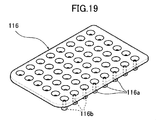
- FIG. 19 is a perspective view of the watering plate 116
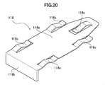
- FIG. 20 is a perspective view of the spring member 118.
- the outer cylinder 102 is a metal cylindrical member, and the base end 102a and the distal end opening 102b are open. Further, the base end portion side of the outer cylinder 102 is formed to have a substantially circular cross section, and constitutes a grip portion 106 of the shower head 100. On the other hand, the tip end side constitutes a thin water sprinkling portion 104 that is flatter than the gripping portion and has a wide, generally rectangular cross section. Between the base end side of the generally circular cross section and the tip end side of the generally rectangular cross section, the cross sectional shape is formed so as to smoothly transition from a circular shape to a flat rectangular shape.
- a plurality of water spray holes 102 c are formed on the wide side surface on the distal end side of the outer cylinder 102. As will be described later, the distal end opening 102b is closed by welding a metal member 102d after disposing a water passage member inside the outer cylinder 102.
- the connecting pipe 108 is a substantially cylindrical metal member.
- a substantially disc-shaped flange portion 108a is formed at the intermediate portion of the connecting pipe 108, and the outer periphery of the flange portion 108a is welded to the base end portion 102a of the outer tube 102, whereby the base end portion of the outer tube 102 is obtained.
- the open side is covered (FIG. 13).
- a male screw part 108 b is formed at the base end part of the connection pipe 108, and the shower hose 1 is coupled to the shower head 100 by screwing the socket 2 (FIG. 13) into the male screw part 108 b.
- a cylindrical water pipe connecting portion 108 c is formed on the distal end side of the connecting pipe 108, and the water pipe connecting portion 108 c is inserted into the proximal end portion of the water pipe 110, thereby connecting the connecting pipe 108 and the water pipe. 110 communicates.
- a groove 108d is formed on the outer periphery of the water pipe connecting portion 108c, and by arranging an O-ring in the groove 108d, water tightness between the connection pipe 108 and the water pipe 110 is ensured (FIG. 13). .
- the water conduit 110 is an elongated cylindrical member made of resin.
- the proximal end side of the water flow pipe 110 is formed in a substantially circular cross section, and the distal end side is formed in a substantially rectangular cross section.
- the connecting pipe 108 is inserted into the proximal end portion 110a of the water conduit 110, while the water conduit connecting portion 112a (FIG. 17) of the water sprinkling chamber forming member 112 is inserted into the distal end portion 110b of the water conduit 110. And coupled (FIG. 13).
- the water sprinkling chamber forming member 112 is a generally thin box-shaped member, and by attaching a presser lid 114, a watering chamber having a substantially rectangular parallelepiped shape is formed inside.
- a water passage connecting portion 112a is formed on the proximal end side of the water sprinkling chamber forming member 112, and a water sprinkling chamber portion 112b is formed on the distal end side.
- the connection part 112c which connects these between the water pipe connection part 112a and the sprinkling chamber part 112b is formed.
- the water pipe connecting portion 112 a is configured in a cylindrical shape having a substantially rectangular cross section, and is communicated with the water pipe 110 by being inserted into the distal end portion 110 b of the water pipe 110. Further, a groove 112d is formed on the outer periphery of the water pipe connecting portion 112a, and a water tightness between the water pipe connecting portion 112a and the water pipe 110 is ensured by arranging a packing in the groove 112d ( FIG. 13).
- the connecting portion 112c is a flow path that connects the water pipe connecting portion 112a and the water sprinkling chamber portion 112b, and is formed so as to spread in a tapered shape from the water pipe connecting portion 112a toward the water sprinkling chamber portion 112b.
- the water sprinkling chamber 112b is formed in a substantially rectangular parallelepiped shape, and a plurality of circular holes 112e are provided on the bottom surface. Each circular hole 112e is positioned so as to be aligned with each watering hole 102c provided in the outer cylinder 102 when the watering chamber forming member 112 is disposed in the outer cylinder 102. Moreover, the open ceiling surface of the connection part 112c and the water sprinkling chamber part 112b is comprised so that it may be closed by the pressing lid 114 (FIG. 18).
- the presser lid 114 is a plate-like member having an edge, and is configured to close the open portion of the sprinkling chamber forming member 112.
- the pressing lid 114 has a flat plate-like portion 114a and an edge portion 114b formed on the peripheral edge of the plate-like portion 114a.
- the edge 114b fits into the open part of the water sprinkling chamber forming member 112, so that the plate-like part 114a covers the open part.
- the plate-like portion 114a is provided with a plurality of pins 114c toward the inside of the watering chamber.
- the pins 114c are arranged in a grid pattern on the plate-like portion 114a, and their tips are configured to abut against the back surface of the watering plate 116 disposed inside the watering chamber (FIG. 13). Further, the columns and rows of the arranged pins 114c are arranged so as to be positioned between the columns and rows of the circular holes 112e (each watering hole 102c) arranged in a lattice pattern. Accordingly, the water spray plate 116 is pressed by the pins 114c without the pins 114c blocking the water spray holes 102c.
- a groove 114d is formed on the outer periphery of the edge portion 114b.
- the watering plate 116 which is the watering direction regulating means is a plate-like member made of silicon rubber which is an elastic body.
- a plurality of watering nipples 116a arranged in a grid pattern are provided on this watering plate 116.
- Each water spray nipple 116 a is substantially cylindrical and is positioned so as to be aligned with each circular hole 112 e provided in the water spray chamber forming member 112 and each water spray hole 102 c provided in the outer cylinder 102.
- each watering nipple 116a passes through the circular hole 112e of the watering chamber forming member 112 and the watering hole 102c of the outer tube 102, and the outer cylinder. Projects to the outside of 102. Further, water spray nozzle holes 116b are provided on the central axis of each water spray nipple 116a. Hot water supplied into the watering chamber is sprinkled through these watering nozzle holes 116b. The direction in which the hot water is sprayed is generally defined by the hot water passing through each of the water spray nozzle holes 116b, so that the water spray plate 116 functions as a water spray direction defining means.
- the tip of each pin 114 c provided on the presser lid 114 is connected to the rear surface of the water spray plate 116. Press the side (the side where the watering nipple 116a is not provided). Thereby, the watering plate 116 is pressed against the bottom surface of the watering chamber forming member 112 and is brought into close contact therewith.
- the spring member 118 is made of a metal thin plate, and acts as a plate spring by bending a part of the metal plate.
- the spring member 118 includes a flat plate portion 118a and a bent portion 118b obtained by bending the tip of the flat plate portion 118a.
- the flat plate portion 118a is configured to be placed on the presser lid 114, and is formed in substantially the same shape as the presser lid 114. Further, the flat plate portion 118a is provided with notches, and five rectangular leaf springs 118c are formed.
- Each leaf spring 118c is a cantilever whose one end is connected to the flat plate portion 118a, and is bent into a " ⁇ " shape at two locations.
- the spring member 118 is disposed on the back side of the presser lid 114, and the bent corner of each leaf spring 118c abuts against the inner wall surface on the back side of the outer cylinder 102 to urge the watering chamber from the outside ( FIG. 13).
- the presser lid 114, the water spray chamber forming member 112 and the water spray plate 116 attached thereto are pressed against the inner wall surface on the front surface side of the outer cylinder 102.
- the water spray plate 116 is pressed against the inner wall surface of the outer cylinder 102 by the spring member 118 through the pressing lid 114, so that each water spray nipple 116a of the water spray plate 116 is reliably projected from each water spray hole 102c.
- FIG. 21 is a diagram illustrating a manufacturing procedure of the shower head 100.
- a stainless steel flat plate is plastically deformed by roll forming and processed into a cylindrical shape.
- step S2 the butted surfaces of the stainless plate plastically deformed into a cylindrical shape are welded and joined. As a result, a stainless steel tube which is a metal tube is formed.
- step S3 a stainless steel plate is welded to the tip of the formed raw tube, and the front end of the raw tube is sealed. Thereby, an occlusion tube is formed.
- the above steps S1 to S3 are referred to as a metal tube forming step.
- step S4 the weld trace of the closed tube is removed by polishing.
- step S5 the closed tube is bent to form a bent tube.
- step S6 the distal end portion of the bending tube is deformed into a flat shape by pressing.
- step S7 the bent pipe deformed into a flat shape is bulged. That is, the bent tube deformed into a flat shape is loaded into a bulge processing mold and the mold is tightened. Further, a filling material such as a liquid is injected into the bending tube, and the bending tube is expanded and plastically deformed by applying a high pressure of about 200 MPa at the maximum to the filling material. Thus, the bulged bent tube is formed into a bulged product having substantially the same shape as the mold cavity.
- the above steps S5 to S7 are referred to as an outer shape forming process.
- step S8 piercing is performed in a state where high pressure is applied to the filling inside the mold immediately after plastic deformation by bulge processing.
- the sprinkling holes 102c are formed by inserting piercing pins from the outside of the bulge processed product. Thereby, a sprinkling hole processed product is obtained.
- step S8 is referred to as a sprinkling hole forming step.
- step S9 the closed portion at the tip of the sprinkling hole processed product is cut and the tip is opened. Thereby, a pre-processed product is obtained.
- step S9 is referred to as a cutting process.
- step S10 surface finishing is performed by polishing the surface of the pre-processed product. Thereby, the outer cylinder 102 in a state where the distal end portion is opened is formed.
- a water passage member such as the water sprinkling chamber forming member 112 is disposed inside the outer cylinder 102 in a state where the tip is opened. That is, after the watering plate 116 is disposed in the watering chamber forming member 112, the pressing lid 114 is attached to the open portion of the watering chamber forming member 112 via the packing 120 to form an assembly. This assembly is inserted from the opening at the tip of the outer cylinder 102 and placed.
- each watering nipple 116a of the water spray plate 116 is aligned with each watering hole 102c of the outer cylinder 102, and each watering nipple 116a protrudes from each watering hole 102c.
- the spring member 118 is inserted between the pressing lid 114 and the inner wall surface of the outer cylinder 102.
- the pressing lid 114 is pressed by the urging force of the leaf spring 118 c, and the water spray chamber forming member 112 is pressed against the inner wall surface of the outer cylinder 102 opposite to the spring member 118.
- the assembly is accurately positioned and fixed inside the outer cylinder 102.
- step S11 is referred to as an arrangement step.
- step S12 a metal member is laser welded to the opening at the tip of the outer cylinder 102 to close the opening. Further, the flange portion 108a of the connecting pipe 108 is welded to the base end portion 102a of the outer cylinder 102, and the shower head 100 is completed.
- YAG laser welding or fiber laser welding is used as laser welding.
- step S12 is referred to as a welding process.
- the shower head 100 of this embodiment is used by connecting the shower hose 1 via the socket 2. Hot water supplied from the shower hose 1 flows into the water pipe 110 through the connection pipe 108. The hot water that has flowed into the water flow pipe 110 passes through the water flow pipe connecting portion 112a of the water sprinkling chamber forming member 112 and flows into a water sprinkling chamber that is a space formed between the water sprinkling chamber forming member 112 and the presser lid 114. Hot water flowing into the watering chamber is sprinkled through a plurality of watering nozzle holes 116 b provided in the watering plate 116.
- the direction of the hot water sprayed is defined by the water spray nozzle hole 116b. Further, since the water spray plate 116 made of silicon rubber is pressed against the bottom surface of the water sprinkling chamber forming member 112 by a plurality of pins 114c provided on the presser lid 114, the hot water in the sprinkling chamber is connected to the sprinkling plate 116 and the sprinkling chamber. It is possible to prevent leakage from the gap between the water spray nipple 116a and the circular hole 112e by entering between the bottom surfaces of the forming member 112.
- each water spray nipple 116a of the water spray plate 116 is formed of silicon rubber that is an elastic body, so that the scale adheres to the water spray nozzle hole 116b and the water spray nozzle hole.
- the scale can be peeled by picking each watering nipple 116a and elastically deforming it. Since such a watering plate 116 is provided as a watering direction defining means, the watering part 104 of the shower head 100 can be formed thin and compact.
- the watering plate 116 is pressed against the inner wall surface of the outer cylinder 102 by the spring member 118 together with the watering chamber forming member 112 and the pressing lid 114, so that the watering nipple 116 a is disposed. It can project reliably from the outer cylinder.
- the spring member 118 urges the water passage member such as the presser lid 114 from the outside of the sprinkling chamber, so the time during which the spring member 118 is in contact with hot water is short.
- the spring member 118 can be prevented from being corroded by hot water.
- the shower head 100 of this embodiment since the external appearance of the shower head 100 is unified with a metal, the shower head 100 excellent in design property can be comprised.
- the distal end opening portion 102b of the outer cylinder is closed by laser welding the metal member 102d, so that the joint between the metal member 102d and the metal member 102d is conspicuous. Therefore, the beauty of the shower head 100 can be improved. Further, it is possible to prevent dirt from adhering to the joint portion.
- the appearance of the shower head 100 is configured by laser welding the metal member 102d to the tip opening 102b of the outer cylinder 102 that is a metal tube. Therefore, the shower head 100 can be manufactured which has a uniform external appearance with metal and has an excellent aesthetic appearance that is not conspicuous.
- a water passage member such as the water sprinkling chamber forming member 112 is arranged inside the outer cylinder 102 formed in a predetermined shape, the front end opening 102b of the outer cylinder 102 into which the water passage member is inserted is closed. For this reason, the shape of the water passage member is not easily restricted by the shape of the outer cylinder 102, and the degree of freedom of design of the manufactured shower head 100 can be increased.
- the outer tube 102 that is a metal tube is formed by bulge processing, so that the entire showerhead 100 with many curved surfaces can be easily formed of metal. it can.
- the present invention has been described above. However, the present invention is not limited to these descriptions.
- the metal plate forming the outer cylinder has been described by exemplifying SUS304, other metal materials can be appropriately used as long as they have good appearance and durability against water.
- the structure for fixing the water passage member and the water spray member to the outer cylinder has been described based on the third embodiment, its modification, and the fourth embodiment.
- the water passage member and the water spray member are inserted into the outer cylinder. In this state, it is also possible to adopt a structure in which the water passage member and the water spray member are fixed so as not to move with respect to the outer cylinder by crimping the end of the outer cylinder.
- Sprinkling hole 84 Connecting tool 9 ... shower Head 91 ... Outer cylinder 91a ... Sprinkling hole 91b ... Sprinkling part 911 ... Grasping part 92 ... Water passage member 92a ... Inlet 92b ... Outlet 93 ... Packing 94 ... Fixing base 95 ... Connecting tool 100 ... shower head 102 ... Outer cylinder 102a ... Base end part 102b ... Tip opening part 102c ... Sprinkling hole 102d ... Metal member 104 ... Sprinkling part 106 ... Grasping part 108 ... Connecting pipe 108a ... Flange part 1 8b ... male screw part 108c ... water pipe connecting part 108d ...
- groove 110 ... water pipe 110a ... base end part 110b ... tip part 112 ... sprinkling chamber forming member 112a ... water pipe connecting part 112b ... sprinkling chamber part 112c ... connecting part 112d ... groove 112e ... Circular hole 114 ... Holding lid 114a ... Plate-like portion 114b ... Edge 114c ... Pin 114d ... Groove 116 ... Sprinkling plate (sprinkling direction regulating means) 116a ... Watering nipple 116b ... Watering nozzle hole 118 ... Spring member 118a ... Flat plate portion 118b ... Bending portion 118c ... Plate spring 120 ... Packing
Landscapes
- Engineering & Computer Science (AREA)
- Physics & Mathematics (AREA)
- Optics & Photonics (AREA)
- Mechanical Engineering (AREA)
- Health & Medical Sciences (AREA)
- Life Sciences & Earth Sciences (AREA)
- Hydrology & Water Resources (AREA)
- Public Health (AREA)
- Water Supply & Treatment (AREA)
- Plasma & Fusion (AREA)
- Fluid Mechanics (AREA)
- Nozzles (AREA)
- Bathtubs, Showers, And Their Attachments (AREA)
Abstract
Description
また、シャワーヘッドの把持部にのみ通水路部材が内蔵されているので、シャワーヘッドの重心を把持部側に位置させることも可能である。この場合には、シャワーヘッドを手に持ったときの安定性を高めることができる。
図1は本発明の第一の実施形態にかかるシャワーヘッドを示す斜視図である。
シャワー装置は、湯水混合水栓(図示せず)のシャワー側吐出口に連結されたシャワーホース1にソケット2を介してシャワーヘッド3が連結された構成であり、シャワーヘッド3を手で持って使用することができるものである。
これにより、外筒31は、0.5mm~1mm程度の薄肉に形成することができ、従来のシャワーヘッドよりも軽量化されたものとなる。そのため、材料費や製造費、輸送費を削減することができ、従来よりも低コストで金属製のシャワーヘッドを提供することができる。また、シャワーヘッドの軽量化により、輸送時のCO2排出量を削減することができる。
また、この外筒31は、SUS304等の光沢のある金属で形成することによって、真鍮のように表面にクロムめっき等の装飾めっきを施さなくても、良質な、金属製のシャワーヘッドを作製することができる。そのため、ニッケルクロムめっきを施してメタル調の外観にした従来のシャワーヘッドのようにめっきが剥がれる恐れが無い。
また、外筒31の端面は、散水部材33で覆われることなく、外部に露出している。すなわち、薄肉の金属の端面が露出しており、従来の装飾めっきを施したシャワーヘッドのように、めっき剥がれ防止のために、メタル調のシャワーヘッドの端面を樹脂部材で覆い隠すような端部処理を行っていない。よって、側面の全体を金属とした、スッキリしたデザインのシャワーヘッド3を得ることができる。
シャワーヘッドの内部には、前述したとおり、基端部側の開放端から外筒31内に挿入された通水路部材32が設けられている。この通水路部材32は、外筒31との間に所定寸法の隙間を設けて外筒31に内蔵されている。前述したように、外筒31は、0.5mm~1mm程度の薄肉金属なので、熱を伝えやすい性質を有しているが、通水路部材32との間に隙間を設けることにより、その隙間が断熱性を持つ空気層341となるので、通水路部材32を流れる湯水の熱は外筒31に伝わりにくい。また、シャワーヘッド3を手に持つことで、外筒31が体温で加熱されるが、その熱も通水路部材32に伝わりにくい。これにより、シャワーヘッド3を手に持っても湯水の温度を感じにくくなると共に、人の体温で湯水の温度が変化しにくくなる。
この変形例では、図2に示した断熱手段としての空気層341に代えて、外筒31と通水路部材32の間の隙間に、熱伝導率の低い断熱材342を挿入している。断熱材342としては、発泡ポリウレタンなどの熱伝導率が低く、自己接着性の高い材料が好適である。
また、他の変形例として、図示はしないが、樹脂製の通水路部材32の厚みを増加することでも通水路部材32自体に断熱性を付与することができる。
いずれの変形例の場合でも、第一の実施形態と同様の効果を得ることができる。
図4は第二の実施形態にかかるシャワーヘッドを示す斜視図である。
シャワー装置は、湯水混合水栓(図示せず)のシャワー側吐出口に連結されたシャワーホース1にソケット2を介してシャワーヘッド4が連結された構成であり、シャワーヘッド4を手で持って使用することができるものである。
これにより、外筒41は、0.5mm~1mm程度の薄肉に形成することができ、従来のシャワーヘッドよりも軽量化される。そのため、材料費や製造費、輸送費を削減することができ、従来よりも低コストで金属製のシャワーヘッドを提供することができる。また、シャワーヘッドの軽量化により、輸送時のCO2排出量を削減することができる。
また、シャワーホース1に接続される部分を除いたシャワーヘッド4の全体が、SUS304等の光沢のある金属で形成された継ぎ目の無い外筒41で覆われることによって、真鍮のように表面にクロムめっき等の装飾めっきを施さなくても、良質な、金属製のシャワーヘッドを作製することができる。そのため、ニッケルクロムめっきを施してメタル調の外観にした従来のシャワーヘッドのようにめっきが剥がれる恐れが無い。また、基端部を除けば、シャワーヘッド4の表面には、上記の第一の実施形態に見られる外筒31の開口部31aに散水部材33が装着されることによって生ずる樹脂製部材と本体の金属部材との継ぎ目が表れないので、継ぎ目に汚れがこびりつくこともなく、清潔感にあふれるシャワーヘッドとなる。
シャワーヘッドの内部には、前述したとおり、基端部側の開放端から外筒41内に挿入された通水路部材42が設けられている。そして、通水路部材42の先端はパッキン43を介して外筒41に圧入されている。このため、通水路部材42の出水口42bから出水された湯水は、外筒41と通水路部材42の間の隙間に入り込まない。
なお、外筒41と通水路部材42の間には、第一の実施形態と同様の断熱手段(空気層341)が形成されているから、シャワーヘッド4を手に持っても湯水の温度を感じにくくなると共に、人の体温で湯水の温度が変化しにくくなる。
これにより、シャワーヘッド4の外筒41は、基端部側のみに樹脂成形品である通水路部材42が設けられるので、シャワーヘッド4の重心が、把持部411に位置するので、シャワーヘッド4を手持ちしたときの安定感が従来のシャワーヘッドよりも高まる。
図6は散水部の構造を説明する部分拡大断面図である。
図6に示すように、通水路部材42から出水した湯水が、散水孔41aから散水される。本実施形態では、0.5mm~1mm程度の薄肉の金属板で形成される外筒41の一部、すわなち散水部41bの部分だけ肉厚を厚くしておく。これにより、散水方向を安定させることが可能となる。
しかし、0.5mm~1mm程度の薄肉の金属板に散水孔を開設する場合、外筒41の先端部の形状や、湯水の流量によっては、複数の散水孔41aから吐水された水をシャワー状(扇状)に散水するのは困難となる場合がある。
図7は第二の実施形態にかかるシャワーヘッドの変形例における散水部の構造を説明する部分拡大断面図である。
この変形例では、散水部41bは、通水路部材51を外筒41の先端部にまで配置し、外筒41の散水孔ピッチに合わせて矩形形状の開口部52aを形成して、通水路部材51から水が流れ出す方向を規定する方向規制部52としている。この方向規制部52は、通水路部材51の基端部(シャワーホース側端部)から流れてきた水が、進行方向に向かおうとする力を低減するので、図6に示した散水部よりも、散水孔41aの中心軸方向に向けて散水させることが可能である。
この他の変形例では、散水部41bは、外筒41の散水部41bの内部に散水板61を内蔵させている。この散水板61は、外筒41に形成された複数の散水孔ピッチに合わせて、外筒41の肉厚よりも大きな長さに形成された通水孔61aを、散水方向に向けて形成したものであり、外筒41の散水孔41aが形成された側の内面に水密状に取り付けられている。通水路部材42の出水口42bから出水された湯水は、外筒41の内部を通過して散水板61の通水孔61aを通過して散水孔41aから散水される。
図9は第三の実施形態にかかるシャワーヘッドの断面模式図、図10はシャワーヘッドの先端部を示す斜視図であり(a)は従来のプラめっきによるシャワーヘッドの先端部を示した図、(b)は図9に示すシャワーヘッドの先端部を示した図である。
これにより、外筒71は、0.5mm~1mm程度の薄肉に形成することができ、従来のシャワーヘッドよりも軽量化されたものとなる。そのため、材料費や製造費、輸送費を削減することができ、従来よりも低コストで金属製のシャワーヘッドを提供することができる。また、シャワーヘッドの軽量化により、輸送時のCO2排出量を削減することができる。
また、この外筒71は、SUS304等の光沢のある金属で形成することによって、真鍮のように表面にクロムめっき等の装飾めっきを施さなくても、良質な、金属製のシャワーヘッドを作製することができる。そのため、ニッケルクロムめっきを施してメタル調の外観にした従来のシャワーヘッドのようにめっきが剥がれる恐れが無い。
なお、通水路部材72の入水口72aには、ソケット2を介してシャワーホース1が接続される。
従来の装飾めっきを施したシャワーヘッドでは、図10(a)に示すように、めっき部分の端部に衝撃を与えないように、メタル調のシャワーヘッドPの端面を樹脂部材Qで覆い隠し、これによりめっき剥がれを防止していた。しかし、本実施形態では、図10(b)に示すように、外筒71の端面を樹脂部材(通水路部材72、散水部材73)で覆わずに、外部に露出させている。そのため、シャワーヘッドの側面には、散水孔が形成された部位を除いて、通水路部材72と散水部材73が露出しないことから、シャワーヘッドの端部に樹脂のラインが表れない。よって、従来よりもシャワーヘッドの意匠性を向上させることができる。
この変形例のシャワーヘッドは、シャワーヘッド8の外郭を構成する外筒81と、外筒81の基端部に装着されて、シャワーホース1から供給される湯水を外筒81内に導入する樹脂製の通水路部材82と、外筒81の先端部に装着されて、湯水をシャワー状に散水する複数の散水孔83bを有する散水部としての散水部材83とで構成されている。
外筒81の基端部側の開口部81aと先端部側の開口部81bは、外筒81の肉厚が端部ほど次第に薄くなるようにバルジ成形時に加工されており、外筒81の内径が端部ほど大きくなるようにテーパ状になっている。
なお、通水路部材82の入水口82aには、ソケット2を介してシャワーホース1が接続される。
本実施形態のシャワーヘッドは、シャワーヘッド9の外郭を成すと共に先端部側の側面に複数の散水孔91aを有する散水部91bが形成された外筒91と、シャワーホース1から供給される湯水を外筒91内に導入する通水路部材92とで構成されている。
また、シャワーホース1に接続される部分を除いたシャワーヘッド9の全体が、SUS304等の光沢のある金属で形成された継ぎ目の無い外筒91で覆われることによって、真鍮のように表面にクロムめっき等の装飾めっきを施さなくても、良質な、金属製のシャワーヘッドを作製することができる。そのため、ニッケルクロムめっきを施してメタル調の外観にした従来のシャワーヘッドのようにめっきが剥がれる恐れが無い。また、基端部を除けば、シャワーヘッド9の表面には、部材と部材の継ぎ目が表れないので、継ぎ目に汚れがこびりつくこともなく、清潔感にあふれるシャワーヘッドとなる。
この通水路部材92の先端はパッキン93を介して外筒91に圧入されている。このため、通水路部材92の出水口92bから出水された湯水は、外筒91と通水路部材92の間の隙間に入り込まない。
これにより、シャワーヘッド9の外筒91は、基端部側のみに樹脂成形品である通水路部材92が設けられるので、シャワーヘッド9の重心が、把持部911に位置するので、シャワーヘッド9を手持ちしたときの安定感が従来のシャワーヘッドよりも高まる。
図13は本実施形態によるシャワーヘッドの全断面図である。
図13に示すように、本実施形態のシャワーヘッド100は、ソケット2を介してシャワーホース1に接続して使用されるハンドシャワー用のシャワーヘッドである。このシャワーヘッド100の筐体を構成する外筒102は、金属板であるSUS304を塑性変形させることにより構成されると共に、その表面には装飾めっきは施されていない。また、シャワーヘッド100の先端部側には湯水を散水するための散水部104が設けられ、基端部側には、使用者が手指で把持するための把持部106が形成されている。
図14は外筒102の斜視図であり、図15は接続管108の斜視図であり、図16は通水管110の斜視図であり、図17は散水室形成部材112の斜視図であり、図18は押さえ蓋114の斜視図であり、図19は散水プレート116の斜視図であり、図20はばね部材118の斜視図である。
まず、図21のステップS1においては、ステンレス製の平板をロールフォーミング加工により塑性変形させ、筒状に加工する。
ステップS3においては、形成された素管の先端にステンレス板を溶接して、素管の先端を封止する。これにより、閉塞管が形成される。なお、本実施形態においては、以上のステップS1~S3を金属管形成工程という。
ステップS5においては、閉塞管を曲げ加工して、曲げ管を形成する。
さらに、ステップS6においては、曲げ管の先端部分をプレス加工により扁平状に変形させる。
ステップS10においては、プレ加工品の表面を研磨することにより、表面仕上げを行う。これにより、先端部が開放された状態の外筒102が形成される。
まず、本実施形態のシャワーヘッド100は、ソケット2を介してシャワーホース1を接続して使用される。シャワーホース1から供給された湯水は、接続管108を通って通水管110に流入する。通水管110に流入した湯水は、散水室形成部材112の通水管接続部112aを通って、散水室形成部材112と押さえ蓋114の間に構成された空間である散水室に流入する。散水室に流入した湯水は、散水プレート116に設けられた複数の散水ノズル孔116bを通って散水される。散水される湯水の方向は、散水ノズル孔116bにより規定される。また、シリコンゴム製の散水プレート116は、押さえ蓋114に設けられた複数のピン114cにより、散水室形成部材112の底面に押し付けられているので、散水室内の湯水が、散水プレート116と散水室形成部材112の底面の間に入り込み、散水ニップル116aと円形孔112eの間の隙間から洩れるのを防止することができる。また、湯水中の不純物が散水ノズル孔116bの内部でスケールとして付着し、散水ノズル孔116bが詰まった場合には、外筒102から突出している散水ニップル116aを手指で摘んで変形させることにより、スケールを除去する。
例えば、外筒を形成する金属板は、SUS304を例示して説明したが、見栄えがよく、水に対する耐久性があれば、他の金属材料を適宜用いることが可能である。
また、通水路部材および散水部材を外筒に固定する構造について、第三実施形態、その変形例、第四実施形態に基づいて説明したが、例えば、通水路部材や散水部材を外筒に挿入した状態で、外筒の端部をカシメることにより通水路部材や散水部材を外筒に対して動かぬように固定する構造を採用することも可能である。
2…ソケット
3…シャワーヘッド
31…外筒
31a…開口部
311…把持部
32…通水路部材
32a…入水口
32b…出水口
33…散水部材(散水部)
33a…導入口
33b…散水孔
341…空気層(断熱手段)
342…断熱材(断熱手段)
4…シャワーヘッド
41…外筒
41a…散水孔
41b…散水部
411…把持部
42…通水路部材
42a…入水口
42b…出水口
43…パッキン
51…通水路部材
52…方向規制部(散水方向規定手段)
52a…開口部
61…散水板(散水方向規定手段)
61a…通水孔
7…シャワーヘッド
71…外筒
71a,71b…開口部
711…把持部
72…通水路部材
72a…入水口
72b…出水口
72c…フランジ
73…散水部材
73b…散水孔
74…連結具
75…固定用ベース
76…連結具
8…シャワーヘッド
81…外筒
81a,81b…開口部
82…通水路部材
82a,82b…入水口
83…散水部材
83b…散水孔
84…連結具
9…シャワーヘッド
91…外筒
91a…散水孔
91b…散水部
911…把持部
92…通水路部材
92a…入水口
92b…出水口
93…パッキン
94…固定用ベース
95…連結具
100…シャワーヘッド
102…外筒
102a…基端部
102b…先端開口部
102c…散水孔
102d…金属製の部材
104…散水部
106…把持部
108…接続管
108a…フランジ部
108b…雄ねじ部
108c…通水管接続部
108d…溝
110…通水管
110a…基端部
110b…先端部
112…散水室形成部材
112a…通水管接続部
112b…散水室部
112c…接続部
112d…溝
112e…円形孔
114…押さえ蓋
114a…板状部
114b…縁部
114c…ピン
114d…溝
116…散水プレート(散水方向規定手段)
116a…散水ニップル
116b…散水ノズル孔
118…ばね部材
118a…平板部
118b…折曲部
118c…板ばね
120…パッキン
Claims (16)
- 金属板を塑性変形させて、少なくとも基端部側の端部を開放させた筒状に形成されて、前記金属板の表面に装飾めっきを施していない外筒と、
前記基端部側の開放端から前記外筒内に挿入されて、シャワーホースから供給された湯水を前記外筒内に供給する通水路部材と、を備え、
前記外筒の基端部側に、前記外筒を手に持つための把持部を設けると共に、
前記外筒の先端部側に、前記通水路部材から供給された湯水を散水するための複数の散水孔が形成された散水部を設けたことを特徴とするシャワーヘッド。 - 前記散水部は、前記外筒の先端部側の側面に前記散水孔を形成することにより構成されていることを特徴とする請求項1記載のシャワーヘッド。
- 前記散水部が設けられた先端部は、前記把持部よりも扁平且つ幅広の薄体状に形成されることを特徴とする請求項2記載のシャワーヘッド。
- 前記散水部が設けられた先端部は、前記通水路部材から供給された湯水が、前記外筒の内面を直接流れて、前記散水孔に供給されるように構成されたことを特徴とする請求項3記載のシャワーヘッド。
- 前記散水部は、前記通水路部材を通って供給された湯水を、前記複数の散水孔から所定の角度に向けて散水させるための散水方向規定手段を備えたことを特徴とする請求項2~4のいずれか1項に記載のシャワーヘッド。
- 前記散水方向規定手段は、散水ノズル孔が形成された複数の散水ニップルを備えた、弾性体製の散水プレートから構成され、前記各散水ニップルは、前記外筒に形成された前記各散水孔から突出されている請求項5記載のシャワーヘッド。
- さらに、前記散水プレートを前記外筒の内壁面に押し付けるばね部材を有し、前記散水プレートが前記外筒の内壁面に押し付けられることにより、前記各散水ニップルは前記各散水孔から突出される請求項6記載のシャワーヘッド。
- 前記散水プレートは前記通水路部材に取り付けられ、前記通水路部材が前記ばね部材により前記通水路部材の外側から付勢されることにより、前記散水プレートが前記外筒の内壁面に押し付けられる請求項7記載のシャワーヘッド。
- 前記外筒は、その先端の先端開口部から前記散水プレートを挿入し、配置した後、前記先端開口部を金属製の部材で閉鎖することにより構成されている請求項6記載のシャワーヘッド。
- 前記先端開口部は、前記金属製の部材をレーザー溶接することにより閉鎖される請求項9記載のシャワーヘッド。
- 前記散水孔を形成した樹脂製の散水部材を備え、
前記外筒の先端部側に形成された開口部に前記散水部材を装着して前記散水部としたことを特徴とする請求項1記載のシャワーヘッド。 - 前記金属板と前記通水路部材との間に断熱手段を設け、
前記断熱手段が設けられた範囲内に前記把持部を設けたことを特徴とする請求項1~11のいずれか1項に記載のシャワーヘッド。 - 前記通水路部材を前記金属板よりも熱伝導率の小さな樹脂で形成したことを特徴とする請求項1~12のいずれか1項に記載のシャワーヘッド。
- 前記通水路部材は樹脂で成形された樹脂成型部品であり、前記外筒の内壁面には、前記外筒の内部に配置された前記通水路部材が前記外筒の端部から突出しないように、前記通水路部材を前記外筒に固定するための固定手段が設けられている請求項1~13のいずれか1項に記載のシャワーヘッド。
- シャワーヘッドを製造する方法であって、
金属製の管を塑性変形させることにより、前記金属製の管を所定の形状に形成する外郭形状形成工程と、
所定の形状に形成された前記金属製の管に複数の散水孔を形成する散水孔形成工程と、
前記散水孔が形成された前記金属製の管の内部に、前記金属製の管の開口部を通して通水路部材を配置する配置工程と、
金属製の部材を前記開口部にレーザー溶接することにより、前記開口部を閉鎖する溶接工程と、
を有することを特徴とするシャワーヘッドの製造方法。 - 前記外郭形状形成工程が、
前記金属製の管を、バルジ加工用の金型内に配置する工程と、
前記金型内に配置された前記金属製の管の内部に充填物を充填する工程と、
前記充填物に圧力を加えることにより前記金属製の管を拡張させ、前記金属製の管を前記金型の形状に塑性変形させるバルジ加工を行う工程と、
を有する請求項15記載のシャワーヘッドの製造方法。
Priority Applications (4)
| Application Number | Priority Date | Filing Date | Title |
|---|---|---|---|
| CN201180032026.9A CN102958413B (zh) | 2010-07-15 | 2011-07-14 | 淋浴喷头以及淋浴喷头的制造方法 |
| JP2012524591A JP5818024B2 (ja) | 2010-07-15 | 2011-07-14 | シャワーヘッド及びシャワーヘッドの製造方法 |
| US13/739,966 US20130126642A1 (en) | 2010-07-15 | 2013-01-11 | Showerhead and showerhead manufacturing method |
| US15/429,967 US10195654B2 (en) | 2010-07-15 | 2017-02-10 | Showerhead and showerhead manufacturing method |
Applications Claiming Priority (2)
| Application Number | Priority Date | Filing Date | Title |
|---|---|---|---|
| JP2010160634 | 2010-07-15 | ||
| JP2010-160634 | 2010-07-15 |
Related Child Applications (1)
| Application Number | Title | Priority Date | Filing Date |
|---|---|---|---|
| US13/739,966 Continuation US20130126642A1 (en) | 2010-07-15 | 2013-01-11 | Showerhead and showerhead manufacturing method |
Publications (1)
| Publication Number | Publication Date |
|---|---|
| WO2012008535A1 true WO2012008535A1 (ja) | 2012-01-19 |
Family
ID=45469530
Family Applications (1)
| Application Number | Title | Priority Date | Filing Date |
|---|---|---|---|
| PCT/JP2011/066123 Ceased WO2012008535A1 (ja) | 2010-07-15 | 2011-07-14 | シャワーヘッド及びシャワーヘッドの製造方法 |
Country Status (4)
| Country | Link |
|---|---|
| US (2) | US20130126642A1 (ja) |
| JP (1) | JP5818024B2 (ja) |
| CN (1) | CN102958413B (ja) |
| WO (1) | WO2012008535A1 (ja) |
Cited By (3)
| Publication number | Priority date | Publication date | Assignee | Title |
|---|---|---|---|---|
| JP2014008328A (ja) * | 2012-07-02 | 2014-01-20 | Toto Ltd | シャワーヘッド |
| JP2018187181A (ja) * | 2017-05-10 | 2018-11-29 | 伊藤産業株式会社 | シャワーヘッド |
| JP2021178102A (ja) * | 2020-05-15 | 2021-11-18 | タカラスタンダード株式会社 | 浴槽蓋支持具 |
Families Citing this family (19)
| Publication number | Priority date | Publication date | Assignee | Title |
|---|---|---|---|---|
| CN104625595B (zh) * | 2013-11-14 | 2017-03-01 | 陈重荣 | 淋浴装置及其制造方法 |
| JP6241815B2 (ja) * | 2015-12-15 | 2017-12-06 | Toto株式会社 | 吐水装置 |
| USD793529S1 (en) * | 2016-01-07 | 2017-08-01 | Delta Faucet Company | Handshower |
| USD787634S1 (en) * | 2016-01-11 | 2017-05-23 | Delta Faucet Company | Handshower |
| GB2553110A (en) * | 2016-08-22 | 2018-02-28 | Kelda Showers Ltd | Shower head producing a suspension of water droplets in air |
| USD960302S1 (en) | 2017-06-28 | 2022-08-09 | Phoenix Industries Pty Ltd | Shower head |
| USD972922S1 (en) | 2019-02-22 | 2022-12-20 | Phoenix Industries Pty Ltd | Hand shower bracket |
| USD939046S1 (en) * | 2019-02-22 | 2021-12-21 | Phoenix Industries Pty Ltd | Hand shower |
| USD954900S1 (en) | 2019-02-22 | 2022-06-14 | Phoenix Industries Pty Ltd | Rail shower |
| USD943709S1 (en) | 2019-02-22 | 2022-02-15 | Phoenix Industries Pty Ltd | Twin showers |
| USD942599S1 (en) | 2019-02-22 | 2022-02-01 | Phoenix Industries Pty Ltd | Hand shower bracket |
| USD939664S1 (en) | 2019-02-22 | 2021-12-28 | Phoenix Industries Pty Ltd | Hand shower |
| USD939047S1 (en) | 2019-02-22 | 2021-12-21 | Phoenix Industries Pty Ltd | Rail shower |
| JP1646807S (ja) * | 2019-03-28 | 2019-12-02 | ||
| USD957574S1 (en) * | 2020-06-11 | 2022-07-12 | Delta Faucet Company | Handshower |
| USD957570S1 (en) * | 2020-10-02 | 2022-07-12 | Kohler Co. | Handshower |
| CN115254471B (zh) * | 2021-08-16 | 2024-04-02 | 箭牌家居集团股份有限公司 | 一种出水切换装置及花洒 |
| IT202300023283A1 (it) | 2023-11-06 | 2025-05-06 | Steam Srl | “doccetta con doppio tubo in acciaio inox” |
| USD1118825S1 (en) * | 2024-12-19 | 2026-03-17 | Xiamen Prime Shower Co., Ltd. | Hand shower head |
Citations (8)
| Publication number | Priority date | Publication date | Assignee | Title |
|---|---|---|---|---|
| JPH09502650A (ja) * | 1993-09-16 | 1997-03-18 | ノルヴェク・アクティーゼルスカブ | シャワーヘッド |
| JPH09280403A (ja) * | 1996-04-11 | 1997-10-31 | Sanei Suisen Seisakusho:Kk | 湯水混合水栓 |
| JP2001288793A (ja) * | 2000-04-06 | 2001-10-19 | Takayasu Okubo | 給水栓取付け形塩素除去器 |
| JP2002320565A (ja) * | 2001-04-26 | 2002-11-05 | Mym Corp | シャワーヘッドとホースの接続構造 |
| JP2003181335A (ja) * | 2001-10-09 | 2003-07-02 | Cyber Techno:Kk | 霧状液体噴射装置および霧状液体噴射方法 |
| JP2007130615A (ja) * | 2005-11-08 | 2007-05-31 | Takayasu Okubo | シャワーヘッド |
| JP2007312829A (ja) * | 2006-05-23 | 2007-12-06 | Kvk Corp | シャワーヘッドのカバーの固定構造 |
| JP2008012413A (ja) * | 2006-07-04 | 2008-01-24 | Toto Ltd | シャワーヘッド |
Family Cites Families (10)
| Publication number | Priority date | Publication date | Assignee | Title |
|---|---|---|---|---|
| US1665744A (en) * | 1926-11-15 | 1928-04-10 | Justus P Seeburg | Face-spraying device |
| US1906991A (en) * | 1931-03-24 | 1933-05-02 | Joseph J Mcternan | Water sprinkler |
| US4600153A (en) | 1984-05-11 | 1986-07-15 | Stone Ronald K | Cleaning tool |
| US5600153A (en) * | 1994-10-07 | 1997-02-04 | Micron Technology, Inc. | Conductive polysilicon lines and thin film transistors |
| IT1293134B1 (it) * | 1997-05-05 | 1999-02-12 | Gevipi Ag | Doccetta alimentata da tubazione flessibile, con commutazione della modalita' di erogazione. |
| US6775865B1 (en) * | 2003-07-31 | 2004-08-17 | Globe Union Industrial Corp. | Shower unit with swivel spray arms |
| US7415991B2 (en) * | 2005-12-20 | 2008-08-26 | Masco Corporation Of Indiana | Faucet spout with water isolating couplings |
| JP3845868B1 (ja) * | 2006-03-29 | 2006-11-15 | 東陶機器株式会社 | 吐水装置 |
| US8430345B2 (en) * | 2008-02-12 | 2013-04-30 | Kohler Co. | Swivel spout assembly |
| US8376248B2 (en) * | 2008-11-25 | 2013-02-19 | As Ip Holdco, L.L.C. | Faucet having pull-out spray handle |
-
2011
- 2011-07-14 JP JP2012524591A patent/JP5818024B2/ja active Active
- 2011-07-14 CN CN201180032026.9A patent/CN102958413B/zh active Active
- 2011-07-14 WO PCT/JP2011/066123 patent/WO2012008535A1/ja not_active Ceased
-
2013
- 2013-01-11 US US13/739,966 patent/US20130126642A1/en not_active Abandoned
-
2017
- 2017-02-10 US US15/429,967 patent/US10195654B2/en active Active
Patent Citations (8)
| Publication number | Priority date | Publication date | Assignee | Title |
|---|---|---|---|---|
| JPH09502650A (ja) * | 1993-09-16 | 1997-03-18 | ノルヴェク・アクティーゼルスカブ | シャワーヘッド |
| JPH09280403A (ja) * | 1996-04-11 | 1997-10-31 | Sanei Suisen Seisakusho:Kk | 湯水混合水栓 |
| JP2001288793A (ja) * | 2000-04-06 | 2001-10-19 | Takayasu Okubo | 給水栓取付け形塩素除去器 |
| JP2002320565A (ja) * | 2001-04-26 | 2002-11-05 | Mym Corp | シャワーヘッドとホースの接続構造 |
| JP2003181335A (ja) * | 2001-10-09 | 2003-07-02 | Cyber Techno:Kk | 霧状液体噴射装置および霧状液体噴射方法 |
| JP2007130615A (ja) * | 2005-11-08 | 2007-05-31 | Takayasu Okubo | シャワーヘッド |
| JP2007312829A (ja) * | 2006-05-23 | 2007-12-06 | Kvk Corp | シャワーヘッドのカバーの固定構造 |
| JP2008012413A (ja) * | 2006-07-04 | 2008-01-24 | Toto Ltd | シャワーヘッド |
Cited By (4)
| Publication number | Priority date | Publication date | Assignee | Title |
|---|---|---|---|---|
| JP2014008328A (ja) * | 2012-07-02 | 2014-01-20 | Toto Ltd | シャワーヘッド |
| JP2018187181A (ja) * | 2017-05-10 | 2018-11-29 | 伊藤産業株式会社 | シャワーヘッド |
| JP2021178102A (ja) * | 2020-05-15 | 2021-11-18 | タカラスタンダード株式会社 | 浴槽蓋支持具 |
| JP7451292B2 (ja) | 2020-05-15 | 2024-03-18 | タカラスタンダード株式会社 | 浴槽蓋支持具 |
Also Published As
| Publication number | Publication date |
|---|---|
| US20170151601A1 (en) | 2017-06-01 |
| US10195654B2 (en) | 2019-02-05 |
| JPWO2012008535A1 (ja) | 2013-09-09 |
| CN102958413B (zh) | 2016-05-25 |
| US20130126642A1 (en) | 2013-05-23 |
| JP5818024B2 (ja) | 2015-11-18 |
| CN102958413A (zh) | 2013-03-06 |
Similar Documents
| Publication | Publication Date | Title |
|---|---|---|
| JP5818024B2 (ja) | シャワーヘッド及びシャワーヘッドの製造方法 | |
| KR100963423B1 (ko) | 하이드로 포밍을 이용한 워터 파이프 제조 방법 | |
| US7644652B2 (en) | Device for foaming milk, comprising external suction equipment | |
| US5333650A (en) | Hose coupling with a stiffening sleeve | |
| USD570953S1 (en) | Nozzle sleeve of a nozzle assembly for cleaning heat exchanger tubes | |
| USD567900S1 (en) | Nozzle core of a nozzle assembly for cleaning heat exchanger tubes | |
| ZA200702197B (en) | A valve connector for medical lines | |
| KR101435716B1 (ko) | 이중관 제조장치 및 그 제조방법 | |
| EP1605107B1 (en) | Washing nozzle and toilet device using the same | |
| US7216414B2 (en) | Method of attaching metal and plastic parts of an implement handle | |
| KR200491186Y1 (ko) | 수전금구의 공급수 배출관 조립체 | |
| JP5365993B2 (ja) | シャワーヘッド | |
| WO2007048896A3 (fr) | Dispositif de raccordement a corps soude | |
| JP5633861B2 (ja) | シャワーヘッド本体の製造方法、およびシャワーヘッド本体 | |
| JP7325127B2 (ja) | 噴管用ノズルユニット | |
| JP5645805B2 (ja) | 散水ノズル | |
| US9458959B2 (en) | Coupling assembly | |
| US7122144B2 (en) | Method of making a water conduit connector for sports water bag | |
| JP2021017935A (ja) | 接続継手、熱交換器の製造方法及び熱交換器 | |
| JP3170755B2 (ja) | ノズル | |
| CN214132386U (zh) | 供水软管的固定结构 | |
| JP2000205477A (ja) | フレキシブル継手 | |
| KR200406437Y1 (ko) | 가변기능을 가지는 에어건용 분무로드 | |
| KR20180101657A (ko) | 온수세정기의 노즐 어셈블리 | |
| KR200347993Y1 (ko) | 비닐하우스용 스프링쿨러 무게추 |
Legal Events
| Date | Code | Title | Description |
|---|---|---|---|
| WWE | Wipo information: entry into national phase |
Ref document number: 201180032026.9 Country of ref document: CN |
|
| 121 | Ep: the epo has been informed by wipo that ep was designated in this application |
Ref document number: 11806865 Country of ref document: EP Kind code of ref document: A1 |
|
| WWE | Wipo information: entry into national phase |
Ref document number: 2012524591 Country of ref document: JP |
|
| NENP | Non-entry into the national phase |
Ref country code: DE |
|
| 122 | Ep: pct application non-entry in european phase |
Ref document number: 11806865 Country of ref document: EP Kind code of ref document: A1 |