WO2012008404A1 - 自動販売機の照明装置 - Google Patents
自動販売機の照明装置 Download PDFInfo
- Publication number
- WO2012008404A1 WO2012008404A1 PCT/JP2011/065781 JP2011065781W WO2012008404A1 WO 2012008404 A1 WO2012008404 A1 WO 2012008404A1 JP 2011065781 W JP2011065781 W JP 2011065781W WO 2012008404 A1 WO2012008404 A1 WO 2012008404A1
- Authority
- WO
- WIPO (PCT)
- Prior art keywords
- wiring
- connector
- unit
- main body
- vending machine
- Prior art date
- Legal status (The legal status is an assumption and is not a legal conclusion. Google has not performed a legal analysis and makes no representation as to the accuracy of the status listed.)
- Ceased
Links
Images










Classifications
-
- G—PHYSICS
- G07—CHECKING-DEVICES
- G07F—COIN-FREED OR LIKE APPARATUS
- G07F9/00—Details other than those peculiar to special kinds or types of apparatus
- G07F9/02—Devices for alarm or indication, e.g. when empty; Advertising arrangements in coin-freed apparatus
- G07F9/023—Arrangements for display, data presentation or advertising
Definitions
- the present invention relates to a lighting device of a vending machine that sells products in, for example, paper packs, cans, bottles, and plastic bottles.
- this type of vending machine includes a vending machine main body with an open front, an outer door that opens and closes the front of the vending machine main body, and a product sample chamber provided in front of the outer door.
- a product in which a plurality of product samples are arranged in a plurality of rows in the sample chamber and the product sample chamber is illuminated with a fluorescent lamp is known.
- a fluorescent lamp there is a problem that a fluorescent lamp that has reached the end of its life must be periodically replaced, and the burden of maintenance is large. Therefore, an illumination device for a vending machine has been proposed in which an LED that does not need to be replaced in a short period of time is used as a light source (see, for example, Patent Document 1).
- the illumination device includes an illumination unit in which an LED that emits light toward the outside is provided in a light transmissive unit main body, and a plurality of illumination units are arranged side by side in the width direction above or below the product sample, The lighting units adjacent to each other are connected to each other through a wiring for energization.
- this lighting device since a plurality of lighting units are arranged side by side in the width direction of the product sample, by changing the number of lighting units, for example, when the number of product samples in each of the upper and lower rows is different, It can correspond to a plurality of types of vending machines having different width dimensions of the advertisement display room.
- a connector attached to the LED substrate is projected outside from an opening provided on the lower surface of the unit body, and the wiring with the connector is connected to the lighting unit. To be connected to the connector.
- the wiring is prevented from drooping by holding the wiring by the wiring holding portion provided on the lower surface of the unit main body (see, for example, Patent Document 2).
- the connector for wiring connection protrudes from the lower surface (light transmission surface) of the unit body, the shadow of the connector is projected to the product sample side by the light emitted from the LED.
- the wiring holding part protrudes from the lower surface of the unit main body, the shadow of the wiring holding part also occurs like the connector. For this reason, the appearance of the product sample room is deteriorated due to the shadow of these external protrusions, and the display effect of the product sample is reduced.
- An object of the present invention is that an external protrusion for wiring connection between lighting units is not provided on the light transmission surface of the unit body, and it is possible to effectively prevent the occurrence of a shadow by the external protrusion. It is to provide a lighting device for a vending machine.
- the present invention includes an illumination unit in which a light emitting unit body is provided with an LED that emits light toward the outside, and a plurality of illumination units are arranged in the width direction of each other, and Adjacent lighting units are connected to each other via wiring, and in the lighting device of the vending machine configured to irradiate LED light in the vertical direction of the lighting unit, the lighting unit includes a connector for connecting the wirings of each lighting unit, At the end in the width direction of the unit main body, there are provided an opening through which connectors connected to each other can be inserted into the unit main body, and a storage for storing the connector inserted from the opening.
- the wiring of the lighting unit is connected to each other by the connector, the connector connected to each other is inserted into the opening provided in the unit main body, and the connector is accommodated in the accommodating portion in the unit main body, so that the connector is Therefore, an external projecting object for wiring connection between the illumination units is not provided on the light transmission surface of the unit main body.
- the present invention includes an illumination unit in which an LED that emits light toward the outside is provided in a light transmissive unit main body, and a plurality of illumination units are arranged side by side in the width direction.
- the lighting device of the vending machine that connects the lighting units adjacent to each other and irradiates the LED light in the vertical direction of the lighting unit, it is provided on the end surface in the width direction of the unit main body and connected to the LED substrate
- the lighting units adjacent to each other are arranged so that the end faces in the width direction of the unit main body face each other so that the connectors are connected to each other.
- the connectors provided on the end faces in the width direction of the unit body are connected to each other. Are not provided on the light transmission surface of the unit body.
- the external protrusion for wiring connection between the lighting units is not provided on the light transmission surface of the unit main body, it is effective to generate the shadow of the external protrusion due to the light emitted from the LED. Can be prevented.
- the appearance of the product sample room is not deteriorated by the shadow of the external protrusion, so that the display effect of the product sample can be enhanced.
- FIG. 1 is an overall perspective view of a vending machine including an illumination device according to a first embodiment of the present invention.
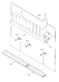
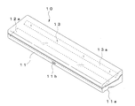
- Exploded perspective view of main parts of vending machine Front view of lighting device Perspective view of the lighting unit Bottom view of the lighting unit AA arrow direction sectional view of FIG. BB sectional view taken along line BB in FIG.
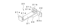
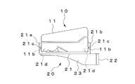
- Perspective view of bracket Side view of lighting unit and bracket Circuit diagram of lighting device Rear sectional view of the lighting unit Cross-sectional view of the main part of the lighting unit showing the connector storage state Bottom view of the main part of the lighting unit showing the storage state of the connector Side cross-sectional view of the main part of the vending machine showing the usage state of the lighting device
- the principal part back sectional view of the lighting unit which shows the 2nd Embodiment of this invention.
- Main unit rear sectional view of the lighting unit The principal part bottom view of the illumination unit which shows the 4th Embodiment of this invention.
- Side view of lighting unit Main unit rear sectional view of the lighting unit The principal part bottom view of the illumination unit which shows the 5th Embodiment of this invention.
- 1 to 14 show a first embodiment of the present invention.
- the vending machine shown in the figure includes a vending machine main body 1 having an open front, an outer door 2 for opening and closing the front of the vending machine main body 1, a product sample chamber 3 provided on the front of the outer door 2, The product sample chamber 3 is provided with a number of product samples 4 as illumination objects.
- An advertisement display room 5 is provided in front of the outer door 2.
- the vending machine main body 1 includes a heat-insulating product storage (not shown) inside, and a product column (not shown) such as a serpentine type is provided in the product storage.
- One end in the width direction of the outer door 2 is rotatably supported by the vending machine main body 1, and a plurality of product selection switches 2a, a coin insertion slot 2b, a bill insertion slot 2c, an amount display portion 2d, and a coin return are provided on the front surface thereof.
- a mouth 2e and a product outlet 2f are provided.
- the product sample chamber 3 includes a transparent plate 3a that covers the front surface of the product sample chamber 3, a back plate 3b that covers the back of the product sample chamber 3, and a plurality of upper and lower sample stages 3c attached to the back plate 3b.
- a plurality of product samples 4 are placed on each sample table 3c so as to be in a plurality of rows.
- the sample base 3c is made of a member bent in a substantially U-shaped cross section so as to open the lower surface, and an attachment hole 3d for attaching the product sample 4 is provided on the upper surface.
- the product sample 4 is made of a hollow light-transmitting member having an opening on the lower surface, and the surface has the same design as the actual product.
- An engaging portion 4a that engages with the mounting hole 3d of the sample table 3c is provided at the lower end of the product sample 4, and the product sample 4 is attached to the sample table 3c by engaging the engaging portion 4a with the mounting hole 3d. It is like that.
- an illumination device for illuminating the back plate 3 b of the product sample chamber 3 and the product sample 4 is provided.
- This illumination device includes a plurality of illumination units 10 arranged below the sample stage 3c and a bracket 20 that supports each illumination unit 10, and some of the illumination units 10 are wider than the other illumination units 10. It is formed so as to shorten the length.
- the illumination unit 10 includes a unit main body 11 extending in the width direction of the product sample chamber 3, a plurality of first LEDs 12 that emit light from the unit main body 11 toward the back plate 3b, and a product sample 4 above the unit main body 11. A plurality of second LEDs 13 that irradiate light toward the, and a connector 14 that connects the illumination units 10 to each other.
- the unit main body 11 is made of a horizontally-shaped hollow transparent member, and is sized to be placed inside the sample table 3c.
- the upper surface of the unit body 11 is formed to be inclined downward from the rear end side toward the front end side.
- a curved surface portion 11a that protrudes outward is provided on the lower surface front end side of the unit main body 11, and the curved surface portion 11a is formed so as to face obliquely downward toward the rear.
- Engagement portions 11b that engage with the brackets 30 are provided on the front surface and the back surface of the unit main body 11, and the engagement portions 11b include protrusions extending in the width direction.
- a pair of front and rear engaging holes 11 c that engage with the bracket 30 are provided on the bottom surface of the unit main body 11, and the engaging holes 11 c and the engaging portions 11 b are arranged at the same position in the longitudinal direction of the unit main body 11.
- the first LEDs 12 are mounted on the first substrate 12a and are arranged at intervals in the width direction (longitudinal direction) of the unit body 11.
- the first board 12a is arranged at the lower part of the front end in the unit body 11 so that the first LED 12 is located on the lower surface side, and the light of the first LED 12 is transmitted through the curved surface part 11a of the unit body 11 and directed rearward. Is irradiated obliquely downward. In this case, each 1st LED12 is mutually connected in series.
- the second LEDs 13 are mounted on the second substrate 13a and are arranged at intervals in the width direction (longitudinal direction) of the unit body 11.
- the second substrate 13a is disposed at the upper rear end in the unit main body 11 so that the second LED 13 is located on the upper surface side, and the light of the second LED 13 is transmitted through the upper surface of the unit main body 11 toward the front. It is irradiated obliquely upward. In this case, each 2nd LED13 is mutually connected in series.
- Each connector 14 is connected to both longitudinal ends of the first and second substrates 12a and 13a via wirings 14a.
- One connector 14 is a male connector and the other connector 14 is a female connector.
- the wiring 14a of the connector 14 is soldered to the first and second substrates 12a and 13a, respectively.
- Each connector 14 has a pair of terminals. As shown in FIG. 10, the first LED 12 is connected in series between one terminal of each connector 14, and the second terminal is connected between the other terminals of each connector 14. LEDs 13 are connected to each other in series.
- the partition wall 11f as a partition part which partitions off between the 1st board
- Each opening 11 d is formed in a rectangular shape and is provided on the lower surface of the unit body 11.
- the partition wall 11 f is formed so as to extend upward from the bottom surface in the unit main body 11, and a storage portion 11 e is formed by a space between the partition wall 11 f and the back surface in the unit main body 11.
- the storage portion 11e is provided on the center side in the longitudinal direction of the unit body 11 with respect to the opening portion 11d.
- the bracket 20 includes a support portion 21 that supports the unit main body 11, an attachment portion 22 that is fixed to the back plate 3 b of the product sample chamber 3, and an extension portion 23 that extends from the attachment portion 22 to below the support portion 21.
- the support part 21, the attachment part 22, and the extension part 23 are integrally formed of a transparent member such as acrylic.
- the support portion 21 is formed so as to extend in the front-rear direction, and a front wall portion 21 a and a rear wall portion 21 b extending upward along the front surface and the rear surface of the unit body 11 are provided at the front end and the rear end, respectively.
- groove portions 21c that engage with the engaging portions 11b of the unit body 11 are provided so as to extend in the width direction.
- a pair of front and rear projections 21 d that engage with the respective engagement holes 11 c of the unit main body 11 are provided on the bottom surface of the support portion 21 so as to protrude upward.
- the attachment portion 22 is formed so as to extend from the rear end of the extending portion 23 to both sides in the width direction, and mounting screw insertion holes 22a are provided at two places in the width direction.
- the extending portion 23 is provided between the lower surface of the support portion 21 and the front surface of the mounting portion 22, and the lower end thereof is inclined obliquely downward from the front end side to the rear end side of the support portion 21 and the rear end of the support portion 21. It is formed so as to extend in the horizontal direction from the side to the mounting portion 22.
- the lower end of the extending portion 23 has a sloped portion formed in a curved shape and is chamfered in a curved shape so as not to have a corner portion.
- each illumination unit 10 is attached to the back plate 3b of the product sample chamber 3 via the bracket 20.
- one illumination unit 10 that is short in the width direction and one illumination unit 10 that is long in the width direction are arranged below the sample table 3 c so as to be aligned in the width direction of the product sample chamber 3.
- the vending machine has a specification in which a fluorescent lamp is attached to the lower side of the sample table 3c, it can be changed to the specification of the LED illumination by attaching the illumination unit 10 instead of the fluorescent lamp.
- the wiring 31 from the external power supply 30 is connected to the connector 14 of the width direction one end side of the illumination unit 10 arrange
- a connector 14 on the other end side in the width direction of the illumination unit 10 and a connector 14 on one end side in the width direction of the illumination unit 10 arranged on the other end side in the width direction of the product sample chamber 3 are connected to each other.
- the wiring 14 a of the lighting unit 10 extends to the outside from the opening 11 d of the unit body 11, and the connector 14 is connected to the outside of the unit body 11.
- a short-circuit wiring 14 b is connected to the connector 14 on the other end side in the width direction of the illumination unit 10.
- the first LEDs 12 and 22 of each lighting unit 10 are connected to the power supply 30 in series.
- the connector 14 When the lighting units 10 are connected to each other by the connector 14, as shown in FIGS. 12 and 13, the connector 14 is inserted into the opening portion 11 d of one lighting unit 10 and stored in the storage portion 11 e, so that the connector 14 is It does not protrude outside the unit body 11. In this case, by pushing the connector 14 into the unit main body 11, a part of the wiring 14a is drawn into the unit main body 11 together with the connector 14, and the wiring 14a exposed to the outside is shortened. Further, since the first substrate 12a and the storage portion 11e are partitioned by the partition wall 11f, the connector 14 of the storage portion 11e does not move to the first substrate 12a side.
- the lighting device when the lighting device is turned on, in the lighting unit 10, the light of the first and second LEDs 12 and 13 is irradiated from the unit main body 11 to the outside.
- the upper part of the lower product sample 4 and the back plate 3 b are illuminated by the light of the first LED 12.
- the connector 14 since the connector 14 is housed in the housing portion 11e in the unit body 11, the connector 14 does not protrude outside from the lower surface of the unit body 11, and the connector 14 is irradiated with light emitted from the first LED 12. Is not projected on the product sample 4 side.
- the light of 2nd LED12 is irradiated to the inner surface of the product sample 4 through the mounting hole 3d of the sample stand 3c, and it illuminates so that the product sample 4 itself may shine.
- the wirings 14 a of the lighting unit 10 are connected to each other by the connector 14, and the connected connectors 14 are inserted into the opening 11 d provided on the lower surface of the unit body 11. Since the connector 14 is prevented from projecting to the outside from the lower surface of the unit body 11 by housing the housing in the housing portion 11e in the unit body 11, the shadow of the connector 14 caused by the light emitted from the first LED 12 is prevented. Can be prevented. Thereby, the appearance of the product sample chamber 3 is not deteriorated by the shadow of the connector 14, and the display effect of the product sample 4 can be enhanced.
- the connector 14 is housed in the unit body 11, so the connector 14 Water droplets can be prevented from adhering to the surface.
- the connector 14 stored in the storage portion 11e moves to the first substrate 12a side.
- the irradiation light of the first LED 12 of the first substrate 12a is not blocked by the connector 14 in the unit body 11.
- FIG. 15 shows a second embodiment of the present invention, and the same components as those in the first embodiment are denoted by the same reference numerals. Since the configuration other than the configuration shown in the figure is the same as that of the first embodiment, the illustration is omitted.
- the other end of the wiring 14a having one end connected to the connector 14 is connected to each of the substrates 12a and 13a by soldering.
- the other end of the wiring 14a is connected to the other.
- the connector 15 is connected to the first substrate 12a.
- the connector 15 includes a male connector and a female connector.
- One connector 15 is connected to the other end of the wiring 14a, and the other connector 15 is attached to the first substrate 12a.
- the second substrate 13a is connected to the first substrate 12a via a wiring (not shown).
- the wiring 14a and the first substrate 12a are connected by the other connector 15, soldering is not required for the connection of the wiring 14a, and the wiring connection work can be easily performed. it can.
- 16 and 17 show a third embodiment of the present invention, and the same components as those in the first embodiment are denoted by the same reference numerals. Since the configuration other than the configuration shown in the figure is the same as that of the first embodiment, the illustration is omitted.
- a wiring insertion hole 16a is provided on the lower surface of the unit body 11 as a wiring insertion portion for inserting the wiring 14a.
- the wiring insertion hole 16a is formed so as to communicate with the opening 11d.
- a wiring latch that restricts the movement of the wiring 14a from the wiring insertion hole 16a to the opening 11d.
- a portion 16b is provided.
- the wiring latching part 16b is formed so that the space
- the wiring 14a is connected to the wiring insertion hole 16a as shown in FIG. Since the wiring 14a can be held by the wiring insertion hole 16a, the wiring 14a is extremely effective in preventing the wiring 14a from drooping. In this case, the wiring 14a in the wiring insertion hole 16a is locked to the wiring locking portion 16b and is restricted from moving toward the opening 11d, so that the wiring 14a can be reliably held in the wiring insertion hole 16a. it can.
- FIG. 18 to FIG. 20 show a fourth embodiment of the present invention, and the same components as those in the first embodiment are denoted by the same reference numerals. Since the configuration other than the configuration shown in the figure is the same as that of the first embodiment, the illustration is omitted.
- a wiring insertion hole 16c is provided as a wiring insertion portion through which the wiring 14a is inserted in an end portion in the width direction of the unit main body 11 (an opposing surface of the adjacent unit main body 11).
- the wiring insertion hole 16c is formed so as to communicate with the opening 11d.
- a wiring latch that restricts the movement of the wiring 14a from the wiring insertion hole 16c to the opening 11d.
- a portion 16d is provided.
- the wiring locking portion 16d is formed so as to protrude upward in the wiring insertion hole 16c.
- the wiring 14a is connected to the wiring insertion hole 16c as shown in FIG. Since the wiring 14a can be held by the wiring insertion hole 16c, the wiring 14a is extremely effective in preventing the wiring 14a from drooping. In this case, since the wiring 14a in the wiring insertion hole 16c is locked by the wiring locking portion 16d and the movement toward the opening 11d is restricted, the wiring 14a can be reliably held in the wiring insertion hole 16c. it can. Moreover, since the wiring insertion hole 16c is provided in the opposing surface of the adjacent unit main bodies 11, the wiring 14a exposed between the unit main bodies 11 can be made very short.
- 21 to 23 show a fifth embodiment of the present invention, and the same reference numerals are given to the same components as those in the first embodiment. Since the configuration other than the configuration shown in the figure is the same as that of the first embodiment, the illustration is omitted.
- a wiring insertion groove 16e is provided on the lower surface of the unit body 11 as a wiring insertion portion for inserting the wiring 14a.
- the wiring insertion groove 16e is formed so that one end communicates with the opening 11d, and the other end opens at the width direction end of the unit body 11 (opposite surface of the adjacent unit bodies 11).
- a plurality of wiring locking portions 16f that restrict movement of the wiring 14a from the wiring insertion groove 16e to the outside are provided at the edge of the wiring insertion groove 16e. In this case, each wiring locking portion 16f is formed so as to protrude inward on both sides of the wiring insertion groove 16e.
- the wiring 14a is connected to the wiring insertion hole 16e as shown in FIG. Since the wiring 14a can be held by the wiring insertion hole 16e, the wiring 14a is extremely effective in preventing the wiring 14a from drooping. In this case, since the wiring 14a in the wiring insertion hole 16e is locked to the wiring locking portion 16f and the movement of the wiring insertion hole 16e to the outside is restricted, the wiring 14a is securely held in the wiring insertion hole 16e. be able to. Further, since the wiring insertion hole 16e is opened on the opposite surface of the adjacent unit main body 11 on the other end side, the wiring 14a exposed between the unit main bodies 11 can be extremely shortened.
- FIGS. 24 to 27 show a sixth embodiment of the present invention, and the same reference numerals are given to the same components as those in the first embodiment. Since the configuration other than the configuration shown in the figure is the same as that of the first embodiment, the illustration is omitted.
- the wiring 14a of the illumination unit 10 is extended to the outside from the opening 11d of the unit body 11, and the connector 14 is connected to the outside of the unit body 11.
- the connectors 17 attached to the unit main body 11 are connected to each other.
- the connector 17 includes a male connector and a female connector, and is connected to the first substrate 12a via the wiring 17a.
- the second substrate 13a is connected to the first substrate 12a via a wiring (not shown).
- the connector 17 is attached to the end surface in the width direction of the unit main body 11 (opposite surface of the adjacent unit main bodies 11).
- a cover portion 11g that covers the upper portion of the connector 17 exposed to the outside is provided at each end in the width direction of the unit main body 11.
- 11 g of cover parts consist of the protrusion part extended in the front-back direction along the upper end edge of the unit main body 11, and the position of the cover part 11g of the width direction one end and the other end of the unit main body 11 shifts
- the lighting units 10 adjacent to each other are arranged so that the end faces in the width direction of the unit main body 11 face each other so that the connectors 17 are connected to each other.
- the shadow of the connector 14 due to the light emitted from the first LED 12 can be prevented without protruding.
- the attachment strength of the connector 17 can be increased.
- the cover part 11g which covers the upper part of the connector 17 was provided in the edge part of the width direction of the unit main body 11, when replacing
- cover portions 11g at the one end in the width direction and the cover portions 11g at the other end of the unit body 11 are shifted in the vertical direction so as not to contact each other, the cover portions 11g overlap each other. Water droplets do not pass from between the cover portions 11g to the connector 17 side, and the waterproof effect on the connector 17 can be further enhanced.
- the wiring 14a of the illumination unit 10 is extended to the outside from the opening 11d of the unit body 11, and the connector 14 is connected to the outside of the unit body 11.
- the connectors 18 attached to the first substrate 12a are connected to each other.
- the connector 18 includes a male connector and a female connector.
- One connector 18 is attached to one longitudinal end of the first substrate 12a, and the other connector 18 is attached to the other longitudinal end of the first substrate 12a.
- the second substrate 13a is connected to the first substrate 12a via a wiring (not shown).
- the connector 18 protrudes to the outside from a hole 11 h provided in the end surface in the width direction of the unit main body 11 (an opposing surface of the adjacent unit main bodies 11).
- the lighting units 10 adjacent to each other are arranged so that the end faces in the width direction of the unit main body 11 face each other so that the connectors 18 are connected to each other.
- the projection of the shadow of the connector 14 due to the light emitted from the first LED 12 can be prevented without protruding.
- the connector 18 since the connector 18 is attached to the first substrate 12a, it is not necessary to connect the connector 18 to the first substrate 12a by wiring, and there is an advantage that wiring is unnecessary.
- the lighting units 10 having different lengths are arranged side by side. However, only the lighting units 10 having the same length may be arranged side by side. Moreover, in the said embodiment, what provided the 1st and 2nd LED12, 13 in the illumination unit 10 was shown, respectively, However, You may provide only the 1st LED12 which illuminates below, Only the second LED 13 that illuminates the light may be provided.
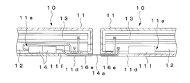
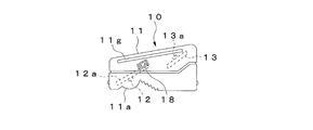
- SYMBOLS 3 Product sample chamber, 10 ... Illumination unit, 11 ... Unit main body, 11d ... Opening part, 11e ... Storage part, 11f ... Partition wall, 11g ... Cover part, 12 ... 1st LED, 13 ... 2nd LED, DESCRIPTION OF SYMBOLS 14 ... Connector, 14a ... Wiring, 15 ... Connector, 16a ... Wiring insertion hole, 16b ... Wiring locking part, 16c ... Wiring insertion hole, 16d ... Wiring locking part, 16e ... Wiring insertion groove, 16f ... Wiring locking part , 17 ... connector, 18 ... connector.
Landscapes
- Physics & Mathematics (AREA)
- General Physics & Mathematics (AREA)
- Control Of Vending Devices And Auxiliary Devices For Vending Devices (AREA)
Abstract
照明ユニット同士の配線接続のための外部突出物がユニット本体の光透過面に設けられることがなく、外部突出物による影の発生を効果的に防止することのできる自動販売機の照明装置を提供する。照明ユニット10の配線14a同士をコネクタ14によって接続するとともに、互いに接続されたコネクタ14をユニット本体11の下面に設けた開口部11dに挿入し、コネクタ14をユニット本体11内の収納部11eに収納することにより、コネクタ14がユニット本体11の下面から外部に突出しないようにしたので、第1のLED12から照射される光によるコネクタ14の影の発生を防止することができる。これにより、コネクタ14の影によって商品サンプル室3の見栄えが悪くなることがなく、商品サンプル4の展示効果を高めることができる。
Description
本発明は、例えば紙パック、缶、ビン、ペットボトル入りの商品を販売する自動販売機の照明装置に関するものである。
一般に、この種の自動販売機としては、前面を開口した自動販売機本体と、自動販売機本体の前面を開閉する外扉と、外扉の前面に設けられた商品サンプル室とを備え、商品サンプル室内に複数の商品サンプルを上下複数列に配置し、商品サンプル室内を蛍光灯によって照明するようにしたものが知られている。しかしながら、蛍光灯を用いたものでは、寿命に達した蛍光灯を定期的に交換しなければならず、メンテナンスの負担が大きいという問題がある。そこで、短期間で交換する必要のないLEDを光源として用いるようにした自動販売機の照明装置が提案されている(例えば、特許文献1参照)。
この照明装置は、光透過性のユニット本体内に外部に向かって発光するLEDを設けてなる照明ユニットを備え、複数の照明ユニットを商品サンプルの上方または下方に互いに幅方向に並べて配置するとともに、互いに隣り合う照明ユニット同士を通電用の配線を介して接続している。この照明装置では、複数の照明ユニットが商品サンプルの幅方向に並べて配置されることから、照明ユニットの個数を変えることにより、例えば上下各列の商品サンプルの数が異なる場合や、商品サンプル室または広告表示室の幅寸法が異なる複数種類の自動販売機に対応することができる。
また、前記照明装置では、照明ユニット同士を配線を介して接続するために、LEDの基板に取り付けたコネクタをユニット本体の下面に設けた開口部から外部に突出させ、コネクタ付きの配線を照明ユニットのコネクタに接続するようにしている。この場合、ユニット本体の下面に設けた配線保持部によって配線を保持することにより、配線の垂れ下がりを防止している(例えば、特許文献2参照)。
しかしながら、前記照明装置では、配線接続用のコネクタがユニット本体の下面(光透過面)から外部に突出しているため、LEDから照射される光によりコネクタの影が商品サンプル側に投影される。また、ユニット本体の下面には配線保持部が突設されているため、コネクタと同様、配線保持部の影も発生する。このため、これら外部突出物の影により商品サンプル室の見栄えが悪くなり、商品サンプルの展示効果を低下させていた。
本発明の目的とするところは、照明ユニット同士の配線接続のための外部突出物がユニット本体の光透過面に設けられることがなく、外部突出物による影の発生を効果的に防止することのできる自動販売機の照明装置を提供することにある。
本発明は前記目的を達成するために、光透過性のユニット本体内に外部に向かって発光するLEDを設けてなる照明ユニットを備え、複数の照明ユニットを互いに幅方向に並べて配置するとともに、互いに隣り合う照明ユニット同士を配線を介して接続し、照明ユニットの上下方向にLEDの光を照射するようにした自動販売機の照明装置において、前記各照明ユニットの配線同士を接続するコネクタを備え、ユニット本体の幅方向端部には、互いに接続されたコネクタをユニット本体内に挿入可能な開口部と、開口部から挿入されたコネクタを収納する収納部とを設けている。
これにより、照明ユニットの配線同士をコネクタによって接続するとともに、互いに接続されたコネクタをユニット本体に設けた開口部に挿入し、コネクタをユニット本体内の収納部に収納することにより、コネクタがユニット本体の外部に突出することがないので、照明ユニット同士の配線接続のための外部突出物がユニット本体の光透過面に設けられることがない。
また、本発明は前記目的を達成するために、光透過性のユニット本体内に外部に向かって発光するLEDを設けてなる照明ユニットを備え、複数の照明ユニットを互いに幅方向に並べて配置するとともに、互いに隣り合う照明ユニット同士を接続し、照明ユニットの上下方向にLEDの光を照射するようにした自動販売機の照明装置において、前記ユニット本体の幅方向端面に設けられ、LEDの基板に接続されたコネクタを備え、互いに隣接する照明ユニットをコネクタ同士が接続されるようにユニット本体の幅方向端面同士を対向させて配置している。
これにより、互いに隣接する照明ユニットを幅方向端面同士が対向するように配置することにより、ユニット本体の幅方向端面に設けられたコネクタ同士が接続されることから、照明ユニット同士の配線接続のための外部突出物がユニット本体の光透過面に設けられることがない。
本発明によれば、照明ユニット同士の配線接続のための外部突出物がユニット本体の光透過面に設けられることがないので、LEDから照射される光による外部突出物の影の発生を効果的に防止することができる。これにより、例えば商品サンプル室の商品サンプルを照明する場合、外部突出物の影によって商品サンプル室の見栄えが悪くなることがないので、商品サンプルの展示効果を高めることができる。
図1乃至図14は本発明の第1の実施形態を示すものである。
同図に示す自動販売機は、前面を開口した自動販売機本体1と、自動販売機本体1の前面を開閉する外扉2と、外扉2の前面に設けられた商品サンプル室3と、を備え、商品サンプル室3内には照明対象物としての多数の商品サンプル4が設けられている。また、外扉2の前面には広告表示室5が設けられている。
自動販売機本体1は内部に断熱性の商品収納庫(図示せず)を備え、商品収納庫内にはサーペンタイン式等の商品コラム(図示せず)が設けられている。
外扉2は幅方向一端を自動販売機本体1に回動自在に支持され、その前面には、複数の商品選択スイッチ2a、硬貨投入口2b、紙幣投入口2c、金額表示部2d、硬貨返却口2e及び商品取出口2fが設けられている。
商品サンプル室3は、商品サンプル室3の前面を覆う透明板3aと、商品サンプル室3の背面を覆う背面板3bと、背面板3bに取り付けられた上下複数段のサンプル台3cとを有し、各サンプル台3cには複数の商品サンプル4が上下複数列になるように載置されている。サンプル台3cは下面を開口するように断面略コ字状に屈曲した部材からなり、その上面には商品サンプル4を取り付けるための取付孔3dが設けられている。
商品サンプル4は下面を開口した中空状の光透過性部材からなり、その表面には実物の商品と同様のデザインが施されている。商品サンプル4の下端にはサンプル台3cの取付孔3dに係合する係合部4aが設けられ、取付孔3dに係合部4aを係合することにより商品サンプル4がサンプル台3cに取り付けられるようになっている。
また、商品サンプル室3内には、商品サンプル室3の背面板3b及び商品サンプル4を照明する照明装置が設けられている。
この照明装置は、サンプル台3cの下方に配置される複数の照明ユニット10と、各照明ユニット10を支持するブラケット20とを備え、一部の照明ユニット10は他の照明ユニット10よりも幅方向の長さが短くなるように形成されている。
照明ユニット10は、商品サンプル室3の幅方向に延びるユニット本体11と、ユニット本体11から背面板3bに向かって光を照射する複数の第1のLED12と、ユニット本体11から上方の商品サンプル4に向かって光を照射する複数の第2のLED13と、照明ユニット10同士を接続するコネクタ14とを備えている。
ユニット本体11は横長に形成された中空状の透明部材からなり、サンプル台3cの内側に配置可能な大きさに形成されている。ユニット本体11の上面は後端側から前端側に向かって下り傾斜をなすように形成されている。ユニット本体11の下面前端側には外側に向かって凸状をなす曲面部11aが設けられ、曲面部11aは後方に向かって斜め下方を臨むように形成されている。ユニット本体11の前面及び背面にはブラケット30に係合する係合部11bが設けられ、係合部11bは幅方向に延びる突起からなる。ユニット本体11の底面にはブラケット30に係合する前後一対の係合孔11cが設けられ、係合孔11c及び係合部11bはそれぞれユニット本体11の長手方向同一位置に配置されている。
各第1のLED12は第1の基板12aに実装され、互いにユニット本体11の幅方向(長手方向)に間隔をおいて配置されている。第1の基板12aは第1のLED12が下面側に位置するようにユニット本体11内の前端下部に配置され、第1のLED12の光がユニット本体11の曲面部11aを透過し、後方に向かって斜め下方に照射されるようになっている。この場合、各第1のLED12は互いに直列に接続されている。
各第2のLED13は第2の基板13aに実装され、互いにユニット本体11の幅方向(長手方向)に間隔をおいて配置されている。第2の基板13aは第2のLED13が上面側に位置するようにユニット本体11内の後端上部に配置され、第2のLED13の光がユニット本体11の上面を透過し、前方に向かって斜め上方に照射されるようになっている。この場合、各第2のLED13は互いに直列に接続されている。
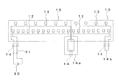
各コネクタ14は、第1及び第2の基板12a,13aの長手方向両端にそれぞれ配線14aを介して接続され、一方のコネクタ14は雄コネクタからなり、他方のコネクタ14は雌コネクタからなる。この場合、コネクタ14の配線14aは第1及び第2の基板12a,13aにそれぞれ半田付けされている。各コネクタ14は一対の端子を有し、図10に示すように各コネクタ14の一方の端子間には第1のLED12が互いに直列に接続され、各コネクタ14の他方の端子間には第2のLED13が互いに直列に接続されている。
また、ユニット本体11の幅方向両端部には、互いに接続された一対のコネクタ14をユニット本体11内に挿入可能な開口部11dと、開口部11dから挿入されたコネクタ14を収納する収納部11eと、第1の基板12aと収納部11eとの間を仕切る仕切部としての仕切壁11fが設けられている。各開口部11dは四角形状に形成され、ユニット本体11の下面に設けられている。仕切壁11fはユニット本体11内の底面から上方に延びるように形成され、仕切壁11fとユニット本体11内の背面との間の空間によって収納部11eが形成されている。この場合、収納部11eは開口部11dに対してユニット本体11の長手方向中央側に設けられている。
ブラケット20は、ユニット本体11を支持する支持部21と、商品サンプル室3の背面板3bに固定される取付部22と、取付部22から支持部21の下方まで延びる延出部23とからなり、支持部21、取付部22及び延出部23はアクリル等の透明部材によって一体に形成されている。支持部21は前後方向に延びるように形成され、その前端及び後端にはそれぞれユニット本体11の前面及び背面に沿って上方に延びる前壁部21a及び後壁部21bが設けられている。また、前壁部21aの背面及び後壁部21bの前面には、それぞれユニット本体11の係合部11bに係合する溝部21cが幅方向に延びるように設けられている。更に、支持部21の底面にはユニット本体11の各係合孔11cに係合する前後一対の突部21dが上方に突出するように設けられている。取付部22は延出部23の後端から幅方向両側に延びるように形成され、その幅方向二箇所に取り付用のネジ挿通孔22aが設けられている。延出部23は支持部21の下面と取付部22の前面との間に設けられ、その下端は支持部21の前端側から後端側まで斜め下方に傾斜するとともに、支持部21の後端側から取付部22まで水平方向に延びるように形成されている。この場合、延出部23の下端は傾斜部が曲線状に形成されるとともに、角部を有しないように曲線状に面取りされている。
以上のように構成された照明装置においては、各照明ユニット10がブラケット20を介して商品サンプル室3の背面板3bに取り付けられる。例えば、図3に示すように幅方向に短い一つの照明ユニット10と幅方向に長い一つの照明ユニット10が互いに商品サンプル室3の幅方向に並ぶようにサンプル台3cの下方に配置される。この場合、サンプル台3cの下方に蛍光灯が取り付けられる仕様の自動販売機であっても、蛍光灯に代えて照明ユニット10を取り付けることにより、LED照明の仕様に変更することが可能となる。
また、前記照明装置では、図3に示すように商品サンプル室3の幅方向一端側に配置された照明ユニット10の幅方向一端側のコネクタ14に外部の電源30からの配線31が接続され、照明ユニット10の幅方向他端側のコネクタ14と商品サンプル室3の幅方向他端側に配置される照明ユニット10の幅方向一端側のコネクタ14とが互いに接続される。この場合、図11に示すように照明ユニット10の配線14aはユニット本体11の開口部11dから外部に延出しており、コネクタ14はユニット本体11の外部で接続される。また、照明ユニット10の幅方向他端側のコネクタ14には短絡用の配線14bが接続される。これにより、図10に示すように各照明ユニット10の第1のLED12,22が電源30に直列に接続される。
コネクタ14によって照明ユニット10同士を接続する際、図12及び図13に示すように、コネクタ14を一方の照明ユニット10の開口部11dに挿入して収納部11eに収納することにより、コネクタ14がユニット本体11の外部に突出することがない。この場合、コネクタ14をユニット本体11内に押し込むことにより、配線14aの一部がコネクタ14と共にユニット本体11内に引き込まれ、外部に露出する配線14aが短くなる。また、第1の基板12aと収納部11eとの間は仕切壁11fによって仕切られているので、収納部11eのコネクタ14が第1の基板12a側に移動することがない。
次に、前記照明装置を点灯すると、照明ユニット10では、第1及び第2のLED12,13の光がユニット本体11から外部に照射される。これにより、図14に示すように第1のLED12の光によって下方の商品サンプル4の上部及び背面板3bが照明される。その際、コネクタ14はユニット本体11内の収納部11eに収納されているので、コネクタ14がユニット本体11の下面から外部に突出することがなく、第1のLED12から照射される光によりコネクタ14の影が商品サンプル4側に投影されることがない。また、第2のLED12の光はサンプル台3cの取付孔3dを介して商品サンプル4の内面に照射され、商品サンプル4自体が光るように照明される。
このように、本実施形態によれば、照明ユニット10の配線14a同士をコネクタ14によって接続するとともに、互いに接続されたコネクタ14をユニット本体11の下面に設けた開口部11dに挿入し、コネクタ14をユニット本体11内の収納部11eに収納することにより、コネクタ14がユニット本体11の下面から外部に突出しないようにしたので、第1のLED12から照射される光によるコネクタ14の影の発生を防止することができる。これにより、コネクタ14の影によって商品サンプル室3の見栄えが悪くなることがなく、商品サンプル4の展示効果を高めることができる。
この場合、配線14aの一部をコネクタ14と共にユニット本体11内に引き込むことができるので、外部に露出する配線14aを短くすることができるとともに、ユニット本体11の下面に配線14aを保持するための配線保持部を設ける必要もなく、このような外部突出物による影の発生も効果的に防止することができる。
更に、商品サンプル4を交換する場合など、商品サンプル室3を開放した際に雨などの水滴が照明ユニット10にかかった場合でも、コネクタ14はユニット本体11内に収納されているので、コネクタ14への水滴の付着を防止することができる。
また、ユニット本体11内に、第1の基板12aと収納部11eとの間を仕切る仕切壁11fを設けたので、収納部11eに収納されたコネクタ14が第1の基板12a側に移動することがなく、ユニット本体11内のコネクタ14によって第1の基板12aの第1のLED12の照射光が遮られることがないという利点がある。
図15は本発明の第2の実施形態を示すものであり、第1の実施形態と同等の構成部分には同一の符号を付して示す。尚、同図に示す構成以外の構成は、第1の実施形態と同等であるため図示を省略する。
第1の実施形態では、一端にコネクタ14が接続された配線14aの他端を各基板12a,13aに半田付けにより接続したものを示したが、本実施形態では、配線14aの他端を他のコネクタ15によって第1の基板12aに接続している。このコネクタ15は、雄コネクタ及び雌コネクタからなり、一方のコネクタ15は配線14aの他端に接続され、他方のコネクタ15は第1の基板12aに取り付けられている。この場合、第2の基板13aは図示しない配線を介して第1の基板12aに接続されている。
本実施形態によれば、配線14aと第1の基板12aとを他のコネクタ15によって接続するようにしたので、配線14aの接続に半田付けを必要とせず、配線接続作業を容易に行うことができる。
図16及び図17は本発明の第3の実施形態を示すものであり、第1の実施形態と同等の構成部分には同一の符号を付して示す。尚、同図に示す構成以外の構成は、第1の実施形態と同等であるため図示を省略する。
本実施形態では、ユニット本体11の下面に配線14aを挿通する配線挿通部としての配線挿通孔16aが設けられている。配線挿通孔16aは開口部11dに連通するように形成され、開口部11dと配線挿通孔16aとの間には、配線挿通孔16aから開口部11dへの配線14aの移動を規制する配線係止部16bが設けられている。この場合、配線係止部16bは、配線挿通孔16aと開口部11dとの連通部分の間隔を狭くするように形成されている。
本実施形態によれば、コネクタ14をユニット本体11の開口部11dに挿入し、コネクタ14をユニット本体11内の収納部11eに収納した後、図17に示すように配線14aを配線挿通孔16aに挿通することにより、配線14aを配線挿通孔16aによって保持することができるので、配線14aの垂れ下がりを防止する上で極めて効果的である。この場合、配線挿通孔16a内の配線14aは配線係止部16bに係止して開口部11d側への移動を規制されるので、配線14aを配線挿通孔16a内に確実に保持することができる。
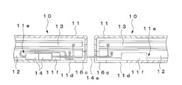
図18乃至図20は本発明の第4の実施形態を示すものであり、第1の実施形態と同等の構成部分には同一の符号を付して示す。尚、同図に示す構成以外の構成は、第1の実施形態と同等であるため図示を省略する。
本実施形態では、ユニット本体11の幅方向端部(隣り合うユニット本体11の対向面)に配線14aを挿通する配線挿通部としての配線挿通孔16cが設けられている。配線挿通孔16cは開口部11dに連通するように形成され、開口部11dと配線挿通孔16cとの間には、配線挿通孔16cから開口部11dへの配線14aの移動を規制する配線係止部16dが設けられている。この場合、配線係止部16dは、配線挿通孔16c内に上方に突出するように形成されている。
本実施形態によれば、コネクタ14をユニット本体11の開口部11dに挿入し、コネクタ14をユニット本体11内の収納部11eに収納した後、図20に示すように配線14aを配線挿通孔16cに挿通することにより、配線14aを配線挿通孔16cによって保持することができるので、配線14aの垂れ下がりを防止する上で極めて効果的である。この場合、配線挿通孔16c内の配線14aは配線係止部16dに係止して開口部11d側への移動を規制されるので、配線14aを配線挿通孔16c内に確実に保持することができる。また、配線挿通孔16cは隣り合うユニット本体11の対向面に設けられているので、ユニット本体11間に露出する配線14aを極めて短くすることができる。
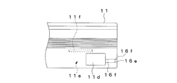
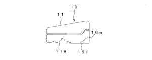
図21乃至図23は本発明の第5の実施形態を示すものであり、第1の実施形態と同等の構成部分には同一の符号を付して示す。尚、同図に示す構成以外の構成は、第1の実施形態と同等であるため図示を省略する。
本実施形態では、ユニット本体11の下面に配線14aを挿通する配線挿通部としての配線挿通溝16eが設けられている。配線挿通溝16eは一端が開口部11dに連通するように形成され、その他端はユニット本体11の幅方向端部(隣り合うユニット本体11の対向面)に開口している。配線挿通溝16eの縁部には、配線挿通溝16eから外部への配線14aの移動を規制する複数の配線係止部16fが設けられている。この場合、各配線係止部16fは、配線挿通溝16eの両側に内側に向かって突出するように形成されている。
本実施形態によれば、コネクタ14をユニット本体11の開口部11dに挿入し、コネクタ14をユニット本体11内の収納部11eに収納した後、図23に示すように配線14aを配線挿通孔16eに挿通することにより、配線14aを配線挿通孔16eによって保持することができるので、配線14aの垂れ下がりを防止する上で極めて効果的である。この場合、配線挿通孔16e内の配線14aは配線係止部16fに係止して配線挿通孔16eの外部への移動を規制されるので、配線14aを配線挿通孔16e内に確実に保持することができる。また、配線挿通孔16eは他端側を隣り合うユニット本体11の対向面に開口しているので、ユニット本体11間に露出する配線14aを極めて短くすることができる。
図24乃至図27は本発明の第6の実施形態を示すものであり、第1の実施形態と同等の構成部分には同一の符号を付して示す。尚、同図に示す構成以外の構成は、第1の実施形態と同等であるため図示を省略する。
第1乃至第5の実施形態では、照明ユニット10の配線14aをユニット本体11の開口部11dから外部に延出させ、コネクタ14をユニット本体11の外部で接続するようにしているが、本実施形態では、ユニット本体11に取り付けられたコネクタ17同士を接続するようにしている。
コネクタ17は、雄コネクタ及び雌コネクタからなり、第1の基板12aに配線17aを介して接続されている。この場合、第2の基板13aは図示しない配線を介して第1の基板12aに接続されている。また、コネクタ17は、ユニット本体11の幅方向端面(隣り合うユニット本体11の対向面)に取り付けられている。
更に、ユニット本体11の幅方向端部には、外部に露出するコネクタ17の上方を覆うカバー部11gがそれぞれ設けられている。カバー部11gはユニット本体11の上端縁に沿って前後方向に延びる突条部からなり、ユニット本体11の幅方向一端と他端のカバー部11gは互いに当接しないように上下方向に位置がずれている。
本実施形態によれば、互いに隣接する照明ユニット10をコネクタ17同士が接続されるようにユニット本体11の幅方向端面同士を対向させて配置したので、コネクタ17がユニット本体11の下面から外部に突出することがなく、第1の実施形態と同様、第1のLED12から照射される光によるコネクタ14の影の発生を防止することができる。この場合、コネクタ17をユニット本体11に取り付けるようにしたので、コネクタ17の取付強度を高めることができる。
また、ユニット本体11の幅方向端部に、コネクタ17の上方を覆うカバー部11gを設けたので、商品サンプル4を交換する場合など、商品サンプル室3を開放した際に雨などの水滴が照明ユニット10にかかった場合でも、カバー部11gによってコネクタ17への水滴の付着を防止することができる。
この場合、ユニット本体11の幅方向一端と他端のカバー部11gを互いに当接しないように上下方向に位置をずらして設けることにより、各カバー部11gが互いに上下に重なり合うようにしたので、各カバー部11gの間からコネクタ17側に水滴が通過することがなく、コネクタ17に対する防水効果をより高めることができる。
図28及び図31は本発明の第7の実施形態を示すものであり、第1及び第6の実施形態と同等の構成部分には同一の符号を付して示す。尚、同図に示す構成以外の構成は、第1の実施形態と同等であるため図示を省略する。
第1乃至第5の実施形態では、照明ユニット10の配線14aをユニット本体11の開口部11dから外部に延出させ、コネクタ14をユニット本体11の外部で接続するようにしているが、本実施形態では、第1の基板12aに取り付けられたコネクタ18同士を接続するようにしている。
コネクタ18は、雄コネクタ及び雌コネクタからなり、一方のコネクタ18は第1の基板12aの長手方向一端に取り付けられ、他方のコネクタ18は第1の基板12aの長手方向他端に取り付けられている。この場合、第2の基板13aは図示しない配線を介して第1の基板12aに接続されている。また、コネクタ18は、ユニット本体11の幅方向端面(隣り合うユニット本体11の対向面)に設けられた孔11hから外部に突出している。
本実施形態によれば、互いに隣接する照明ユニット10をコネクタ18同士が接続されるようにユニット本体11の幅方向端面同士を対向させて配置したので、コネクタ18がユニット本体11の下面から外部に突出することがなく、第1の実施形態と同様、第1のLED12から照射される光によるコネクタ14の影の発生を防止することができる。この場合、コネクタ18を第1の基板12aに取り付けるようにしたので、コネクタ18を配線によって第1の基板12aに接続する必要がなく、配線が不要になるという利点がある。
尚、前記実施形態では、長さの異なる照明ユニット10を互いに並べて配置したものを示したが、同一長さの照明ユニット10のみを並べて配置するようにしてもよい。また、前記実施形態では、照明ユニット10に第1及び第2のLED12,13をそれぞれ設けたものを示したが、下方を照明する第1のLED12のみを備えたものであってもよく、上方を照明する第2のLED13のみを備えたものであってもよい。
3…商品サンプル室、10…照明ユニット、11…ユニット本体、11d…開口部、11e…収納部、11f…仕切壁、11g…カバー部、12…第1のLED、13…第2のLED、14…コネクタ、14a…配線、15…コネクタ、16a…配線挿通孔、16b…配線係止部、16c…配線挿通孔、16d…配線係止部、16e…配線挿通溝、16f…配線係止部、17…コネクタ、18…コネクタ。
Claims (10)
- 光透過性のユニット本体内に外部に向かって発光するLEDを設けてなる照明ユニットを備え、複数の照明ユニットを互いに幅方向に並べて配置するとともに、互いに隣り合う照明ユニット同士を配線を介して接続し、照明ユニットの上下方向にLEDの光を照射するようにした自動販売機の照明装置において、
前記各照明ユニットの配線同士を接続するコネクタを備え、
ユニット本体の幅方向端部には、互いに接続されたコネクタをユニット本体内に挿入可能な開口部と、開口部から挿入されたコネクタを収納する収納部とが設けられている
ことを特徴とする自動販売機の照明装置。 - 前記ユニット本体には、配線を挿通する配線挿通部が前記開口部に連通するように設けられている
ことを特徴とする請求項1記載の自動販売機の照明装置。 - 前記ユニット本体には、配線挿通部内の配線に係止することにより配線挿通部から開口部への配線の移動を規制する配線係止部が設けられている
ことを特徴とする請求項2記載の自動販売機の照明装置。 - 前記ユニット本体内には、LEDの基板と前記収納部との間を仕切る仕切部が設けられている
ことを特徴とする請求項1、2または3記載の自動販売機の照明装置。 - 前記配線とLEDの基板とが他のコネクタによって接続されている
ことを特徴とする請求項1、2、3または4記載の自動販売機の照明装置。 - 光透過性のユニット本体内に外部に向かって発光するLEDを設けてなる照明ユニットを備え、複数の照明ユニットを互いに幅方向に並べて配置するとともに、互いに隣り合う照明ユニット同士を接続し、照明ユニットの上下方向にLEDの光を照射するようにした自動販売機の照明装置において、
前記ユニット本体の幅方向端面に設けられ、LEDの基板に接続されたコネクタを備え、
互いに隣接する照明ユニットは、コネクタ同士が接続されるようにユニット本体の幅方向端面同士を対向させて配置されている
ことを特徴とする自動販売機の照明装置。 - 前記ユニット本体の幅方向端部には、コネクタの少なくとも上方を覆うカバー部が設けられている
ことを特徴とする請求項6記載の自動販売機の照明装置。 - 互いに隣接する照明ユニットの一方のユニット本体のカバー部と他方のユニット本体のカバー部とが互いに上下に重なり合うように形成されている
ことを特徴とする請求項7記載の自動販売機の照明装置。 - 前記コネクタは、ユニット本体に取り付けられるとともに、配線を介してLEDの基板に接続されている
ことを特徴とする請求項6、7または8記載の自動販売機の照明装置。 - 前記コネクタはLEDの基板に取り付けられている
ことを特徴とする請求項6、7または8記載の自動販売機の照明装置。
Priority Applications (1)
| Application Number | Priority Date | Filing Date | Title |
|---|---|---|---|
| CN2011800345834A CN102985954A (zh) | 2010-07-14 | 2011-07-11 | 自动售货机的照明装置 |
Applications Claiming Priority (2)
| Application Number | Priority Date | Filing Date | Title |
|---|---|---|---|
| JP2010159284A JP5555563B2 (ja) | 2010-07-14 | 2010-07-14 | 自動販売機の照明装置 |
| JP2010-159284 | 2010-07-14 |
Publications (1)
| Publication Number | Publication Date |
|---|---|
| WO2012008404A1 true WO2012008404A1 (ja) | 2012-01-19 |
Family
ID=45469403
Family Applications (1)
| Application Number | Title | Priority Date | Filing Date |
|---|---|---|---|
| PCT/JP2011/065781 Ceased WO2012008404A1 (ja) | 2010-07-14 | 2011-07-11 | 自動販売機の照明装置 |
Country Status (3)
| Country | Link |
|---|---|
| JP (1) | JP5555563B2 (ja) |
| CN (1) | CN102985954A (ja) |
| WO (1) | WO2012008404A1 (ja) |
Families Citing this family (4)
| Publication number | Priority date | Publication date | Assignee | Title |
|---|---|---|---|---|
| JP2014112299A (ja) * | 2012-12-05 | 2014-06-19 | Sanden Corp | 自動販売機 |
| JP6136465B2 (ja) * | 2013-03-29 | 2017-05-31 | 富士電機株式会社 | 自動販売機 |
| JP6418306B1 (ja) | 2017-11-07 | 2018-11-07 | オムロン株式会社 | 照明装置及び展示装置 |
| JP2023534289A (ja) * | 2020-07-17 | 2023-08-08 | ペプシコ・インク | 容器詰飲料を照明するための陳列装置 |
Citations (5)
| Publication number | Priority date | Publication date | Assignee | Title |
|---|---|---|---|---|
| JPS61195076U (ja) * | 1985-05-27 | 1986-12-04 | ||
| JPH01100172U (ja) * | 1987-12-22 | 1989-07-05 | ||
| JPH01320596A (ja) * | 1988-06-22 | 1989-12-26 | Toshiba Corp | 自動販売機 |
| JP2001338505A (ja) * | 2000-05-26 | 2001-12-07 | Matsushita Electric Works Ltd | 照明装置 |
| JP2009211399A (ja) * | 2008-03-04 | 2009-09-17 | Sanden Corp | 自動販売機の照明装置 |
Family Cites Families (2)
| Publication number | Priority date | Publication date | Assignee | Title |
|---|---|---|---|---|
| JP4268106B2 (ja) * | 2004-09-09 | 2009-05-27 | 豊田合成株式会社 | 発光装置 |
| JP5226345B2 (ja) * | 2008-03-04 | 2013-07-03 | サンデン株式会社 | 自動販売機の照明装置及びこれを備えた自動販売機 |
-
2010
- 2010-07-14 JP JP2010159284A patent/JP5555563B2/ja not_active Expired - Fee Related
-
2011
- 2011-07-11 WO PCT/JP2011/065781 patent/WO2012008404A1/ja not_active Ceased
- 2011-07-11 CN CN2011800345834A patent/CN102985954A/zh active Pending
Patent Citations (5)
| Publication number | Priority date | Publication date | Assignee | Title |
|---|---|---|---|---|
| JPS61195076U (ja) * | 1985-05-27 | 1986-12-04 | ||
| JPH01100172U (ja) * | 1987-12-22 | 1989-07-05 | ||
| JPH01320596A (ja) * | 1988-06-22 | 1989-12-26 | Toshiba Corp | 自動販売機 |
| JP2001338505A (ja) * | 2000-05-26 | 2001-12-07 | Matsushita Electric Works Ltd | 照明装置 |
| JP2009211399A (ja) * | 2008-03-04 | 2009-09-17 | Sanden Corp | 自動販売機の照明装置 |
Also Published As
| Publication number | Publication date |
|---|---|
| JP2012022482A (ja) | 2012-02-02 |
| JP5555563B2 (ja) | 2014-07-23 |
| CN102985954A (zh) | 2013-03-20 |
Similar Documents
| Publication | Publication Date | Title |
|---|---|---|
| RU2676056C2 (ru) | Индикаторное устройство и бытовой прибор с таким индикаторным устройством | |
| JP5555563B2 (ja) | 自動販売機の照明装置 | |
| JP6661990B2 (ja) | 照明装置 | |
| JP6615540B2 (ja) | Led照明器具 | |
| JP5226346B2 (ja) | 自動販売機の照明装置及びこれを備えた自動販売機 | |
| JP5226345B2 (ja) | 自動販売機の照明装置及びこれを備えた自動販売機 | |
| JP6315373B2 (ja) | 光源ユニット及び照明器具 | |
| US7806582B2 (en) | Illuminating module for mounting in a domestic appliance and domestic appliance with such a module | |
| JP5975400B2 (ja) | 照明器具 | |
| JP3158658U (ja) | 陳列棚の照明装置 | |
| JP2013077572A (ja) | 陳列棚の照明装置 | |
| US20160018099A1 (en) | Illuminating device for a household appliance and household appliance with such an illuminating device | |
| JP6167448B2 (ja) | 厨房装置 | |
| CN103017013A (zh) | 照明器具 | |
| KR101553947B1 (ko) | 냉장고 | |
| JP6048883B2 (ja) | 厨房装置 | |
| JP2019212414A (ja) | 照明器具 | |
| JP7108950B2 (ja) | 照明装置 | |
| JP5552524B2 (ja) | 陳列棚の照明装置 | |
| JP2015032569A (ja) | 照明器具 | |
| JP5861097B2 (ja) | 照明器具 | |
| JP6100645B2 (ja) | 陳列棚の照明装置 | |
| JP6134171B2 (ja) | 陳列棚の照明装置 | |
| JP2016103058A (ja) | 照明装置及びこれを用いた自動販売機 | |
| JP6294185B2 (ja) | 照明装置 |
Legal Events
| Date | Code | Title | Description |
|---|---|---|---|
| WWE | Wipo information: entry into national phase |
Ref document number: 201180034583.4 Country of ref document: CN |
|
| 121 | Ep: the epo has been informed by wipo that ep was designated in this application |
Ref document number: 11806734 Country of ref document: EP Kind code of ref document: A1 |
|
| NENP | Non-entry into the national phase |
Ref country code: DE |
|
| 122 | Ep: pct application non-entry in european phase |
Ref document number: 11806734 Country of ref document: EP Kind code of ref document: A1 |