WO2012005102A1 - 光ピックアップ対物レンズ及び光ピックアップ装置 - Google Patents
光ピックアップ対物レンズ及び光ピックアップ装置 Download PDFInfo
- Publication number
- WO2012005102A1 WO2012005102A1 PCT/JP2011/063962 JP2011063962W WO2012005102A1 WO 2012005102 A1 WO2012005102 A1 WO 2012005102A1 JP 2011063962 W JP2011063962 W JP 2011063962W WO 2012005102 A1 WO2012005102 A1 WO 2012005102A1
- Authority
- WO
- WIPO (PCT)
- Prior art keywords
- optical pickup
- objective lens
- tangent angle
- angle
- pickup objective
- Prior art date
- Legal status (The legal status is an assumption and is not a legal conclusion. Google has not performed a legal analysis and makes no representation as to the accuracy of the status listed.)
- Ceased
Links
Images











Classifications
-
- G—PHYSICS
- G11—INFORMATION STORAGE
- G11B—INFORMATION STORAGE BASED ON RELATIVE MOVEMENT BETWEEN RECORD CARRIER AND TRANSDUCER
- G11B7/00—Recording or reproducing by optical means, e.g. recording using a thermal beam of optical radiation by modifying optical properties or the physical structure, reproducing using an optical beam at lower power by sensing optical properties; Record carriers therefor
- G11B7/12—Heads, e.g. forming of the optical beam spot or modulation of the optical beam
- G11B7/135—Means for guiding the beam from the source to the record carrier or from the record carrier to the detector
- G11B7/1372—Lenses
- G11B7/1374—Objective lenses
-
- G—PHYSICS
- G02—OPTICS
- G02B—OPTICAL ELEMENTS, SYSTEMS OR APPARATUS
- G02B13/00—Optical objectives specially designed for the purposes specified below
- G02B13/18—Optical objectives specially designed for the purposes specified below with lenses having one or more non-spherical faces, e.g. for reducing geometrical aberration
-
- G—PHYSICS
- G11—INFORMATION STORAGE
- G11B—INFORMATION STORAGE BASED ON RELATIVE MOVEMENT BETWEEN RECORD CARRIER AND TRANSDUCER
- G11B7/00—Recording or reproducing by optical means, e.g. recording using a thermal beam of optical radiation by modifying optical properties or the physical structure, reproducing using an optical beam at lower power by sensing optical properties; Record carriers therefor
- G11B7/12—Heads, e.g. forming of the optical beam spot or modulation of the optical beam
- G11B7/135—Means for guiding the beam from the source to the record carrier or from the record carrier to the detector
- G11B7/1365—Separate or integrated refractive elements, e.g. wave plates
- G11B7/1367—Stepped phase plates
-
- G—PHYSICS
- G11—INFORMATION STORAGE
- G11B—INFORMATION STORAGE BASED ON RELATIVE MOVEMENT BETWEEN RECORD CARRIER AND TRANSDUCER
- G11B7/00—Recording or reproducing by optical means, e.g. recording using a thermal beam of optical radiation by modifying optical properties or the physical structure, reproducing using an optical beam at lower power by sensing optical properties; Record carriers therefor
- G11B7/12—Heads, e.g. forming of the optical beam spot or modulation of the optical beam
- G11B7/135—Means for guiding the beam from the source to the record carrier or from the record carrier to the detector
- G11B7/1392—Means for controlling the beam wavefront, e.g. for correction of aberration
- G11B7/13922—Means for controlling the beam wavefront, e.g. for correction of aberration passive
-
- G—PHYSICS
- G11—INFORMATION STORAGE
- G11B—INFORMATION STORAGE BASED ON RELATIVE MOVEMENT BETWEEN RECORD CARRIER AND TRANSDUCER
- G11B7/00—Recording or reproducing by optical means, e.g. recording using a thermal beam of optical radiation by modifying optical properties or the physical structure, reproducing using an optical beam at lower power by sensing optical properties; Record carriers therefor
- G11B2007/0003—Recording, reproducing or erasing systems characterised by the structure or type of the carrier
- G11B2007/0009—Recording, reproducing or erasing systems characterised by the structure or type of the carrier for carriers having data stored in three dimensions, e.g. volume storage
- G11B2007/0013—Recording, reproducing or erasing systems characterised by the structure or type of the carrier for carriers having data stored in three dimensions, e.g. volume storage for carriers having multiple discrete layers
Definitions
- the present invention relates to an objective lens for an optical pickup device mounted on an optical information reproducing device for recording / reproducing information on an optical recording medium (optical disc), and particularly used for an optical disc having a plurality of information recording layers of three or more layers.
- an optical pickup objective lens capable of forming a light spot of an appropriate size on each information recording layer with little deterioration of wavefront aberration, and an optical pickup equipped with this optical pickup objective lens Relates to the device.
- Blu-ray disc (registered trademark), a high-density optical disc with a recording capacity of 25 GB using a blue-violet laser, is commercialized as a type with two information recording layers, so-called double-layer disc, for further increase in capacity. Has been.
- an optical pickup objective lens mounted on an optical pickup device for Blu-ray is designed to focus on the thickness of the cover layer at 0.0875 mm in the middle of the information recording layer in order to support a double-layer disc. Is done.
- wavefront aberration occurs if the thickness of the cover layer is different from the designed thickness.
- a collimator is provided with a movable mechanism, and wavefront aberration is compensated by changing the object distance of the light beam incident on the optical pickup objective lens.
- the optical pickup objective lens for Blu-ray has a large numerical aperture NA of 0.85, and if plastic is used as the material, the change in refractive index when the ambient temperature changes is large, so that the wavefront aberration increases.
- a multi-layer disc having a cover glass thickness of two or more layers has been developed. This is because the cover layer thickness is 0.05 mm to 0.1 mm, which is twice as large as before, and there is a concern that the wavefront aberration due to the change in the disc thickness is about twice as large as that of the two-layer disc.
- FIG. 1 shows a calculation result of Conventional Example 1 (Example 2 of Patent Document 1).
- the high-order spherical aberration at positions 0.075 mm and 0.1 mm deep from the cover layer surface in Conventional Example 1 was calculated, it was 7.3 m ⁇ rms at 0.075 mm and 5.5 m ⁇ rms at 0.1 mm.
- FIG. 2 shows the calculation result of Conventional Example 2 (Example 3 of Patent Document 1).
- the high-order spherical aberration at positions 0.075 mm and 0.1 mm deep from the surface of the cover layer in Conventional Example 2 was calculated, it was 7.6 m ⁇ rms at 0.075 mm and 6.9 m ⁇ rms at 0.1 mm.
- Patent Document 1 proposes a method for improving the temperature characteristics by attaching a ring zone.
- the cover layer thickness changes the amount of high-order spherical aberration generated increases.
- a lens having a refractive index of 1.52 or less is further difficult to design, and the amount of high-order spherical aberration generated when the cover layer thickness changes is increased.
- An object of the present invention is to provide high-order spherical aberration even when the disc thickness changes in a plastic optical pickup objective lens having a numerical aperture NA of 0.84 or more provided with an annular step for improving temperature characteristics.
- An object of the present invention is to provide an optical pickup objective lens and an optical pickup device that can form an appropriately sized light spot at a depth position of each information recording surface without generating as much as possible.
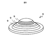
- FIG. 5 shows an example of an optical pickup objective lens 6 according to the present invention.
- an annular structure composed of a plurality of annular zones 9 having different concentric sizes is formed on at least one surface of the optical pickup objective lens 6 according to the present invention.
- step difference is formed between the ring zones which adjoin each ring zone structure. Due to this level difference, a phase difference is generated between the light beams transmitted through the respective annular zones.
- the phase of the transmitted laser light is set to be different in wavelength units between adjacent annular zones. That is, when the laser light is incident on the optical pickup objective lens 6 under the same conditions as the design, the phases of the laser light transmitted through each annular zone 9 are different from each other by an integral multiple of the wavelength.
- the phase difference of the laser light transmitted through each annular zone 9 is not an integral multiple of the wavelength. Therefore, when the wavelength changes, a phase difference occurs in the laser light transmitted through the different annular zone 9. This phase difference is so large as to reduce aberrations caused by changes in the ambient temperature.
- each annular zone 9 is optimized to have a different surface shape so as to balance the design wavefront aberration and the ambient temperature.
- the wavefront aberration is suppressed by adjusting the position of the collimator lens. Therefore, when the cover layer thickness deviates from the design, the laser light incident on the optical pickup objective lens 6 is divergent light or convergent light.
- the third-order spherical aberration can be canceled, but the higher-order spherical aberration remains.
- FIG. 6 is an explanatory diagram of a tangent angle in the present invention.
- the tangent angle is ⁇ in FIG. 6, and is an angle formed by a tangent at a point where a surface perpendicular to the optical axis intersects the lens surface and a surface perpendicular to the optical axis.
- the normalized ray height h is a value obtained by normalizing the outermost circumference of the lens effective diameter to 1, and the tangent angle ⁇ (h) is an approximate tangent angle (°) at the normalized ray height h.
- the surface shape at a certain radius is greatly different. Spherical aberration is generated.
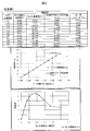
- FIG. 3 is a diagram in which the tangent angle of the second surface of Conventional Example 2 is plotted. In the design that does not satisfy Formula 1, the tangent angle of the second surface is not a smooth curve as shown in FIG.
- the paraxial NA hereinafter referred to as “NA0”
- NAM NA of the marginal ray
- the light spot in this invention is The light spot diameter satisfies the following conditions.
- Spot diameter ratio calculated spot diameter / theoretical spot diameter
- Spot diameter theoretical value 0.82 ⁇ ⁇ / NA0, Defined in
- the focal length f is Is desirable.
- the reason why 1.15 ⁇ f is preferable is to secure a working distance.
- the curvature radius R of the first surface and the second surface of the optical pickup objective lens 6 is decreased, and as a result, the edge thickness is decreased.
- the edge thickness is reduced, problems such as breaking of the edge occur, and it becomes difficult to attach the optical pickup objective lens 6.
- the optical pickup objective lens 6 that satisfies the expressions (1) and (2) at the same time, even if the cover layer thickness is different from 0.075 mm or 0.1 mm, the light does not deteriorate the wavefront aberration and the spot diameter.
- the pickup objective lens 6 can be designed.
- the wavefront aberration and the spot diameter are deteriorated even in a disc 7 having a wide cover layer thickness of 0.05 mm to 0.1 mm and a plurality of information recording surfaces of three or more layers such as the multilayer disc 7. It can be used without.
- the optical pickup objective lens of the present invention is a plastic optical pickup objective lens having a numerical aperture of 0.84 or more mounted on an optical pickup device for recording and reproducing information on an optical information recording medium having a plurality of information recording surfaces.
- this optical pickup objective lens at least one surface has an annular shape, and blue-violet laser light having a wavelength of 380 nm to 430 nm is incident on the optical pickup objective lens, and approximates to a tangent angle ⁇ (h).
- the tangent angle ⁇ and the normalized ray height h satisfy the following conditional expression.
- the tangent angle ⁇ (h) is the tangent angle (°) at the ray height h
- the angle (°) value and the normalized ray height h are values obtained by normalizing the outermost circumference of the lens effective diameter to 1.
- the optical pickup objective lens of the present invention is further characterized in that the focal length f (mm) satisfies the following expression.
- the optical pickup objective lens of the present invention is made of a plastic having a numerical aperture of 0.84 or more mounted on an optical pickup device for recording and reproducing information on an optical information recording medium having a plurality of information recording surfaces of three or more layers.
- the optical pickup objective lens has an annular shape at least on one surface, and a blue-violet laser beam having a wavelength of 380 nm to 430 nm is incident on the optical pickup objective lens so that a tangential angle is obtained.
- ⁇ (h) the approximate tangent angle ⁇ , and the normalized ray height h satisfy the following conditional expression.
- the normalized ray height h is a value obtained by normalizing the outermost circumference of the lens effective diameter to 1, and the tangent angle ⁇ (h) is an approximate tangent angle (°) at the normalized ray height h.
- the optical pickup device of the present invention is equipped with the above optical pickup objective lens.
- the optical pickup device of the present invention is an optical pickup device capable of recording and reproducing an information recording medium having a cover layer thickness of 3 or more and having a plurality of information recording surfaces of 3 or more.
- the optical pickup objective lens is mounted.
- the present invention it is possible to improve both the wavefront aberration and the light spot of the optical pickup objective lens.
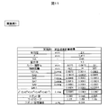
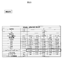
- FIG. 1 shows a calculation result according to Conventional Example 1 (Example 2 of Patent Document 1).
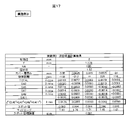
- FIG. 2 is a calculation result according to Conventional Example 2 (Example 3 of Patent Document 1).
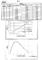
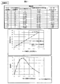
- FIG. 3 is a table of relative pupil coordinates and tangent angles according to Conventional Example 1, a graph of R1 plane relative pupil coordinates and tangent angles, and a normalized ray height and tangent angle on the R2 plane (the exit surface of the optical pickup objective lens).
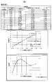
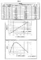
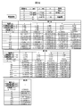
- FIG. FIG. 4 is a table of relative pupil coordinates and tangent angles according to Conventional Example 2, a graph of R1 plane relative pupil coordinates and tangent angles, and a normalized ray height and tangent angle on the R2 plane (the exit surface of the optical pickup objective lens).
- FIG. 5 is a shape diagram of the optical pickup objective lens according to the present embodiment.
- FIG. 6 is a diagram illustrating the tangent angle of the optical pickup objective lens according to the present embodiment.
- FIG. 7 is a diagram for explaining definitions of symbols of the optical pickup objective lens according to the present embodiment.
- FIG. 8 is a diagram for explaining the normalized ray height of the R1 surface and the normalized ray height of the R2 surface of the optical pickup objective lens.
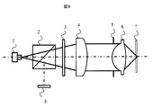
- FIG. 9 is a diagram illustrating an example of the optical pickup optical system 1 according to the present embodiment.
- FIG. 10 is a table showing aspherical coefficients, curvatures, and the like of the objective lens according to Example 1 of the present invention.
- FIG. 11 shows the results according to Example 1 of the present invention.
- FIG. 12 is a table of relative pupil coordinates and tangent angles according to Example 1 of the present invention, a graph of R1 plane relative pupil coordinates and tangent angles, and a normalized ray height on the R2 plane (the exit surface of the optical pickup objective lens). It is a figure showing the relationship between the angle and the tangent angle.
- FIG. 13 is a table showing aspherical coefficients, curvatures, and the like of the objective lens according to Example 2 of the present invention.
- FIG. 14 shows the results according to Example 2 of the present invention.
- FIG. 15 is a table of relative pupil coordinates and tangent angles, a graph of R1 plane relative pupil coordinates and tangent angles, and a normalized ray height on the R2 plane (the exit surface of the optical pickup objective lens) according to the second embodiment of the present invention. It is a figure showing the relationship between the angle and the tangent angle.
- FIG. 16 is a table showing aspherical coefficients, curvatures, and the like of the objective lens according to Example 3 of the present invention.
- FIG. 17 shows the results according to Example 3 of the present invention.
- FIG. 18 is a table of relative pupil coordinates and tangent angles, a graph of R1 plane relative pupil coordinates and tangent angles, and a normalized ray height on the R2 plane (the exit surface of the optical pickup objective lens) according to the third embodiment of the present invention. It is a figure showing the relationship between the angle and the tangent angle.
- FIG. 19 is a table showing aspheric coefficients, curvatures, and the like of the objective lens according to Example 4 of the present invention.
- FIG. 20 shows the results according to Example 4 of the present invention.
- FIG. 21 is a table of relative pupil coordinates and tangent angles according to Example 4 of the present invention, a graph of R1 surface relative pupil coordinates and tangent angles, and a normalized ray height on the R2 surface (the exit surface of the optical pickup objective lens). It is a figure showing the relationship between the angle and the tangent angle.
- FIG. 22 is a table showing aspheric coefficients, curvatures, and the like of the objective lens according to Example 5 of the present invention.
- FIG. 23 shows the results according to Example 5 of the present invention.
- R 24 is a table of relative pupil coordinates and tangent angles, a graph of R1 plane relative pupil coordinates and tangent angles, and a normalized ray height on the R2 plane (the exit surface of the optical pickup objective lens) according to the fifth embodiment of the present invention. It is a figure showing the relationship between the angle and the tangent angle.
- FIG. 8 is a diagram schematically showing a configuration of the optical pickup device PU1 of the present embodiment that can appropriately record and reproduce information on the Blu-ray disc (BD) 7. As shown in FIG.
- Such an optical pickup device PU1 can be mounted on an optical information recording / reproducing device.
- the optical pickup device PU1 is used when recording and reproducing information on the BD 7 and emits a laser beam of 380 nm or more.
- a beam splitter 2 is provided on the optical path of the laser light. By passing through the beam splitter 2 and the quarter wavelength plate 3, it is converted into circularly polarized light.
- a coupling lens 4 is provided on the optical path of the laser light emitted from the quarter-wave plate 3.
- the coupling lens 4 is formed of a plastic material or a glass material, and is spread to light having an appropriate angle by moving the coupling lens 4 in the optical axis direction by an actuator.
- the appropriate angle is generally an angle set so that the wavefront aberration when reaching the disk 7 is minimized.
- the light passing through the coupling lens 4 passes through the diaphragm 5 and then enters the optical pickup objective lens 6 having the annular structure 9.
- the cover layer thickness in the multilayer disk 7 is changed, it is designed not to generate higher-order spherical aberration.
- the light having an appropriate spot and the numerical aperture NA of 0.85, the light is incident on the information recording surface of the optical disc 7.
- the laser beam reflected by the information recording surface of the optical disc 7 enters the photodetector 8 through the optical pickup objective lens 6 and is detected.
- the photodetector 8 detects the laser beam, performs photoelectric conversion, and outputs an output signal. Based on the output signal of the photodetector 8, a focus error signal, a track error signal, a reproduction signal, and the like are generated. Further, recording and / or reproduction of the optical disk 7 is performed using the focus error signal, track error signal, reproduction signal, and the like.
- Example 1 according to the present invention will be described.
- the table shown in FIG. 10 shows the refractive index, the center thickness, the width of the annular zone 9, the step difference of the annular zone 9, the aspherical coefficient, and the curvature of the optical pickup objective lens 6 of the optical pickup apparatus PU1 according to the first embodiment.
- the coefficient shown in FIG. 10 is used as a coefficient of the formula (5) described later. Therefore, the surface shape of the optical pickup objective lens 6 according to the example 1 is expressed by Expression (5) using the coefficients shown in FIG.
- Zj is an aspherical shape
- h is the height of the light beam from the optical axis
- C is the curvature
- K is the conic coefficient
- FIG. 11 shows the results of Example 1 of the present invention.
- the refractive index is as low as 1.50.
- the higher-order spherical aberration is 6.5 m ⁇ rms when the cover layer thickness is 0.075 mm, and the higher-order spherical aberration is 6.7 m ⁇ rms when the cover layer thickness is 0.1 mm. ing.
- the spot diameter at the cover layer thickness of 0.075 mm is 0.393 ⁇ m
- the spot diameter at the cover layer thickness of 0.0875 mm is 0.394 ⁇ m
- the spot diameter at 0.1 mm is 0.395 ⁇ m. Since the theoretical value of the spot diameter is 0.391 ⁇ m, it can be seen that the spot diameter is sufficiently small.
- the information recording surface of the optical disc 7 is a three-layer Blu-ray optical disc provided at a cover layer thickness of 0.075 mm, 0.0875 mm, and 0.1 mm.
- High-order spherical aberration is sufficiently small, and the spot diameter is also sufficiently small, so that the Blu-ray laser light can be converged well.
- the information recording surface of the optical disc 7 is applied to a two-layer Blu-ray optical disc provided at a position where the cover layer thickness is 0.075 mm and 0.1 mm, and the focus is set to an intermediate position of 0.0875 mm, Even if the position of the focal point fluctuates, the wavefront aberration is sufficiently small and the spot diameter is sufficiently small on each information recording surface, so that the Blu-ray laser light can be converged well.
- the ray height h and the tangent angle ⁇ (h) are It is designed to be a straight line that satisfies
- FIG. 12 is a diagram illustrating the relationship between the normalized ray height and the tangent angle on the R2 surface (the exit surface of the optical pickup objective lens) according to the first embodiment.
- the horizontal axis of FIG. 12 indicates the normalized light beam height relative to the normalized light beam height 1 on the R2 plane (the exit surface of the optical pickup objective lens) indicated by point B in FIG.
- the axis indicates the tangent angle of the R2 plane.
- the tangential angle ⁇ (i) of R2 increases from the central portion of the optical pickup lens 6 as the normalized light beam height increases, and then gently toward the lens periphery of the optical pickup lens 6. Becomes a curve in which the tangent angle ⁇ (i) decreases.
- the table shown in FIG. 13 shows the refractive index, the center thickness, the width of the annular zone 9, the level difference of the annular zone 9, the aspherical coefficient, and the curvature of the optical pickup objective lens 6 of the optical pickup apparatus PU1 according to the second embodiment.
- the coefficients shown in FIG. 13 are used as the coefficients in the above formula (5). Therefore, the surface shape of the optical pickup objective lens 6 according to the second embodiment is expressed by Expression (5) using the coefficients shown in FIG.
- FIG. 14 shows the results of Example 2.
- the high-order spherical aberration at the cover layer thickness of 0.075 mm is 5.1 m ⁇ rms
- the high-order spherical aberration at 0.1 mm is 4.4 m ⁇ rms
- the high-order spherical aberration is sufficiently small.
- the spot diameter at a cover layer thickness of 0.075 mm is 0.393 ⁇ m
- the spot diameter at 0.1 mm is 0.395 ⁇ m. Since the theoretical value of the spot diameter is 0.391 ⁇ m, it can be seen that the spot diameter is sufficiently small.
- the information recording surface of the optical disc 7 is a three-layer Blu-ray optical disc provided with cover layer thicknesses of 0.075 mm, 0.0875 mm, and 0.1 mm. High-order spherical aberration is sufficiently small, and the spot diameter is also sufficiently small, so that the Blu-ray laser light can be converged well.
- the information recording surface of the optical disc 7 is applied to a two-layer Blu-ray optical disc provided at a position where the cover layer thickness is 0.075 mm and 0.1 mm, and the focus is set to an intermediate position of 0.0875 mm, Even if the position of the focal point fluctuates, the high-order spherical aberration is sufficiently small on each information recording surface, and the spot diameter is also sufficiently small, so that the Blu-ray laser beam can be converged well.
- the light ray height h and the tangent angle ⁇ (h) are It is designed to be a straight line that satisfies
- FIG. 15 is a diagram illustrating the relationship between the normalized ray height and the tangent angle on the R2 surface (the exit surface of the optical pickup objective lens) according to the second embodiment.
- the horizontal axis in FIG. 15 indicates the relative normalized beam height with respect to the normalized beam height 1 on the R2 plane (the exit surface of the optical pickup objective lens) indicated by point B in FIG.
- the axis indicates the tangent angle of the R2 plane.
- the tangent angle ⁇ (i) of R2 increases from the central portion of the optical pickup lens 6 as the normalized light beam height increases, and then gently toward the lens periphery of the optical pickup lens 6. Becomes a curve in which the tangent angle ⁇ (i) decreases.
- This embodiment is used for a multilayer disk, and the cover layer thickness is in the range of 0.05 mm to 0.1 mm.
- the cover layer thickness is designed to be 0.075 mm which is an intermediate cover layer thickness of 0.05 mm to 0.1 mm.
- the table shown in FIG. 16 shows the refractive index, the center thickness, the width of the annular zone 9, the step amount of the annular zone 9, the aspherical coefficient, and the curvature of the optical pickup objective lens 6 of the optical pickup apparatus PU1 according to the third embodiment.
- the coefficient shown in FIG. 16 is used as a coefficient of Equation (5) described later. Therefore, the surface shape of the optical pickup objective lens 6 according to the example 3 is expressed by Equation (5) using the coefficients shown in FIG.
- FIG. 17 shows the results of Example 3.
- the higher-order spherical aberration at the cover layer thickness of 0.05 mm is 12.6 m ⁇ rms
- the wavefront aberration at 0.0625 mm is 5.6 m ⁇ rms
- the higher-order spherical aberration at 0.075 mm is 0.2 mm.
- the higher order spherical aberration at 0 m ⁇ rms and 0.0875 mm is 4.8 m ⁇ rms and the higher order spherical aberration at 0.1 mm is 9.3 m ⁇ rms, and the higher order spherical aberration is sufficiently small.
- the spot diameter at a cover layer thickness of 0.05 mm is 0.393 ⁇ m
- the spot diameter at 0.0625 mm is 0.394 ⁇ m
- the spot diameter at 0.075 mm is 0.394 ⁇ m
- the spot diameter at 0.0875 mm is 0.396 ⁇ m.
- the spot diameter at 0.1 mm is 0.396 ⁇ m. Since the theoretical value of the spot diameter is 0.391 ⁇ m, it can be seen that the spot diameter is sufficiently small.
- Example 3 of the present invention in an information recording surface of an optical disc 7 in a five-layer Blu-ray optical disc provided with cover layer thicknesses of 0.05 mm, 0.0625 mm, 0.075 mm, 0.0875 mm, and 0.1 mm.
- cover layer thicknesses 0.05 mm, 0.0625 mm, 0.075 mm, 0.0875 mm, and 0.1 mm.
- high-order spherical aberration is sufficiently small on each information recording surface, and the spot diameter is sufficiently small, so that the Blu-ray laser beam can be converged well.
- the information recording surface of the optical disc 7 is applied to a three-layer Blu-ray optical disc provided with cover layer thicknesses of 0.05 mm, 0.075 mm, and 0.1 mm, and positions of 0.0625 mm and 0.0875 mm in the middle. Even when the focus is adjusted, the high-order spherical aberration is sufficiently small on each information recording surface, and the spot diameter is sufficiently small on each information recording surface. Can do.
- the ray height h and the tangent angle ⁇ (h) are It is designed to be a straight line that satisfies
- FIG. 18 is a diagram illustrating the relationship between the normalized ray height and the tangent angle on the R2 surface (the exit surface of the optical pickup objective lens) according to the third embodiment.
- the horizontal axis in FIG. 18 indicates the relative normalized beam height with respect to the normalized beam height 1 on the R2 plane (the exit surface of the optical pickup objective lens) indicated by point B in FIG.
- the axis indicates the tangent angle of the R2 plane.
- the tangent angle ⁇ (i) of R2 increases from the central portion of the optical pickup lens 6 as the normalized light beam height increases, and thereafter gently toward the lens periphery of the optical pickup lens 6. It becomes a curve in which the tangent angle ⁇ (i) decreases.
- the table shown in FIG. 19 shows the refractive index, the center thickness, the width of the annular zone 9, the step difference of the annular zone 9, the aspherical coefficient, and the curvature of the optical pickup objective lens 6 of the optical pickup apparatus PU1 according to the fourth embodiment.
- the coefficients shown in FIG. 19 are used as the coefficients of the above formula (5). Therefore, the surface shape of the optical pickup objective lens 6 according to the example 4 is expressed by Expression (5) using the coefficients shown in FIG.
- FIG. 20 shows the results of Example 4.
- Example 4 has the same effective diameter, focal length f, NA, and refractive index as Conventional Example 1, and is designed to be equivalent to Example 4.
- the higher order spherical aberration at the cover layer thickness of 0.075 mm is 3.6 m ⁇ rms
- the higher order spherical aberration at 0.1 mm is 3.2 m ⁇ rms.
- 0.0625 mm and 0.1125 mm which are 0.025 mm apart from 0.0875
- 0.0625 mm is 8.2 m ⁇ rms
- 0.1125 mm is 6.3 m ⁇ rms
- the average value is 7.25 m ⁇ rms. . It can be seen that the average value is 5.35 m ⁇ rms smaller than that of Conventional Example 1.
- the spot diameter at the cover layer thickness of 0.0625 mm is 0.391 ⁇ m
- the spot diameter at 0.075 mm is 0.391 ⁇ m
- the spot diameter at 0.1 mm is 0.393 ⁇ m
- the spot diameter at 0.1125 mm is 0.394 ⁇ m. It has become. Since the theoretical value of the spot diameter is 0.391 ⁇ m, it can be seen that the spot diameter is sufficiently small.
- the ray height h and the tangent angle ⁇ (h) are It is designed to be a straight line that satisfies
- FIG. 21 is a diagram illustrating the relationship between the normalized ray height and the tangent angle on the R2 surface (the exit surface of the optical pickup objective lens) according to the fourth embodiment.
- the horizontal axis in FIG. 21 indicates the normalized light beam height relative to the normalized light beam height 1 on the R2 surface (the exit surface of the optical pickup objective lens) indicated by point B in FIG.
- the axis indicates the tangent angle of the R2 plane.
- the tangent angle ⁇ (i) of R2 increases from the central portion of the optical pickup lens 6 as the normalized ray height increases, and then gently toward the lens periphery of the optical pickup lens 6. Becomes a curve in which the tangent angle ⁇ (i) decreases.
- the table shown in FIG. 22 shows the refractive index, the center thickness, the width of the annular zone 9, the stepped amount of the annular zone 9, the aspherical coefficient, and the curvature of the optical pickup objective lens 6 of the optical pickup apparatus PU1 according to the fifth embodiment.
- the coefficients shown in FIG. 22 are used as the coefficients of the above mathematical formula (5). Therefore, the surface shape of the optical pickup objective lens 6 according to the example 4 is expressed by Expression (5) using the coefficients shown in FIG.
- FIG. 23 shows the results of Example 5.
- Example 5 has the same effective diameter, focal length f, NA, and refractive index as Conventional Example 2, and is designed to be equivalent to Example 4.
- Example 5 the higher order spherical aberration at the cover layer thickness of 0.075 mm is 4.9 m ⁇ rms, and the higher order spherical aberration at 0.1 mm is 5.5 m ⁇ rms.
- 0.0625 mm and 0.1125 mm which are 0.025 mm apart from 0.0875, are calculated, 0.0625 mm is 9.1 m ⁇ rms, 0.1125 mm is 11.7 m ⁇ rms, and the average value is 10.4 m ⁇ rms. .
- the average value is 3.7 m ⁇ rms smaller than that of Conventional Example 2.
- the spot diameter at the cover layer thickness of 0.0625 mm is 0.391 ⁇ m
- the spot diameter at 0.075 mm is 0.392 ⁇ m
- the spot diameter at 0.1 mm is 0.392 ⁇ m
- the spot diameter at 0.1125 mm is 0.393 ⁇ m. It has become. Since the theoretical value of the spot diameter is 0.391 ⁇ m, it can be seen that the spot diameter is sufficiently small.
- the ray height h and the tangent angle ⁇ (h) are It is designed to be a straight line that satisfies
- FIG. 24 is a diagram illustrating the relationship between the normalized ray height and the tangent angle on the R2 surface (the exit surface of the optical pickup objective lens) according to the fifth example.
- the horizontal axis of FIG. 24 indicates the normalized ray height relative to the normalized ray height 1 on the R2 plane (the exit surface of the optical pickup objective lens) indicated by point B in FIG.
- the axis indicates the tangent angle of the R2 plane.
- the contact angle ⁇ (i) of R2 increases from the central portion of the optical pickup lens 6 as the normalized light beam height increases, and thereafter gently toward the lens periphery of the optical pickup lens 6. Becomes a curve in which the tangent angle ⁇ (i) decreases.
- Optical pickup device PU 1 Optical pickup device PU 2 Beam splitter 3 1/4 wavelength plate 4 Coupling lens 5 Aperture 6 Optical pickup objective lens 7 Multilayer disc 8 Photo detector 9 Ring zone
Landscapes
- Physics & Mathematics (AREA)
- Optics & Photonics (AREA)
- General Physics & Mathematics (AREA)
- Optical Head (AREA)
- Lenses (AREA)
Abstract
温度特性改善のための輪帯段差を設けた開口数NAが0.84以上のプラスチック製光ピックアップ対物レンズにおいて、ディスク厚が変化した場合にも、高次球面収差をできる限り発生させることなく、適切なサイズの光スポットを3個以上の各情報記録面の深さ位置に形成することができる光ピックアップ対物レンズ及び光ピックアップ装置を提供する。 光ピックアップ対物レンズの接線角θ(h)と近似接線角φと規格化光線高さhとが以下の条件式を満足する。-1<接線角θ(h)-(近似接線角φ×規格化光線高さh)<+1、但し、接線角θ(h)は、光線高さhの時の接線角(°)、近似接線角φは、接線角θ(h)の各点を線形近似した時のh=1の時の角度(°)の値、規格化光線高さhは、レンズ有効径の最外周を1に規格化した値である。
Description
本発明は、光記録媒体(光ディスク)の情報を記録再生する光情報再生装置に搭載される光ピックアップ装置用の対物レンズに関し、特に、3層以上の複数の情報記録層を有する光ディスクに使用したときでも、波面収差の劣化が小さく、且つ、各情報記録層に適切なサイズの光スポットを形成することができるプラスチック製の光ピックアップ対物レンズの構造、およびこの光ピックアップ対物レンズを搭載した光ピックアップ装置に関する。
青紫色レーザーを使った記録容量25GBの高密度光ディスクのブルーレイディスク(Blu-ray disc:登録商標)では更なる高容量化のため、情報記録層を2層もつタイプ、いわゆる2層ディスクが製品化されている。
これは光ディスクのカバー層表面から0.075mmと0.100mmの深さに2層の情報記録層を設けることで、50GBもの記録容量を達成している。一般的に、Blu-ray用の光ピックアップ装置に搭載する光ピックアップ対物レンズは、2層ディスクに対応するため、カバー層の厚みを情報記録層の中間の0.0875mmに焦点を結ぶように設計される。
この光ピックアップ対物レンズを使って、各層を記録再生する場合、カバー層の厚みが設計の厚みと異なる場合には、波面収差が発生してしまう。これを補正するためにコリメータに可動機構を設けて、光ピックアップ対物レンズに入射する光束の物体距離を変えることで波面収差を補償している。
また、Blu-ray用の光ピックアップ対物レンズは開口数NAが0.85と大きく、材料にプラスチックを使うと周囲温度が変化したときの屈折率変化が大きい為、波面収差が増大してしまう。
特に、近年ではさらなる記憶容量増大の為、カバーガラス厚みが2層以上ある多層ディスクが開発されている。これはカバー層厚みが0.05mmから0.1mmと今までよりも2倍広くなっており、ディスク厚変化による波面収差が2層ディスクに比べ、2倍程度大きくなる事が懸念される。
一般に、対物レンズを2層ディスクに使用する場合には、3次球面収差をキャンセルする為にカバー層厚み0.075mmでは収束光、0.1mmでは発散光が使用されるが、この時、高次球面収差(以下、高次球面収差は√(SA52+SA72+SA92+SA112)を示す)はキャンセルする事が出来ない事が知られている。
特許文献1の実施例についての波面収差計算結果とスポット径計算結果を図1~3に記載した。
図1は、従来例1(特許文献1の実施例2)の計算結果を示している。従来例1におけるカバー層表面から0.075mmと0.1mmの深さの位置の高次球面収差について計算したところ、0.075mmで7.3mλrms、0.1mmで5.5mλrmsとなった。
これを多層ディスクとして仮定し、設計ディスク厚み0.0875mmから0.025mmずれた0.0625mmと0.1125mmで計算してみたところ、0.0625mmでは13.4mλrms、0.1125mmでは11.8mλrmsとなった。平均値は12.6mλrmsであり、高次球面収差が発生している。
図2は、従来例2(特許文献1の実施例3)の計算結果を示している。従来例2におけるカバー層表面から0.075mmと0.1mmの深さの位置の高次球面収差について計算したところ、0.075mmで7.6mλrms、0.1mmで6.9mλrmsとなった。
これを多層ディスクとして仮定し、設計ディスク厚み0.0875mmから0.025mmずれた0.0625mmと0.1125mmで計算してみたところ、0.0625mmでは14.4mλrms、0.1125mmでは13.8mλrmsとなった。平均値は14.1mλrmsであり、高次球面収差が発生している。
このように、複数層あるディスクでは高次球面収差の劣化がおこる。特にプラスチックレンズの場合には温度特性を改善する方法として、例えば特許文献1では輪帯をつける事で温度特性を改善する方法が提案されているが、このような輪帯がついた場合には、カバー層厚みが変化した場合に高次球面収差の発生量が大きくなる。また、屈折率が1.52以下のレンズでは更に設計が困難になりカバー層厚みが変化した時の高次球面収差発生量が大きくなる。
本発明の目的は、温度特性改善のための輪帯段差を設けた開口数NAが0.84以上のプラスチック製の光ピックアップ対物レンズにおいて、ディスク厚が変化した場合にも、高次球面収差をできる限り発生させることなく、適切なサイズの光スポットを各情報記録面の深さ位置に形成することができる光ピックアップ対物レンズ及び光ピックアップ装置を提供することにある。
図5に本発明にかかわる光ピックアップ対物レンズ6の一例を示す。図5に示すように、本発明にかかわる光ピックアップ対物レンズ6の少なくとも一方の面には、同心の大きさの異なる複数の輪帯9からなる輪帯構造が形成される。そして、各輪帯構造のとなり合う輪帯間には段差が形成されている。この段差により、それぞれの輪帯を透過する光束間に位相差が生じる。
光ピックアップ対物レンズの設計においては、透過したレーザー光の位相が隣接する輪帯間において波長単位で異なるように設定されている。すなわち、設計と同条件でレーザー光が光ピックアップ対物レンズ6に入射する場合、各輪帯領域9を透過したレーザー光の位相は相互に波長の整数倍だけ異なる。
したがって、光ピックアップ対物レンズ6から出射したレーザー光には位相差が発生せず光ピックアップ対物レンズ6から出射されるレーザー光の収差は、段差が形成されていない光ピックアップ対物レンズから出射されるレーザー光の収差とほぼ同じとなる。
一方、周辺温度が変化し、波長が変化したレーザー光が光ピックアップ対物レンズ6に入射する場合、各輪帯領域9を透過したレーザー光の位相の違いは波長の整数倍とならない。したがって、波長が変化した場合には、異なる輪帯領域9を透過したレーザー光に位相差が発生する。そしてこの位相差は、周辺温度が変化したことによって発生する収差を低減するような大きさとなっている。
さらに、周辺温度が変化した場合の収差を小さくするため、各輪帯9は設計での波面収差と周辺温度が変化した場合のバランスをとるように、異なる面形状に最適化されている。
一般に、カバー層厚が設計からずれた場合にはコリメータレンズの位置の調整をすることで波面収差を抑える事がおこなわれている。その為、カバー層厚みが設計からずれた場合には光ピックアップ対物レンズ6に入射するレーザー光は発散光や収束光となっている。
発散する光や収束する光が光ピックアップ対物レンズ6に入射した場合に3次球面収差はキャンセルする事が出来るが、高次球面収差は残ってしまう。
そこで、このような高次球面収差の発生が起こらないための輪帯9の形状が満たすべき条件を見出した。その詳細な説明を行うために、先ず接線角の定義を説明する。図6は本発明における接線角の説明図である。接線角は図6におけるθであり、光軸に垂直な面がレンズ面の交わる点での接線と、光軸に垂直な面のなす角度である。
本発明では、

を満足する面形状を設定することにより、多層ディスク7での各カバー層の厚みにおいても高次球面収差の発生を抑制する。
但し、規格化光線高さhは、レンズ有効径の最外周を1に規格化した値であり、接線角θ(h)は、規格化光線高さhの時の接線角(°)、近似接線角φは、接線角θ(h)の各点を線形近似した時のh=1の時の角度(°)の値であり、詳細は図7に示すとおりである。接線角φ(°)が(1)式を満たさない領域では、ある半径での面形状が大きく異なっている為、発散する光や収束する光が入射した場合に屈折力に差ができ高次球面収差を発生させる。
図3に従来例2の第2面の接線角をプロットした図を載せた。1式を満たさない場合の設計では、図3のように第2面の接線角は滑らかな曲線とならない。
同様に、図4に従来例3の第2面の接線角をプロットした図を載せた。1式を満たさない場合の設計では、図4のように第2面の接線角は滑らかな曲線とならない。
このような第2面の形状をもったレンズでは、カバー層厚みが変化した事による球面収差を補正する為にコリメータの位置を変える事で発散する光や収束する光となった場合に第2面の到着地点が変わり屈折力の異なる形状の位置に当たる事で高次球面収差が発生する。
逆に(1)式を満たす面形状となっている場合には、各半径での面形状に差がない為に、発散する光や収束する光が光ピックアップ対物レンズ6に入射した場合にも波面のズレによる高次球面収差を発生させることなく収束する。
さらに接線角θ(h=1)は下記を満たす事が望ましい。

(2)式を満足することで、近軸のNA(以下、「NA0」という。)とマージナル光線のNA(以下、「NAM」という。)がほぼ一致する。NA0とNAMが一致すると光線のバラツキが小さくなる為、高次球面収差の小さい、良好な光スポットを得ることができる。
さらに接線角θ(h=1)は下記を満たす事が望ましい。
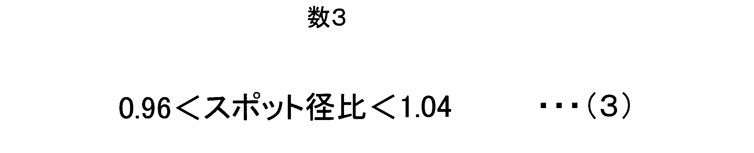
なお、本発明での光スポットは、

を満足する光スポット径となることを特徴としている。
ここで、
スポット径比=スポット径計算値/スポット径理論値、
スポット径理論値=0.82×λ/NA0、
で定義している。
ここで、
スポット径比=スポット径計算値/スポット径理論値、
スポット径理論値=0.82×λ/NA0、
で定義している。
さらに、焦点距離fは

とすることが望ましい。1.15<fとすることが好ましい理由は、ワーキングディスタンスを確保することにある。
さらに、焦点距離fが短いということは、光ピックアップ対物レンズ6の第一面と第二面の曲率半径Rが小さくなり、結果としてコバ厚が薄くなる。コバ厚が薄くなると、コバが割れるなどの不具合が発生し、光ピックアップ対物レンズ6の取り付けが困難になる。
また、式(1)、(2)を同時に満たすような光ピックアップ対物レンズ6を設計することにより、カバー層厚みが0.075mmや0.1mmと異なる場合でも波面収差とスポット径が悪くならない光ピックアップ対物レンズ6の設計が可能となる
さらに、多層ディスク7のような、カバー層厚みが0.05mmから0.1mmと範囲が広く、情報記録面が3層以上の複数層形成されるディスク7においても波面収差とスポット径を劣化させることなく使用可能である。
本発明の光ピックアップ対物レンズは、複数の情報記録面をもつ光情報記録媒体に情報の記録及び再生を行う光ピックアップ装置に搭載される開口数0.84以上のプラスチック製の光ピックアップ対物レンズであって、当該光ピックアップ対物レンズは少なくとも一面が輪帯形状となっており、前記光ピックアップ対物レンズに、波長が380nm~430nmの青紫色レーザー光が入射して、接線角θ(h)と近似接線角φと規格化光線高さhとが以下の条件式を満足することを特徴とする。

但し、接線角θ(h)は、光線高さhの時の接線角(°)、近似接線角φは、接線角θ(h)の各点を線形近似した時のh=1の時の角度(°)の値、規格化光線高さhは、レンズ有効径の最外周を1に規格化した値である。
本発明の光ピックアップ対物レンズは、更に、屈折率nと接線角θ(h=1)が、以下の式を満足することを特徴とする。

本発明の光ピックアップ対物レンズは、更に、スポット径比が、以下の式を満足することを特徴とする。
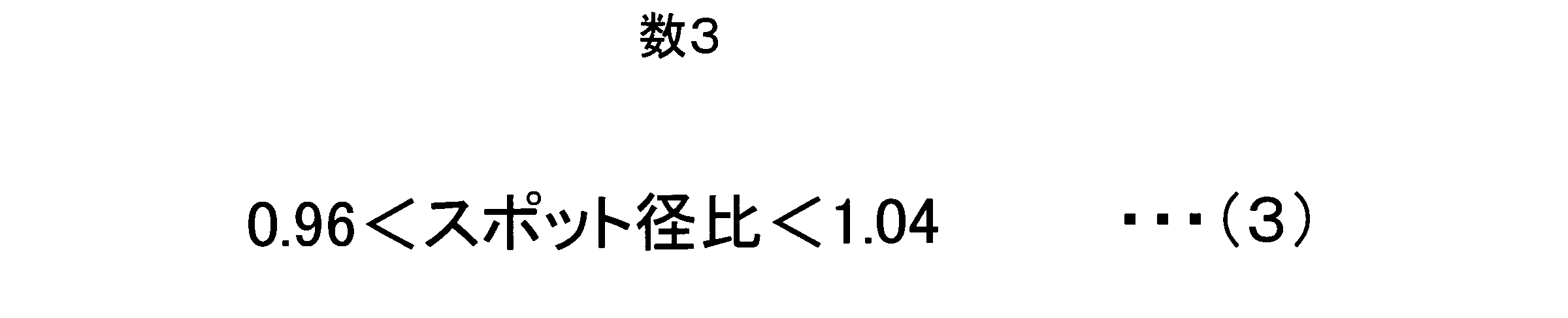
但し、スポット径比=スポット径計算値/スポット径理論値、(スポット径理論値=0.82×λ/NA0)、NA0は近軸での開口数であり、λは入射する光の波長である。
本発明の光ピックアップ対物レンズは、更に、焦点距離f(mm)が、以下の式を満足することを特徴とする。

また、本発明の光ピックアップ対物レンズは、3層以上の複数の情報記録面をもつ光情報記録媒体に情報の記録及び再生を行う光ピックアップ装置に搭載される開口数0.84以上のプラスチック製の光ピックアップ対物レンズであって、当該光ピックアップ対物レンズは少なくとも一面が輪帯形状となっており、前記光ピックアップ対物レンズに、波長が380nm~430nmの青紫色レーザー光が入射して、接線角θ(h)と近似接線角φと規格化光線高さhとが以下の条件式を満足することを特徴とする。

但し、規格化光線高さhは、レンズ有効径の最外周を1に規格化した値であり、接線角θ(h)は、規格化光線高さhの時の接線角(°)、近似接線角φは、接線角θ(h)の各点を線形近似した時のh=1の時の角度(°)の値である。
本発明の光ピックアップ装置は、上記の光ピックアップ対物レンズを搭載していることを特徴とする。
また、本発明の光ピックアップ装置は、カバー層厚みが3層以上であり、3個以上の複数の情報記録面を備えた情報記録媒体を記録再生することができる光ピックアップ装置であって、上記の光ピックアップ対物レンズを搭載していることを特徴とする。
本発明によれば、光ピックアップ対物レンズの波面収差、光スポットをともに向上することが出来る。
次に、本発明の実施の形態にかかわる光ピックアップ装置について説明する。図8は、ブルーレイディスク(BD)7に対して適切に情報の記録、再生をおこなえる本実施の形態の光ピックアップ装置PU1の構成を概略的に示す図である。かかる光ピックアップ装置PU1は、光情報記録再生装置に搭載できる。
光ピックアップ装置PU1は、BD7に対して情報の記録再生を行う場合に使用され380nm以上のレーザー光束を発光する。レーザー光の光路上にビームスプリッタ2が設けられている。ビームスプリッタ2及び1/4波長板3を透過することにより、円偏光に変換される。
1/4波長板3から出射されたレーザー光の光路上にカップリングレンズ4が設けられている。カップリングレンズ4は、プラスチック素材またはガラス素材から形成され、カップリングレンズ4がアクチュエータにより光軸方向を動く事で適切な角度をもった光に広げられる。適切な角度とは一般的にディスク7に到達した時の波面収差が一番小さくなるように設定された角度である。
このようにして、カップリングレンズ4を通過した光は、絞り5を通過した後、輪帯構造9をもった光ピックアップ対物レンズ6に入射される。この時、本発明によれば、多層ディスク7でのカバー層厚みが変化した場合にも高次球面収差を発生させないよう設計されている。
このように、適切なスポットを持った開口数NA0.85の光とした後、光ディスク7の情報記録面に入射することになる。
光ディスク7の情報記録面で反射されたレーザー光は、光ピックアップ対物レンズ6を介して光検出器8に入射し、検出される。光検出器8は、当該レーザー光を検出し、光電変換して出力信号を出力する。そして、光検出器8の出力信号に基づいて、フォーカスエラー信号、トラックエラー信号、再生信号などを生成する。また、当該フォーカスエラー信号、トラックエラー信号、再生信号などを用いて、光ディスク7の記録及び/又は再生を行う。
次に、本発明にかかる実施例1について説明する。図10に示す表に、実施例1にかかる光ピックアップ装置PU1の光ピックアップ対物レンズ6の屈折率、中心厚、輪帯9の幅、輪帯9の段差量、非球面係数、曲率を示す。図10に示す係数は後述する数式(5)の係数として用いられる。したがって、実施例1にかかる光ピックアップ対物レンズ6の面形状は図10に示す係数を用いた数式(5)で表現される。

但し、Zjは非球面形状、hは光軸からの光線の高さ、Cは曲率、Kはコーニック係数、A4、A6、A8、A10、A12、A14、A16はそれぞれ、4次から16次までの非球面係数である。なお、C=1/R(Rは曲率半径)である。
図11に本発明の実施例1の結果を示す。屈折率は1.50と低い場合の例となっている。実施例1はカバー層厚み0.075mmでの高次球面収差は6.5mλrms、カバー層厚み0.1mmでの高次球面収差は6.7mλrmsとなっており、高次球面収差は十分小さくなっている。
また、カバー層厚み0.075mmでのスポット径は0.393μm、カバー層厚み0.0875mmでのスポット径は0.394μm、0.1mmでのスポット径は0.395μmとなっている。スポット径の理論値は0.391μmであるので、スポット径も十分小さくなっていることが分かる。
本発明の実施例1では、光ディスク7の情報記録面を、カバー層厚み0.075mm、0.0875mm、0.1mmの位置に設けられた3層のブルーレイ光ディスクにおいても、各情報記録面に、高次球面収差は十分小さく、また、スポット径も十分小さく、良好に、ブルーレイのレーザー光を収束することができる。
また、光ディスク7の情報記録面を、カバー層厚み0.075mm、0.1mmの位置に設けられた2層のブルーレイ光ディスクに適用し、中間の0.0875mmの位置に焦点を合わせる場合にも、焦点の位置が変動しても、各情報記録面において、波面収差は十分小さく、また、スポット径も十分小さく、良好に、ブルーレイのレーザー光を収束することができる。
このような設計では、図11に示す通り、光線高さhと接線角θ(h)は、

を満たすような直線となるよう設計されている。
さらに、この時の有効径での接線角θ(h=1)は73.687度(°)であり、屈折率nは1.50なので、屈折率n*接線角θ(h=1)は110.5305となり、

を満足する光ピックアップ対物レンズとなっている。
図12は、実施例1にかかるR2面(光ピックアップ対物レンズの出射面)側の規格化光線高さと接線角の関係を表した図である。図12の横軸は、図8のB点で示されるR2面(光ピックアップ対物レンズの出射面)側の規格化光線高さ1に対する相対的な規格化光線高さを示し、図12の縦軸はR2面の接線角を示している。
実施例1においては、R2の接線角θ(i)は、光ピックアップレンズ6の中央部から、規格化光線高さが増加するにつれて増加し、その後、光ピックアップレンズ6のレンズ周辺に向かってなだらかに接線角θ(i)が減少していく曲線となる。
次に、本発明にかかる実施例2について説明する。図13に示す表に、実施例2にかかる光ピックアップ装置PU1の光ピックアップ対物レンズ6の屈折率、中心厚、輪帯9の幅、輪帯9の段差量、非球面係数、曲率を示す。図13に示す係数は上述の数式(5)の係数として用いられる。したがって、実施例2にかかる光ピックアップ対物レンズ6の面形状は図13に示す係数を用いた数式(5)で表現される。
図14に実施例2の結果を示す。実施例2はカバー層厚み0.075mmでの高次球面収差は5.1mλrms、0.1mmでの高次球面収差は4.4mλrmsとなっており、高次球面収差は十分小さくなっている。
また、カバー層厚み0.075mmでのスポット径は0.393μm、0.1mmでのスポット径は0.395μmとなっている。スポット径の理論値は0.391μmであるので、スポット径も十分小さくなっていることが分かる。
本発明の実施例2では、光ディスク7の情報記録面を、カバー層厚み0.075mm、0.0875mm、0.1mmの位置に設けられた3層のブルーレイ光ディスクにおいても、各情報記録面に、高次球面収差は十分小さく、また、スポット径も十分小さく、良好に、ブルーレイのレーザー光を収束することができる。
また、光ディスク7の情報記録面を、カバー層厚み0.075mm、0.1mmの位置に設けられた2層のブルーレイ光ディスクに適用し、中間の0.0875mmの位置に焦点を合わせる場合にも、焦点の位置が変動しても、各情報記録面において、高次球面収差は十分小さく、また、スポット径も十分小さく、良好に、ブルーレイのレーザー光を収束することができる。
本実施例でも図15に示す通り、光線高さhと接線角θ(h)は、

を満たすような直線となるように設計されている。
さらに、この時の有効径での接線角θ(h=1)は72.744度であり、屈折率nは1.52なので、接線角×屈折率は110.571となり、

を満足するレンズとなっている。
図15は、実施例2にかかるR2面(光ピックアップ対物レンズの出射面)側の規格化光線高さと接線角の関係を表した図である。図15の横軸は、図8のB点で示されるR2面(光ピックアップ対物レンズの出射面)側の規格化光線高さ1に対する相対的な規格化光線高さを示し、図15の縦軸はR2面の接線角を示している。
実施例2においても、R2の接線角θ(i)は、光ピックアップレンズ6の中央部から、規格化光線高さが増加するにつれて増加し、その後、光ピックアップレンズ6のレンズ周辺に向かってなだらかに接線角θ(i)が減少していく曲線となる。
次に、本発明にかかる実施例3について説明する。本実施例は多層ディスクに使用されるものであり、カバー層厚みは0.05mmから0.1mmの範囲である。本実施例ではカバー層厚み0.05mmから0.1mmの中間カバー層厚みである0.075mmで設計されている。
図16に示す表に、実施例3にかかる光ピックアップ装置PU1の光ピックアップ対物レンズ6の屈折率、中心厚、輪帯9の幅、輪帯9の段差量、非球面係数、曲率を示す。図16に示す係数は後述する数式(5)の係数として用いられる。したがって、実施例3にかかる光ピックアップ対物レンズ6の面形状は図16に示す係数を用いた数式(5)で表現される。
図17に実施例3の結果を示す。実施例3では、カバー層厚み0.05mmでの高次球面収差は12.6mλrms、0.0625mmでの波面収差高次球面収差は5.6mλrms、0.075mmでの高次球面収差は0.0mλrms、0.0875mmでの高次球面収差は4.8mλrms、0.1mmでの高次球面収差は9.3mλrmsとなっており、高次球面収差は十分小さくなっている。
カバー層厚み0.05mmでのスポット径は0.393μm、0.0625mmでのスポット径は0.394μm、0.075mmでのスポット径は0.394μm、0.0875mmでのスポット径は0.396μm、0.1mmでのスポット径は0.396μmとなっている。スポット径の理論値は0.391μmであるので、スポット径も十分小さくなっていることが分かる。
本発明の実施例3では、光ディスク7の情報記録面を、カバー層厚み0.05mm、0.0625mm、0.075mm、0.0875mm、0.1mmの位置に設けられた5層のブルーレイ光ディスクにおいても、各情報記録面に、高次球面収差は十分小さく、また、スポット径も十分小さく、良好に、ブルーレイのレーザー光を収束することができる。
また、光ディスク7の情報記録面を、カバー層厚み0.05mm、0.075mm、0.1mmの位置に設けられた3層のブルーレイ光ディスクに適用し、中間の0.0625mmと0.0875mmの位置に焦点を合わせる場合にも、焦点の位置が変動しても、各情報記録面において、高次球面収差は十分小さく、また、スポット径も十分小さく、良好に、ブルーレイのレーザー光を収束することができる。
本実施例でも図18に示す通り、光線高さhと接線角θ(h)は、

を満たすような直線となるよう設計されている。
さらに、この時の有効径での接線角θ(h=1)は72.668度であり、屈折率nは1.52なので、接線角×屈折率は110.455となり

を満足するレンズとなっている。
図18は、実施例3にかかるR2面(光ピックアップ対物レンズの出射面)側の規格化光線高さと接線角の関係を表した図である。図18の横軸は、図8のB点で示されるR2面(光ピックアップ対物レンズの出射面)側の規格化光線高さ1に対する相対的な規格化光線高さを示し、図18の縦軸はR2面の接線角を示している。
実施例3においても、R2の接線角θ(i)は、光ピックアップレンズ6の中央部から、規格化光線高さが増加するにつれて増加し、その後、光ピックアップレンズ6のレンズ周辺に向かってなだらか接線角θ(i)が減少していく曲線となる。
次に、本発明にかかる実施例4について説明する。図19に示す表に、実施例4にかかる光ピックアップ装置PU1の光ピックアップ対物レンズ6の屈折率、中心厚、輪帯9の幅、輪帯9の段差量、非球面係数、曲率を示す。図19に示す係数は上述の数式(5)の係数として用いられる。したがって、実施例4にかかる光ピックアップ対物レンズ6の面形状は図19に示す係数を用いた数式(5)で表現される。
図20に実施例4の結果を示す。実施例4は従来例1と同じ有効径、焦点距離f、NA、屈折率となっており、実施例4と等価の設計となっている。実施例4はカバー層厚み0.075mmでの高次球面収差は3.6mλrms、0.1mmでの高次球面収差は3.2mλrmsとなっており、更に多層用と仮定して設計カバー層0.0875から0.025mmずれた0.0625mmと0.1125mmを計算してみると、0.0625mmは8.2mλrms、0.1125mmは6.3mλrmsとなっており、平均値は7.25mλrmsである。前記平均値を従来例1と比べると5.35mλrms小さくなっていることが分かる。
カバー層厚み0.0625mmでのスポット径は0.391μm、0.075mmでのスポット径は0.391μm、0.1mmでのスポット径は0.393μm、0.1125mmでのスポット径は0.394μm、となっている。スポット径の理論値は0.391μmであるので、スポット径も十分小さくなっていることが分かる。
本実施例でも図21に示す通り、光線高さhと接線角θ(h)は、

を満たすような直線となるよう設計されている。
さらに、この時の有効径での接線角θ(h=1)は70.855度であり、屈折率は1.56なので、接線角×屈折率は109.534となり

を満足するレンズとなっている。
図21は、実施例4にかかるR2面(光ピックアップ対物レンズの出射面)側の規格化光線高さと接線角の関係を表した図である。図21の横軸は、図8のB点で示されるR2面(光ピックアップ対物レンズの出射面)側の規格化光線高さ1に対する相対的な規格化光線高さを示し、図21の縦軸はR2面の接線角を示している。
実施例4においても、R2の接線角θ(i)は、光ピックアップレンズ6の中央部から、規格化光線高さが増加するにつれて増加し、その後、光ピックアップレンズ6のレンズ周辺に向かってなだらかに接線角θ(i)が減少していく曲線となる。
次に、本発明にかかる実施例5について説明する。図22に示す表に、実施例5にかかる光ピックアップ装置PU1の光ピックアップ対物レンズ6の屈折率、中心厚、輪帯9の幅、輪帯9の段差量、非球面係数、曲率を示す。図22に示す係数は上述の数式(5)の係数として用いられる。したがって、実施例4にかかる光ピックアップ対物レンズ6の面形状は図22に示す係数を用いた数式(5)で表現される。
図23に実施例5の結果を示す。実施例5は従来例2と同じ有効径、焦点距離f、NA、屈折率となっており、実施例4と等価の設計となっている。
実施例5はカバー層厚み0.075mmでの高次球面収差は4.9mλrms、0.1mmでの高次球面収差は5.5mλrmsとなっており、更に多層用と仮定して設計カバー層0.0875から0.025mmずれた0.0625mmと0.1125mmを計算してみると、0.0625mmは9.1mλrms、0.1125mmは11.7mλrmsとなっており、平均値は10.4mλrmsである。
前記平均値を従来例2と比べると3.7mλrms小さくなっていることが分かる。カバー層厚み0.0625mmでのスポット径は0.391μm、0.075mmでのスポット径は0.392μm、0.1mmでのスポット径は0.392μm、0.1125mmでのスポット径は0.393μm、となっている。スポット径の理論値は0.391μmであるので、スポット径も十分小さくなっていることが分かる。
本実施例でも図24に示す通り、光線高さhと接線角θ(h)は、

を満たすような直線となるよう設計されている。
さらに、この時の有効径での接線角θ(h=1)は70.984度であり、屈折率は1.56なので、接線角×屈折率は110.735となり

を満足するレンズとなっている。
図24は、実施例5にかかるR2面(光ピックアップ対物レンズの出射面)側の規格化光線高さと接線角の関係を表した図である。図24の横軸は、図8のB点で示されるR2面(光ピックアップ対物レンズの出射面)側の規格化光線高さ1に対する相対的な規格化光線高さを示し、図24の縦軸はR2面の接線角を示している。
実施例5においても、R2の接戦角θ(i)は、光ピックアップレンズ6の中央部から、規格化光線高さが増加するにつれて増加し、その後、光ピックアップレンズ6のレンズ周辺に向かってなだらかに接線角θ(i)が減少していく曲線となる。
1 光ピックアップ装置PU
2 ビームスプリッタ
3 1/4波長板
4 カップリングレンズ
5 絞り
6 光ピックアップ対物レンズ
7 多層ディスク
8 光検出器
9 輪帯
2 ビームスプリッタ
3 1/4波長板
4 カップリングレンズ
5 絞り
6 光ピックアップ対物レンズ
7 多層ディスク
8 光検出器
9 輪帯
Claims (7)
- 複数の情報記録面をもつ光情報記録媒体に情報の記録及び再生を行う光ピックアップ装置に搭載される開口数0.84以上のプラスチック製の光ピックアップ対物レンズであって、当該光ピックアップ対物レンズは少なくとも一面が輪帯形状となっており、前記光ピックアップ対物レンズに、波長が380nm~430nmの青紫色レーザー光が入射して、接線角θ(h)と近似接線角φと規格化光線高さhとが以下の条件式を満足することを特徴とする光ピックアップ対物レンズ。

- 屈折率nと接線角θ(h=1)が、以下の式を満足することを特徴とする請求項1記載の光ピックアップ対物レンズ。

- スポット径比が、以下の式を満足することを特徴とする請求項2記載の光ピックアップ対物レンズ。
- 焦点距離f(mm)が、以下の式を満足することを特徴とする請求項3記載の光ピックアップ対物レンズ。

- 3層以上の複数の情報記録面をもつ光情報記録媒体に情報の記録及び再生を行う光ピックアップ装置に搭載される開口数0.84以上のプラスチック製の光ピックアップ対物レンズであって、当該光ピックアップ対物レンズは少なくとも一面が輪帯形状となっており、前記光ピックアップ対物レンズに、波長が380nm~430nmの青紫色レーザー光が入射して、接線角θ(h)と近似接線角φと規格化光線高さhとが以下の条件式を満足することを特徴とする光ピックアップ対物レンズ。

- 請求項1ないし5のいずれかの請求項に記載の光ピックアップ対物レンズを搭載していることを特徴とする光ピックアップ装置。
- カバー層厚みが3層以上であり、3個以上の複数の情報記録面を備えた情報記録媒体を記録再生することができる光ピックアップ装置であって、請求項1ないし5のいずれかの請求項に記載の光ピックアップ対物レンズを搭載していることを特徴とする光ピックアップ装置。
Priority Applications (1)
| Application Number | Priority Date | Filing Date | Title |
|---|---|---|---|
| CN201180033357.4A CN102971791B (zh) | 2010-07-07 | 2011-06-17 | 光拾波器物镜和光拾波器装置 |
Applications Claiming Priority (2)
| Application Number | Priority Date | Filing Date | Title |
|---|---|---|---|
| JP2010-154943 | 2010-07-07 | ||
| JP2010154943A JP5683150B2 (ja) | 2010-07-07 | 2010-07-07 | 光ピックアップ対物レンズ及び光ピックアップ装置 |
Publications (1)
| Publication Number | Publication Date |
|---|---|
| WO2012005102A1 true WO2012005102A1 (ja) | 2012-01-12 |
Family
ID=45441088
Family Applications (1)
| Application Number | Title | Priority Date | Filing Date |
|---|---|---|---|
| PCT/JP2011/063962 Ceased WO2012005102A1 (ja) | 2010-07-07 | 2011-06-17 | 光ピックアップ対物レンズ及び光ピックアップ装置 |
Country Status (3)
| Country | Link |
|---|---|
| JP (1) | JP5683150B2 (ja) |
| CN (1) | CN102971791B (ja) |
| WO (1) | WO2012005102A1 (ja) |
Families Citing this family (1)
| Publication number | Priority date | Publication date | Assignee | Title |
|---|---|---|---|---|
| JP6600396B2 (ja) * | 2018-08-30 | 2019-10-30 | マクセル株式会社 | 位相フィルタ、撮像光学系、及び撮像システム |
Citations (2)
| Publication number | Priority date | Publication date | Assignee | Title |
|---|---|---|---|---|
| JP2010080040A (ja) * | 2008-04-10 | 2010-04-08 | Hitachi Maxell Ltd | 光ピックアップ対物レンズ、光ピックアップ装置及び光ディスク装置 |
| JP2010108531A (ja) * | 2008-10-28 | 2010-05-13 | Sony Corp | 対物レンズ、これを用いた光学ピックアップ装置、光記録再生装置及び収差補正方法 |
Family Cites Families (1)
| Publication number | Priority date | Publication date | Assignee | Title |
|---|---|---|---|---|
| ATE497239T1 (de) * | 2001-07-11 | 2011-02-15 | Konica Minolta Opto Inc | Optisches korrekturelement für aberration, optisches system, optisches abtastgerät und vorrichtung zur aufzeichnung und wiedergabe |
-
2010
- 2010-07-07 JP JP2010154943A patent/JP5683150B2/ja not_active Expired - Fee Related
-
2011
- 2011-06-17 CN CN201180033357.4A patent/CN102971791B/zh not_active Expired - Fee Related
- 2011-06-17 WO PCT/JP2011/063962 patent/WO2012005102A1/ja not_active Ceased
Patent Citations (2)
| Publication number | Priority date | Publication date | Assignee | Title |
|---|---|---|---|---|
| JP2010080040A (ja) * | 2008-04-10 | 2010-04-08 | Hitachi Maxell Ltd | 光ピックアップ対物レンズ、光ピックアップ装置及び光ディスク装置 |
| JP2010108531A (ja) * | 2008-10-28 | 2010-05-13 | Sony Corp | 対物レンズ、これを用いた光学ピックアップ装置、光記録再生装置及び収差補正方法 |
Also Published As
| Publication number | Publication date |
|---|---|
| CN102971791B (zh) | 2015-07-15 |
| JP5683150B2 (ja) | 2015-03-11 |
| JP2012018721A (ja) | 2012-01-26 |
| CN102971791A (zh) | 2013-03-13 |
Similar Documents
| Publication | Publication Date | Title |
|---|---|---|
| JP2011014236A (ja) | 光ピックアップ装置用の対物光学系、光ピックアップ装置、光情報記録媒体のドライブ装置、集光レンズ、及び光路合成素子 | |
| JP2009277311A (ja) | 対物レンズ、光ピックアップ装置、光記録・再生装置 | |
| JP2003287675A (ja) | 集光光学系、光ピックアップ装置、記録・再生装置、収差補正素子及び対物レンズ | |
| US7924685B2 (en) | Objective lens | |
| JP5013117B2 (ja) | 光ピックアップ装置及び光ピックアップ装置用の対物光学素子 | |
| JP2009252309A (ja) | 光情報記録再生装置用対物レンズ、および光情報記録再生装置 | |
| JP2001249273A (ja) | 光ヘッド用対物レンズ | |
| JPWO2005083694A1 (ja) | 対物光学系、光ピックアップ装置及び光情報記録再生装置 | |
| US8009544B2 (en) | Objective lens, optical pickup device having the same, and recording and/or reproducing apparatus for optical recording medium, equipped with the optical pickup device | |
| JP2001194581A (ja) | 対物レンズ及び光ピックアップ装置 | |
| JP5683150B2 (ja) | 光ピックアップ対物レンズ及び光ピックアップ装置 | |
| JP5199835B2 (ja) | 光情報記録再生装置用対物レンズ、および光情報記録再生装置 | |
| CN102054491B (zh) | 物镜、光学拾取器以及光盘装置 | |
| US8064319B2 (en) | Objective lens, optical pickup device having the same, and recording and/or reproducing apparatus for optical recording medium, equipped with the optical pickup device | |
| US20090129242A1 (en) | Objective lens, optical pickup device having the same, and recording and/or reproducing apparatus for optical recording medium, equipped with the optical pickup device | |
| JP2013206496A (ja) | 光ピックアップ装置及び対物レンズ | |
| JP2003279850A (ja) | 収差補正素子、光ピックアップ装置及び記録再生装置 | |
| JP2010040073A (ja) | 光ピックアップ光学系 | |
| JP5466620B2 (ja) | 対物レンズ | |
| US20130003192A1 (en) | Method for designing objective lens and objective lens | |
| JP2007087479A (ja) | 対物光学系及び光ピックアップ装置 | |
| JP2009217907A (ja) | 光ピックアップ光学系及び対物レンズ | |
| JP2008117473A (ja) | 対物レンズ光学系、光束分割素子及び光ピックアップ光学系 | |
| US20080181090A1 (en) | Objective lens optical system and light beam splitting element | |
| JP2008117472A (ja) | 対物レンズ光学系、光束分割素子及び光ピックアップ光学系 |
Legal Events
| Date | Code | Title | Description |
|---|---|---|---|
| WWE | Wipo information: entry into national phase |
Ref document number: 201180033357.4 Country of ref document: CN |
|
| 121 | Ep: the epo has been informed by wipo that ep was designated in this application |
Ref document number: 11803438 Country of ref document: EP Kind code of ref document: A1 |
|
| NENP | Non-entry into the national phase |
Ref country code: DE |
|
| 122 | Ep: pct application non-entry in european phase |
Ref document number: 11803438 Country of ref document: EP Kind code of ref document: A1 |