US8064319B2 - Objective lens, optical pickup device having the same, and recording and/or reproducing apparatus for optical recording medium, equipped with the optical pickup device - Google Patents
Objective lens, optical pickup device having the same, and recording and/or reproducing apparatus for optical recording medium, equipped with the optical pickup device Download PDFInfo
- Publication number
- US8064319B2 US8064319B2 US12/273,139 US27313908A US8064319B2 US 8064319 B2 US8064319 B2 US 8064319B2 US 27313908 A US27313908 A US 27313908A US 8064319 B2 US8064319 B2 US 8064319B2
- Authority
- US
- United States
- Prior art keywords
- objective lens
- recording medium
- optical recording
- optical
- denotes
- Prior art date
- Legal status (The legal status is an assumption and is not a legal conclusion. Google has not performed a legal analysis and makes no representation as to the accuracy of the status listed.)
- Expired - Fee Related, expires
Links
Images


Classifications
-
- G—PHYSICS
- G02—OPTICS
- G02B—OPTICAL ELEMENTS, SYSTEMS OR APPARATUS
- G02B27/00—Optical systems or apparatus not provided for by any of the groups G02B1/00 - G02B26/00, G02B30/00
- G02B27/0025—Optical systems or apparatus not provided for by any of the groups G02B1/00 - G02B26/00, G02B30/00 for optical correction, e.g. distorsion, aberration
- G02B27/0031—Optical systems or apparatus not provided for by any of the groups G02B1/00 - G02B26/00, G02B30/00 for optical correction, e.g. distorsion, aberration for scanning purposes
-
- G—PHYSICS
- G11—INFORMATION STORAGE
- G11B—INFORMATION STORAGE BASED ON RELATIVE MOVEMENT BETWEEN RECORD CARRIER AND TRANSDUCER
- G11B7/00—Recording or reproducing by optical means, e.g. recording using a thermal beam of optical radiation by modifying optical properties or the physical structure, reproducing using an optical beam at lower power by sensing optical properties; Record carriers therefor
- G11B7/12—Heads, e.g. forming of the optical beam spot or modulation of the optical beam
- G11B7/135—Means for guiding the beam from the source to the record carrier or from the record carrier to the detector
- G11B7/1372—Lenses
- G11B7/1374—Objective lenses
Definitions
- the invention relates to an objective lens capable of efficiently converging used light onto an optical recording medium when information is recorded or reproduced, an optical pickup device and a recording and/or reproducing apparatus for the optical recoding medium.
- the invention relates to an objective lens for used in recording/reproducing a high density optical recording medium with blue light having a short wavelength, an optical pickup device, and a recording and/or reproducing apparatus for the optical recording medium.
- the BD For the BD, light which is emitted from a semiconductor laser (for example, emitting laser light having a wavelength of 405 nm) having a short wavelength light output is used as irradiation light, and a numerical aperture is increased to be equal to or greater than 0.7.
- the numerical aperture and a thickness of a protection layer for example, the numerical aperture (NA) is 0.85, and the thickness of the protection layer is 0.1 mm are set quietly different from those of DVD and CD.
- Another way for achieving high density is to further increase the numerical aperture of the objective lens.
- a lens having a large numerical aperture hereinafter, it is referred to as a “high NA”
- a single lens structure is effective to solve problems such as an increase in process number during assembly, deterioration in production efficiency, and an increase in cost.
- the high NA objective lens it is important to prevent deterioration in aberration. Therefore, it is important to satisfactorily correct various aberrations by providing an aspheric surface or the like.
- an objective lens for use in recording/reproducing an optical recording medium has a peculiar shape, that is, a convex surface which has a large curvature and is directed to a light source.
- a shape of the lens has great influence on not only a spherical aberration but also various aberrations.
- JP 2003-5032 A (corresponding to U.S. Pat. No. 7,110,344), a conditional expression relating to a sag amount is defined, and a value determined by the conditional expression is set in a predetermined allowable range, thereby preventing deterioration in various aberrations of the high NA lens.
- an on-axis thickness d is set to be in a predetermined range which is defined based on a relation between the thickness d and a focal length f, and so excellent image height characteristic are obtained (see JP 2001-324673 A (corresponding to U.S. Pat. No. 6,411,442) and JP 2003-5032 A).
- the invention has been made in consideration of this situation, and to provides an objective lens capable of satisfactorily correcting a spherical aberration, obtaining excellent image height characteristic, satisfactorily securing an operating distance and achieving reduction in weight of the lens even when the objective lens for recording information into or reproducing information from an optical recording medium is used as a high NA single lens element capable of converging short wavelength light onto an optical recording layer.
- the invention also provides an optical pickup device and a recording and/or reproducing apparatus for the optical recording medium.
- an objective lens converges used light on a desired position of an optical recording medium which information is recorded in and reproduced from.
- the objective lens consists a single lens element having at lest one aspheric surface.
- conditional expressions (1) to (3) are satisfied. 0.70 ⁇ NA ⁇ 0.98 (1) 0.70 ⁇ d/f ⁇ 1.40 (2) 0.48 ⁇ X ⁇ 0.55 (3)
- d denotes a thickness of the objective lens on an optical axis in mm
- f denotes a focal length of the objective lens in mm
- X is equal to (X1 ⁇ X2) ⁇ (n ⁇ 1)/(NA ⁇ f)
- conditional expression (4) 1.0 ⁇ A ⁇ 5.0 (4) where ⁇ A denotes the effective diameter of the light source side surface of the objective lens.
- conditional expression (5) is satisfied 0.25 ⁇ Y ⁇ 0.65 (5) where Y is equal to R1/(n ⁇ f), and
- the wavelength of the used light may be 405.0 ⁇ 5.0 nm.
- the wavelength of the used light may be 405.0 ⁇ 5.0 nm
- the numerical aperture NA may be 0.85
- a thickness of a protection layer of the optical recording medium may be 0.1 mm.
- the wavelength of the used light is 405.0 ⁇ 5.0 nm, that the numerical aperture NA is 0.85, that aberration is minimized at a position being distant t1 mm from a surface of the optical recording medium to an inside of the optical recording medium, and that the following conditional expression (6) is satisfied. 0.075 ⁇ t1 ⁇ 0.1 (6)
- an optical pickup device includes the objective lens set forth above and an actuator that performs a focusing operation of the objective lens and a tracking operation of the objective lens.
- a recording and/or reproducing apparatus for an optical recording medium includes the optical pickup device set forth above.
- the objective lens is configured to satisfy the conditional expression (1), and to have the large numerical aperture, that is, 0.70 to 0.98. Therefore, it is possible to decrease a diameter of a spot focused on the optical recording medium. Thus, it is possible to record information with higher density even on an optical recording medium which will be developed in future or reproduce information recorded with higher density therefrom.
- the at least one surface of the objective lens has an aspheric surface. Therefore, it is possible to satisfactorily correct various aberrations such as a spherical aberration and a comatic aberration.
- the objective lens consists of the single lens element, alignment adjustment during assembly is not required, and production efficiency and reduce costs can be achieved.
- the objective lens is configured to satisfy the conditional expression (2).
- a condition for obtaining an excellent image height characteristic is defined by the focal length f and the thickness d on the optical axis of the lens is set in a predetermined range.
- the objective lens is configured to satisfy the conditional expression (3) and to define a difference between a sag amount of the light source side surface and a sag amount of the optical recording medium side surface to be in a predetermined range.
- the NA is set to be larger than 0.48, which is the lower limit of X defined by the conditional expression (3). Thereby, it is possible to surely prevent a spherical aberration of the marginal ray from being excessively corrected.
- the NA is set to be smaller than 0.55, which is the upper limit of X. Thereby, it is possible to surely prevent the spherical aberration of the marginal ray from being insufficiently corrected.
- the optical pickup device and the recording and/or reproducing apparatus include the objective lens described above. Therefore, it is possible to obtain the same effect as the objective lens.
- FIG. 1 is a section diagram schematically illustrating an objective lens according to Example 1 of the invention.
- FIG. 2 is a section diagram schematically illustrating an objective lens according to Example 2 of the invention.
- FIG. 3 is a section diagram schematically illustrating an objective lens according to Example 3 of the invention.
- FIG. 4 is a section diagram schematically illustrating an objective lens according to Example 4 of the invention.
- FIG. 5 is a section diagram schematically illustrating an objective lens according to Example 5 of the invention.
- FIG. 6 is a section diagram schematically illustrating an objective lens according to Example 6 of the invention.
- FIG. 7 is a schematic diagram illustrating an optical pickup device (an optical recording medium recording and/or reproducing apparatus) equipped with the objective lens according to an embodiment of the invention.
- FIG. 8 is a diagram illustrating wavefront aberration in the objective lens according to Example 1 of the invention.
- FIG. 9 is a diagram illustrating wavefront aberration in the objective lens according to Example 2 of the invention.
- FIG. 10 is a diagram illustrating wavefront aberration in the objective lens according to Example 3 of the invention.
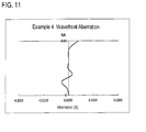
- FIG. 11 is a diagram illustrating wavefront aberration in the objective lens according to Example 4 of the invention.
- FIG. 12 is a diagram illustrating wavefront aberration in the objective lens according to Example 5 of the invention.
- FIG. 13 is a diagram illustrating wavefront aberration in the objective lens according to Example 6 of the invention.
- FIG. 1 is a schematic diagram showing a representative example of an objective lens according to Example 1, in order to explain the configuration of the objective lens for an optical recording medium according to an embodiment of the invention.
- FIG. 7 is a diagram showing an optical pickup device and the partial configuration of a recording and/or reproducing apparatus for the optical recording medium, and is one exemplary configuration having the objective lens according to this embodiment.
- laser light 11 output from a semiconductor laser 1 is substantially collimated via a half mirror 6 and a collimator lens 7 , and is incident on an objective lens 8 for an optical recording medium.
- the laser light 11 is converted into convergent light by the objective lens 8 , and is applied onto an optical recording layer 10 of an optical recording medium 9 (hereinafter, referred to as a blu-ray disc).
- the objective lens 8 performs tracking and focusing by using a servo mechanism including an actuator (which is not shown in the figure).
- the objective lens 8 is configured to satisfy the following three conditional expressions (1) to (3). 0.70 ⁇ NA ⁇ 0.98 (1) 0.70 ⁇ d/f ⁇ 1.40 (2) 0.48 ⁇ X ⁇ 0.55 (3) where
- NA denotes a numerical aperture of the objective lens 8 on the optical recording medium side
- d denotes a thickness (mm) of the objective lens 8 on an optical axis
- f denotes a focal length (mm) of the objective lens 8 .
- X is equal to (X1 ⁇ X2) ⁇ (n ⁇ 1)/(NA ⁇ f).
- n denotes a refractive index of the objective lens 8 at a wavelength of the used light.
- X1 denotes a distance (mm) in the optical axis direction between (a) a first tangential plane that is perpendicular to the optical axis and is tangent to a vertex of a light source side surface of the objective lens and (b) a most outside position within an effective diameter of the light source side surface (a position on the light source side surface on the marginal ray having NA is incident).
- X1 is defined so that a direction toward the optical recording medium from the first tangential plane serving as a reference point is a positive direction and that a direction toward the light source from the first tangential plane is a negative direction.
- X2 denotes a distance (mm) in the optical axis direction between (a) a second tangential plane that is perpendicular to the optical axis and is tangent to a vertex of (b) an optical recording medium side surface of the objective lens and a most outside position within an effective diameter of the optical recording medium side surface (a position on the optical recording medium side surface in which the marginal ray having NA is incident). Also, X2 is defined so that a direction toward the optical recording medium from the second tangential plane serving as a reference point is a positive direction and a direction toward the light source from the second tangential plane is a negative direction.
- the optical recording medium 9 conforms to the following standard.
- a numerical aperture NA 0.85 (which can be changed in the range of 0.7 ⁇ NA ⁇ 0.98).
- a wavelength ⁇ of used light 404.7 nm (which can be changed in the range of 405.0 ⁇ 5.0 nm, and for instance, 404.7 nm in Examples 1 to 3; 408.0 nm in Example 4; and 405.0 nm in Examples 5 and 6).
- a thickness t of a protection layer 0.1 mm (0.1 mm in Examples 1 to 4; and in Examples 5 and 6, the optical recording medium is a double layer disc, and when a thickness t of the protection layer is considered in view of a design for the double layer disc, 0.0875 mm which is a distance from a surface to a position where aberration is minimized is used instead of the thickness of the actual protection layer).
- respective record layers are provided at distances of 0.075 mm and 0.100 mm from the disc surface.
- the objective lens for the double layer disc is configured so that aberration becomes better in the middle part (which is located at the distance of 0.0875 mm from the surface) between the two record layers.
- this embodiment of the invention does not exclude the case where the objective lens is used as an objective lens for recording/reproducing information into/from an optical recording medium using other short wavelength light such as a so-called AOD (HD-DVD) disc.
- the semiconductor laser 1 is a light source that outputs laser light of a blue wavelength region such as a wavelength of 404.7 nm for use in blu-ray discs.
- the collimator lens 7 is just schematically illustrated in FIG. 7 , but is not limited to one element configuration.
- the collimator lens 7 may include plural lens elements.
- a light flux output from the semiconductor laser 1 is incident on a light source side surface 8 a of the objective lens 8 in a state of parallel light flux.
- the objective lens 8 by refractive action of the objective lens 8 , it is possible to condense exit light flux from an optical recording medium side surface 8 b of the objective lens 8 onto the optical recording layer 10 , which can record or reproduce information, of the optical recording medium 9 .
- the optical recording layer 10 pits (each of which is not necessary to have a concave shape physically) which carry signal information are arranged in a track manner.
- the reflected light of the laser light 11 from the optical recording layer 10 is incident on the half mirror 6 via the objective lens 8 and the collimator lens 7 in a state where the light carries signal information, and passes through the half mirror 6 to be incident on a four-divided photo diode 13 .
- a light receiving amount of each of the four divided positions of the diode is obtained as an electric signal.
- a calculation device (not shown in the figure) performs predetermined calculation based on the light receiving amounts, and so it is possible to obtain data signals, an error signal for focusing and an error signal for tracking.
- the half mirror 6 is inserted to be inclined at an angle of 45 degrees with respect to an optical path of the returning light from the optical recording medium 9 . Therefore, the mirror 6 has the same function as a cylindrical lens, and the light beam transmitted through the half mirror 6 has astigmatism. Thereby, an amount of the focus error is determined in accordance with a shape of a beam spot of the returning light on the four-divided photo diode 13 . Also, by inserting a grating between the semiconductor laser 1 and the half mirror 6 , it becomes possible to detect a tracking error based on three beams.
- the objective lens 8 consists of a single lens element. As shown in FIG. 1 , the light source side surface of the lens is formed into a convex surface having a large curvature, and the optical recording medium side surface of the lens is formed into a surface having a small curvature (this surface is a concave surface in Examples 1 to 3 and 5, and is a convex surface in Examples 4 and 6). As described above, since the objective lens is formed of the single lens element, there is no need to adjust alignment between lenses, during assembly. As a result, it is possible to improve production efficiency and reduce costs.
- At least one surface of the objective lens 8 according to this embodiment is formed into an aspheric surface, and it is preferable that the both surfaces of the objective lens 8 be formed into aspheric surfaces.
- the aspheric surfaces be formed of aspheric surfaces which is rotationally symmetric and is represented by the following aspherical expression. By forming such a rotationally symmetric aspheric surface, it is possible to satisfactorily correct various aberrations such as spherical aberration and comatic aberration. Thus, it is possible to surely perform the focusing operation and satisfactorily perform the recording and reproducing operations.
- the shape of the aspheric surface formed on the objective lens 8 be appropriately set to converge light having a wavelength, which the aspheric surface acts, onto the optical recording layer 10 with aberrations being satisfactory corrected.
- Z denotes a length of a perpendicular drawn from a point on the aspheric surface, which is distant Y from the optical axis, to a tangential plane (plane vertical to the optical axis) passing through a vertex of the aspheric surface
- C denotes a curvature of the aspheric surface near the optical axis
- a mask 19 having an aperture corresponding to the numerical aperture of the optical recording medium 9 is disposed on the light source side of the objective lens 8 .
- the objective lens 8 may be made of plastic.
- Exemplary advantages of using a plastic material includes reduction in manufacturing costs, fast recording and reading enabled by reduction in weight, and improvement in processability of a mold.
- the objective lens 8 may be made of glass.
- Exemplary advantages of using a glass material include excellent resistance to temperature and humidity, and ease of acquisition of the material, which has less deterioration in transmittance even when short wavelength light is applied thereto for a long time.
- the objective lens 8 according to this embodiment satisfies the conditional expressions (1) to (3).
- the technical signification of this fact will be described.
- the conditional expression (1) defines a range of the numerical aperture (NA). That is, the conditional expression (1) is a factor required to achieve recording and reproducing with higher density. Specifically, by setting the numerical aperture (NA) to be large, that is, in the range of 0.70 to 0.98, it becomes possible to decrease a diameter of a spot condensed on the optical recording layer 10 of the optical recording medium 9 (the blu-ray disc). Thus, even for an optical recording medium which will be newly developed in future, it is possible to achieve recording and reproducing at higher density.
- the conditional expressions (2) and (3) are defined under the premise that the conditional expression (1) is satisfied.
- conditional expression (2) defines that d/f is in e greater than 0.70 and less than 1.40.
- conditional expression (2) By setting the conditional expression (2) to be in the above range, in the single lens clement having the large NA, satisfied are appropriate conditions of the thickness d of the lens on the optical axis and the focal length f thereof for achieving favorable image height characteristic.
- the thickness of the objective lens does not become excessively large, and components of various aberrations (spherical aberration component, comatic aberration component, and the like) at a time of assessing the image height characteristic with a wavefront aberration do not become excessively large.
- a weight of the lens is reduced, it is possible to drive an actuator for performing the focusing and tracking operations with a small electric power. Thus, it is also possible to sufficiently secure an operating distance.
- the objective lens is configured so as to satisfy the following conditional expression (2′) instead of the conditional expression (2), it is possible to obtain better effect than the effect, which is mentioned above and obtained by satisfying the conditional expression (2). 1.10 ⁇ d/f ⁇ 1.28 (2′).
- conditional expression (3) is defined to satisfactorily correct spherical aberration in the single lens element having the high NA of 0.70 to 0.98, and relates to a sag amount of the light source side surface and a sag amount of the optical recording medium side surface.
- the objective lens according to this embodiment satisfies the conditional expression (3), it is possible to improve spherical aberration not only in the high NA single lens for blu-ray discs but also even in a higher-NA single objective lens which will be developed in future.
- an absolute value of X1 is quite greater than an absolute value of X2. Therefore, a magnitude of X1 ⁇ X2 greatly depends on a magnitude of X1. Accordingly, excessive increase in a value of X technically means excessive increase in curvature of the light source side surface, and leads to deterioration in mold separation during molding of a lens.
- the upper limit of the conditional expression (3) is defined in consideration of a value at which the mold separation during molding does not deteriorate. Meanwhile, when X reaches or falls below the lower limit of the conditional expression (3), in the case of high NA, spherical aberration is excessively corrected. Accordingly, by satisfying the conditional expression (3), it is possible to perform better mold separation during molding while achieving excellent optical performance.
- ⁇ A denotes the effective diameter of the light source side surface of the objective lens 8 .
- conditional expression (5) serves as a conditional expression for satisfactorily correcting a comatic aberration component of the image height characteristic. If Y is out of the range of the conditional expression (5), an absolute value of quantity which does not satisfy a sine condition. Thus, it is hard to satisfactorily correct the comatic aberration component of the image height characteristic.
- conditional expression (6) 0.075 ⁇ t1 ⁇ 0.1 (6) where t1 denotes a distance from the lens side surface of the optical recording medium to a position inside the medium where aberration is minimized.
- conditional expression (6) serves as a conditional expression for forming a fine image on both of the record layer positions. If t1 is out of the range of the conditional expression (6), although an image formed in one recording surface position of the two record layers is fine, an image formed in the other recording surface position deteriorates. Thus, imaging states of the two surfaces become greatly different.
- the optical pickup device may have an aberration correction unit for performing adjustment by shifting the lens in the optical axis direction.
- the conditional expression (6) also serves as a conditional expression for decreasing a load applied to the optical pickup device such as a lens shift distance for correcting aberration. Because of this, it is possible to shorten a time for aberration correction.
- the objective lens 8 according to Example 1 consists of a single lens element made of glass. As shown in FIG. 1 , the light source side surface 8 a is formed into a convex surface having a large curvature, and the optical recording medium side surface 8 b is formed into a concave surface (on the optical axis) having a small curvature.
- the both surfaces of the objective lens 8 according to Example 1 are formed into aspheric surfaces.
- the objective lens 8 is set to have a numerical aperture NA of 0.85 at the used light having a wavelength ⁇ of 404.7 nm, and satisfactory converges the light onto the optical recording layer 10 of the optical recording medium (blu-ray disc) 9 . Also, the thickness t of the protection layer of the optical recording medium 9 is set to be 0.1000 mm.
- Table 1 shows the following items as specific values of lens data of the objective lens 8 according to Example 1: the radius of curvature R (mm); the surface spacing D (mm); and the refractive index N at the light having the wavelength ⁇ . Furthermore, numerals corresponding to the radius of curvature R, the surface spacing D, and the refractive index N are arranged in ascending order from the light source side (this is similarly applied to Examples 2 to 6).
- Table 1 shows the aspherical coefficients C, K, and A 3 to A 20 of the rotationally symmetric aspheric surfaces of the objective lens 8 according to Example 1 (this is similarly applied to Examples 2 to 6).
- the lower part of the following Table 1 shows the following items at the used light having the wavelength ⁇ when the optical recording medium 9 is set: the following items are represented: the focal length f (mm); the back focal length bf (mm); the lens thickness d on the optical axis (mm); the protection layer thickness t (mm); and the effective diameters ⁇ A and ⁇ B (mm) of the respective surfaces (the light source side surface 8 a is referred to as a first surface, and the optical recording medium side surface 8 b is referred to as a second surface: the same is applied to the following Examples) of the objective lens 8 according to Example 1 (these are similarly applied to Examples 2 to 6).
- FIG. 8 shows a wavefront aberration curve of the objective lens 8 according to Example 1 at the used light having the wavelength ⁇ when the optical recording medium 9 is set.
- the objective lens 8 according to Example 1 satisfies all the conditional expressions (1) to (6) (including the conditional expression (2′)).
- the objective lens 8 according to Example 2 consists of a single lens element made of glass. As shown in FIG. 2 , the light source side surface 8 a is formed into a convex surface having a large curvature, and the optical recording medium side surface 8 b is formed into a concave surface (on the optical axis) having a small curvature.
- the both surfaces of the objective lens 8 according to Example 2 are formed into aspheric surfaces.
- the objective lens 8 is set to have a numerical aperture NA of 0.85 at the used light having a wavelength ⁇ of 404.7 nm, and satisfactory converges the light onto the optical recording layer 10 of the optical recording medium (blu-ray disc) 9 . Also, the thickness t of the protection layer of the optical recording medium 9 is set to be 0.1000 mm.
- Table 2 shows the following items as specific values of lens data of the objective lens 8 according to Example 2: the radius of curvature R (mm); the surface spacing D (mm); and the refractive index N at the light having the wavelength ⁇ .
- FIG. 9 shows a wavefront aberration curve of the objective lens 8 according to Example 2 at the used light having the wavelength ⁇ when the optical recording medium 9 is set.
- the objective lens 8 according to Example 2 satisfies all the conditional expressions (1) to (6).
- the objective lens 8 according to Example 3 consists of a single lens element made of glass. As shown in FIG. 3 , the light source side surface 8 a is formed into a convex surface having a large curvature, and the optical recording medium side surface 8 b is formed into a concave surface (on the optical axis) having a small curvature.
- the both surfaces of the objective lens 8 according to Example 3 are formed into aspheric surfaces.
- the objective lens 8 is set to have a numerical aperture NA of 0.85 at the used light having a wavelength ⁇ of 404.7 nm, and satisfactory converges the light onto the optical recording layer 10 of the optical recording medium (blu-ray disc) 9 . Also, the thickness t of the protection layer of the optical recording medium 9 is set to be 0.1000 mm.
- Table 3 shows the following items as specific values of lens data of the objective lens 8 according to Example 3: the radius of curvature R (mm); the surface spacing D (mm); and the refractive index N at the light having the wavelength ⁇ .
- FIG. 10 shows a wavefront aberration curve of the objective lens 8 according to Example 3 at the used light having the wavelength ⁇ when the optical recording medium 9 is set.
- the objective lens 8 according to Example 3 satisfies all the conditional expressions (1) to (6) (including the conditional expression (2′)).
- the objective lens 8 according to Example 4 consists of a single lens element made of plastic. As shown in FIG. 4 , the light source side surface 8 a is formed into a convex surface having a large curvature, and the optical recording medium side surface 8 b is formed into a convex surface (on the optical axis) having a small curvature.
- the both surfaces of the objective lens 8 according to Example 4 are formed into aspheric surfaces.
- the objective lens 8 is set to have a numerical aperture NA of 0.85 at the used light having a wavelength ⁇ of 408.0 nm, and satisfactory converges the light onto the optical recording layer 10 of the optical recording medium (blu-ray disc) 9 . Also, the thickness t of the protection layer of the optical recording medium 9 is set to be 0.1000 mm.
- Table 4 shows the following items as specific values of lens data of the objective lens 8 according to Example 4: the radius of curvature R (mm); the surface spacing D (mm); and the refractive index N at the light having the wavelength ⁇ .
- FIG. 11 shows a wavefront aberration curve of the objective lens 8 according to Example 4 at the used light having the wavelength ⁇ when the optical recording medium 9 is set.
- the objective lens 8 according to Example 4 satisfies all the conditional expressions (1) to (6) (including the conditional expression (2′)).
- the objective lens 8 according to Example 5 consists of a single lens element made of glass. As shown in FIG. 5 , the light source side surface 8 a is formed into a convex surface having a large curvature, and the optical recording medium side surface 8 b is formed into a concave surface (on the optical axis) having a small curvature.
- the both surfaces of the objective lens 8 according to Example 5 are formed into aspheric surfaces.
- the objective lens 8 is set to have a numerical aperture NA of 0.85 at the used light having a wavelength ⁇ of 405.0 nm, and satisfactory converges the light onto the optical recording layer 10 of the optical recording medium (blu-ray disc) 9 .
- the optical recording medium 9 is a double layer disc.
- a thickness t of the protection layer is considered in view of a design for the double layer disc, 0.0875 mm which is a distance from a surface to a position where aberration is minimized is used.
- Table 5 shows the following items as specific values of lens data of the objective lens 8 according to Example 5: the radius of curvature R (mm); the surface spacing D (mm); and the refractive index N at the light having the wavelength ⁇ .
- FIG. 12 shows a wavefront aberration curve of the objective lens 8 according to Example 5 at the used light having the wavelength ⁇ when the optical recording medium 9 is set.
- the objective lens 8 according to Example 5 satisfies all the conditional expressions (1) to (6) (including the conditional expression (2′)).
- the objective lens 8 according to Example 6 consists of a single lens element made of glass. As shown in FIG. 6 , the light source side surface 8 a is formed into a convex surface having a large curvature, and the optical recording medium side surface 8 b is formed into a convex surface (on the optical axis) having a small curvature.
- the both surfaces of the objective lens 8 according to Example 6 are formed into aspheric surfaces.
- the objective lens 8 is set to have a numerical aperture NA of 0.85 at the used light having a wavelength ⁇ of 405.0 nm, and satisfactory converges the light onto the optical recording layer 10 of the optical recording medium (blu-ray disc) 9 .
- the optical recording medium 9 is a double layer disc.
- a thickness t of the protection layer is considered in view of a design for the double layer disc, 0.0875 mm which is a distance from a surface to a position where aberration is minimized is used.
- Table 6 shows the following items as specific values of lens data of the objective lens 8 according to Example 6: the radius of curvature R (mm); the surface spacing D (mm); and the refractive index N at the light having the wavelength ⁇ .
- FIG. 13 shows a wavefront aberration curve of the objective lens 8 according to Example 6 at the used light having the wavelength ⁇ when the optical recording medium 9 is set.
- the objective lens 8 according to Example 6 satisfies all the conditional expressions (1) to (6) (including the conditional expression (2′)).
- Conditional Conditional Conditional Conditional Expression (1) Expression (2) Conditional Expression (4) Conditional Expression (6) NA d/f Expression (3) X ⁇ A(mm) Expression (5) Y t1(mm) ⁇ (nm)
- Example 1 0.85 1.164 0.527 3.886 0.434 0.100 404.7
- Example 2 0.85 0.966 0.535 2.992 0.422 0.100 404.7
- Example 3 0.85 1.256 0.511 2.992 0.448 0.100 404.7
- Example 4 0.85 1.276 0.523 3.001 0.423 0.100 408.0
- Example 5 0.85 1.250 0.501 1.999 0.453 0.0875 405.0
- Example 6 0.85 1.173 0.529 3.740 0.425 0.0875 405.0
- the objective lens according to the invention is not limited to ones described above, and may be modified in various ways.
- the optical pickup device and the recording and/or reproducing apparatus for an optical recording medium according to the invention also may be modified in various ways.
- the objective lens according to the invention is not limited to the configuration in which all of the light source side surface and the optical recording medium side surface are formed into rotationally symmetric aspheric surfaces as in Examples. If at least one surface (in the case of one surface, it is preferable to select the light source side surface) is formed into an aspheric surface, the other surface may be formed into a flat surface or a spherical surface.
- an optical recording medium conforming to a standard in which a wavelength of the used light is further shortened toward ultraviolet region may be developed. Even in that case, the invention can be applied.
- a lens material it is preferable to use a material having excellent transmittance at a wavelength of the used light.
- fluorite or quartz as a lens material of the objective lens according to the invention.
Abstract
0.7<NA<0.98 (1)
0.70<d/f<1.40 (2)
0.48<X<0.55 (3).
where NA denotes a numerical aperture of the objective lens on an optical recording medium side,
-
- d denotes a thickness of the objective lens on an optical axis in mm, and
- f denotes a focal length of the objective lens in mm.
X is equal to (X1−X2)·(n−1)/(NA·f), where X1 and X2 denote values relating to sag amounts in the respective surfaces, and n denotes a refractive index.
Description
0.70<NA<0.98 (1)
0.70<d/f<1.40 (2)
0.48<X<0.55 (3)
- where NA denotes a numerical aperture of the objective lens on an optical recording medium side,
-
- n denotes a refractive index of the objective lens at a wavelength of the used light,
- X1 denotes a distance, in mm and in an optical axis direction, between (a) a first tangential plane that is perpendicular to the optical axis and is tangent to a vertex of a light source side surface of the objective lens and (b) a most outside position within an effective diameter of the light source side surface, which is a position on the light source side surface on which a marginal ray having the NA is incident, and X1 is defined so that a direction toward the optical recording medium from the first tangential plane serving as a reference point is a positive direction and that a direction toward the light source from the first tangential plane is a negative direction, and
- X2 is a distance, in mm and in the optical axis direction, between (a) a second tangential plane that is perpendicular to the optical axis and is tangent to a vertex of an optical recording medium side surface and (b) a most outside position within an effective diameter of the optical recording medium side surface, which is a position on the optical recording medium side surface on the marginal ray having the NA is incident), and X2 is defined so that a direction toward the optical recording medium from the second tangential plane serving as a reference point is a positive direction and a direction toward the light source from the second tangential plane is a negative direction.
1.10≦d/f≦1.28 (2′)
1.0≦ΦA≦5.0 (4)
where ΦA denotes the effective diameter of the light source side surface of the objective lens.
0.25<Y<0.65 (5)
where Y is equal to R1/(n·f), and
-
- R1 denotes a radius of curvature of the light source side surface of the objective lens near the optical axis.
0.075≦t1≦0.1 (6)
0.70<NA<0.98 (1)
0.70<d/f<1.40 (2)
0.48<X<0.55 (3)
where
where Z denotes a length of a perpendicular drawn from a point on the aspheric surface, which is distant Y from the optical axis, to a tangential plane (plane vertical to the optical axis) passing through a vertex of the aspheric surface,
1.10≦d/f≦1.28 (2′).
1.0≦ΦA≦5.0 (4),
0.25<Y<0.65 (5),
where Y is equal to R1/(n·f), and
-
- R1 denotes a radius of curvature of the light source side surface of the
objective lens 8 near the optical axis.
- R1 denotes a radius of curvature of the light source side surface of the
0.075≦t1<0.1 (6)
where t1 denotes a distance from the lens side surface of the optical recording medium to a position inside the medium where aberration is minimized.
| TABLE 1 | |||
| Wavelength λ (nm) | 404.7 | ||
| NA | 0.85 | ||
| Curvature radius | Surface separating | ||
| Surface | R (mm) | D (mm) | |
| 1 | Aspheric surface | 2.660 | 1.83845 |
| 2 | Aspheric surface | 0.699 | 1.00000 |
| 3 | ∞ | 0.100 | 1.52977 |
| 4 | ∞ | ||
| Coefficients of aspheric surface expression |
| 1st surface | 2nd surface | |||
| C | 0.548674175 | 0.080574297 | ||
| K | −1.061479418 × 10⁻³ | −5.611340754 × 10⁻² | ||
| A3 | 0.000000000 | 0.000000000 | ||
| A4 | 1.270519830 × 10⁻² | 3.758299557 × 10⁻² | ||
| A5 | 0.000000000 | 0.000000000 | ||
| A6 | 1.030368124 × 10⁻³ | −4.376347500 × 10⁻² | ||
| A7 | 0.000000000 | 0.000000000 | ||
| A8 | 1.005409026 × 10⁻⁴ | 1.130434946 × 10⁻² | ||
| A9 | 0.000000000 | 0.000000000 | ||
| A10 | 1.242029162 × 10⁻⁵ | 3.806010944 × 10⁻³ | ||
| A11 | 0.000000000 | 0.000000000 | ||
| A12 | −1.326556943 × 10⁻⁵ | −1.580726242 × 10⁻³ | ||
| A13 | 0.000000000 | 0.000000000 | ||
| A14 | 5.942473430 × 10⁻⁶ | −8.143251324 × 10⁻⁴ | ||
| A15 | 0.000000000 | 0.000000000 | ||
| A16 | −1.274070855 × 10⁻⁶ | 3.437625596 × 10⁻⁴ | ||
| A17 | 0.000000000 | 0.000000000 | ||
| A18 | 0.000000000 | 0.000000000 | ||
| A19 | 0.000000000 | 0.000000000 | ||
| A20 | 0.000000000 | 0.000000000 | ||
| Focal length f (mm) | 2.2860 | ||
| Back focal length bf (mm) | 0.7644 | ||
| Lens thickness on optical axis d (mm) | 2.660 | ||
| Protection layer thickness t (mm) | 0.100 | ||
| Effective diameter of 1st surface φA (mm) | 3.8862 | ||
| Effective diameter of 2nd surface φB (mm) | 2.2337 | ||
| TABLE 2 | |||
| Wavelength λ (nm) | 404.7 | ||
| NA | 0.85 | ||
| Curvature radius | Surface separating | ||
| Surface | R (mm) | D (mm) | |
| 1 | Aspheric surface | 1.700 | 1.83845 |
| 2 | Aspheric surface | 0.699 | 1.00000 |
| 3 | ∞ | 0.100 | 1.62000 |
| 4 | ∞ | ||
| Coefficients of aspheric surface expression |
| 1st surface | 2nd surface | |||
| C | 0.732117631 | 0.125960246 | ||
| K | −9.410836299 × 10⁻³ | −5.574710819 × 10⁻² | ||
| A3 | 0.000000000 | 0.000000000 | ||
| A4 | 3.155998109 × 10⁻² | 7.198972260 × 10⁻² | ||
| A5 | 0.000000000 | 0.000000000 | ||
| A6 | 4.536801330 × 10⁻³ | −1.151590934 × 10⁻¹ | ||
| A7 | 0.000000000 | 0.000000000 | ||
| A8 | 1.568451724 × 10⁻³ | 6.609235017 × 10⁻² | ||
| A9 | 0.000000000 | 0.000000000 | ||
| A10 | −1.079042478 × 10⁻³ | −1.051916599 × 10⁻² | ||
| A11 | 0.000000000 | 0.000000000 | ||
| A12 | 7.314946183 × 10⁻⁴ | −7.740024206 × 10⁻³ | ||
| A13 | 0.000000000 | 0.000000000 | ||
| A14 | −2.275254057 × 10⁻⁴ | 3.968648120 × 10⁻³ | ||
| A15 | 0.000000000 | 0.000000000 | ||
| A16 | −4.184944709 × 10⁻⁶ | −5.217266041 × 10⁻⁴ | ||
| A17 | 0.000000000 | 0.000000000 | ||
| A18 | 0.000000000 | 0.000000000 | ||
| A19 | 0.000000000 | 0.000000000 | ||
| A20 | 0.000000000 | 0.000000000 | ||
| Focal length f (mm) | 1.7600 | ||
| Back focal length bf (mm) | 0.7610 | ||
| Lens thickness on optical axis d (mm) | 1.700 | ||
| Protection layer thickness t (mm) | 0.100 | ||
| Effective diameter of 1st surface φA (mm) | 2.9920 | ||
| Effective diameter of 2nd surface φB (mm) | 2.1003 | ||
| TABLE 3 | |||
| Wavelength λ (nm) | 404.7 | ||
| NA | 0.85 | ||
| Curvature radius | Surface separating | ||
| Surface | R (mm) | D (mm) | |
| 1 | Aspheric surface | 2.210 | 1.83845 |
| 2 | Aspheric surface | 0.475 | 1.00000 |
| 3 | ∞ | 0.100 | 1.62000 |
| 4 | ∞ | ||
| Coefficients of aspheric surface expression |
| 1st surface | 2nd surface | |||
| C | 0.689630774 | 0.039276841 | ||
| K | −8.688889711 × 10⁻³ | −5.619160401 × 10⁻² | ||
| A3 | 0.000000000 | 0.000000000 | ||
| A4 | 2.569152680 × 10⁻² | 1.630668463 × 10⁻¹ | ||
| A5 | 0.000000000 | 0.000000000 | ||
| A6 | 2.943292477 × 10⁻³ | −3.557924631 × 10⁻¹ | ||
| A7 | 0.000000000 | 0.000000000 | ||
| A8 | 1.573660098 × 10⁻³ | 2.181733794 × 10⁻¹ | ||
| A9 | 0.000000000 | 0.000000000 | ||
| A10 | −1.458312707 × 10⁻³ | 1.191817126 × 10⁻¹ | ||
| A11 | 0.000000000 | 0.000000000 | ||
| A12 | 9.914170566 × 10⁻⁴ | −1.230552513 × 10⁻¹ | ||
| A13 | 0.000000000 | 0.000000000 | ||
| A14 | −3.190780605 × 10⁻⁴ | −1.298144710 × 10⁻¹ | ||
| A15 | 0.000000000 | 0.000000000 | ||
| A16 | 1.869168441 × 10⁻⁵ | 1.211246037 × 10⁻¹ | ||
| A17 | 0.000000000 | 0.000000000 | ||
| A18 | 0.000000000 | 0.000000000 | ||
| A19 | 0.000000000 | 0.000000000 | ||
| A20 | 0.000000000 | 0.000000000 | ||
| Focal length f (mm) | 1.7600 | ||
| Back focal length bf (mm) | 0.5367 | ||
| Lens thickness on optical axis d (mm) | 2.210 | ||
| Protection layer thickness t (mm) | 0.100 | ||
| Effective diameter of 1st surface φA (mm) | 2.9920 | ||
| Effective diameter of 2nd surface φB (mm) | 1.5624 | ||
| TABLE 4 | |||
| Wavelength λ (nm) | 408 | ||
| NA | 0.85 | ||
| Curvature radius | Surface separating | ||
| Surface | R (mm) | D (mm) | |
| 1 | Aspheric surface | 2.253 | 1.52522 |
| 2 | Aspheric surface | 0.502 | 1.00000 |
| 3 | ∞ | 0.100 | 1.61786 |
| 4 | ∞ | ||
| Coefficients of aspheric surface expression |
| 1st surface | 2nd surface | |||
| C | 0.877164470 | −0.630277255 | ||
| K | 4.496547921 × 10⁻² | 1.524018153 | ||
| A3 | 0.000000000 | 0.000000000 | ||
| A4 | 3.823031376 × 10⁻² | 8.778900757 × 10⁻¹ | ||
| A5 | 0.000000000 | 0.000000000 | ||
| A6 | 3.518063967 × 10⁻³ | −1.557286522 | ||
| A7 | 0.000000000 | 0.000000000 | ||
| A8 | 1.858860704 × 10⁻² | 1.879314685 | ||
| A9 | 0.000000000 | 0.000000000 | ||
| A10 | −2.594878831 × 10⁻² | −1.370939101 | ||
| A11 | 0.000000000 | 0.000000000 | ||
| A12 | 2.385687100 × 10⁻² | 1.300798787 | ||
| A13 | 0.000000000 | 0.000000000 | ||
| A14 | −1.122473371 × 10⁻² | −2.270369528 | ||
| A15 | 0.000000000 | 0.000000000 | ||
| A16 | 2.344349476 × 10⁻³ | 2.611797039 | ||
| A17 | 0.000000000 | 0.000000000 | ||
| A18 | −8.484603101 × 10⁻⁵ | −1.482269017 | ||
| A19 | 0.000000000 | 0.000000000 | ||
| A20 | −8.752092239 × 10⁻⁶ | 3.299435201 × 10⁻¹ | ||
| Focal length f (mm) | 1.7654 | ||
| Back focal length bf (mm) | 0.5640 | ||
| Lens thickness on optical axis d (mm) | 2.253 | ||
| Protection layer thickness t (mm) | 0.100 | ||
| Effective diameter of 1st surface φA (mm) | 3.0011 | ||
| Effective diameter of 2nd surface φB (mm) | 1.9632 | ||
| TABLE 5 | |||
| Wavelength λ (nm) | 405 | ||
| NA | 0.85 | ||
| Curvature radius | Surface separating | ||
| Surface | R (mm) | D (mm) | |
| 1 | Aspheric surface | 1.470 | 1.83833 |
| 2 | Aspheric surface | 0.318 | 1.00000 |
| 3 | ∞ | 0.0875 | 1.61900 |
| 4 | ∞ | ||
| Coefficients of aspheric surface expression |
| 1st surface | 2nd surface | |||
| C | 1.020043332 | 0.018068790 | ||
| K | 2.619137643 × 10⁻² | −4.998689364 | ||
| A3 | −1.636212462 × 10⁻³ | −1.058609924 × 10⁻² | ||
| A4 | 8.702680781 × 10⁻² | 5.322862004 × 10⁻¹ | ||
| A5 | −1.007631900 × 10⁻² | −2.855879205 × 10⁻¹ | ||
| A6 | −3.872665379 × 10⁻² | −2.740661807 × 10⁻¹ | ||
| A7 | 1.389458414 × 10⁻¹ | −2.757875038 | ||
| A8 | 1.309803469 × 10⁻² | −2.808922015 | ||
| A9 | −1.271309360 × 10⁻¹ | 1.959877807 | ||
| A10 | −9.619290977 × 10⁻² | 1.749121483 × 10 | ||
| A11 | 6.260776506 × 10⁻² | 2.589541494 × 10 | ||
| A12 | 1.516934152 × 10⁻¹ | −7.605743196 | ||
| A13 | 1.467006948 × 10⁻¹ | −7.440033486 × 10 | ||
| A14 | −1.522983345 × 10⁻¹ | −8.297958500 × 10 | ||
| A15 | −2.812044935 × 10⁻¹ | −3.452097139 × 10 | ||
| A16 | 2.010179246 × 10⁻¹ | 2.651724208 × 10² | ||
| A17 | 0.000000000 | 0.000000000 | ||
| A18 | 0.000000000 | 0.000000000 | ||
| A19 | 0.000000000 | 0.000000000 | ||
| A20 | 0.000000000 | 0.000000000 | ||
| Focal length f (mm) | 1.1760 | ||
| Back focal length bf (mm) | 0.3718 | ||
| Lens thickness on optical axis d (mm) | 1.470 | ||
| Protection layer thickness t (mm) | 0.0875 | ||
| Effective diameter of 1st surface φA (mm) | 1.9992 | ||
| Effective diameter of 2nd surface φB (mm) | 1.0898 | ||
| TABLE 6 | |||
| Wavelength λ (nm) | 405 | ||
| NA | 0.85 | ||
| Curvature radius | Surface separating | ||
| Surface | R (mm) | D (mm) | |
| 1 | Aspheric surface | 2.580 | 1.60532 |
| 2 | Aspheric surface | 0.721 | 1.00000 |
| 3 | ∞ | 0.0875 | 1.61900 |
| 4 | ∞ | ||
| Coefficients of aspheric surface expression |
| 1st surface | 2nd surface | |||
| C | 0.665963094 | −0.241274788 | ||
| K | 1.485482017 × 10⁻¹ | −1.592117057 | ||
| A3 | 0.000000000 | 0.000000000 | ||
| A4 | 1.458997407 × 10⁻² | 2.062426083 × 10⁻¹ | ||
| A5 | 0.000000000 | 0.000000000 | ||
| A6 | 1.248696532 × 10⁻³ | −1.965367777 × 10⁻¹ | ||
| A7 | 0.000000000 | 0.000000000 | ||
| A8 | 2.034812605 × 10⁻³ | 1.092415726 × 10⁻¹ | ||
| A9 | 0.000000000 | 0.000000000 | ||
| A10 | −1.289837288 × 10⁻³ | −2.610313432 × 10⁻² | ||
| A11 | 0.000000000 | 0.000000000 | ||
| A12 | 6.134250622 × 10⁻⁴ | −4.565082721 × 10⁻³ | ||
| A13 | 0.000000000 | 0.000000000 | ||
| A14 | −1.409898547 × 10⁻⁴ | 4.109929533 × 10⁻³ | ||
| A15 | 0.000000000 | 0.000000000 | ||
| A16 | 1.313656939 × 10⁻⁵ | −6.899202346 × 10⁻⁴ | ||
| A17 | 0.000000000 | 0.000000000 | ||
| A18 | 0.000000000 | 0.000000000 | ||
| A19 | 0.000000000 | 0.000000000 | ||
| A20 | 0.000000000 | 0.000000000 | ||
| Focal length f (mm) | 2.2000 | ||
| Back focal length bf (mm) | 0.7747 | ||
| Lens thickness on optical axis d (mm) | 2.580 | ||
| Protection layer thickness t (mm) | 0.0875 | ||
| Effective diameter of 1st surface φA (mm) | 3.7400 | ||
| Effective diameter of 2nd surface φB (mm) | 2.4847 | ||
| TABLE 7 | ||||||||
| Conditional | Conditional | Conditional | Conditional | |||||
| Expression (1) | Expression (2) | Conditional | Expression (4) | Conditional | Expression (6) | |||
| NA | d/f | Expression (3) X | φA(mm) | Expression (5) Y | t1(mm) | λ(nm) | ||
| Example 1 | 0.85 | 1.164 | 0.527 | 3.886 | 0.434 | 0.100 | 404.7 |
| Example 2 | 0.85 | 0.966 | 0.535 | 2.992 | 0.422 | 0.100 | 404.7 |
| Example 3 | 0.85 | 1.256 | 0.511 | 2.992 | 0.448 | 0.100 | 404.7 |
| Example 4 | 0.85 | 1.276 | 0.523 | 3.001 | 0.423 | 0.100 | 408.0 |
| Example 5 | 0.85 | 1.250 | 0.501 | 1.999 | 0.453 | 0.0875 | 405.0 |
| Example 6 | 0.85 | 1.173 | 0.529 | 3.740 | 0.425 | 0.0875 | 405.0 |
Claims (8)
0.70<NA<0.98 (1)
1.10≦d/f≦1.28 (2′)
0.48<X<0.55 (3)
1.0≦ΦA≦5.0 (4)
0.25<y<0.65 (5)
0.075≦t1≦0.1 (6).
Applications Claiming Priority (2)
| Application Number | Priority Date | Filing Date | Title |
|---|---|---|---|
| JPP2007-299434 | 2007-11-19 | ||
| JP2007299434A JP2009123315A (en) | 2007-11-19 | 2007-11-19 | Objective lens, optical pickup device with the same, and optical recording medium recording and/or playback device mounting this optical pickup device |
Publications (2)
| Publication Number | Publication Date |
|---|---|
| US20090129241A1 US20090129241A1 (en) | 2009-05-21 |
| US8064319B2 true US8064319B2 (en) | 2011-11-22 |
Family
ID=40641830
Family Applications (1)
| Application Number | Title | Priority Date | Filing Date |
|---|---|---|---|
| US12/273,139 Expired - Fee Related US8064319B2 (en) | 2007-11-19 | 2008-11-18 | Objective lens, optical pickup device having the same, and recording and/or reproducing apparatus for optical recording medium, equipped with the optical pickup device |
Country Status (3)
| Country | Link |
|---|---|
| US (1) | US8064319B2 (en) |
| JP (1) | JP2009123315A (en) |
| CN (1) | CN101452112A (en) |
Families Citing this family (2)
| Publication number | Priority date | Publication date | Assignee | Title |
|---|---|---|---|---|
| JP4850032B2 (en) | 2006-11-08 | 2012-01-11 | 日立マクセル株式会社 | Optical pickup lens |
| JP6895633B2 (en) | 2018-11-30 | 2021-06-30 | パナソニックIpマネジメント株式会社 | Objective lens, optical head device, optical information device, and optical disk system |
Citations (10)
| Publication number | Priority date | Publication date | Assignee | Title |
|---|---|---|---|---|
| US6147956A (en) | 1998-05-13 | 2000-11-14 | U.S. Philips Corporation | Optical pickup using a plano-convex lens as an objective lens for focusing two light beams |
| JP2001324673A (en) | 1999-09-01 | 2001-11-22 | Konica Corp | Objective lens and optical pickup device |
| US20020012313A1 (en) | 2000-05-12 | 2002-01-31 | Konica Corporation | Optical pick-up apparatus |
| JP2002100067A (en) | 2000-09-26 | 2002-04-05 | Sony Corp | Objective lens, and optical pickup device and optical disk device using the same |
| JP2003005032A (en) | 2001-06-20 | 2003-01-08 | Konica Corp | Objective lens, optical pickup device and recording/ reproducing device |
| US6636366B1 (en) | 2001-09-21 | 2003-10-21 | Victor Company Of Japan, Limited | Objective for optical disk, optical pickup, optical disk writer-reader, and optical disk reader |
| US20050286354A1 (en) | 2004-06-23 | 2005-12-29 | Pioneer Corporation | Optical pick-up device |
| US20060039266A1 (en) * | 2000-10-30 | 2006-02-23 | Konica Corporation | Objective lens, light converging optical system, optical pickup apparatus, and recording/reproducing apparatus |
| US20060193217A1 (en) | 2005-02-28 | 2006-08-31 | Hiromitsu Mori | Optical pickup and optical information reproducing device |
| US7167317B2 (en) | 2003-06-20 | 2007-01-23 | Samsung Electronics Co., Ltd. | Objective optical system employing grin lens |
-
2007
- 2007-11-19 JP JP2007299434A patent/JP2009123315A/en active Pending
-
2008
- 2008-11-18 CN CNA2008101812519A patent/CN101452112A/en active Pending
- 2008-11-18 US US12/273,139 patent/US8064319B2/en not_active Expired - Fee Related
Patent Citations (14)
| Publication number | Priority date | Publication date | Assignee | Title |
|---|---|---|---|---|
| US6147956A (en) | 1998-05-13 | 2000-11-14 | U.S. Philips Corporation | Optical pickup using a plano-convex lens as an objective lens for focusing two light beams |
| JP2001324673A (en) | 1999-09-01 | 2001-11-22 | Konica Corp | Objective lens and optical pickup device |
| US6411442B1 (en) | 1999-09-01 | 2002-06-25 | Konica Corporation | Objective lens for pickup and light pickup apparatus |
| US20020012313A1 (en) | 2000-05-12 | 2002-01-31 | Konica Corporation | Optical pick-up apparatus |
| JP2002100067A (en) | 2000-09-26 | 2002-04-05 | Sony Corp | Objective lens, and optical pickup device and optical disk device using the same |
| US20060039266A1 (en) * | 2000-10-30 | 2006-02-23 | Konica Corporation | Objective lens, light converging optical system, optical pickup apparatus, and recording/reproducing apparatus |
| US20030123372A1 (en) | 2001-06-20 | 2003-07-03 | Konica Corporation | Objective lens, optical pickup apparatus, and recording and/or reproducing apparatus |
| JP2003005032A (en) | 2001-06-20 | 2003-01-08 | Konica Corp | Objective lens, optical pickup device and recording/ reproducing device |
| US7110344B2 (en) * | 2001-06-20 | 2006-09-19 | Konica Corporation | Objective lens, optical pickup apparatus, and recording and/or reproducing apparatus |
| US6636366B1 (en) | 2001-09-21 | 2003-10-21 | Victor Company Of Japan, Limited | Objective for optical disk, optical pickup, optical disk writer-reader, and optical disk reader |
| US7167317B2 (en) | 2003-06-20 | 2007-01-23 | Samsung Electronics Co., Ltd. | Objective optical system employing grin lens |
| US20050286354A1 (en) | 2004-06-23 | 2005-12-29 | Pioneer Corporation | Optical pick-up device |
| US20060193217A1 (en) | 2005-02-28 | 2006-08-31 | Hiromitsu Mori | Optical pickup and optical information reproducing device |
| JP2006236513A (en) | 2005-02-28 | 2006-09-07 | Hitachi Media Electoronics Co Ltd | Optical pickup |
Non-Patent Citations (5)
| Title |
|---|
| JP Office Action issued in corresponding JP Patent Application No. 2007-299434 on Aug. 23, 2011. |
| Notice of Allowance issued in copending U.S. Appl. No. 12/273,251 dated Apr. 27, 2011. |
| Office Action issued in copending U.S. Appl. No. 12/273,193 dated Apr. 26, 2011. |
| Office Action issued in copending U.S. Appl. No. 12/273,193 dated Nov. 15, 2010. |
| Office Action issued in copending U.S. Appl. No. 12/273,251 dated Sep. 17, 2010. |
Also Published As
| Publication number | Publication date |
|---|---|
| JP2009123315A (en) | 2009-06-04 |
| US20090129241A1 (en) | 2009-05-21 |
| CN101452112A (en) | 2009-06-10 |
Similar Documents
| Publication | Publication Date | Title |
|---|---|---|
| US7382709B2 (en) | Objective lens, optical element, optical pick-up apparatus and optical information recording and/or reproducing apparatus equipped therewith | |
| US7430159B2 (en) | Optical pick-up and objective lens for use with different types of optical discs | |
| KR101039021B1 (en) | Objective lens, optical pickup device, and optical recording/reproducing apparatus | |
| US6590717B2 (en) | Optical system for optical disk, optical head unit for optical disk, and optical drive device | |
| US7327663B2 (en) | Recording reproducing optical system, objective lens, and aberration correcting optical element | |
| WO2010044355A1 (en) | Objective lens and optical pickup device | |
| US6363037B1 (en) | Optical pickup apparatus with objective lens having a phase shift section | |
| US20090154325A1 (en) | Objective lens and optical information recording/reproducing device having the same | |
| US8194522B2 (en) | Aspheric lens and optical pickup including the same | |
| US8009544B2 (en) | Objective lens, optical pickup device having the same, and recording and/or reproducing apparatus for optical recording medium, equipped with the optical pickup device | |
| US8064319B2 (en) | Objective lens, optical pickup device having the same, and recording and/or reproducing apparatus for optical recording medium, equipped with the optical pickup device | |
| US20090129242A1 (en) | Objective lens, optical pickup device having the same, and recording and/or reproducing apparatus for optical recording medium, equipped with the optical pickup device | |
| JP4296868B2 (en) | OPTICAL SYSTEM FOR OPTICAL PICKUP DEVICE, OPTICAL PICKUP DEVICE, AND OPTICAL INFORMATION RECORDING / REPRODUCING DEVICE | |
| JP5199835B2 (en) | Objective lens for optical information recording / reproducing apparatus, and optical information recording / reproducing apparatus | |
| US8345356B2 (en) | Objective lens, optical pickup device, and optical recording/reproducing apparatus | |
| JP4849979B2 (en) | Objective lens for optical information recording / reproducing apparatus and optical information recording / reproducing apparatus | |
| JP4775610B2 (en) | Objective lens and optical pickup device | |
| JP2013206496A (en) | Optical pickup device and objective | |
| JP4818896B2 (en) | Coupling lens and optical pickup device | |
| US20120163142A1 (en) | Objective Lens Element and Optical Pickup Device Using the Same | |
| WO2011052469A1 (en) | Light pickup device | |
| US20060181785A1 (en) | Optical system, optical pickup apparatus, optical disc reproducing and/or recording apparatus and relay lens | |
| US8576685B2 (en) | Objective lens element | |
| JP5683150B2 (en) | Optical pickup objective lens and optical pickup device | |
| WO2012070438A1 (en) | Objective lens for optical pickup device and optical pickup device |
Legal Events
| Date | Code | Title | Description |
|---|---|---|---|
| AS | Assignment |
Owner name: FUJINON CORPORATION, JAPAN Free format text: ASSIGNMENT OF ASSIGNORS INTEREST;ASSIGNORS:KATSUMA, TOSHIAKI;MORI, MASAO;ORI, TETSUYA;AND OTHERS;REEL/FRAME:021870/0990 Effective date: 20081110 |
|
| STCF | Information on status: patent grant |
Free format text: PATENTED CASE |
|
| FEPP | Fee payment procedure |
Free format text: PAYOR NUMBER ASSIGNED (ORIGINAL EVENT CODE: ASPN); ENTITY STATUS OF PATENT OWNER: LARGE ENTITY |
|
| AS | Assignment |
Owner name: FUJIFILM CORPORATION, JAPAN Free format text: MERGER;ASSIGNOR:FUJINON CORPORATION;REEL/FRAME:028104/0806 Effective date: 20090202 |
|
| FPAY | Fee payment |
Year of fee payment: 4 |
|
| FEPP | Fee payment procedure |
Free format text: MAINTENANCE FEE REMINDER MAILED (ORIGINAL EVENT CODE: REM.); ENTITY STATUS OF PATENT OWNER: LARGE ENTITY |
|
| LAPS | Lapse for failure to pay maintenance fees |
Free format text: PATENT EXPIRED FOR FAILURE TO PAY MAINTENANCE FEES (ORIGINAL EVENT CODE: EXP.); ENTITY STATUS OF PATENT OWNER: LARGE ENTITY |
|
| STCH | Information on status: patent discontinuation |
Free format text: PATENT EXPIRED DUE TO NONPAYMENT OF MAINTENANCE FEES UNDER 37 CFR 1.362 |
|
| FP | Lapsed due to failure to pay maintenance fee |
Effective date: 20191122 |