JP2006236513A - Optical pickup - Google Patents
Optical pickup Download PDFInfo
- Publication number
- JP2006236513A JP2006236513A JP2005052245A JP2005052245A JP2006236513A JP 2006236513 A JP2006236513 A JP 2006236513A JP 2005052245 A JP2005052245 A JP 2005052245A JP 2005052245 A JP2005052245 A JP 2005052245A JP 2006236513 A JP2006236513 A JP 2006236513A
- Authority
- JP
- Japan
- Prior art keywords
- recording medium
- information recording
- layer
- optical pickup
- light
- Prior art date
- Legal status (The legal status is an assumption and is not a legal conclusion. Google has not performed a legal analysis and makes no representation as to the accuracy of the status listed.)
- Pending
Links
Images


Classifications
-
- G—PHYSICS
- G11—INFORMATION STORAGE
- G11B—INFORMATION STORAGE BASED ON RELATIVE MOVEMENT BETWEEN RECORD CARRIER AND TRANSDUCER
- G11B7/00—Recording or reproducing by optical means, e.g. recording using a thermal beam of optical radiation by modifying optical properties or the physical structure, reproducing using an optical beam at lower power by sensing optical properties; Record carriers therefor
- G11B7/12—Heads, e.g. forming of the optical beam spot or modulation of the optical beam
- G11B7/135—Means for guiding the beam from the source to the record carrier or from the record carrier to the detector
- G11B7/1392—Means for controlling the beam wavefront, e.g. for correction of aberration
- G11B7/13925—Means for controlling the beam wavefront, e.g. for correction of aberration active, e.g. controlled by electrical or mechanical means
-
- G—PHYSICS
- G11—INFORMATION STORAGE
- G11B—INFORMATION STORAGE BASED ON RELATIVE MOVEMENT BETWEEN RECORD CARRIER AND TRANSDUCER
- G11B7/00—Recording or reproducing by optical means, e.g. recording using a thermal beam of optical radiation by modifying optical properties or the physical structure, reproducing using an optical beam at lower power by sensing optical properties; Record carriers therefor
- G11B7/12—Heads, e.g. forming of the optical beam spot or modulation of the optical beam
- G11B7/125—Optical beam sources therefor, e.g. laser control circuitry specially adapted for optical storage devices; Modulators, e.g. means for controlling the size or intensity of optical spots or optical traces
- G11B7/126—Circuits, methods or arrangements for laser control or stabilisation
- G11B7/1263—Power control during transducing, e.g. by monitoring
-
- G—PHYSICS
- G11—INFORMATION STORAGE
- G11B—INFORMATION STORAGE BASED ON RELATIVE MOVEMENT BETWEEN RECORD CARRIER AND TRANSDUCER
- G11B7/00—Recording or reproducing by optical means, e.g. recording using a thermal beam of optical radiation by modifying optical properties or the physical structure, reproducing using an optical beam at lower power by sensing optical properties; Record carriers therefor
- G11B7/12—Heads, e.g. forming of the optical beam spot or modulation of the optical beam
- G11B7/135—Means for guiding the beam from the source to the record carrier or from the record carrier to the detector
- G11B7/1372—Lenses
- G11B7/1378—Separate aberration correction lenses; Cylindrical lenses to generate astigmatism; Beam expanders
-
- G—PHYSICS
- G11—INFORMATION STORAGE
- G11B—INFORMATION STORAGE BASED ON RELATIVE MOVEMENT BETWEEN RECORD CARRIER AND TRANSDUCER
- G11B7/00—Recording or reproducing by optical means, e.g. recording using a thermal beam of optical radiation by modifying optical properties or the physical structure, reproducing using an optical beam at lower power by sensing optical properties; Record carriers therefor
- G11B2007/0003—Recording, reproducing or erasing systems characterised by the structure or type of the carrier
- G11B2007/0006—Recording, reproducing or erasing systems characterised by the structure or type of the carrier adapted for scanning different types of carrier, e.g. CD & DVD
-
- G—PHYSICS
- G11—INFORMATION STORAGE
- G11B—INFORMATION STORAGE BASED ON RELATIVE MOVEMENT BETWEEN RECORD CARRIER AND TRANSDUCER
- G11B7/00—Recording or reproducing by optical means, e.g. recording using a thermal beam of optical radiation by modifying optical properties or the physical structure, reproducing using an optical beam at lower power by sensing optical properties; Record carriers therefor
- G11B2007/0003—Recording, reproducing or erasing systems characterised by the structure or type of the carrier
- G11B2007/0009—Recording, reproducing or erasing systems characterised by the structure or type of the carrier for carriers having data stored in three dimensions, e.g. volume storage
- G11B2007/0013—Recording, reproducing or erasing systems characterised by the structure or type of the carrier for carriers having data stored in three dimensions, e.g. volume storage for carriers having multiple discrete layers
-
- G—PHYSICS
- G11—INFORMATION STORAGE
- G11B—INFORMATION STORAGE BASED ON RELATIVE MOVEMENT BETWEEN RECORD CARRIER AND TRANSDUCER
- G11B7/00—Recording or reproducing by optical means, e.g. recording using a thermal beam of optical radiation by modifying optical properties or the physical structure, reproducing using an optical beam at lower power by sensing optical properties; Record carriers therefor
- G11B7/12—Heads, e.g. forming of the optical beam spot or modulation of the optical beam
- G11B7/135—Means for guiding the beam from the source to the record carrier or from the record carrier to the detector
- G11B7/1372—Lenses
- G11B2007/13727—Compound lenses, i.e. two or more lenses co-operating to perform a function, e.g. compound objective lens including a solid immersion lens, positive and negative lenses either bonded together or with adjustable spacing
Abstract
Description
本発明はディスク状情報媒体にレーザ光を照射することによって情報の再生または記録を行う光ピックアップに関わる。 The present invention relates to an optical pickup that reproduces or records information by irradiating a disk-shaped information medium with laser light.
レーザ波長405nm帯域の青紫色レーザ、開口数0.85の対物レンズ、基板厚さ0.1mmのBD(Blu-ray Disc)を用いた高密度光ディスク装置が製品化されている。現在、BDは1層ディスクと2層ディスクの媒体が存在し、BD規格によると2層ディスクでは1層目と2層目の記録層の間で25μmの基板厚さの差がある。さらに、2層ディスクの各記録層あるいは1層ディスクではディスクごとに基板厚さがばらつき、1枚のディスクでも記録再生位置によって基板厚さがばらつく(BD規格では最大±5μmを許容している)。このような基板厚さのばらつきや差があると、ディスク記録面の光スポットに球面収差が発生して記録再生が困難になる。この球面収差を補正するため、光ピックアップではビームエキスパンダといった球面収差補正用の光学素子を搭載している。この素子の典型的な構成例は例えば特許文献1に記載されている。
A high-density optical disk apparatus using a blue-violet laser having a laser wavelength band of 405 nm, an objective lens having a numerical aperture of 0.85, and a BD (Blu-ray Disc) having a substrate thickness of 0.1 mm has been commercialized. Currently, there are media of a single-layer disc and a double-layer disc, and according to the BD standard, there is a difference in substrate thickness of 25 μm between the first recording layer and the second recording layer according to the BD standard. Furthermore, each recording layer of a two-layer disc or a single-layer disc has a different substrate thickness, and even a single disc has a substrate thickness that varies depending on the recording / reproducing position (the BD standard allows a maximum of ± 5 μm). . If there are variations or differences in the substrate thickness, spherical aberration occurs in the light spot on the disk recording surface, making recording and reproduction difficult. In order to correct this spherical aberration, the optical pickup is equipped with an optical element for correcting spherical aberration such as a beam expander. A typical configuration example of this element is described in
また、この球面収差補正に関する技術として、例えば、光ピックアップに設けたROMに球面収差補正系の所定の補正値を予め格納しておき、BDの記録、再生時に前記ROMから読み出した補正値に基づいて前記補正系を駆動する、といった技術が開示されている。(例えば、特許文献2を参照)
上記BDに対応する光ディスク装置では、ディスクをローディングするまで、そのディスクが1層ディスクなのか2層ディスクなのか、又は1層ディスクであったとしても基板厚さがどの程度ばらついているのかといった情報について光ピックアップ側で検出できない。この状態からディスクが装置にローディングされると、光ピックアップでは基板厚さ誤差による球面収差量を検出し、球面収差補正用の光学素子をある(定まっていない)初期位置から光軸方向に駆動させて適正位置まで持っていき、記録再生に支障の出ないレベルまで球面収差を低減させる、といった収差補正制御が行われる。ところが、この補正制御では球面収差補正用の光学素子の初期設定位置はあらかじめ設定されておらず、前記光学素子の適正位置を探索するのに長い時間がかかる、又は収差補正制御に失敗しディスクの記録再生を開始できないといった課題がある。BD1層ディスクと2層ディスクの第1層目という使用頻度が最も高いと考えられる条件で、上記課題を解決することはドライブの使い勝手を向上させる上で必須である。 本発明は上記課題に鑑み、使い勝手の良い光学的情報記録再生装置、又は光学的情報記録装置を提供することである。 In the optical disc apparatus corresponding to the BD, information about whether the disc is a single-layer disc or a double-layer disc or how much the substrate thickness varies even if it is a single-layer disc until the disc is loaded. Cannot be detected on the optical pickup side. When the disk is loaded into the device from this state, the optical pickup detects the amount of spherical aberration due to the substrate thickness error, and drives the optical element for correcting spherical aberration from a certain (undefined) initial position in the optical axis direction. Aberration correction control is performed such that the spherical aberration is reduced to a level that does not interfere with recording and reproduction by bringing the lens to an appropriate position. However, in this correction control, the initial position of the optical element for correcting spherical aberration is not set in advance, and it takes a long time to search for the appropriate position of the optical element, or the aberration correction control fails and the disk is There is a problem that recording and reproduction cannot be started. In order to improve the usability of the drive, it is essential to solve the above problems under the conditions that the usage frequency of the first layer of the BD1 layer disc and the second layer disc is considered to be the highest. In view of the above problems, the present invention is to provide an optical information recording / reproducing apparatus or an optical information recording apparatus that is easy to use.
前記目的は、特許請求の範囲記載の発明により達成される。 The object is achieved by the invention described in the claims.
本発明によれば、使い勝手の良い光学的情報記録再生装置、又は光学的情報再生装置を提供することが可能となる。 According to the present invention, it is possible to provide an easy-to-use optical information recording / reproducing apparatus or an optical information reproducing apparatus.
本発明を実施するための最良の形態として、以下の実施例が考えられるが、本発明の目的を達成するものであれば以下の実施例に限定されるものではない。 The following examples can be considered as the best mode for carrying out the present invention, but the present invention is not limited to the following examples as long as the object of the present invention is achieved.
本発明の実施例1について以下説明する。図1は本実施例の光ピックアップの構成を示しており、BD、DVD、CDの各媒体に対応可能でかつ共通の対物レンズを用いた光ピックアップである。波長405nm帯の青紫色レーザ101から出射された光はビーム整形素子102、1/2波長板103を透過しBD用回折格子104でメインビームと2つのサブビームに分岐され、偏光ビームスプリッタ105を透過しBD用コリメートレンズ106から平行光が出射される。この平行光はハーフミラー107で反射され、凹レンズ108、凸レンズ109を透過してビーム径が拡大され、立上げミラー110で反射される。その後、1/4波長板112、CD用開口制限素子131を透過し、対物レンズ113により集光され、情報記録媒体114(この場合、記録層が1層あるいは2層以上のBD媒体)の情報記録面に到達する。対物レンズ113とCD用開口制限素子131は(図示しない)共通のホルダに搭載され、アクチュエータ134によって情報記録媒体114の面振れ方向と半径方向の平行移動と、情報記録媒体114の接線方向を軸とした回転移動が可能になっている。情報記録媒体114の基板厚さ誤差に伴って発生する球面収差を補償するため、凹レンズ108、凸レンズ109のペアによりビームエキスパンダ素子110が構成されており、アクチュエータ135により矢印132、133の光軸方向に平行移動が可能となっている。情報記録媒体114からの反射戻り光は、対物レンズ113、1/4波長板112を透過し、立上げミラー111で反射され、凸レンズ109、凹レンズ108を透過し、ハーフミラー107で反射される。その後、コリメートレンズ106を透過、偏光ビームスプリッタ105で反射され、検出レンズ117により集光されてBD用光検出器118の検出面に到達する。上記BD用光検出器118ではRF信号、サーボ信号(フォーカス誤差信号、DPP信号等)が検出され、これらの信号をもとに球面収差誤差信号が生成、検出される。なお、上記BD用コリメートレンズ106から出射した平行光の一部はハーフミラー107を透過、レンズ115で集光されてBD用前方モニタ116に到達し、青紫色レーザ101の発光量がモニタされる。
Example 1 of the present invention will be described below. FIG. 1 shows the configuration of an optical pickup according to the present embodiment, which is compatible with each medium of BD, DVD and CD and uses a common objective lens. The light emitted from the blue-
波長660nm帯の赤色レーザ119から出射された光は補助コリメートレンズ120を透過し、DVD用回折格子121でメインビームと2つのサブビームに分岐され、合成プリズム122を透過後、ハーフミラー123で反射される。コリメートレンズ124から平行光が出射され、ハーフミラー107を透過し、凹レンズ108、凸レンズ109を透過してビーム径が拡大される。その後、立上げミラー110で反射し、1/4波長板112を透過し、対物レンズ113により集光され、情報記録媒体114の情報記録面(この場合、記録層が1層あるいは2層のDVD媒体)に到達する。情報記録媒体114からの反射戻り光は、対物レンズ113、1/4波長板112を透過し、立上げミラー111で反射し、凸レンズ109、凹レンズ108、ハーフミラー107を透過する。その後、コリメートレンズ124、検出レンズ127により集光されDVD/CD用光検出器128の光検出面に到達する。上記DVD/CD用光検出器118ではRF信号、サーボ信号(フォーカス誤差信号、DPP信号等)が検出される。なお、合成プリズム122を透過した光の一部はハーフミラー123を透過、レンズ125で集光されDVD/CD用前方モニタ126に到達し、赤色レーザ119の発光量がモニタされる。
The light emitted from the
波長780nm帯の赤外レーザ129から出射された光はCD用回折格子130によりメインビームと2つのサブビームに分岐され、合成プリズム122、ハーフミラー123で反射される。コリメートレンズ124から平行光が出射され、ハーフミラー107を透過し、凹レンズ108に入射する。凹レンズ108は矢印132の方向に移動し、凸レンズ109から発散光が出射される。その後、立上げミラー110で反射し、1/4波長板112、CD用開口制限素子131を透過し対物レンズ113により集光され、情報記録媒体114(この場合、CD媒体)の情報記録面に到達する。情報記録媒体114からの反射戻り光がDVD/CD用光検出器128の光検出面まで到達する光路は上記のDVD系と同じであり、ここでは説明を省略する。なお、図1では赤色レーザ119と赤外レーザ129が別個に設けられているが、光学系簡素化のためこれらのレーザを一体化した2波長レーザを用いることも可能である。また、ドライブの仕様によっては例えば、赤外レーザ129が無く、青紫色レーザ101と赤色レーザ119を搭載した光学系としても良い。
The light emitted from the
上記対物レンズ113について図2を用いて説明する。同図(A)はBD2層媒体201において集光される状態を示している。波長405nm帯の平行光202はCD用開口制限素子131をそのまま透過し、屈折面203の作用によって絞られる。基板厚さ0.1mmのL0層と基板厚さ0.075mmのL1層の(破線部に示す)中間層205における基板厚さt1=0.0875mmで集光スポット206の波面収差が最良となるように設計されている。ここで、波長405nm帯の光に対し屈折面203は開口数が0.85となるように、この屈折面203に同心円状に形成された格子溝204は回折作用が無いように設計されている。同図(B)はDVD媒体207において集光される状態を示している。波長660nm帯の平行光208はCD用開口制限素子131をそのまま透過し、格子溝204によって回折され、屈折面203によって絞られる。基板厚さt2=0.6mmにおいて集光スポット209の収差が最良となるように設計されている。ここで、格子溝204は、波長660nm帯の光に対し開口数が0.65となる光束径範囲に形成され、同図(A)のBDの場合との波長差約255nm、基板厚さの差約0.5mmによって発生する球面収差が打消されるように設計されている。同図(C)はCD媒体210において集光される状態を示している。波長780nm帯の発散光211はCD用開口制限素子131により対物レンズ113に入射する光束径が制限され、対物レンズ113の開口数が0.45〜0.5となっている。格子溝204によって回折され、屈折面203によって絞られ、基板厚さt3=1.2mmにおいて集光スポット209の収差が最良となるように設計されている。
The
図2(A)で説明したように、BD媒体の場合、対物レンズ113は、基板厚さt1=0.0875mmで集光スポット206の波面収差が最良となるように設計されている。ところが、BD媒体は現時点では1層媒体と2層媒体の2種類があり両方ともに使用されること、また、2層媒体の記録再生を開始した時点では第1層目のL0層が最も使用頻度が高いことが十分考えられる。そのため、1層媒体の基板厚さ、2層媒体のL0層の基板厚さの基準値である0.1mmで集光スポットが最小の波面収差となるようにすることが必要となる。そのためには図3(a)に示すように、対物レンズ113に所定の発散光301を入射させる必要がある。どういった発散光を入射させれば基板厚さ0.1mmで集光スポット302が最小にできるかについて計算した例を同図(b)に示す。波長405nm、対物レンズ113の開口数0.85、基板の屈折率1.62とし、対物レンズ113の入射面303から発散光301の仮想光源304までの距離Lを変化させ、集光スポット302の波面収差を計算した。横軸には上記距離Lから換算した対物レンズ113への入射光発散角度θ(度)を、縦軸には集光スポット302の波面収差値(λrms)をとっており、計算結果は曲線305のようになった。この結果より、入射光発散角度θ=0.16度とすれば基板厚さ0.1mmで集光スポットの波面収差値を最小とすることができ、その値は0.0027λrmsと十分小さな値に抑えられていることがわかる。
As described with reference to FIG. 2A, in the case of a BD medium, the
図3(b)の結果をもとにして設計したビームエキスパンダ素子110の具体例について以下説明する。図4はビームエキスパンダ素子110の凹レンズ108、凸レンズ109の配置および形状パラメータを示している。この例では凹レンズ 108と、凸レンズ109の初期間隔Bの場合に、凹レンズ108に入射した平行光401が拡大されて凸レンズ109から平行光402として出射される。この例では凸レンズ109は固定されており、凹レンズ108が上記初期間隔Bから光軸方向に平行移動することによって凸レンズ109から発散光あるいは収束光が出射されて対物レンズ113に入射するようになっている。
A specific example of the

設計値を示すと表1のようになり、上記初期間隔B=2mm、凸レンズ109から対物レンズ入射面までの距離C=15.7mmとした。図5はBD媒体の基板厚さが変動したとき、集光スポットの波面収差を最小とするために必要な凹レンズ108〜凸レンズ109の間隔を計算した例を示している。直線501はその結果であり、例えばL0層での基板厚さ0.1mmでは上記間隔を1.755mmに設定すれば良いことがわかる。
The design values are shown in Table 1, with the initial interval B = 2 mm and the distance C from the
また、L1層での基板厚さ0.075mmでは上記間隔を2.25mmに設定すれば良いことがわかる。さらに、凹レンズ108の移動量1mmで補正可能な基板厚さ誤差に換算すると、0.05mmとなる。図6はBD媒体の基板厚さと集光スポットの波面収差を計算した例を示している。曲線601はビームエキスパンダ素子110による収差補正がない場合を示しており、基板厚さが対物レンズ113の設計基準値である0.0875mmからずれると急激に集光スポットの波面収差が劣化する。一方、ビームエキスパンダ素子110による収差補正を行った場合は曲線602のようになり、基板厚さが上記0.0875mmから±0.025mm変動したとしても集光スポットの波面収差は0.005λrms以下と十分小さな値に抑えられていることがわかる。
In addition, it can be seen that when the thickness of the substrate in the L1 layer is 0.075 mm, the interval may be set to 2.25 mm. Furthermore, when converted into a substrate thickness error that can be corrected with a moving amount of the
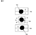
上記BD用光検出器118は図7に示すように、光検出面として中央部にメイン検出面701、上下にサブ検出面702、703が形成されており、A〜D、E〜Hの計8分割の検出面を有する。上記A〜DにはBD用回折格子104で分岐された0次光の情報記録媒体114からの戻り光が検出レンズ117で集光されたメイン光703が入射し、E、FにはBD用回折格子104で分岐された1次光、G、Hには−1次光の情報記録媒体114からの戻り光が検出レンズ117で集光されたサブ光704、705が入射する。フォーカス誤差の検出には非点収差法を用いており、誤差信号はA+C−(B+D)の演算で得られ、RF信号はA+B+C+Dの演算によって得られる。
As shown in FIG. 7, the
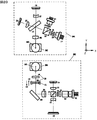
図8はビームエキスパンダー素子110の周辺部分の構成例を示している。凸レンズ109は(図示しない)フレームに固定され、凹レンズ108はホルダ801に取付けられ、左右に設けられたガイドシャフト802により支持されている。ホルダ901はステッピングモータ803のリードスクリュ−804と接続され、このリードスクリュ−804の回転運動により光軸方向132または133の方向に平行移動するようになっている。また、上記(図示しない)フレームにはホルダ801に対向して、凹レンズ108を含むホルダ801の光軸方向の位置を検出するための位置検出センサ805が設けられている。806はホルダ801に設けられた反射面である。この位置検出センサ805は反射面806との距離に応じて出力電圧が直線的に変化する特性をもつように設計されている。図8では位置検出センサ805を非接触の反射タイプとしているが、その他に非接触の透過タイプ、あるいはポテンショメータを利用した接触タイプ等を用いても良い。
FIG. 8 shows a configuration example of the peripheral portion of the
本実施例では光ピックアップの組立時に例えば図9に示すステップ901〜908により調整を行うようにする。まず、基板厚さがL0層と同一の0.1mmに正確に製作された第1の基準ディスクを用い、干渉計やスポット観測装置等を用いて対物レンズ113による集光スポットが最良状態となるようにステッピングモータ803を駆動させ、凹レンズ108の初期位置を調整する。あるいは、フォーカスサーボをかけられる状態にしておき、RF信号の振幅が最大となるようにまたはジッタ値、エラーレート値が最良となるようにステッピングモータ803を駆動させ、凹レンズ108の初期位置を調整する。この状態で、位置検出センサ805の回路807から第1の所定電圧V1が出力されるように上記回路807側で電気的に調整を行う(例えば前記所定電圧V1を前記回路807に記録する等)。次に、基板厚さがL1層と同一の0.075mmに正確に製作された第2の基準ディスクを用い、対物レンズ113による集光スポットが最良状態となるように、あるいはジッタ値、エラーレート値が最良となるように凹レンズ108の位置を調整する。その後、上記回路807から第2の所定電圧V2が出力されるように回路807側で電気的に調整を行う(例えば前記所定電圧V2を前記回路807に記録する等)。
In this embodiment, adjustment is performed by, for example, steps 901 to 908 shown in FIG. 9 when the optical pickup is assembled. First, using a first reference disk accurately manufactured to have a substrate thickness of 0.1 mm which is the same as that of the L0 layer, a focused spot by the
このように調整された光ピックアップのドライブでの動作は例えば、図10に示すステップ1001〜1010のようになり、上記図8と合わせて以下、説明する。ドライブの電源をONの状態にすると、ドライブコントローラ809から位置検出センサ805の回路807、ステッピングモータ803のドライバ回路808を参照しに行く。回路807からの出力電圧を観測しながらステッピングモータ803を駆動させ、上記電圧V1が出力されたら停止させる。この状態で青紫色レーザ101を点灯させ、L0層にフォーカス引込みを行う。ここで、凹レンズ108の光軸方向初期位置が最適位置にある時は、図11(a)に示すように良好なS字曲線1101が得られるが、凹レンズ108の光軸方向初期位置が最適位置からずれている時は、ディスク上の集光スポットに球面収差が発生し絞れなくなる。その結果、フォーカス誤差信号は同図(b)に示すS字曲線1102あるいは1103のように劣化(振幅が低下、オフセットが発生)し、フォーカス引込みに失敗する危険性が出てくる。これを避けるため、L0層にフォーカス引込みを行う以前に(上記で説明したように)位置検出センサ805の回路807から第1の所定電圧V1が出力されるよう凹レンズ108の初期位置を強制的に決める。このようにすれば、同図(a)に示すように良好なS字曲線が得られ、安定にフォーカス引込み動作を開始することが可能になる。さらに実際には、L0層の基板厚さはディスクの半径方向位置によってばらつきを持っているので、凹レンズ108の最適位置が変動する可能性がある。例えば、フォーカス制御を行いながら、BD用光検出器118で得られるRF信号の振幅が最大となるように、あるいはジッタやエラーレート値が最も良くなるように凹レンズ108の位置を微調整する。この微調整は例えば、光ピックアップのディスク半径方向位置が変わった時に適時実施する。ここまでのドライブ動作で凹レンズ108の最適位置に関する情報が獲得されたので、動作履歴とともにドライブコントローラ808に記憶させておく。ディスクをドライブからイジェクトし、ドライブ電源をOFFした状態から再び電源をONさせたとき、あるいはディスクをドライブに挿入したままドライブ電源をOFFした状態から再び電源をONさせたとき、上記の獲得情報は直ちにドライブコントローラ809から回路807およびドライバ回路808に伝達される。このようなシステムにすることにより、より短時間で安定したドライブ動作が可能となり使い勝手が向上するという効果が得られる。
The operation of the optical pickup thus adjusted is as follows, for example, in
ここで、2層媒体において、L0層を記録再生している状態から引き続きL1層へ焦点移動する場合について説明する。このとき凹レンズ108はL0層の基板厚さ0.1mmで最適な位置にある。このままの状態でL1層への焦点移動をしようとしてもL0層との基板厚さの差0.025mmのためディスク上の集光スポットがぼけてしまう。この状態では、L1層に焦点が合っている場合に得られる図12(a)のS字曲線1201に対し、図12(b)に示すS字曲線1202のようになりフォーカス引込みができずL1層への焦点移動に失敗する危険性がある。そこで、例えば図13のステップ1301〜1306に示すように動作させる。ドライブコントローラ809からL1層への焦点移動命令が光ピックアップに送られたら、L1層にフォーカス引込みを行う前に(上記で説明したように)位置検出センサ805の検出回路807から第2の所定電圧V2が出力されるように凹レンズ108の位置を強制的に移動させる。この状態に持って行けばL1層において良好な集光スポットが得られ、図12(a)に示すS字曲線1201となり安定にフォーカス引込み動作を開始することが可能となる。さらに実際には、L1層の基板厚さについてもディスクの半径方向位置によってばらつきを持っているので、凹レンズ108の最適位置が変動する可能性がある。例えば、先ほどL0層における動作で説明した方法と同様に凹レンズ108の位置を微調整する。ここまでのドライブ動作で獲得したL1層での凹レンズ108の位置に関する情報を動作履歴とともにドライブコントローラ809に記憶させておく。再びL1層へ焦点移動させる場合に、上記獲得情報は直ちにドライブコントローラ809から光ピックアップに伝達される。このようにして安定にL1層への焦点移動を行うことが可能となる。また、これまでのドライブ動作でL0層とL1層における凹レンズ108の最適位置情報が獲得されているので、これらの情報を参照することによりL0層→L1層→L0層といった連続的な焦点移動でも安定した動作を行うことが可能となる。本実施例では凸レンズ109を固定し凹レンズ108を可動としたが、逆に凹レンズ108を固定し、凸レンズ109を可動させるようにしても良い。
Here, a case where the focal point is continuously moved from the recording / reproducing state of the L0 layer to the L1 layer in the two-layer medium will be described. At this time, the
これまでBD媒体の場合について説明してきたが、以下、DVD媒体とCD媒体の場合について説明する。図1で示したように、ビームエキスパンダ素子110は波長660nm帯の赤色レーザ119、波長780nm帯の赤外レーザ129と対物レンズ113の間で共通な光路に配置されている。そのためDVD媒体、CD媒体を記録再生する場合には、凹レンズ108の位置を上記BD媒体の場合とは異なる位置に設定する。DVD媒体の場合、図2(B)を用いて説明したように対物レンズ113が設計されているので、コリメートレンズ124から出射した赤色平行光が凹レンズ108に入射し、かつ凸レンズ109から平行光が出射するように凹レンズ108の初期位置が設定される。例えば、波長660nmにおいて上記表1に示したエキスパンダ素子を用いて試算すると、凹レンズ108は凸レンズ109から光軸方向に2.08mm離れた位置に設定すれば良いことになる。
一方、CD媒体の場合には、図2(C)を用いて説明したように対物レンズ113が設計されているので、コリメートレンズ124から出射した赤外平行光が凹レンズ108に入射するが、凸レンズ109からは設計された所定の発散光211が出射するように凹レンズ108の初期位置が設定される。例えば、波長780nmにおいて対物レンズ113の主平面から90mm離れた位置に仮想発光点が来るように設計された対物レンズを想定する。この対物レンズと上記表1で示したエキスパンダ素子を用いて試算すると、凹レンズ108は凸レンズ109から光軸方向に0.32mm離れた位置に設定すれば良いことになる。
Although the case of the BD medium has been described so far, the case of the DVD medium and the CD medium will be described below. As shown in FIG. 1, the
On the other hand, in the case of a CD medium, since the
光ピックアップの組立時に例えば図14に示すステップ1401〜1408により調整を行うようにする。まず、DVDの場合には基板厚さがDVD媒体と同一の0.6mmに作られたDVD基準ディスクを用い、干渉計やスポット観測装置等を用いて対物レンズ113による集光スポットが最良状態となるように凹レンズ108の初期位置を調整する。あるいは、フォーカスサーボをかけられる状態にしておき、ジッタ値、エラーレート値が最良となるように凹レンズ108の初期位置を調整する。この状態で、位置検出センサ805の検出回路807から第3の所定電圧V3が出力されるよう回路807側で電気的に調整を行う。次に、基板厚さがCD媒体と同一の1.2mmに正確に製作されたCD基準ディスクを用い、対物レンズ113による集光スポットが最良状態となるように、またはジッタ値、エラーレート値が最も良くなるように凹レンズ108の初期位置を調整する。この状態で、位置検出センサ805の回路807から第4の所定電圧V4が出力されるように回路807側で電気的に調整を行う。
At the time of assembling the optical pickup, for example, adjustment is performed by steps 1401 to 1408 shown in FIG. First, in the case of a DVD, a DVD reference disk having a substrate thickness of 0.6 mm, which is the same as that of a DVD medium, is used. Thus, the initial position of the
このように調整された光ピックアップのドライブでの動作は例えば図15に示すステップ1501〜1506のようになり、図8と合わせて以下、説明する。ドライブにディスクがローディングされこのディスクがDVD媒体(CD媒体)と判別されると、ドライブコントローラ809から位置検出センサ805の回路807、ステッピングモータ803のドライバ回路808を参照しに行く。回路807から上記の所定電圧V3(V4)が出力されるようにステッピングモータ803を駆動させ、凹レンズ108の位置を決める。この状態でフォーカス引込みを行う。動作中にフォーカス動作が不安定となった場合には、凹レンズ108の光軸方向位置を微調整する。ここまでのドライブ動作により凹レンズ108の位置に関する情報が獲得され、動作履歴とともにドライブコントローラ809に記憶される。ディスクをドライブからイジェクトし、再びDVD媒体(CD媒体)を使用する場合、上記獲得情報は直ちに(図示しない)ドライブコントローラから光ピックアップに伝達される。このようなシステムとすることにより短時間で安定したドライブ動作が可能となり、使い勝手が向上するという効果が得られる。
The operation of the optical pickup adjusted as described above is, for example, steps 1501 to 1506 shown in FIG. 15, and will be described below in conjunction with FIG. When a disc is loaded into the drive and this disc is discriminated as a DVD medium (CD medium), the
本発明では、ディスクをローディングする以前の状態において、ディスク上の集光スポットが基板厚さ0.1mmで最良となるよう球面収差補正用光学素子の状態が予め設定される。この基板厚さ0.1mmはBD1層媒体および2層媒体の第1層目における基板厚さ基準値でかつ使用頻度が最も高いと予想される条件である。その結果、この予め設定した状態を球面収差補正の出発点に設定することができ、ディスクをローディングした後の球面収差補正制御を最も効率良く行うことが可能となる。 In the present invention, the state of the optical element for correcting spherical aberration is set in advance so that the focused spot on the disk becomes the best at a substrate thickness of 0.1 mm before the disk is loaded. The substrate thickness of 0.1 mm is a substrate thickness reference value in the first layer of the BD1 layer medium and the two-layer medium, and is a condition expected to be used most frequently. As a result, this preset state can be set as the starting point for spherical aberration correction, and the spherical aberration correction control after loading the disk can be most efficiently performed.
本発明の実施例2として、BD用対物レンズとDVD/CD互換対物レンズの2個の対物レンズを搭載し、BD、DVD、CDの各媒体に対応可能な光ピックアップについて説明する。図16は本実施例の第1の例を示している。この例では、BD用対物レンズ1601とDVD、CD互換対物レンズ1603が回動型の軸摺動アクチュエータ1602に搭載されており、情報記録媒体114の種類に応じて矢印1604のように使用する対物レンズを切り替える。また、上記DVD、CD互換対物レンズ1603は平行光入射時に情報記録媒体114の記録面での集光スポットの状態が最良となるように設計されている。例えば、波長780nmにおいて上記表1に示したエキスパンダ素子を用いて試算すると、凹レンズ108は凸レンズ109から光軸方向に2.1mm離れた位置に設定すれば良いことになる。上記BD用対物レンズ1601あるいはDVD、CD互換対物レンズ1603までに至る光学系は実施例1の図1と共通であり、既に実施例1で説明済みのためここでは説明を省略する。
As an
図18は本実施例の第2の例を示している。同図のX軸、Y軸、Z軸はそれぞれ情報記録媒体の接線方向、半径方向、面振れ方向を示しており、上段はXY平面図を下段はXZ平面図を示している。この例では、BD用対物レンズ1601とDVD、CD互換対物レンズ1603はX軸に平行に並んでレンズホルダ1801に搭載されており、駆動コイル1802を含む(図示しない)アクチュエータによって同図のY軸、Z軸方向への並進微小駆動およびX軸回り、Y軸回りの回転微小駆動が可能となっている。
FIG. 18 shows a second example of this embodiment. The X axis, Y axis, and Z axis of the figure show the tangential direction, radial direction, and surface deflection direction of the information recording medium, respectively, with the upper part showing the XY plan view and the lower part showing the XZ plan view. In this example, the
青紫色レーザ101から出射された発散光は、偏光ビームスプリッタ105を透過しBD用コリメートレンズ106で平行光となり、折返しミラー1804で反射され、ビームエキスパンダ素子110を透過し、立上げミラー1803で反射される。その後、1/4波長板112を透過し、BD用対物レンズ1601により集光され、情報記録媒体114(この場合、記録層が1層あるいは2層以上のBD媒体)の情報記録面に到達する。なお、青紫色レーザ101から出射された発散光の一部は偏光ビームスプリッタ105で反射され、レンズ115で集光されてBD用前方モニタ116に到達し、青紫色レーザ101の発光量がモニタされる。情報記録媒体114からの反射戻り光は、BD用対物レンズ1601、1/4波長板112を透過し、立上げミラー1803で反射され、ビームエキスパンダ素子110を透過し、折返しミラー1804で反射される。その後、コリメートレンズ106を透過、偏光ビームスプリッタ105で反射され、検出レンズ117により集光されてBD用光検出器118の検出面に到達する。
The divergent light emitted from the blue-
赤色レーザ119から出射された発散光は、合成プリズム122を透過後、ハーフミラー123で反射され、コリメートレンズ1805から平行光が出射される。その後、立上げミラー1803で反射され、DVD、CD互換対物レンズ1603により集光され、情報記録媒体114の情報記録面(この場合、記録層が1層あるいは2層のDVD媒体)に到達する。情報記録媒体114からの反射戻り光は、DVD、CD互換対物レンズ1603を透過し、立上げミラー1803で反射され、コリメートレンズ1805、ハーフミラー123を透過する。検出レンズ127により集光されDVD/CD用光検出器128の光検出面に到達する。
The divergent light emitted from the
波長780nm帯の赤外レーザ129から出射された発散光は合成プリズム122、ハーフミラー123で反射され、コリメートレンズ1805から平行光が出射される。その後、立上げミラー1803で反射し、DVD、CD互換対物レンズ1603により集光され、情報記録媒体114(この場合、CD媒体)の情報記録面に到達する。情報記録媒体114からの反射戻り光がDVD/CD用光検出器128の光検出面まで到達する光路は上記赤色レーザ119のDVD光学系と同じであり、ここでは説明を省略する。
The divergent light emitted from the
図19は本実施例の第3の例を示している。同図のX軸、Y軸、Z軸はそれぞれ情報記録媒体の接線方向、半径方向、面振れ方向を示しており、上段はXY平面図を下段はYZ平面図を示している。この例では、BD用対物レンズ1601とDVD、CD互換対物レンズ1603はY軸に平行に並んでレンズホルダ1901に搭載されており、駆動コイル1904を含む(図示しない)アクチュエータによって同図のY軸、Z軸方向への並進微小駆動およびX軸回り、Y軸回りの回転微小駆動が可能となっている。BD用立上げミラー1902は図の−X方向から入射したBD光を反射してBD用対物レンズ1601に入射させ、DVD/CD用立上げミラー1903は図のY方向から入射したDVD/CD光を反射してDVD、CD互換対物レンズ1603に入射させる。これ以外の光路については上記第2の例と同じであるため、ここでは説明を省略する。
FIG. 19 shows a third example of this embodiment. The X axis, Y axis, and Z axis in the figure indicate the tangential direction, the radial direction, and the surface deflection direction of the information recording medium, respectively. In this example, the
図20は本実施例の第4の例を示している。同図のX軸、Y軸、Z軸はそれぞれ情報記録媒体の接線方向、半径方向、面振れ方向を示しており、上段の点線部2001はDVD/CD光学系を搭載したDVD/CD用光ピックアップを、下段の点線部2002はBD光学系を搭載したBD用光ピックアップを示している。これらは別々の(図示しない)ピックアップケースに収められている。
FIG. 20 shows a fourth example of this embodiment. The X axis, Y axis, and Z axis in the figure indicate the tangential direction, the radial direction, and the surface deflection direction of the information recording medium, respectively, and the upper dotted
なお、図16、図18、図19、図20では赤色レーザ119と赤外レーザ129が別個に設けられているが、光学系簡素化のためこれらのレーザを一体化した2波長レーザを用いることも可能である。また、ドライブの仕様によっては例えば、赤外レーザ129が無く、青紫色レーザ101と赤色レーザ119を搭載した光学系としても良い。
In FIG. 16, FIG. 18, FIG. 19, and FIG. 20, the
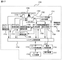
上記実施例1、2では光ピックアップの実施例を説明してきたが、ここでは上記光ピックアップを搭載した光学的記録再生装置の実施例を説明する。図17は情報の再生または記録再生を行う情報記録再生装置1701の概略ブロック図を示している。1702は上記実施例1、実施例2で説明した光ピックアップを示しており、この光ピックアップ1702から検出された信号は信号処理回路内のサーボ信号生成回路1703および情報信号再生回路1704に送られる。サーボ信号生成回路1703では、光ピックアップ1402より検出された信号から光ディスク媒体1705に適したフォーカス制御信号、トラッキング制御信号、球面収差検出信号が生成され、これらをもとにACT駆動回路1706を経て光ピックアップ1702内の(図示しない)ACTを駆動し、対物レンズ1707の位置制御を行う。また、上記サーボ信号生成回路1703では上記光ピックアップ1702より球面収差検出信号が生成され、この信号をもとに球面収差補正駆動回路1708を経て光ピックアップ1702内の(図示しない)ビームエキスパンダ素子の補正レンズを駆動する。また、情報信号再生回路1704では光ピックアップ1702から検出された信号から光ディスク1705に記録された情報信号が再生され、その情報信号は情報信号出力端子1709へ出力される。なお、サーボ信号生成回路1703および、情報信号再生回路1704で得られた信号の一部はシステム制御回路1710に送られる。システム制御回路1710からはレーザ駆動用記録信号が送られ、レーザ光源点灯回路1711を駆動させて発光量の制御を行い、光ピックアップ1702を介して、光ディスク1705に記録信号を記録する。なお、このシステム制御回路1710にはアクセス制御回路1712とスピンドルモータ駆動回路1713が接続されており、それぞれ、光ピックアップ1702の半径方向位置制御や光ディスク1705のスピンドルモータ1714の回転制御が行われる。なお、パーソナルコンピュータあるいはAV用レコーダ等によりユーザが制御する場合には、キーボード、タッチパネル、ジョグダイアル等のユーザ入力装置1718からユーザがユーザ入力処理回路1715に指示を与え、上記情報記録再生装置1701の制御を行う。その際、情報記録再生装置1701の処理状態等は表示処理回路1716によって行われ、液晶パネル、CRT等の表示装置1717に表示される。
Although the embodiments of the optical pickup have been described in the first and second embodiments, an embodiment of an optical recording / reproducing apparatus equipped with the optical pickup will be described here. FIG. 17 shows a schematic block diagram of an information recording / reproducing
101・・・青紫色レーザ、113・・・対物レンズ、108・・・凹レンズ
109・・・凸レンズ、110・・・ビームエキスパンダ素子
114・・・情報記録媒体、118・・・BD用光検出器、119・・・赤色レーザ
129・・・赤外レーザ、805・・・位置検出センサ
809・・・ドライブコントローラ、807・・・位置検出センサ805の回路
808・・・ステッピングモータ803のドライバ回路
DESCRIPTION OF
Claims (13)
記録面で集光スポットが最良となる状態に上記球面収差補正用光学素子が設定されていることを特徴とする光ピックアップ。 An optical pickup comprising a laser light source, a spherical aberration correcting optical element, a photodetector, an objective lens, and irradiating an information recording medium with a light spot for recording and reproducing information,
An optical pickup characterized in that the spherical aberration correcting optical element is set in a state where the condensing spot is optimal on the recording surface.
異なる波長の光を出射する2つ以上のレーザ光源と、
前記レーザ光源から出射された光を共通にする光学素子と、
前記レーザ光源から出射された光の共通光路に配置された球面収差補正用光学素子と、
前記レーザ光源から出射された光をいずれも集光可能な対物レンズを備え、
前記情報記録媒体がローディングされる前に、前記異なる波長の光の内、所定の光を用いて記録再生を行う情報記録媒体の所定の層の記録面で集光スポットが最良となる状態に前記球面収差補正用光学素子が設定されていることを特徴とする光ピックアップ。 An optical pickup comprising a laser light source, a spherical aberration correcting optical element, a photodetector, an objective lens, and irradiating an information recording medium with a light spot for recording and reproducing information,
Two or more laser light sources that emit light of different wavelengths;
An optical element for sharing light emitted from the laser light source;
A spherical aberration correcting optical element disposed in a common optical path of light emitted from the laser light source;
An objective lens capable of condensing all the light emitted from the laser light source;
Before the information recording medium is loaded, the condensing spot is best in the recording surface of the predetermined layer of the information recording medium that performs recording / reproduction using the predetermined light among the light of the different wavelengths. An optical pickup comprising a spherical aberration correcting optical element.
前記情報記録媒体は多層媒体であり、
前記所定の層は第1層目であり、基板厚さが0.1mmであることを特徴とする光ピックアップ。 The optical pickup according to claim 2, wherein
The information recording medium is a multilayer medium,
The optical pickup according to claim 1, wherein the predetermined layer is a first layer and a substrate thickness is 0.1 mm.
前記対物レンズは、平行光が入射された場合、2層ディスク媒体の1層目と2層目の中間位置で集光スポットが最良となるように設定され、
前記情報記録媒体がローディングされる前に、前記対物レンズに所定の発散光が入射されるように前記球面収差補正用光学素子が設定されていることを特徴とする光ピックアップ。 The optical pickup according to claim 2, wherein
The objective lens is set so that the condensing spot is best at the intermediate position between the first layer and the second layer of the two-layer disc medium when parallel light is incident thereon,
2. The optical pickup according to claim 1, wherein the spherical aberration correcting optical element is set so that predetermined divergent light is incident on the objective lens before the information recording medium is loaded.
波長λ1、波長λ2又は波長λ3の光を出射する2つ以上のレーザ光源と、
前記レーザ光源から出射された光を共通にする光学素子と、
前記レーザ光源から出射された光の共通光路に配置された球面収差補正用光学素子と、
前記レーザ光源から出射された光をいずれも集光可能な対物レンズを備え、
前記対物レンズは、波長λ1の平行光が入射された場合、前記波長λ1の光を用いて記録再生を行なう第1の情報記録媒体である2層ディスク媒体の1層目と2層目の中間位置で集光スポットが最良となるように設定され、
前記対物レンズは、波長λ2の平行光が入射された場合、前記波長λ2の光を用いて記録再生を行う第2の情報記録媒体の記録面で集光スポットが最良となるように設定され、
前記対物レンズは、波長λ3の発散光が入射された場合、上記波長λ3の光を用いて記録再生を行う第3の情報記録媒体の記録面で集光スポットが最良となるように設定され、
前記情報記録媒体がローディングされる前に、前記対物レンズに前記波長λ1で発散光が入射されるように前記球面収差補正用光学素子が設定されていることを特徴とする光ピックアップ。 An optical pickup comprising a laser light source, a spherical aberration correcting optical element, a photodetector, an objective lens, and irradiating an information recording medium with a light spot for recording and reproducing information,
Two or more laser light sources that emit light of wavelength λ1, wavelength λ2, or wavelength λ3;
An optical element for sharing light emitted from the laser light source;
A spherical aberration correcting optical element disposed in a common optical path of light emitted from the laser light source;
An objective lens capable of condensing all the light emitted from the laser light source;
When the parallel light of wavelength λ1 is incident, the objective lens is intermediate between the first layer and the second layer of a two-layer disc medium that is a first information recording medium that performs recording and reproduction using the light of wavelength λ1. The focal spot is set at the best position,
The objective lens is set so that the condensing spot is the best on the recording surface of the second information recording medium that performs recording and reproduction using the light of wavelength λ2, when parallel light of wavelength λ2 is incident,
The objective lens is set so that when the divergent light having the wavelength λ3 is incident, the focused spot is the best on the recording surface of the third information recording medium that performs recording and reproduction using the light having the wavelength λ3.
2. The optical pickup according to claim 1, wherein the spherical aberration correcting optical element is set so that divergent light is incident on the objective lens at the wavelength λ1 before the information recording medium is loaded.
前記情報記録媒体が情報記録媒体の記録面で集光スポットが最良となる球面収差補正用光学素子の状態が電気的手段により調整されていることを特徴とする光ピックアップ。 The optical pickup according to claim 2, wherein
An optical pickup characterized in that the state of the spherical aberration correcting optical element in which the information recording medium is the best recording spot on the recording surface of the information recording medium is adjusted by electric means.
前記情報記録媒体が多層ディスク媒体である場合に、
前記情報記録媒体における2層媒体の1層目から2層目に集光スポットの焦点を移動させる場合に、又は2層目から1層目に集光スポットの焦点を移動させる場合に、2層目又は1層目にフォーカス引込み動作を行う以前に球面収差補正用光学素子の状態が上記2層目又は1層目の記録面で最良となる状態に設定変更されることを特徴とする光ピックアップ。 The optical pickup according to claim 2, wherein
When the information recording medium is a multilayer disk medium,
Two layers when the focal point of the condensed spot is moved from the first layer to the second layer of the two-layer medium in the information recording medium, or when the focal point of the condensed spot is moved from the second layer to the first layer An optical pickup characterized in that the state of the optical element for correcting spherical aberration is changed to the best state on the recording surface of the second layer or the first layer before performing the focus pull-in operation on the first layer or the first layer. .
前記情報記録媒体がローディングされた後に、前記対物レンズに所定の発散光または収束光が入射されるように前記球面収差補正用光学素子の状態が設定されることを特徴とする光ピックアップ。 The optical pickup according to claim 1,
An optical pickup characterized in that after the information recording medium is loaded, the state of the spherical aberration correcting optical element is set so that predetermined divergent light or convergent light is incident on the objective lens.
前記情報記録媒体がローディングされた後に、前記対物レンズに波長λ1の所定の発散光または収束光が入射されるように前記球面収差補正用光学素子の状態が設定されることを特徴とする光ピックアップ。 The optical pickup according to claim 2, wherein
An optical pickup characterized in that after the information recording medium is loaded, the state of the optical element for correcting spherical aberration is set so that predetermined divergent light or convergent light having a wavelength λ1 is incident on the objective lens. .
前記情報記録媒体がローディングされた後に、その媒体が前記第2又は第3の情報記録媒体の情報記録媒体と判別された場合、前記球面収差補正用光学素子の状態が前記第2又は第3の情報記録媒体の記録面で集光スポットが最良となるように設定されることを特徴とする光ピックアップ。 The optical pickup according to claim 5, wherein
After the information recording medium is loaded, when the medium is determined as the information recording medium of the second or third information recording medium, the state of the spherical aberration correcting optical element is the second or third information recording medium. An optical pickup characterized by being set so that a condensing spot is best on a recording surface of an information recording medium.
前記情報記録媒体のイジェクト命令が下され実際に前記情報記録媒体がイジェクトされるまでの間、又は前記ドライブの電源が切断されるまでの間に、前記ドライブの動作中に獲得した前記球面収差補正用光学素子の最適状態情報が前記ドライブのメイン制御回路に記憶されることを特徴とする光学的情報再生装置。 A drive equipped with the optical pickup according to claim 1 or 2,
The spherical aberration correction acquired during operation of the drive until the information recording medium is ejected and the information recording medium is actually ejected, or until the power of the drive is turned off. An optical information reproducing apparatus characterized in that optimum state information of the optical element is stored in a main control circuit of the drive.
前記ドライブの電源が入ると同時に前記メイン制御回路を参照し、前記情報記録媒体がローディングされるまでの間に、前回のドライブ動作で獲得された前記球面収差補正用光学素子の最適状態情報が前記光ピックアップにフィードバックされることを特徴とする光学的情報再生装置。 The optical information reproducing apparatus according to claim 11, wherein
The optimum state information of the spherical aberration correcting optical element obtained in the previous drive operation is referred to by referring to the main control circuit at the same time when the drive is turned on and before the information recording medium is loaded. An optical information reproducing apparatus fed back to an optical pickup.
前記第1の基準ディスクに対する集光スポットの収差値が最小を示すように凹レンズの初期位置を調整するステップと、
前記初期位置を調整する第1の所定の電圧が出力されるように調整するステップと、
前記第2の基準ディスクに対する集光スポットが最良状態になるように凹レンズの初期位置を調整するステップと、
前記初期位置を調整する第2の所定の電圧が出力されるように調整するステップと、
を備え、
前記光ピックアップが動作するときには、前記凹レンズの初期位置を前記第1の所定の電圧又は前記第2の所定の電圧が出力されることで前記光ピックアップが調整されることを特徴とする光ピックアップ調整方法。
An optical pickup adjusting method using a first reference disk having a substrate thickness of 0.1 mm and a second reference disk having a substrate thickness of 0.075 mm,
Adjusting the initial position of the concave lens so that the aberration value of the focused spot with respect to the first reference disk is minimal;
Adjusting to output a first predetermined voltage for adjusting the initial position;
Adjusting the initial position of the concave lens so that the focused spot with respect to the second reference disk is in the best condition;
Adjusting to output a second predetermined voltage for adjusting the initial position;
With
When the optical pickup operates, the optical pickup is adjusted by outputting the first predetermined voltage or the second predetermined voltage as an initial position of the concave lens. Method.
Priority Applications (7)
| Application Number | Priority Date | Filing Date | Title |
|---|---|---|---|
| JP2005052245A JP2006236513A (en) | 2005-02-28 | 2005-02-28 | Optical pickup |
| US11/302,540 US20060193217A1 (en) | 2005-02-28 | 2005-12-14 | Optical pickup and optical information reproducing device |
| CN2006100004417A CN1828744B (en) | 2005-02-28 | 2006-01-05 | Optical pickup and optical information reproducing device |
| CN2008100958496A CN101266810B (en) | 2005-02-28 | 2006-01-05 | Optical pick-up device and optical information reproduction device |
| CN2008100958481A CN101364412B (en) | 2005-02-28 | 2006-01-05 | Optical pick-up device and optical information reproduction device |
| US12/693,042 US20100124161A1 (en) | 2005-02-28 | 2010-01-25 | Optical pickup and optical information reproducing device |
| US12/693,000 US20100124153A1 (en) | 2005-02-28 | 2010-01-25 | Optical pickup and optical information reproducing device |
Applications Claiming Priority (1)
| Application Number | Priority Date | Filing Date | Title |
|---|---|---|---|
| JP2005052245A JP2006236513A (en) | 2005-02-28 | 2005-02-28 | Optical pickup |
Related Child Applications (1)
| Application Number | Title | Priority Date | Filing Date |
|---|---|---|---|
| JP2010035552A Division JP2010118144A (en) | 2010-02-22 | 2010-02-22 | Optical pickup and optical information reproducing device |
Publications (2)
| Publication Number | Publication Date |
|---|---|
| JP2006236513A true JP2006236513A (en) | 2006-09-07 |
| JP2006236513A5 JP2006236513A5 (en) | 2008-03-27 |
Family
ID=36931825
Family Applications (1)
| Application Number | Title | Priority Date | Filing Date |
|---|---|---|---|
| JP2005052245A Pending JP2006236513A (en) | 2005-02-28 | 2005-02-28 | Optical pickup |
Country Status (3)
| Country | Link |
|---|---|
| US (3) | US20060193217A1 (en) |
| JP (1) | JP2006236513A (en) |
| CN (3) | CN101266810B (en) |
Cited By (7)
| Publication number | Priority date | Publication date | Assignee | Title |
|---|---|---|---|---|
| JP2009116937A (en) * | 2007-11-05 | 2009-05-28 | Pioneer Electronic Corp | Pickup device or the like |
| JP2009123315A (en) * | 2007-11-19 | 2009-06-04 | Fujinon Corp | Objective lens, optical pickup device with the same, and optical recording medium recording and/or playback device mounting this optical pickup device |
| JP2009123316A (en) * | 2007-11-19 | 2009-06-04 | Fujinon Corp | Objective lens, optical pickup device provided with the same, and optical recording medium recording and/or playback device mounting this optical pickup device |
| JP2009123317A (en) * | 2007-11-19 | 2009-06-04 | Fujinon Corp | Objective lens, optical pickup device provided with the same, and optical recording medium recording and/or playback device mounting this optical pickup device |
| JP2009301671A (en) * | 2008-06-16 | 2009-12-24 | Sanyo Electric Co Ltd | Optical pickup device |
| US7903529B2 (en) | 2006-10-05 | 2011-03-08 | Panasonic Corporation | Optical head and optical disc device |
| US8289828B2 (en) | 2010-07-29 | 2012-10-16 | Hitachi Media Electronics Co., Ltd. | Optical data recording/reproduction apparatus |
Families Citing this family (3)
| Publication number | Priority date | Publication date | Assignee | Title |
|---|---|---|---|---|
| JP4969142B2 (en) * | 2006-04-27 | 2012-07-04 | 株式会社日立製作所 | Optical disc apparatus and driving method thereof |
| US7933182B2 (en) * | 2006-12-13 | 2011-04-26 | Canon Kabushiki Kaisha | Optical information recording and reproducing apparatus that sets a movable range of an objective lens based on the type of recording medium |
| CN101221780B (en) * | 2007-01-11 | 2010-05-19 | 财团法人工业技术研究院 | Multi-wavelength optical read-write head device |
Citations (4)
| Publication number | Priority date | Publication date | Assignee | Title |
|---|---|---|---|---|
| JP2003016660A (en) * | 2001-06-29 | 2003-01-17 | Sony Corp | Optical pickup and recording/reproducing device |
| JP2003077142A (en) * | 2001-06-22 | 2003-03-14 | Pioneer Electronic Corp | Device and method for controlling focusing of optical pickup |
| JP2003323735A (en) * | 2002-02-27 | 2003-11-14 | Ricoh Co Ltd | Optical pickup, and optical information processing apparatus using the same |
| JP2004319062A (en) * | 2003-03-31 | 2004-11-11 | Konica Minolta Holdings Inc | Optical pickup device |
Family Cites Families (7)
| Publication number | Priority date | Publication date | Assignee | Title |
|---|---|---|---|---|
| US5447190A (en) * | 1993-02-04 | 1995-09-05 | Nokia-Maillefer Sa | Device and method for cooling an extrusion cylinder |
| US5757758A (en) * | 1995-12-19 | 1998-05-26 | Konica Corporation | Optical pickup apparatus objective lens and converging optical system for optical pickup and optical disk apparatus |
| KR100234261B1 (en) * | 1996-06-07 | 1999-12-15 | 윤종용 | Compatible optical pickup device |
| EP1968053A3 (en) * | 2000-05-12 | 2012-03-07 | Konica Minolta Opto, Inc. | Optical pick-up apparatus |
| US6934226B2 (en) * | 2001-04-12 | 2005-08-23 | Matsushita Electric Industrial Co., Ltd. | Optical disk apparatus |
| EP1965380B1 (en) * | 2002-02-27 | 2009-12-30 | Ricoh Company, Ltd. | Optical pickup and optical information processing apparatus |
| US7245407B2 (en) * | 2002-06-10 | 2007-07-17 | Matsushita Electric Industrial Co., Ltd. | Complex objective lens compatible with information media of different thicknesses |
-
2005
- 2005-02-28 JP JP2005052245A patent/JP2006236513A/en active Pending
- 2005-12-14 US US11/302,540 patent/US20060193217A1/en not_active Abandoned
-
2006
- 2006-01-05 CN CN2008100958496A patent/CN101266810B/en not_active Expired - Fee Related
- 2006-01-05 CN CN2008100958481A patent/CN101364412B/en not_active Expired - Fee Related
- 2006-01-05 CN CN2006100004417A patent/CN1828744B/en not_active Expired - Fee Related
-
2010
- 2010-01-25 US US12/693,042 patent/US20100124161A1/en not_active Abandoned
- 2010-01-25 US US12/693,000 patent/US20100124153A1/en not_active Abandoned
Patent Citations (4)
| Publication number | Priority date | Publication date | Assignee | Title |
|---|---|---|---|---|
| JP2003077142A (en) * | 2001-06-22 | 2003-03-14 | Pioneer Electronic Corp | Device and method for controlling focusing of optical pickup |
| JP2003016660A (en) * | 2001-06-29 | 2003-01-17 | Sony Corp | Optical pickup and recording/reproducing device |
| JP2003323735A (en) * | 2002-02-27 | 2003-11-14 | Ricoh Co Ltd | Optical pickup, and optical information processing apparatus using the same |
| JP2004319062A (en) * | 2003-03-31 | 2004-11-11 | Konica Minolta Holdings Inc | Optical pickup device |
Cited By (8)
| Publication number | Priority date | Publication date | Assignee | Title |
|---|---|---|---|---|
| US7903529B2 (en) | 2006-10-05 | 2011-03-08 | Panasonic Corporation | Optical head and optical disc device |
| JP2009116937A (en) * | 2007-11-05 | 2009-05-28 | Pioneer Electronic Corp | Pickup device or the like |
| JP2009123315A (en) * | 2007-11-19 | 2009-06-04 | Fujinon Corp | Objective lens, optical pickup device with the same, and optical recording medium recording and/or playback device mounting this optical pickup device |
| JP2009123316A (en) * | 2007-11-19 | 2009-06-04 | Fujinon Corp | Objective lens, optical pickup device provided with the same, and optical recording medium recording and/or playback device mounting this optical pickup device |
| JP2009123317A (en) * | 2007-11-19 | 2009-06-04 | Fujinon Corp | Objective lens, optical pickup device provided with the same, and optical recording medium recording and/or playback device mounting this optical pickup device |
| US8064319B2 (en) | 2007-11-19 | 2011-11-22 | Fujinon Corporation | Objective lens, optical pickup device having the same, and recording and/or reproducing apparatus for optical recording medium, equipped with the optical pickup device |
| JP2009301671A (en) * | 2008-06-16 | 2009-12-24 | Sanyo Electric Co Ltd | Optical pickup device |
| US8289828B2 (en) | 2010-07-29 | 2012-10-16 | Hitachi Media Electronics Co., Ltd. | Optical data recording/reproduction apparatus |
Also Published As
| Publication number | Publication date |
|---|---|
| CN101266810B (en) | 2011-05-11 |
| CN101364412B (en) | 2012-07-04 |
| US20100124153A1 (en) | 2010-05-20 |
| CN1828744B (en) | 2011-01-12 |
| CN1828744A (en) | 2006-09-06 |
| CN101266810A (en) | 2008-09-17 |
| US20060193217A1 (en) | 2006-08-31 |
| CN101364412A (en) | 2009-02-11 |
| US20100124161A1 (en) | 2010-05-20 |
Similar Documents
| Publication | Publication Date | Title |
|---|---|---|
| JP2006236513A (en) | Optical pickup | |
| US8391120B2 (en) | Optical head, optical disc device and information processing device | |
| JP2004295983A (en) | Optical head, and optical recording/reproducing device using the same | |
| JP5069893B2 (en) | Optical pickup and optical disk drive | |
| JP4538453B2 (en) | Optical information device and method for controlling optical information device | |
| JP5169981B2 (en) | Optical pickup, optical disc apparatus, optical pickup manufacturing method, and optical pickup control method | |
| US20060077809A1 (en) | Optical pickup and disc drive apparatus | |
| JP4663614B2 (en) | Optical pickup and optical information recording / reproducing apparatus | |
| JP2008192188A (en) | Optical disk unit and optical head device | |
| JP2010118144A (en) | Optical pickup and optical information reproducing device | |
| US20070237053A1 (en) | Aberration correcting unit, optical pickup device, information reproducing apparatus, and aberration correcting program | |
| JP2006202375A (en) | Optical head and optical disk reproduction device | |
| JP2010073238A (en) | Optical pickup, objective lens, spherical aberration correcting element, and optical information recording and playback device | |
| JP2010211842A (en) | Optical pickup, optical information reproducing device, and optical information recording and reproducing device | |
| JP2006196053A (en) | Information processor | |
| US20110002117A1 (en) | Optical disc drive | |
| JP5121762B2 (en) | Optical pickup | |
| JP2008293606A (en) | Optical pickup device | |
| JP4332799B2 (en) | Optical pickup, disk drive device, and adjustment value detection method for focus bias and spherical aberration in optical pickup | |
| JP2008112510A (en) | Optical pickup device and optical disk device | |
| JP5397395B2 (en) | Optical disk device | |
| JP4652972B2 (en) | Compatible objective lens unit, its design method and compatible optical pickup | |
| JP2007184028A (en) | Optical head and optical disk device | |
| JP2004164825A (en) | Optical pickup device | |
| JP2012169019A (en) | Optical disk device |
Legal Events
| Date | Code | Title | Description |
|---|---|---|---|
| A521 | Request for written amendment filed |
Free format text: JAPANESE INTERMEDIATE CODE: A523 Effective date: 20060616 |
|
| A521 | Request for written amendment filed |
Free format text: JAPANESE INTERMEDIATE CODE: A523 Effective date: 20080201 |
|
| A621 | Written request for application examination |
Free format text: JAPANESE INTERMEDIATE CODE: A621 Effective date: 20080201 |
|
| A521 | Request for written amendment filed |
Free format text: JAPANESE INTERMEDIATE CODE: A523 Effective date: 20080201 |
|
| A977 | Report on retrieval |
Free format text: JAPANESE INTERMEDIATE CODE: A971007 Effective date: 20091109 |
|
| A131 | Notification of reasons for refusal |
Free format text: JAPANESE INTERMEDIATE CODE: A131 Effective date: 20091222 |
|
| A521 | Request for written amendment filed |
Free format text: JAPANESE INTERMEDIATE CODE: A523 Effective date: 20100222 |
|
| A02 | Decision of refusal |
Free format text: JAPANESE INTERMEDIATE CODE: A02 Effective date: 20100316 |
|
| A521 | Request for written amendment filed |
Free format text: JAPANESE INTERMEDIATE CODE: A523 Effective date: 20100609 |
|
| A521 | Request for written amendment filed |
Free format text: JAPANESE INTERMEDIATE CODE: A523 Effective date: 20100609 |
|
| A911 | Transfer to examiner for re-examination before appeal (zenchi) |
Free format text: JAPANESE INTERMEDIATE CODE: A911 Effective date: 20100701 |
|
| A912 | Re-examination (zenchi) completed and case transferred to appeal board |
Free format text: JAPANESE INTERMEDIATE CODE: A912 Effective date: 20100813 |