WO2012005078A1 - クラッチカバー組立体 - Google Patents
クラッチカバー組立体 Download PDFInfo
- Publication number
- WO2012005078A1 WO2012005078A1 PCT/JP2011/063282 JP2011063282W WO2012005078A1 WO 2012005078 A1 WO2012005078 A1 WO 2012005078A1 JP 2011063282 W JP2011063282 W JP 2011063282W WO 2012005078 A1 WO2012005078 A1 WO 2012005078A1
- Authority
- WO
- WIPO (PCT)
- Prior art keywords
- pressure plate
- meshing
- clutch cover
- movement
- wear
- Prior art date
- Legal status (The legal status is an assumption and is not a legal conclusion. Google has not performed a legal analysis and makes no representation as to the accuracy of the status listed.)
- Ceased
Links
Images




Classifications
-
- F—MECHANICAL ENGINEERING; LIGHTING; HEATING; WEAPONS; BLASTING
- F16—ENGINEERING ELEMENTS AND UNITS; GENERAL MEASURES FOR PRODUCING AND MAINTAINING EFFECTIVE FUNCTIONING OF MACHINES OR INSTALLATIONS; THERMAL INSULATION IN GENERAL
- F16D—COUPLINGS FOR TRANSMITTING ROTATION; CLUTCHES; BRAKES
- F16D13/00—Friction clutches
- F16D13/58—Details
- F16D13/70—Pressure members, e.g. pressure plates, for clutch-plates or lamellae; Guiding arrangements for pressure members
-
- F—MECHANICAL ENGINEERING; LIGHTING; HEATING; WEAPONS; BLASTING
- F16—ENGINEERING ELEMENTS AND UNITS; GENERAL MEASURES FOR PRODUCING AND MAINTAINING EFFECTIVE FUNCTIONING OF MACHINES OR INSTALLATIONS; THERMAL INSULATION IN GENERAL
- F16D—COUPLINGS FOR TRANSMITTING ROTATION; CLUTCHES; BRAKES
- F16D13/00—Friction clutches
- F16D13/58—Details
- F16D13/75—Features relating to adjustment, e.g. slack adjusters
- F16D13/757—Features relating to adjustment, e.g. slack adjusters the adjusting device being located on or inside the clutch cover, e.g. acting on the diaphragm or on the pressure plate
Definitions
- the present invention relates to a clutch cover assembly, and more particularly to a clutch cover assembly for pressing and releasing a friction member of a clutch disk assembly against a flywheel of an engine.
- the clutch cover assembly is generally mounted on an engine flywheel and used to transmit engine driving force to the transmission side.
- a clutch cover assembly mainly includes a clutch cover, a pressure plate, and a diaphragm spring.
- the clutch cover is fixed to the flywheel.
- the pressure plate is pressed to the flywheel side by the diaphragm spring, and the friction member of the clutch disc assembly is sandwiched between the flywheel and the pressure plate.
- the diaphragm spring has a lever function for releasing the pressure on the pressure plate as well as a function of pressing the pressure plate.
- a wear compensation mechanism that suppresses an increase in pressing load by returning the diaphragm spring to its initial state even when the friction member is worn.
- This wear compensation mechanism mainly detects a fulcrum ring disposed between the pressure plate and the diaphragm spring, a urging mechanism that urges the fulcrum ring in a direction away from the pressure plate, and a wear amount of the friction member.
- a wear amount detection mechanism Here, the diaphragm spring presses the pressure plate via the fulcrum ring. Then, the diaphragm spring is maintained in the initial set posture by moving the fulcrum ring to the side away from the pressure plate in accordance with the wear amount of the friction member.
- a wear compensation mechanism shown in Patent Document 2 is also provided.
- a cone spring for absorbing vibration is provided in the wear amount detection mechanism to stabilize the operation for wear compensation.
- a wear amount detection mechanism is constituted by a bush and a bolt that penetrates the bush, and the wear amount is detected by a gap between the two according to wear.
- a clutch cover assembly is for pressing and releasing a friction member of a clutch disk assembly against a flywheel of an engine, and includes a clutch cover fixed to the flywheel, a pressure plate, A pressing member, a wear amount detection mechanism, and a wear tracking mechanism are provided.
- the pressure plate is connected to the clutch cover so as not to rotate relative to the clutch cover, and presses the friction member against the flywheel.
- the pressing member is a member for pressing the pressure plate toward the flywheel while being supported by the clutch cover.
- the wear amount detection mechanism is a mechanism having a plurality of mesh positions, and a movement detection member that releases the mesh at the first mesh position and moves to the second mesh position when the friction member reaches a predetermined wear amount. Have.
- the wear tracking mechanism moves the pressing member to the initial posture side according to the movement amount of the movement detection member.
- the wear amount of the friction member is detected by a wear amount detection mechanism.
- a plurality of meshing positions are set in the wear amount detecting mechanism, and the movement detecting member moves from the first meshing position engaged until then to the second meshing position when the friction member wears a predetermined amount. Therefore, the detected wear amount, that is, the wear amount detection result, is retained unless the meshing is released. For this reason, compared with the conventional mechanism for detecting the amount of wear, the operation is stable and accurate wear compensation can be performed.
- the clutch cover assembly is the clutch cover assembly of the first aspect, wherein the wear amount detection mechanism is further supported by the clutch cover and further includes a cover side detection member having a plurality of first meshing portions. Yes.
- the movement detecting member moves with the pressure plate and has a second meshing portion that can mesh with the plurality of first meshing portions, and the first meshing of the second meshing portion when the friction member reaches a predetermined wear amount. The engagement with the part is released.
- the cover detection member is supported by the clutch cover, and the second engagement portion of the movement detection member is engaged with the first engagement portion formed on the cover detection member. And if a pressure plate moves by abrasion of a friction member, a movement detection member will also move with the movement. When the wear amount reaches a predetermined amount, the engagement between the movement detection member and the cover side detection member is released, and the both detection members are engaged at different engagement positions.
- a clutch cover assembly is the clutch cover assembly of the second aspect, wherein the wear amount detection mechanism urges the movement detection member in the direction in which the plurality of first meshing portions are arranged, and the both meshing portions.
- a first biasing member that moves the movement detecting member to the second meshing position when the meshing at the first meshing position is released.
- the movement detection member is disengaged from the cover side detection member when the friction member is worn by a predetermined amount.
- the movement detecting member is urged in the moving direction by the first urging member, when the engagement is released, the movement detecting member is smoothly moved to the next engagement position by the urging force of the first urging member. .
- a clutch cover assembly is the clutch cover assembly of the third aspect, wherein the wear following mechanism has a plurality of fulcrum rings, a sliding portion, and a second urging member.
- Each of the plurality of fulcrum rings is supported by the pressure plate so as to be movable in the axial direction, and is pressed to the pressure plate side by a diaphragm spring.
- the sliding portion is formed on each of the pressure plate and the plurality of fulcrum rings, and slides in contact with each other.
- the second urging member urges the plurality of fulcrum rings in the circumferential direction to rotate the plurality of fulcrum rings relative to the pressure plate.
- the sliding part is comprised from the inclined surface which inclines along the circumferential direction. Then, the second urging member rotates the plurality of fulcrum rings in accordance with the amount of movement of the movement detection member, and moves the plurality of fulcrum rings away from the pressure plate.
- the plurality of fulcrum rings are rotated relative to the pressure plate by the second urging member by an amount corresponding to the amount of movement of the movement detection member, that is, the amount of wear of the friction member. Since the fulcrum ring and the pressure plate are in contact with each other at a sliding portion having an inclined surface, when the fulcrum ring is rotated with respect to the pressure plate, the fulcrum ring moves to the side away from the pressure plate. Thereby, even if the friction member is worn, the position where the fulcrum ring supports the pressing member does not change from the initial posture. For this reason, the pressing load characteristic, and thus the release load characteristic can be maintained in the initial state.
- the clutch cover assembly according to a fifth aspect of the present invention is the clutch cover assembly according to the fourth aspect of the present invention, wherein the wear amount detecting mechanism further includes a third urging member for pressing the meshing portions together.
- the pressing member moves away from the fulcrum ring.
- the movement detecting member is movable in the axial direction together with the fulcrum ring and the pressure plate. Therefore, there is a possibility that the movement detecting member moves in the axial direction due to vibration and the meshing with the cover side detecting member is released.
- the meshing portions of the movement detection member and the cover side detection member are pressed against each other by the third urging member so that the meshing of the detection members is not released.
- the clutch cover assembly according to a sixth aspect of the present invention is the clutch cover assembly according to the fifth aspect, wherein the movement detecting member has an inclination along the inclined surface of the pressure plate on one end side in the axial direction, and is in contact with the inclined surface. It has an inclined surface in contact. Then, the first urging member moves the inclined surface of the movement detecting member along the inclined surface of the pressure plate, and meshes the second meshing portion with the first meshing portion.
- the wear amount detection mechanism since the movement detection member is always engaged at the engagement position, the member for detecting the wear amount is not displaced by vibration. For this reason, the operation of the wear amount detection mechanism is stable, and accurate wear compensation can always be performed.
- FIG. 3 is a partially exploded perspective view of the clutch cover assembly.
- the fragmentary sectional perspective view which shows the support structure of a diaphragm spring.
- FIG. 1 shows a front view of a clutch cover assembly 1 according to an embodiment of the present invention.
- FIG. 2 is an external perspective view in which a part of the clutch cover assembly 1 is broken and some members are omitted.
- the clutch cover assembly 1 is a device for pressing the friction member of the clutch disc assembly against the flywheel of the engine when the clutch is on (power transmission) and releasing the pressing when the clutch is off (power transmission is cut off). is there.
- the flywheel and the clutch disc assembly are omitted.
- the clutch cover assembly 1 mainly includes a clutch cover 2, a pressure plate 3, a plurality of fulcrum rings 4, a diaphragm spring 5, a wear amount detection mechanism 6, and a wear tracking mechanism 7 including a plurality of fulcrum rings 4. And is composed of.
- the clutch cover 2 is a substantially dish-shaped plate member, and an outer peripheral portion thereof is fixed to the flywheel by bolts, for example.
- the clutch cover 2 has an annular clutch cover main body 2a, a disc-like portion 2b on the outer peripheral side, and a flat portion 2c on the inner peripheral side.
- the disc-shaped part 2b is formed on the outer peripheral side of the clutch cover main body 2a and is fixed to the outer peripheral part of the flywheel.
- the flat portion 2c is a flat portion extending radially inward from the inner peripheral portion of the clutch cover main body 2a.
- the flat portion 2c is formed with a plurality of holes 2d penetrating in the axial direction.
- the pressure plate 3 is an annular member and is disposed inside the clutch cover main body 2 a of the clutch cover 2. On the side surface of the pressure plate 3 on the flywheel side (the lower side in FIG. 2), a friction surface is formed in sliding contact with the friction member of the clutch disk assembly.
- the pressure plate 3 is connected to the clutch cover 2 by a plurality of strap plates (not shown).
- the pressure plate 3 can move in the axial direction with respect to the clutch cover 2 but cannot rotate relative thereto. In the clutch engaged state, the strap plate is bent in the axial direction, and the pressure plate 3 is biased away from the flywheel by the deflection (restoring force) of the strap plate.
- annular groove 3a is formed on the outer peripheral side as shown in FIG.
- Sliding portions 10 are formed at a plurality of locations in the circumferential direction on the bottom surface of the annular groove 3a.
- Each sliding portion 10 has an inclined surface that is inclined so that its height becomes higher in the circumferential direction (R1 direction in FIG. 3).
- a plurality of protrusions 3b are formed on the inner peripheral side of the annular groove 3a. The plurality of protrusions 3b protrude in the axial direction, and are arranged side by side at a predetermined interval in the circumferential direction.
- Each of the plurality of fulcrum rings 4 is an arc-shaped member, that is, a member formed by dividing an annular member in the circumferential direction.
- the first end side in the axial direction 4 a (flywheel side) is inserted into the annular groove 3 a of the pressure plate 3.
- the second end side 4b (transmission side) in the axial direction of the fulcrum ring 4 protrudes from the annular groove 3a.
- sliding portions 11 are formed on the first end 4 a of the fulcrum ring 4 at a plurality of locations in the circumferential direction.
- the sliding portion 11 is in contact with the inclined surface of the sliding portion 10 formed on the bottom surface of the annular groove 3a of the pressure plate 3, and its height is increased in the circumferential direction (R1 direction in FIG. 3). It has the inclined surface which inclines so that it may become lower.
- the diaphragm spring 5 is a disk-like member disposed between the pressure plate 3 and the clutch cover 2, and a part thereof is shown in FIG. 4.
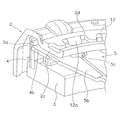
- the diaphragm spring 5 includes an annular elastic portion 5a and a plurality of lever portions 5b extending radially inward from the inner peripheral portion of the annular elastic portion 4a.
- the outer peripheral end of the annular elastic portion 5 a is supported by the second end 4 b of the fulcrum ring 4.
- a slit is formed between the lever portions 5b of the diaphragm spring 5, and an oval hole 5c is formed in the outer peripheral portion of the slit.
- a push-type release device (not shown) is in contact with the tip of the lever portion 5b of the diaphragm spring 5.
- This release device is a device for moving the tip of the lever portion 5b of the diaphragm spring 5 in the axial direction to release the urging force to the pressure plate 3.
- the diaphragm spring 5 is supported by the clutch cover 2 by a support member 12 as shown in FIG. This point will be described in more detail.
- the support member 12 is a ring-shaped plate member disposed on the transmission side surface of the flat portion 2 c of the clutch cover 2.
- a plurality of support protrusions 12 a extending radially inward are formed on the inner peripheral portion of the support member 12.
- the plurality of support protrusions 12 a are bent toward the pressure plate 3, and the bent portions pass through the plurality of through holes 2 d formed in the flat portion 2 c of the clutch cover 2.
- the bent portion that penetrates the through hole 2 d further penetrates the oval hole 5 c of the diaphragm spring 5.
- tip of the protrusion 12a for support is bend
- the wear amount detection mechanism 6 is disposed at a plurality of locations on the outer peripheral portion of the fulcrum ring 4.
- the wear amount detection mechanism 6 is a mechanism for detecting that the wear amount of the friction member constituting the clutch disk assembly has reached a predetermined amount, and includes a movement detection member 15, a cover side detection member 16, and a first coil.
- a spring 17 and a leaf spring 18 are provided.
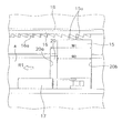
- the movement detection member 15 is a substantially rectangular plate and is disposed in a recess 20 formed on the outer periphery of the fulcrum ring 4.
- the concave portion 20 has a width W1 in the circumferential direction, and the width W1 of the concave portion 20 is larger than the circumferential width W2 of the movement detecting member 15. Therefore, the movement detection member 15 can move in the circumferential direction within the range of (W1-W2).
- Two end teeth (second meshing portions) 15a projecting in the axial direction are formed on the end surface of the movement detection member 15 on the transmission side (upper side in FIG. 5), and the end surface on the opposite side is an inclined surface 15b.
- the inclined surface 15b has the same inclination (in the opposite direction) as the inclined surface of the sliding portion 10 formed in the annular groove 3a of the pressure plate 3, and both inclined surfaces are in contact with each other.
- the cover side detection member 16 is a belt-like and arc-shaped plate, and is supported by a rivet 22 on the pressure plate side surface of the clutch cover 2.
- the pressure plate side surface of the cover side detection member 16 faces the surface on which the teeth 15a of the movement detection member 15 are formed, and a plurality of teeth 16a (first meshing portions) are formed on this surface. .
- the plurality of teeth 16 a of the cover side detection member 16 can be engaged with the teeth 15 a of the movement detection member 15, respectively.
- the first coil spring 17 is a member that urges the movement detection member 15 in the circumferential direction. One end of the first coil spring 17 is engaged with a cut-and-raised portion 15 c formed on the movement detection member 15, and the other end is engaged with the pressure plate 3. It is stopped (the locking part to the pressure plate 3 is omitted). The first coil spring 17 causes the movement detection member 15 to move in the direction R1 in FIG. 5 in the recess 20 of the fulcrum ring 4 when the engagement with the cover side detection member 16 is released.
- the leaf spring 18 is disposed between the cover side detection member 16 and the clutch cover 2, and is supported on the clutch cover 2 by the rivet 22 together with the cover side detection member 16.
- the leaf spring 18 has substantially the same length and width as the cover side detection member 16.
- both end portions of the leaf spring 18 in the longitudinal direction are in contact with the surface of the clutch cover 2.
- the both end portions are separated from the cover side detection member 16, and the portions other than both end portions are separated from the clutch cover 2 by a predetermined distance and are in contact with the cover side detection member 16.
- the cover side detection member 16 and the movement detection member 15 are (in more detail) by the restoring force (biasing force).
- the teeth 15a and 16a of both members are pressed against each other.
- the wear tracking mechanism 7 is a mechanism for keeping the posture of the diaphragm spring 5 in the initial posture by following the amount of wear of the friction member, that is, the amount of movement of the movement detecting member 15.
- the wear following mechanism 7 includes sliding portions 10 and 11 formed on the pressure plate 3 and the fulcrum ring 4, respectively, and a plurality of second coil springs 24. is doing.
- the plurality of second coil springs 24 rotate the fulcrum ring 4 in the circumferential direction, and are arranged between the fulcrum ring 4 and the plurality of protrusions 3b formed on the pressure plate 3 as shown in FIG. Has been.
- Each second coil spring 24 has one end locked to the fulcrum ring 4 and the other end locked to the pressure plate 3.
- the movement detecting member 15 is disposed in the concave portion 20 of the fulcrum ring 4, the movement detecting member 15 is at the time when its side end surface collides with one side end surface 20a of the concave portion 20, that is, (W1- Move and stop for W2). This state is shown in FIG.
- the end surface on the flywheel side of the movement detection member 15 is inclined, and the inclined surface 15b moves in the R1 direction along the sliding portion 10 of the pressure plate 3, so that the movement detection member 15 moves in the R1 direction. As a result, it moves to the transmission side (above FIGS. 5 and 6).
- the movement detecting member 15 is engaged with the cover side detecting member 16 again. That is, the movement detection member 15 and the cover side detection member 16 are temporarily disengaged due to wear of the friction member, but are moved by the biasing force of the first coil spring 17 and mesh with adjacent teeth.
- the engagement between the movement detection member 15 and the cover side detection member 16 is shifted by one pitch of the plurality of teeth 16 a of the cover side detection member 16.
- This one pitch corresponds to the difference (W1 ⁇ W2) between the width W1 of the recess 20 of the fulcrum ring 4 and the width W2 of the movement detection member 15.
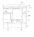
- the fulcrum ring 4 is biased in the R1 direction by the second coil spring 24, when the pressing load on the fulcrum ring 4 is released, the fulcrum ring 4 rotates in the R1 direction with respect to the pressure plate 3. To do. The rotation of the fulcrum ring 4 is stopped when the end surface 20b of the recess 20 of the fulcrum ring 4 comes into contact with the side end surface of the movement detection member 15 as shown in FIG. In this way, the fulcrum ring 4 is rotated by one pitch, that is, (W1-W2) and stopped.
- the fulcrum ring 4 moves in a direction away from the pressure plate 3. That is, the fulcrum ring 4 moves to the transmission side by the wear amount of the friction member (the movement amount of the movement detection member 15). By this movement, the fulcrum ring 4 returns to the initial position before the friction member is worn.
- the pressing load on the fulcrum ring 4 is released as described above, and the fulcrum ring 4, the pressure plate 3 and the movement detection member 15 are movable in the axial direction.
- the movement detection member 15 moves in the axial direction due to vibration, the engagement of the teeth 15a and 16a of the movement detection member 15 and the cover side detection member 16 may be released.
- the cover side detection member 16 is urged toward the movement detection member 15 by the leaf spring 18, so that the two mesh with each other as shown in FIG. It can be prevented from coming off.
- the diaphragm spring 5 presses the fulcrum ring 4.
- the posture of the diaphragm spring 5 is also in the initial state. Accordingly, the pressing load characteristic, and thus the release operation load, are the same as in the initial state.
- the shape of the members constituting the wear amount detection mechanism is not limited to the above embodiment. Any configuration may be used as long as it has a plurality of meshing positions and the meshing position changes according to the wear amount of the friction member.
- the configuration of the wear tracking mechanism may be any configuration as long as it functions to maintain the initial posture of the diaphragm spring, and is not limited to the above embodiment.
- the movement detection member since the movement detection member is always engaged at the engagement position in the wear amount detection mechanism, the member for detecting the wear amount is not displaced by vibration. For this reason, the operation of the wear amount detection mechanism is stable, and accurate wear compensation can always be performed.
Landscapes
- Engineering & Computer Science (AREA)
- General Engineering & Computer Science (AREA)
- Mechanical Engineering (AREA)
- Mechanical Operated Clutches (AREA)
Abstract
Description
図1に本発明の一実施形態によるクラッチカバー組立体1の正面図を示す。また、図2にクラッチカバー組立体1の一部を破断するとともに一部の部材を省略した外観斜視図を示す。このクラッチカバー組立体1は、クラッチオン(動力伝達)時にはエンジンのフライホイールに対してクラッチディスク組立体の摩擦部材を押し付け、またクラッチオフ(動力伝達遮断)時にはその押し付けを解除するための装置である。なお、ここでは、フライホイール及びクラッチディスク組立体は省略している。
クラッチカバー2は、概ね皿形状のプレート部材であり、外周部が例えばボルトによりフライホイールに固定される。クラッチカバー2は、環状のクラッチカバー本体2aと、外周側の円板状部2bと、内周側の平坦部2cと、を有している。円板状部2bは、クラッチカバー本体2aの外周側に形成され、フライホイールの外周部に固定される。平坦部2cは、クラッチカバー本体2aの内周部から半径方向内側へ延びる平坦な部分である。この平坦部2cには、軸方向に貫通する複数の孔2dが形成されている。
プレッシャプレート3は、環状の部材であって、クラッチカバー2のクラッチカバー本体2a内部に配置されている。プレッシャプレート3のフライホイール側(図2において下側)の側面には、クラッチディスク組立体の摩擦部材と摺接する摩擦面が形成されている。また、プレッシャプレート3は、複数のストラッププレート(図示せず)によってクラッチカバー2に連結されており、クラッチカバー2に対して、軸方向には移動可能であるが相対回転不能である。なお、クラッチ連結状態では、ストラッププレートは軸方向にたわんでおり、このストラッププレートのたわみ(復元力)によって、プレッシャプレート3はフライホイールから離れる側に付勢されている。
複数のファルクラムリング4は、それぞれ円弧状の部材、すなわち、環状の部材を円周方向に分割して形成された部材であり、図2及び図3に示すように、軸方向の第1端側4a(フライホイール側)がプレッシャプレート3の環状溝3aに挿入されている。また、ファルクラムリング4の軸方向の第2端側4b(トランスミッション側)は、環状溝3aから突出している。ファルクラムリング4の第1端4aには、図3から明らかなように、円周方向の複数個所において摺動部11が形成されている。この摺動部11は、プレッシャプレート3の環状溝3aの底面に形成された摺動部10の傾斜面に当接しており、円周方向(図3のR1方向)に向かってその高さがより低くなるように傾斜する傾斜面を有している。
ダイヤフラムスプリング5は、プレッシャプレート3とクラッチカバー2との間に配置された円板状部材であり、図4にその一部を示す。このダイヤフラムスプリング5は、環状弾性部5aと、環状弾性部4aの内周部から径方向内側に延びる複数のレバー部5bとから構成されている。環状弾性部5aの外周端はファルクラムリング4の第2端4bに支持されている。また、ダイヤフラムスプリング5のレバー部5b間はスリットになっており、スリットの外周部には小判状の孔5cが形成されている。
摩耗量検出機構6は、図2、図5及び図6に示すように、ファルクラムリング4の外周部の複数個所に配置されている。この摩耗量検出機構6は、クラッチディスク組立体を構成する摩擦部材の摩耗量が所定量に達したことを検出する機構であり、移動検出部材15と、カバー側検出部材16と、第1コイルスプリング17と、板ばね18と、を有している。
摩耗追従機構7は、摩擦部材の摩耗量、すなわち移動検出部材15の移動量に追従させて、ダイヤフラムスプリング5の姿勢を初期の姿勢に保つための機構である。この摩耗追従機構7は、複数のファルクラムリング4に加えて、前述のプレッシャプレート3及びファルクラムリング4のそれぞれに形成された摺動部10,11と、複数の第2コイルスプリング24と、を有している。
クラッチオン(連結)状態では、ダイヤフラムスプリング5の押圧荷重は、ファルクラムリング4を介してプレッシャプレート3に作用し、これによりクラッチディスク組立体の摩擦部材はプレッシャプレート3とフライホイールとの間に挟持されている。このとき、図5及び図6に示すように、移動検出部材15の歯15aはカバー側検出部材16の歯16aに噛み合っている。
(1)摩耗量検出機構6では、移動検出部材15及びカバー側検出部材16の歯15a,16aが常に噛み合っているので、振動によって摩耗量検出結果が変化するのを抑えることができる。このため、摩耗量検出機構6の作動が安定し、正確な摩耗補償を行うことができる。
本発明は以上のような実施形態に限定されるものではなく、本発明の範囲を逸脱することなく種々の変形又は修正が可能である。
2 クラッチカバー
3 プレッシャプレート
4 ファルクラムリング
5 ダイヤフラムスプリング
6 摩耗量検出機構
7 摩耗追従機構
10,11 摺動部
15 移動検出部材
16 カバー側検出部材
17 第1コイルスプリング(第1付勢部材)
18 板ばね18(第3付勢部材)
24 第2コイルスプリング(第2付勢部材)
Claims (6)
- エンジンのフライホイールにクラッチディスク組立体の摩擦部材を押し付け及び押し付け解除するためのクラッチカバー組立体であって、
前記フライホイールに固定されるクラッチカバーと、
前記クラッチカバーに相対回転不能に連結され、前記フライホイールに前記摩擦部材を押圧するためのプレッシャプレートと、
前記クラッチカバーに支持されるとともに、前記プレッシャプレートを前記フライホイール側に押圧するための押圧部材と、
複数の噛み合い位置を有する機構であり、前記摩擦部材が所定の摩耗量に到達したときに第1噛み合い位置での噛み合いを解除して第2噛み合い位置に移動する移動検出部材を有する摩耗量検出機構と、
前記移動検出部材の移動量に応じて、前記押圧部材を初期姿勢側に移動させるための摩耗追従機構と、
を備えたクラッチカバー組立体。 - 前記摩耗量検出機構は、前記クラッチカバーに支持され、複数の第1噛み合い部を有するカバー側検出部材をさらに有し、
前記移動検出部材は、前記プレッシャプレートとともに移動するとともに、前記複数の第1噛み合い部に噛み合い可能な第2噛み合い部を有し、前記摩擦部材が所定の摩耗量に到達したときに前記第2噛み合い部の前記第1噛み合い部への噛み合いが解除される、
請求項1に記載のクラッチカバー組立体。 - 前記摩耗量検出機構は、前記複数の第1噛み合い部が配列された方向に前記移動検出部材を付勢し、前記両噛み合い部の前記第1噛み合い位置での噛み合いが解除されたときに前記移動検出部材を前記第2噛み合い位置に移動させる第1付勢部材をさらに有する、請求項2に記載のクラッチカバー組立体。
- 前記摩耗追従機構は、
それぞれ前記プレッシャプレートに軸方向に移動自在に支持され、前記ダイヤフラムスプリングによって前記プレッシャプレート側に押圧される複数のファルクラムリングと、
前記プレッシャプレート及び前記ファルクラムリングのそれぞれに形成され、互いに当接して摺動する摺動部と、
複数の前記ファルクラムリングを円周方向に付勢して複数の前記ファルクラムリングを前記プレッシャプレートに対して相対回転させる第2付勢部材と、
を有し、
前記摺動部は円周方向に沿って傾斜する傾斜面からなり、
前記第2付勢部材は、複数の前記ファルクラムリングを前記移動検出部材の移動量に応じて回転させて複数の前記ファルクラムリングを前記プレッシャプレートから離す方向に移動させる、
請求項3に記載のクラッチカバー組立体。 - 前記摩耗量検出機構は、前記両噛み合い部を互いに圧接させるための第3付勢部材をさらに有している、請求項4に記載のクラッチカバー組立体。
- 前記移動検出部材は、軸方向一端側に前記プレッシャプレートの傾斜面に沿った傾斜を有し、かつ前記傾斜面に当接する傾斜面を有し、
前記第1付勢部材は、前記移動検出部材の傾斜面を前記プレッシャプレートの傾斜面に沿って移動させて、前記第2噛み合い部を前記第1噛み合い部に噛み合わせる、
請求項5に記載のクラッチカバー組立体。
Priority Applications (3)
| Application Number | Priority Date | Filing Date | Title |
|---|---|---|---|
| CN201180029773.7A CN102959263B (zh) | 2010-07-06 | 2011-06-09 | 离合器盖组件 |
| DE112011102279T DE112011102279T5 (de) | 2010-07-06 | 2011-06-09 | Kupplungsdeckelanordnung |
| US13/805,066 US8967354B2 (en) | 2010-07-06 | 2011-06-09 | Clutch cover assembly |
Applications Claiming Priority (2)
| Application Number | Priority Date | Filing Date | Title |
|---|---|---|---|
| JP2010-153630 | 2010-07-06 | ||
| JP2010153630A JP4962996B2 (ja) | 2010-07-06 | 2010-07-06 | クラッチカバー組立体 |
Publications (1)
| Publication Number | Publication Date |
|---|---|
| WO2012005078A1 true WO2012005078A1 (ja) | 2012-01-12 |
Family
ID=45441064
Family Applications (1)
| Application Number | Title | Priority Date | Filing Date |
|---|---|---|---|
| PCT/JP2011/063282 Ceased WO2012005078A1 (ja) | 2010-07-06 | 2011-06-09 | クラッチカバー組立体 |
Country Status (5)
| Country | Link |
|---|---|
| US (1) | US8967354B2 (ja) |
| JP (1) | JP4962996B2 (ja) |
| CN (1) | CN102959263B (ja) |
| DE (1) | DE112011102279T5 (ja) |
| WO (1) | WO2012005078A1 (ja) |
Families Citing this family (3)
| Publication number | Priority date | Publication date | Assignee | Title |
|---|---|---|---|---|
| MX388486B (es) * | 2015-10-05 | 2025-03-20 | Schaeffler Technologies Ag | Embrague de fricción. |
| FR3050492B1 (fr) * | 2016-04-21 | 2018-04-27 | Valeo Embrayages | Dispositif d'embrayage a rattrapage d'usure, notamment pour vehicule automobile |
| US11441615B2 (en) | 2018-09-13 | 2022-09-13 | Eaton Intelligent Power Limited | Clutch adjustment system with wear resistant features for back driving prevention |
Citations (3)
| Publication number | Priority date | Publication date | Assignee | Title |
|---|---|---|---|---|
| JPH0353628U (ja) * | 1989-09-29 | 1991-05-23 | ||
| JP2000002267A (ja) * | 1998-06-17 | 2000-01-07 | Exedy Corp | クラッチカバー組立体 |
| JP2006144819A (ja) * | 2004-11-16 | 2006-06-08 | Aisin Seiki Co Ltd | クラッチ装置 |
Family Cites Families (11)
| Publication number | Priority date | Publication date | Assignee | Title |
|---|---|---|---|---|
| US4207972A (en) * | 1978-05-26 | 1980-06-17 | Borg-Warner Corporation | Automatic wear compensator for Belleville spring clutches |
| JPH0532664Y2 (ja) * | 1989-07-20 | 1993-08-20 | ||
| KR100326408B1 (ko) * | 1992-12-22 | 2002-10-31 | 룩라멜렌운트쿠플룽스바우베타일리궁스카게 | 마찰클러치 |
| US5566804A (en) * | 1994-06-21 | 1996-10-22 | Dana Corporation | Automatically adjusting friction torque device |
| JP3389457B2 (ja) | 1996-12-13 | 2003-03-24 | 株式会社エクセディ | クラッチカバー組立体 |
| BR9901492A (pt) * | 1998-06-18 | 2000-01-04 | Mannesmann Sachs Ag | Módulo de placas de pressão.. |
| JP2003028193A (ja) | 2001-07-12 | 2003-01-29 | Exedy Corp | クラッチカバー組立体 |
| JP3943950B2 (ja) * | 2002-02-18 | 2007-07-11 | 株式会社エクセディ | クラッチカバー組立体 |
| DE602005011231D1 (de) | 2004-11-12 | 2009-01-08 | Aisin Seiki | Kupplungsnachstellvorrichtung |
| US8042673B2 (en) * | 2008-11-26 | 2011-10-25 | Eaton Corporation | Axially compliant clutch departure control sleeve |
| JP4834783B1 (ja) * | 2010-09-24 | 2011-12-14 | 株式会社エクセディ | クラッチカバー組立体 |
-
2010
- 2010-07-06 JP JP2010153630A patent/JP4962996B2/ja active Active
-
2011
- 2011-06-09 US US13/805,066 patent/US8967354B2/en not_active Expired - Fee Related
- 2011-06-09 DE DE112011102279T patent/DE112011102279T5/de not_active Ceased
- 2011-06-09 CN CN201180029773.7A patent/CN102959263B/zh not_active Expired - Fee Related
- 2011-06-09 WO PCT/JP2011/063282 patent/WO2012005078A1/ja not_active Ceased
Patent Citations (3)
| Publication number | Priority date | Publication date | Assignee | Title |
|---|---|---|---|---|
| JPH0353628U (ja) * | 1989-09-29 | 1991-05-23 | ||
| JP2000002267A (ja) * | 1998-06-17 | 2000-01-07 | Exedy Corp | クラッチカバー組立体 |
| JP2006144819A (ja) * | 2004-11-16 | 2006-06-08 | Aisin Seiki Co Ltd | クラッチ装置 |
Also Published As
| Publication number | Publication date |
|---|---|
| US8967354B2 (en) | 2015-03-03 |
| US20130092500A1 (en) | 2013-04-18 |
| DE112011102279T5 (de) | 2013-05-29 |
| CN102959263B (zh) | 2015-05-13 |
| JP4962996B2 (ja) | 2012-06-27 |
| JP2012017754A (ja) | 2012-01-26 |
| CN102959263A (zh) | 2013-03-06 |
Similar Documents
| Publication | Publication Date | Title |
|---|---|---|
| US20100224460A1 (en) | Clutch cover assembly | |
| JP5974450B2 (ja) | クラッチ装置 | |
| JP4962996B2 (ja) | クラッチカバー組立体 | |
| JP4834783B1 (ja) | クラッチカバー組立体 | |
| US20130140125A1 (en) | Clutch cover assembly | |
| JP5008757B2 (ja) | クラッチカバー組立体 | |
| JP3317630B2 (ja) | 摩擦クラッチ | |
| JP4930786B2 (ja) | クラッチレリーズ軸受装置 | |
| JP4472465B2 (ja) | 車両用クラッチ装置 | |
| JP5083529B2 (ja) | クラッチレリーズ軸受装置 | |
| JP3317636B2 (ja) | 摩擦クラッチ | |
| WO2017141699A1 (ja) | クラッチカバー組立体 | |
| JP4715997B2 (ja) | クラッチレリーズ軸受装置 | |
| JP2011153665A (ja) | クラッチレリーズ軸受装置 | |
| JP2018112247A (ja) | クラッチ装置 | |
| JP2006090360A (ja) | クラッチレリーズ軸受装置 | |
| JP2005195132A (ja) | クラッチレリーズ軸受装置 |
Legal Events
| Date | Code | Title | Description |
|---|---|---|---|
| WWE | Wipo information: entry into national phase |
Ref document number: 201180029773.7 Country of ref document: CN |
|
| 121 | Ep: the epo has been informed by wipo that ep was designated in this application |
Ref document number: 11803414 Country of ref document: EP Kind code of ref document: A1 |
|
| WWE | Wipo information: entry into national phase |
Ref document number: 13805066 Country of ref document: US |
|
| WWE | Wipo information: entry into national phase |
Ref document number: 112011102279 Country of ref document: DE Ref document number: 1120111022794 Country of ref document: DE |
|
| 122 | Ep: pct application non-entry in european phase |
Ref document number: 11803414 Country of ref document: EP Kind code of ref document: A1 |