WO2012001797A1 - フリーザー装置 - Google Patents
フリーザー装置 Download PDFInfo
- Publication number
- WO2012001797A1 WO2012001797A1 PCT/JP2010/061212 JP2010061212W WO2012001797A1 WO 2012001797 A1 WO2012001797 A1 WO 2012001797A1 JP 2010061212 W JP2010061212 W JP 2010061212W WO 2012001797 A1 WO2012001797 A1 WO 2012001797A1
- Authority
- WO
- WIPO (PCT)
- Prior art keywords
- cold air
- pressure chamber
- space
- conveyor belt
- housing
- Prior art date
- Legal status (The legal status is an assumption and is not a legal conclusion. Google has not performed a legal analysis and makes no representation as to the accuracy of the status listed.)
- Ceased
Links
Images







Classifications
-
- F—MECHANICAL ENGINEERING; LIGHTING; HEATING; WEAPONS; BLASTING
- F25—REFRIGERATION OR COOLING; COMBINED HEATING AND REFRIGERATION SYSTEMS; HEAT PUMP SYSTEMS; MANUFACTURE OR STORAGE OF ICE; LIQUEFACTION SOLIDIFICATION OF GASES
- F25D—REFRIGERATORS; COLD ROOMS; ICE-BOXES; COOLING OR FREEZING APPARATUS NOT OTHERWISE PROVIDED FOR
- F25D13/00—Stationary devices, e.g. cold-rooms
- F25D13/06—Stationary devices, e.g. cold-rooms with conveyors carrying articles to be cooled through the cooling space
- F25D13/067—Stationary devices, e.g. cold-rooms with conveyors carrying articles to be cooled through the cooling space with circulation of gaseous cooling fluid
-
- F—MECHANICAL ENGINEERING; LIGHTING; HEATING; WEAPONS; BLASTING
- F25—REFRIGERATION OR COOLING; COMBINED HEATING AND REFRIGERATION SYSTEMS; HEAT PUMP SYSTEMS; MANUFACTURE OR STORAGE OF ICE; LIQUEFACTION SOLIDIFICATION OF GASES
- F25D—REFRIGERATORS; COLD ROOMS; ICE-BOXES; COOLING OR FREEZING APPARATUS NOT OTHERWISE PROVIDED FOR
- F25D13/00—Stationary devices, e.g. cold-rooms
- F25D13/06—Stationary devices, e.g. cold-rooms with conveyors carrying articles to be cooled through the cooling space
-
- F—MECHANICAL ENGINEERING; LIGHTING; HEATING; WEAPONS; BLASTING
- F25—REFRIGERATION OR COOLING; COMBINED HEATING AND REFRIGERATION SYSTEMS; HEAT PUMP SYSTEMS; MANUFACTURE OR STORAGE OF ICE; LIQUEFACTION SOLIDIFICATION OF GASES
- F25D—REFRIGERATORS; COLD ROOMS; ICE-BOXES; COOLING OR FREEZING APPARATUS NOT OTHERWISE PROVIDED FOR
- F25D13/00—Stationary devices, e.g. cold-rooms
- F25D13/06—Stationary devices, e.g. cold-rooms with conveyors carrying articles to be cooled through the cooling space
- F25D13/062—Stationary devices, e.g. cold-rooms with conveyors carrying articles to be cooled through the cooling space with refrigerated conveyors
-
- F—MECHANICAL ENGINEERING; LIGHTING; HEATING; WEAPONS; BLASTING
- F25—REFRIGERATION OR COOLING; COMBINED HEATING AND REFRIGERATION SYSTEMS; HEAT PUMP SYSTEMS; MANUFACTURE OR STORAGE OF ICE; LIQUEFACTION SOLIDIFICATION OF GASES
- F25D—REFRIGERATORS; COLD ROOMS; ICE-BOXES; COOLING OR FREEZING APPARATUS NOT OTHERWISE PROVIDED FOR
- F25D17/00—Arrangements for circulating cooling fluids; Arrangements for circulating gas, e.g. air, within refrigerated spaces
- F25D17/04—Arrangements for circulating cooling fluids; Arrangements for circulating gas, e.g. air, within refrigerated spaces for circulating air, e.g. by convection
- F25D17/06—Arrangements for circulating cooling fluids; Arrangements for circulating gas, e.g. air, within refrigerated spaces for circulating air, e.g. by convection by forced circulation
-
- F—MECHANICAL ENGINEERING; LIGHTING; HEATING; WEAPONS; BLASTING
- F25—REFRIGERATION OR COOLING; COMBINED HEATING AND REFRIGERATION SYSTEMS; HEAT PUMP SYSTEMS; MANUFACTURE OR STORAGE OF ICE; LIQUEFACTION SOLIDIFICATION OF GASES
- F25D—REFRIGERATORS; COLD ROOMS; ICE-BOXES; COOLING OR FREEZING APPARATUS NOT OTHERWISE PROVIDED FOR
- F25D2400/00—General features of, or devices for refrigerators, cold rooms, ice-boxes, or for cooling or freezing apparatus not covered by any other subclass
- F25D2400/32—Removal, transportation or shipping of refrigerating devices from one location to another
Definitions
- the present invention relates to a freezer apparatus capable of continuously cooling or freezing while transporting an object to be cooled, particularly an object to be cooled such as fresh food by a conveyor belt in a cooling space, and in particular, the housing is compacted and disassembled
- the present invention relates to a freezer apparatus which can be stored in a container without using it.
- the conventional food freezing apparatus is provided with a conveyor for transporting frozen food into the freezing chamber, and a plurality of cold air circulating devices including a refrigerator unit, an air cooler and a blower are provided in the upper space of the freezing chamber.
- the cold air is convectively circulated toward the conveying surface of the conveyor.
- the frozen food can be continuously frozen while being transported by the conveyor, and the processing efficiency can be improved.
- the cold air collision jet is applied to the frozen food to improve the cold air effect.
- Patent Document 1 The applicant has proposed such a continuous transfer type freezer apparatus (Patent Document 1).
- This device sprays a collision jet of cold air from the slit nozzle having a funnel-shaped cross section to the frozen food to form a thin film flow of cold air in close contact with the surface of the frozen food by the Coanda effect, and a high cooling effect can be obtained. It is something like that.
- the outline of the apparatus disclosed in Patent Document 1 will be described below with reference to FIGS. 14 and 15. FIG.
- a cooling space s is formed inside a closed housing 102 formed of a heat insulating wall 104.
- the partition wall of the sealed housing 102 is provided with openable and closable inspection doors 106, 108 and 110.
- a conveyor belt 112 for transporting the frozen food w is disposed in the sealed housing 102.
- the conveyor belt 112 is an endless belt composed of a forward pass 112 a and a return pass 112 b.
- An upper cold air injection unit 114 is provided above the forward path 112a, and a lower cold air injection unit 116 is provided below the forward path 112a.
- An air cooler 118 is provided inside the side wall of the sealed housing 102, and a blower (sirocco fan) 120 is provided above the air cooler 118.
- the air cooler 118 is supplied with a refrigerant or brine from a refrigerator unit (not shown) provided outside the sealed housing 102 to cool the air in the cold storage.
- the cooled internal air c is sent to the upper cold air injection unit 114 and the lower cold air injection unit 116 by the blower 120.
- the upper cold air jet unit 114 is integrally provided with a slit nozzle 124 having a plurality of funnel-shaped cross sections aligned in the conveyance direction a of the food to be frozen w below the nozzle unit 122.
- Each slit nozzle 124 extends in a direction perpendicular to the transport direction a of the food to be frozen w, and includes an accelerating portion 126 having a funnel-shaped cross section and a straightening portion (progression portion) 128 having the same flow passage area. It is configured.
- the jet nozzle provided at the tip of the flow straightening unit 128 forms a slit-like opening directed in a direction perpendicular to the conveyance direction a.
- the cold air c sent to the upper cold air injection unit 114 is accelerated by the acceleration unit 126, rectified by the rectification unit 128, and then perpendicular to the frozen food w placed on the belt surface of the forward path 112a of the conveyor belt 112. It is sprayed.
- the collision jet r sprayed to the frozen food w forms a thin film flow t in close contact with the surface of the frozen food w by the co-under effect, so that the cooling effect of the frozen food w can be improved.
- the nozzle unit 130 is integrally provided with a plurality of slit nozzles 132 consisting of an acceleration unit 134 and a flow straightening unit 136 having a chevron cross section.
- the collision jet r is injected toward the back of the body.
- the cool air after being subjected to the cooling of the frozen food w is discharged in the width direction of the conveyor belt through the exhaust space e formed between the slit nozzles and forms a circulating flow to the air cooler 118 thereafter.
- the belt structure of the conveyor belt 112 has a large number of fine holes to improve the flowability of cold air r blown from above and below to enhance the cooling effect, and heat transferability like stainless steel. There is a case where the food to be frozen w is cooled by the belt body cooled by the cold air r so as to enhance the cooling effect.
- the conveyor belt for transporting the object to be cooled needs a width dimension of a certain degree or more from the viewpoint of processing capacity.
- the conventional freezer apparatus has the air cooler 118 disposed in the lateral direction of the conveyor belt, so the width of the housing is increased.
- the air blower 120 is arrange
- the height of the housing can not but be increased accordingly.
- a duct for forming a cold air circulation flow is extended to the left and right.
- the dimensions of the internal volume of a container which can be transported by a truck or the like are 40 feet (12 m) long ⁇ 2.3 m wide ⁇ 2.5 m high, but the conventional freezer device It could not be accommodated in a large size container. Therefore, it was disassembled, transported, and reassembled on site, so time wasted and the performance after reassembly was not stable.
- the lower cold air injection portion is provided with a slit nozzle having a complicated structure, the cleaning property is poor, and there are some problems in the maintenance property and the sanitary property.
- a large positive pressure space which is higher in pressure than external air, is provided above the cooling space, positive pressure is applied to the inspection door provided facing the positive pressure space. Therefore, there is a danger that opening the inspection door during operation is dangerous and the durability of the inspection door is reduced.
- the thickness of the conveyor belt is made thicker (about 1 mm) in consideration of metal fatigue of the belt body made of steel belt etc., but this increases the thermal load of the belt body and makes it difficult to cool, The cost of the conveyor belt also increases.
- the meandering prevention apparatus is provided in the return path of the conveyor belt, there existed a case where this meandering prevention apparatus freezed and could not exhibit the original function.
- a first object of the present invention to realize a freezer device which is compact in housing and can be accommodated in a container, thereby eliminating disassembly and transportation and reassembly in the field.
- the second object is to reduce the positive pressure space higher than the outside air in the cooling space, thereby eliminating the risk of opening and closing the inspection door and improving the durability of the inspection door.
- the freezer apparatus of the present invention is A housing for forming a horizontally long cooling space surrounded by heat insulating walls, a conveyor belt for transporting an object to be cooled disposed in the longitudinal direction of the cooling space, an air cooler for forming a cold air circulation flow in the cooling space, And a cold air circulation system comprising a blower, wherein the object to be cooled can be subjected to continuous processing of cooling or freezing,
- a negative pressure chamber provided in the upper region of the cross section, the housing having a rectangular cross section, the air cooler and the blower being disposed adjacent to each other to form a negative pressure space;
- cold air is supplied from the blower to form a positive pressure space, and the conveyor belt and a cold air jet portion for jetting cold air from the vertical direction toward the conveyor belt are provided.
- Positive pressure chamber It is provided in the side area of the negative pressure chamber and the positive pressure chamber, and the positive pressure chamber receives cold air after being used for cooling the object to be cooled, and returns the received cold air to the negative pressure chamber. And a maintenance space under normal pressure to form
- the blower and the air cooler are disposed adjacent to each other in the negative pressure chamber, the space of the negative pressure chamber is reduced, the housing has a rectangular cross section, and the negative pressure chamber is disposed in the upper part of the space inside the housing, By arranging a positive pressure chamber below it, the negative pressure chamber can be reduced in the width direction of the housing.
- a maintenance space at normal pressure is disposed on the side of the negative pressure chamber and the positive pressure chamber, and a return flow path for cold air supplied from the negative pressure chamber to the positive pressure chamber is formed in this maintenance space. The pressure loss of the cold air circulation flow is reduced and a large positive pressure space is not required.
- a cold air port for supplying cold air from the negative pressure chamber to the positive pressure chamber is received near the side wall of the housing away from the maintenance space, and the lower cold air injection portion is vertically below the cold air port. It is preferable that an air supply space for supplying cold air be formed. As a result, it is possible to secure a cool air flow path for supplying cool air to the cool air jet portion in the positive pressure chamber without expanding the width dimension of the housing. Furthermore, since a smooth circulating flow of cold air can be formed in the lower positive pressure chamber and the pressure loss of the cold air circulating flow can be reduced, the power of the blower can be reduced.
- the housing side wall facing the maintenance space may be provided with an open / close door so that the operator can enter the maintenance space.
- the inspection in the housing becomes easy, and since the open / close door is provided facing the maintenance space under normal pressure, the danger when the open / close door is opened can be eliminated.
- the durability of the open / close door can be improved.
- the conveyor belt is disposed in the positive pressure chamber, and an outward path whose both ends are conducted outside the cooling space, and a return path whose both ends are connected to the outward path and are disposed below the outside of the cooling space
- the rotary belt may be provided outside the cooling space, and the conveyor belt may be wound around the outer peripheral surface of the rotary drum to support and convey the conveyor belt.
- the return path is disposed at the lower side outside the cooling space, the installation space of the positive pressure chamber can be reduced accordingly. This allows the height dimension of the housing to be reduced, which makes the housing more compact and easier to accommodate in the container.
- the meandering prevention device does not freeze and can exhibit the traditional function.
- the rotary drum is provided outside the cooling space, the installation space of the rotary drum is not restricted, and the diameter of the rotary drum can be increased. Therefore, since metal fatigue of the belt can be alleviated, the thickness of the belt can be reduced, which can reduce the heat load on the belt and reduce the cost of the belt.
- the lower cold air jet portion disposed below the conveyor belt may have a function of only cooling the belt body. . Therefore, it is not necessary to use the slit nozzle which has a funnel-shaped cross section with long cold air reach distance especially in a lower cold air injection part. Therefore, since the installation space of the lower cold air injection part can be reduced, the height dimension of the housing can be reduced, and the container can be easily accommodated.
- the housing forms a long cooling space surrounded by the heat insulation wall, the conveyer belt for transporting the object to be cooled disposed in the longitudinal direction of the cooling space, and the cold air circulation flow to the cooling space.
- a cold air circulation system comprising an air cooler and a blower, wherein the housing has a rectangular cross section, and the freezer has a continuous process of cooling or freezing for the object to be cooled.
- An air cooler and a blower are disposed adjacent to each other to form a negative pressure chamber, and a negative pressure chamber is provided in the lower region of the negative pressure chamber, and cold air is supplied from the blower and positive pressure is provided.
- a positive pressure chamber provided with a space and a cold air jet portion for injecting cold air from the vertical direction toward the conveyor belt and the conveyor belt, and provided in a side area of the negative pressure chamber and the positive pressure chamber.
- Cooling of the object to be cooled in the positive pressure chamber And a normal maintenance space for forming a return flow of cold air for returning the received cold air to the negative pressure chamber, thereby reducing the width dimension and the height dimension of the housing. It is possible to realize a freezer device that can be stored in a container without disassembling.
- FIG. 4 is a cross-sectional plan view taken along the line AA in FIG. 3; It is a perspective view of the cold air injection mechanism of the said freezer apparatus. It is a front view which shows the drive part of the metal belt drive of the said freezer apparatus. It is a side view of the drive part of FIG. It is a front view which shows the driven part of the said metal belt drive device. It is a side view of the said follower part. It is a perspective view when accommodating the said freezer apparatus in a container.
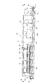
- FIGS. 1 to 4 One embodiment of the device of the present invention will be described with reference to FIGS. First, the overall configuration of the freezer apparatus 10 according to the present embodiment will be described with reference to FIGS. 1 to 4.
- the freezer apparatus 10 is comprised with the housing 12 which forms the laterally long cooling space enclosed by the heat insulation wall. It should be noted that in FIG. 2 the front sidewall and top wall of the housing 12 have been removed so that the internal structure can be seen. Also, in FIG. 3, the front sidewall of the left half of the housing 12 is removed for the same purpose.
- the housing 12 has a closed structure except for the inlet opening 14 of the conveyor belt provided in the inlet wall 12 c and the outlet opening 16 of the conveyor belt provided in the outlet wall 12 d.
- a plurality of monitoring windows 18 are disposed in the longitudinal direction of the housing 12 on the front wall 12 a.
- the rear wall 12 b is provided with a plurality of open / close doors 20 so that the operator can enter the housing 12.
- the upper wall 12e of the housing 12 is a closed wall, through which a supply pipe 22 for supplying a refrigerant or brine from a refrigerator unit (not shown) to the air cooler and an exhaust pipe 24 for discharging the refrigerant or brine pass There is.
- the bottom wall 12 f of the housing 12 is supported by the legs 26 at a distance from the floor surface F.
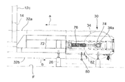
- a conveying device 30 for conveying the frozen food w into the housing 12 is provided at the lower part of the housing 12.
- the conveying device 30 comprises an endless conveyor belt 32 and rotating drums 34 and 36 for driving the conveyor belt 32.
- the conveyor belt 32 is formed of a thin stainless steel plate having good heat transferability, and has a closed structure without a cold air vent.
- the conveyor belt 32 is wound around the driven drum 34 outside the inlet wall 12 c and around the driving drum 36 outside the outlet wall 12 d.
- the forward path 32a of the conveyor belt 32 has a conveying surface horizontally disposed, penetrates through the inlet opening 14 and the outlet opening 16 into the housing 12, and moves in the arrow a direction.
- the return path 32b is disposed in the space below the bottom wall 12f.
- the housing 12 has a rectangular cross-section.
- the inside of the housing 12 is divided by the partition walls 38 and 40 into a negative pressure chamber 42, a positive pressure chamber 44, and a maintenance space 46 disposed on the side thereof.
- the negative pressure chamber 42 is provided in the upper region of the housing 12, and the air cooler 48 is fixed to the upper surface of the partition wall 38.
- the air cooler 48 is connected to a refrigerator unit (not shown) disposed separately from the housing 12 via the supply and discharge pipes 22 and 24.
- a circular air passage 38a is formed adjacent to the air cooler 48.
- a cylindrical casing 50 is attached to the air passage 38a, and an axial fan 52 and its drive motor 54 are provided in the casing 50.
- two units of air coolers 48 are provided in the longitudinal direction of the housing 12, and four axial flow fans 52 are provided in the longitudinal direction of the housing 12 per unit. Then, the internal air cooled by the air cooler 48 is sent from the air passage 38 a to the positive pressure chamber 44 by the axial fan 52. Therefore, the negative pressure chamber 42 has a negative pressure atmosphere.
- the positive pressure chamber 44 is provided in the lower region of the negative pressure chamber 42, and both are partitioned by the partition wall 38.
- the forward passage 32a of the conveyor belt 32 is disposed in the horizontal direction.
- the outward path 32a is disposed at a predetermined height by a plurality of support bars 56 provided in the width direction.
- Support frames 58 and 60 are disposed in the longitudinal direction of the housing 12 at the upper side of the forward path 32 a of the conveyor belt 32.
- An upper cold air injection unit 62 is provided above the outward passage 32 a in the conveyance direction a of the conveyor belt 32 along the outward passage 32 a.
- the upper cold air injection unit 62 is composed of a plurality of nozzle units 64.
- the lower part of the nozzle unit 64 is integrally formed four slit nozzles 64a having the same structure as the slit nozzle 124 shown in FIG.
- the flange 64b is formed.
- the flange 64b is mounted on and supported by the support frames 58, 60.
- the lower end of the slit nozzle 64a forms a slit-like cold air jet outlet disposed in the width direction of the forward path 32a.
- a lower cold air injection unit 66 is provided along the forward path 32a.
- the lower cold air injection part 66 is comprised by the box-shaped casing 68 which has the cold air flow inlet 68a in one side.
- the box-like casing 68 is fixed to the upper surface of the bottom wall 12f, and the upper face 68b of the box-like casing 68 is formed into a flat surface, and a large number of circular cold air outlets 70 are bored.
- the upper surface 68 b and the bottom wall 12 f are inclined downward and substantially parallel to each other toward the maintenance space 46.
- a frame 72 is connected to the inlet wall 12 c of the housing 12 and supported horizontally by the legs 26.
- the cylindrical driven drum 34 is disposed horizontally, and the conveyor belt 32 is wound around the driven drum 34.
- the surface of the driven drum 34 is coated with a rubber material. Both ends of the rotary shaft 34 a of the driven drum 34 are rotatably supported by bearings 74.
- the bearing 74 is slidably supported by the frame 72 in the direction of arrow a or b, and is attached to the frame 72 via a coil spring 76. Thereby, the driven drum 34 can move in the direction of the arrow a or b, and the tension of the conveyor belt 32 can be adjusted.
- a reinforcing bar 79, a support bar 80 for supporting the return path 32b of the conveyor belt 32, and a guide bar 82 for guiding the return path 32b are provided between the frames 72.
- the frame 84 is fixed to the outlet wall 12d, and the rotation shaft 36a of the drive drum 36 is rotatably supported by the frame 84 via the bearing 86. Further, a drive motor 88 for driving the rotation shaft 36 a is attached to the frame 84.
- the conveyor belt 32 is wound around the drive drum 36, and the conveyor belt 32 moves in the direction of the arrow a or b by the rotation of the drive drum 36. Similar to the driven drum 34, a rubber film is coated on the outer peripheral surface of the drive drum 36.
- a rubber projection 33 having a tapered trapezoidal cross section is joined by vulcanization.
- a pulley 77 having a recess 77 a on the outer peripheral surface is joined to one end surface of the driven drum 34.
- the recessed portion 77 a and the end surface of the driven drum 34 form a recessed groove fitted to the rubber protrusion 33.
- a pulley 77 for forming the recess 77 a is also attached to one end face of the drive drum 36.
- the rubber projection 33 and the pulley 77 constitute a meandering prevention device 78.
- the conveyor belt 32 travels while the rubber projection 33 is loosely fitted in the recess 77 a, thereby preventing the conveyor belt 32 from meandering.
- the operator places the frozen food w on the belt surface of the forward path 32 a of the conveyor belt 32 on the inlet wall 12 c side of the transport device 30.
- the frozen food w placed on the belt surface is conveyed from the inlet opening 14 to the positive pressure chamber 44 in the housing 12.
- the air cooler 48 and the axial flow fan 52 are operating, and the cold air c cooled by the air cooler 48 passes through the ventilation path 38 a by the axial flow fan 52 and the positive pressure chamber 44. Sent to
- the slit nozzle 64a has an accelerating portion having a tapered cross section for accelerating the cold air c, and a straightening portion (progression portion) for rectifying the accelerated cold air c, and jets out a jet having a long reach distance.
- the collision jet flow r ejected from the slit nozzle 64a forms a cold air flow closely attached to the surface of the food to be frozen w by the co-under effect, so that the cooling effect can be enhanced.
- cold air c is injected from the cold air jet nozzle 70 provided on the upper surface 68b of the casing 68 toward the lower surface of the forward path 32a.
- the reach of cold air c is six times the caliber of the cold air jet 70. Since the cold air jet nozzle 70 has a large diameter, the reaching distance of the cold air c is long, and even if the upper surface 68b is inclined, the cold air c can reach the lower surface of the forward passage 32a over the entire widthwise direction of the forward passage 32a.
- FIG. 16 shows, as a comparative example, an upper cold air injection unit constituted of an upper cold air injection unit 150 which has a rectangular nozzle unit 152 and is provided with perforations in the flat end injection surface 154.
- the exhaust space e can not be sufficiently secured unless the height h of the rectangular nozzle portions 152 and the pitch p between the rectangular nozzle portions 152 are considerably large.
- the exhaust cold air may remain around the collision jet r, disturb the collision jet r, and impair the cooling effect.
- the pitch p is made considerably large, the area where the collision jet r is not sprayed to the food product w increases, and the cooling effect is reduced. Therefore, it was found that the cooling effect can not be obtained very much in this comparative example.
- cold air c is injected toward the lower surface of the forward path 32a from the cold air outlet 70 provided on the upper surface 68b of the box-like casing 68. Since the cold air jet 70 has a large diameter, the reach distance is long, the upper surface 68b is inclined, and the cold air c reaches the lower surface of the forward path 32a even if the distance from the cold air jet 70 to the belt lower surface is large. it can. Therefore, the cooling effect on the metal belt 32 does not decrease.
- the housing 12 has a rectangular cross section, the negative pressure chamber 42 is disposed in the upper part of the space in the housing, the positive pressure chamber 44 is disposed therebelow, and the axial flow fan is placed in the negative pressure chamber. Since the air conditioner 52 and the air cooler 48 are disposed adjacent to each other, the widthwise dimension of the housing can be reduced. Further, since the cold air passage for guiding the cold air c in the box-like casing 66 is formed vertically below the air passage 38a, it is not necessary to provide the front wall 12a with a protrusion for the cold air passage.
- the cooling effect of the frozen food w can be reduced.
- the installation space of the cold air ejection part can be reduced while maintaining high.
- the driven drum 34, the drive drum 36 and the return path 32b of the metal belt 32 are disposed outside the housing 12, the installation height of the conveyor belt 32 can be reduced accordingly. Therefore, as shown in FIG. 10, it can be accommodated in the container 90 of the said dimension, without disassembling.
- the time required for disassembling and reassembling the freezer apparatus 10 can be omitted, and the performance degradation due to the reassembly can be avoided.
- the diameter of these drums can be increased. Therefore, the diameter (approximately 1000 times the thickness of the belt) of the conveyor belt 32 made of a stainless steel plate can be set so as not to cause breakage due to metal fatigue. As a result, the bending load applied to the conveyor belt 32 can be reduced, so that metal fatigue of the conveyor belt 32 can be alleviated. Therefore, the thickness of the conveyor belt 32 can be reduced, and the cost of the belt can be reduced.
- the thickness of the stainless steel plate constituting the conveyor belt 32 can be 0.6 mm.
- top surface 68b of the box-like casing 68 and the bottom wall 32f of the housing 12 are inclined toward the rear wall 32b, washing water does not collect on the top surface 68b and the bottom wall 12f during washing.
- the inclined lower side wall of the box-shaped casing 28 is configured by the door 28 c which can slide up and down, the operator slides the door 28 c upward at the time of cleaning, so that the washing water from the box-shaped casing 28 It becomes easy to discharge. This improves the sanitation of the enclosed space.
- the diameter of the cold air jet nozzle 70 bored on the upper surface 68 b of the box-like casing 68 is as large as 25 mm ⁇ , the reach distance of the cold air c is large. Therefore, the cooling effect of the conveyor belt 32 can be maintained high even if the distance between the cold air jets 70 and the lower surface of the belt is increased.
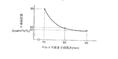
- FIG. 11 is a diagram showing the results of experiments with the apparatus of the present embodiment regarding the relationship between the height from the cold air jet nozzle 70 to the lower surface of the belt and the heat transfer coefficient to the metal belt.
- the upper surface 68b of the box-like casing 68 is inclined, and the distance from the cold air outlet 70 to the lower surface of the belt changes in the range of 75 to 95 mm.
- the heat transfer coefficient with respect to the belt does not change much even if the distance between the cold air jet 70 and the lower surface of the belt changes. Therefore, it is understood that the cooling effect of the conveyor belt 32 is hardly reduced even if the upper surface 68 b is inclined as in the present embodiment.
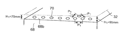
- FIG. 12A shows a box-shaped casing 68 of the present embodiment.
- Upper surface 68b of the box-shaped casing 68 since the inclined in the width direction of the conveyor belt 32, the interval H 1 from the cold air ejection port 70 to the conveyor belt 32 varies between 75 ⁇ 95 mm.
- the diameter of the circular cold air jets 70 is 25 mm ⁇ , and the cold air jets 70 are arranged to form an equilateral triangle.
- Pitch P 1 between the cold air ejection port 70 is 100 mm.
- FIG. 12B is a configuration shown as a comparative example.
- 'Multiple exhaust space e is provided in a box-shaped casing 68' box-shaped casing 68 intervals of H 2 flat ejection surface 68b 'and the conveyor belt 32 is 50 mm, a constant in the width direction of the conveyor belt 32 is there.
- the flat injection surface 68b ' is provided with a circular cold air outlet 70' having a diameter of 12.5 mm ⁇ .
- Each cold air ejection port 70 ' is arranged to form an equilateral triangle with one another, each cold air ejection port 70' the pitch P 2 between is 50 mm.
- the aperture ratio of the flat injection surface 68b and the flat injection surface 68b ' is set to be the same.
- the curve X is the case where the box-like casing 68 is used
- the curve Y is the case where the box-like casing 68 'is used.
- the curve Z is the temperature transition of the cooling space
- the curve W is the transition of the outside air temperature. The temperature of konnyaku was measured by a temperature sensor pierced at the center of konnyaku.
- the maintenance space 46 in which the operator can enter from the open / close door 20 is provided, maintenance in the housing 12 is facilitated. Furthermore, since the open / close door 20 is provided in the maintenance space 46 under normal pressure, it is not dangerous even if the open / close door 20 is opened during operation of the apparatus. Furthermore, since the axial flow fan 52 is provided to form a cold air circulation flow, the number of installation can be reduced and power consumption can be reduced by about 30% as compared with a sirocco fan or the like.
- the present invention it is possible to realize a freezer device that can be compacted and can be accommodated in a container without disassembling, and the time required for transportation can be significantly reduced.
Landscapes
- Engineering & Computer Science (AREA)
- Chemical & Material Sciences (AREA)
- Combustion & Propulsion (AREA)
- Physics & Mathematics (AREA)
- Mechanical Engineering (AREA)
- Thermal Sciences (AREA)
- General Engineering & Computer Science (AREA)
- Devices That Are Associated With Refrigeration Equipment (AREA)
Abstract
Description
また、空気冷却器の上方に送風機120を配置し、上から下に向う冷気流を形成しているため、該冷気流の整流化のため、大きな正圧空間を形成する必要がある。またコンベアベルトの上下に漏斗形断面を有するスリットノズルを備えた上部冷気噴射部114及び下部冷気噴射部116を配設しているため、これらの設置スペースを大きく取らざるを得なかった。
また、コンベアベルトの復路には、蛇行防止装置を設けているが、この蛇行防止装置が氷結して本来の機能を発揮できない場合があった。
断熱壁で囲まれた横長の冷却空間を形成するハウジングと、該冷却空間の長手方向に配設された被冷却物搬送用コンベアベルトと、該冷却空間に冷気循環流を形成する空気冷却器及び送風機からなる冷気循環装置とを備え、該被冷却物に対し冷却又は冷凍の連続処理を可能にしたフリーザー装置において、
前記ハウジングが矩形の横断面を有し、該横断面の上部領域に設けられ、前記空気冷却器と送風機とが隣接配置されて負圧空間を形成する負圧室と、
該負圧室の下方領域に設けられ、前記送風機から冷気が供給されて正圧空間を形成し、前記コンベアベルトと該コンベアベルトに向けて上下方向から冷気を噴射する冷気噴出部とが設けられた正圧室と、
該負圧室及び正圧室の側方領域に設けられ、該正圧室で被冷却物の冷却に供された後の冷気を受け入れ、受け入れた冷気を該負圧室に戻す冷気の戻り流を形成する常圧のメンテナンス空間と、を備えているものである。
これによって、ハウジングの幅寸法を拡大することなく、正圧室内の冷気噴出部に冷気を供給する冷気流路を確保できる。さらに、下部正圧室内で冷気の滑らかな循環流を形成でき、冷気循環流の圧損を低減できるので、送風機の動力を低減できる。
また、冷却に供した後の冷気をメンテナンス空間を経由して負圧室に戻すようにしたので、冷気の滑らかな循環流を形成でき、冷気循環流の圧損を低減して、送風機の動力を低減できる。
一方、ハウジング12内では、空気冷却器48及び軸流ファン52が稼動しており、空気冷却器48で冷却された冷気cは、軸流ファン52により、通風路38aを通って正圧室44に送られる。
なお、図16に、比較例として、矩形ノズル部152を有し、先端平坦噴射面154に穿孔を設けてなる上部冷気噴射部150で構成した上部冷気噴射部を示す。
この構成では、矩形ノズル部152の高さh及び矩形ノズル部152間のピッチpを相当大きく取らないと、排気空間eを十分確保することができない。
また、通風路38aの下方に、箱状ケーシング66内に冷気cを導く冷気通路を上下方向に形成したので、前方壁12aに冷気流路のための出っ張りを設ける必要がない。
さらに、従動ドラム34、駆動ドラム36及び金属ベルト32の復路32bをハウジング12外に配置しているので、その分コンベアベルト32の設置高さを低減できる。そのため、図10に示すように、分解することなく前記寸法のコンテナ90に収容できる。
さらに、冷気循環流を形成するため軸流ファン52を設けているので、シロッコファン等と比べて、設置数を低減できると共に、消費電力を約30%節減できる。
Claims (5)
- 断熱壁で囲まれた横長の冷却空間を形成するハウジングと、該冷却空間の長手方向に配設された被冷却物搬送用コンベアベルトと、該冷却空間に冷気循環流を形成する空気冷却器及び送風機からなる冷気循環装置とを備え、該被冷却物に対し冷却又は冷凍の連続処理を可能にしたフリーザー装置において、
前記ハウジングが矩形の横断面を有し、該横断面の上部領域に設けられ、前記空気冷却器と送風機とが隣接配置されて負圧空間を形成する負圧室と、
該負圧室の下方領域に設けられ、前記送風機から冷気が供給されて正圧空間を形成し、前記コンベアベルトと該コンベアベルトに向けて上下方向から冷気を噴射する冷気噴出部とが設けられた正圧室と、
該負圧室及び正圧室の側方領域に設けられ、該正圧室で被冷却物の冷却に供された後の冷気を受け入れ、受け入れた冷気を該負圧室に戻す冷気の戻り流を形成する常圧のメンテナンス空間と、を備えていることを特徴とするフリーザー装置。 - 前記負圧室から正圧室に冷気を供給する冷気口が前記メンテナンス空間と離れた側のハウジング側壁近傍にもうけられ、該冷気口の下方に上下方向に前記下部冷気噴射部に冷気を供給する送気空間が形成されていることを特徴とする請求項1に記載のフリーザー装置。
- 前記メンテナンス空間に面したハウジング側壁に開閉扉を設け、該メンテナンス空間にオペレータが立ち入り可能にしたことを特徴とする請求項1に記載のフリーザー装置。
- 前記コンベアベルトが、前記正圧室内に配設され両端部が前記冷却空間の外部に導設された往路と、両端が該往路と連結され冷却空間の外側下方に配設された復路とからなるエンドレスベルトであり、
冷却空間の外部に回転ドラムを設け、コンベアベルトを回転ドラムの外周面に巻回させてコンベアベルトを支持搬送するように構成したことを特徴とする請求項1又は2に記載のフリーザー装置。 - 前記コンベアベルトのベルト体が冷気抜け孔のない金属ベルトで構成されていることを特徴とする請求項1~4のいずれか1項に記載のフリーザー装置。
Priority Applications (4)
| Application Number | Priority Date | Filing Date | Title |
|---|---|---|---|
| JP2010542459A JP5486511B2 (ja) | 2010-06-30 | 2010-06-30 | フリーザー装置 |
| KR1020127009290A KR101693617B1 (ko) | 2010-06-30 | 2010-06-30 | 프리저 장치 |
| PCT/JP2010/061212 WO2012001797A1 (ja) | 2010-06-30 | 2010-06-30 | フリーザー装置 |
| TW099142437A TWI579515B (zh) | 2010-06-30 | 2010-12-06 | Cooling device |
Applications Claiming Priority (1)
| Application Number | Priority Date | Filing Date | Title |
|---|---|---|---|
| PCT/JP2010/061212 WO2012001797A1 (ja) | 2010-06-30 | 2010-06-30 | フリーザー装置 |
Publications (1)
| Publication Number | Publication Date |
|---|---|
| WO2012001797A1 true WO2012001797A1 (ja) | 2012-01-05 |
Family
ID=45401552
Family Applications (1)
| Application Number | Title | Priority Date | Filing Date |
|---|---|---|---|
| PCT/JP2010/061212 Ceased WO2012001797A1 (ja) | 2010-06-30 | 2010-06-30 | フリーザー装置 |
Country Status (4)
| Country | Link |
|---|---|
| JP (1) | JP5486511B2 (ja) |
| KR (1) | KR101693617B1 (ja) |
| TW (1) | TWI579515B (ja) |
| WO (1) | WO2012001797A1 (ja) |
Cited By (3)
| Publication number | Priority date | Publication date | Assignee | Title |
|---|---|---|---|---|
| EP2957846A1 (en) * | 2014-06-13 | 2015-12-23 | Officine Smac S.P.A. | Apparatus for cooling ceramic products |
| CN108088149A (zh) * | 2017-12-12 | 2018-05-29 | 梁林燕 | 一种方便物体取放的速冻机 |
| JP2020504001A (ja) * | 2017-12-01 | 2020-02-06 | 上海海洋大学Shanghai Ocean University | 長円形漏斗状の噴射ノズル構造 |
Families Citing this family (2)
| Publication number | Priority date | Publication date | Assignee | Title |
|---|---|---|---|---|
| CN106123483B (zh) * | 2016-06-22 | 2019-01-25 | 山东科技大学 | 一种具有双重冷冻功效的血浆速冻柜 |
| KR102900925B1 (ko) | 2023-02-02 | 2025-12-17 | 박선규 | 다단 방식 프리저 |
Citations (5)
| Publication number | Priority date | Publication date | Assignee | Title |
|---|---|---|---|---|
| JP2002039662A (ja) * | 2000-07-27 | 2002-02-06 | Kenji Aoi | トンネル式冷却冷凍装置 |
| JP2004028536A (ja) * | 2002-06-28 | 2004-01-29 | Takahashi Kogyo Kk | 凍結装置 |
| WO2006046317A1 (ja) * | 2004-10-29 | 2006-05-04 | Mayekawa Mfg. Co., Ltd. | 連続搬送式フリーザ |
| JP2007024364A (ja) * | 2005-07-14 | 2007-02-01 | Takahashi Kogyo Kk | 連続式急速凍結装置 |
| JP2009121715A (ja) * | 2007-11-13 | 2009-06-04 | Toyo Eng Works Ltd | 連続急速冷却凍結装置 |
Family Cites Families (4)
| Publication number | Priority date | Publication date | Assignee | Title |
|---|---|---|---|---|
| JPS5960166A (ja) * | 1982-09-27 | 1984-04-06 | 三菱電機株式会社 | 凍結装置 |
| JPS63259366A (ja) * | 1987-04-14 | 1988-10-26 | 株式会社 前川製作所 | ジエツト気流による冷凍、加熱または乾燥等の伝熱促進方法 |
| JP3656851B2 (ja) * | 2003-11-04 | 2005-06-08 | 株式会社前川製作所 | 食品の凍結方法と装置 |
| JP4318699B2 (ja) * | 2006-06-21 | 2009-08-26 | 株式会社前川製作所 | 食肉の搬送式凍結方法及び装置 |
-
2010
- 2010-06-30 WO PCT/JP2010/061212 patent/WO2012001797A1/ja not_active Ceased
- 2010-06-30 KR KR1020127009290A patent/KR101693617B1/ko not_active Expired - Fee Related
- 2010-06-30 JP JP2010542459A patent/JP5486511B2/ja active Active
- 2010-12-06 TW TW099142437A patent/TWI579515B/zh not_active IP Right Cessation
Patent Citations (5)
| Publication number | Priority date | Publication date | Assignee | Title |
|---|---|---|---|---|
| JP2002039662A (ja) * | 2000-07-27 | 2002-02-06 | Kenji Aoi | トンネル式冷却冷凍装置 |
| JP2004028536A (ja) * | 2002-06-28 | 2004-01-29 | Takahashi Kogyo Kk | 凍結装置 |
| WO2006046317A1 (ja) * | 2004-10-29 | 2006-05-04 | Mayekawa Mfg. Co., Ltd. | 連続搬送式フリーザ |
| JP2007024364A (ja) * | 2005-07-14 | 2007-02-01 | Takahashi Kogyo Kk | 連続式急速凍結装置 |
| JP2009121715A (ja) * | 2007-11-13 | 2009-06-04 | Toyo Eng Works Ltd | 連続急速冷却凍結装置 |
Cited By (3)
| Publication number | Priority date | Publication date | Assignee | Title |
|---|---|---|---|---|
| EP2957846A1 (en) * | 2014-06-13 | 2015-12-23 | Officine Smac S.P.A. | Apparatus for cooling ceramic products |
| JP2020504001A (ja) * | 2017-12-01 | 2020-02-06 | 上海海洋大学Shanghai Ocean University | 長円形漏斗状の噴射ノズル構造 |
| CN108088149A (zh) * | 2017-12-12 | 2018-05-29 | 梁林燕 | 一种方便物体取放的速冻机 |
Also Published As
| Publication number | Publication date |
|---|---|
| JP5486511B2 (ja) | 2014-05-07 |
| TW201200826A (en) | 2012-01-01 |
| KR20130098846A (ko) | 2013-09-05 |
| JPWO2012001797A1 (ja) | 2013-08-22 |
| KR101693617B1 (ko) | 2017-01-06 |
| TWI579515B (zh) | 2017-04-21 |
Similar Documents
| Publication | Publication Date | Title |
|---|---|---|
| KR101693634B1 (ko) | 냉기 분사 기구 | |
| JP3366977B2 (ja) | 冷却装置及びその冷却方法 | |
| CN100363695C (zh) | 气流增强的隧道式冷冻设备 | |
| WO2012001797A1 (ja) | フリーザー装置 | |
| US20220104522A1 (en) | Apparatus and method for chilling or freezing | |
| US20100319365A1 (en) | Cross flow tunnel freezer system | |
| JP5600395B2 (ja) | 食品の搬送式冷却方法及び装置 | |
| JP2001120243A (ja) | 食品の連続式急速凍結装置 | |
| JP4786726B2 (ja) | コンベア式冷凍装置 | |
| US20140000296A1 (en) | Mechanically refrigerated spiral freezer and method of using same to chill or freeze products | |
| JP4493688B2 (ja) | 連続急速冷却凍結装置 | |
| US20130167562A1 (en) | Cryogenic spiral freezer | |
| JP4524305B2 (ja) | 連続急速冷却凍結装置 | |
| EP1251752B1 (en) | Continuous flow freezing plant, in particular for edible ice products | |
| JP2000220940A (ja) | トンネル式冷却冷凍装置 | |
| JP4493687B2 (ja) | 連続急速冷却凍結装置 | |
| JP2025087314A (ja) | フリーザ | |
| JP2025087317A (ja) | フリーザ | |
| US20130167561A1 (en) | Method of chilling or freezing products in a cryogenic spiral freezer | |
| KR950027325A (ko) | 냉동저장, 가열판매식 자동판매기의 냉기순환 및 냉기유도장치 | |
| TH52368B (th) | เครื่องมือช่องแช่แข็ง | |
| TH124046A (th) | เครื่องมือช่องแช่แข็ง |
Legal Events
| Date | Code | Title | Description |
|---|---|---|---|
| WWE | Wipo information: entry into national phase |
Ref document number: 2010542459 Country of ref document: JP |
|
| 121 | Ep: the epo has been informed by wipo that ep was designated in this application |
Ref document number: 10854094 Country of ref document: EP Kind code of ref document: A1 |
|
| ENP | Entry into the national phase |
Ref document number: 20127009290 Country of ref document: KR Kind code of ref document: A |
|
| WWE | Wipo information: entry into national phase |
Ref document number: 1201002334 Country of ref document: TH |
|
| NENP | Non-entry into the national phase |
Ref country code: DE |
|
| 122 | Ep: pct application non-entry in european phase |
Ref document number: 10854094 Country of ref document: EP Kind code of ref document: A1 |