WO2011162289A1 - 移動通信方法及びリレーノード - Google Patents
移動通信方法及びリレーノード Download PDFInfo
- Publication number
- WO2011162289A1 WO2011162289A1 PCT/JP2011/064250 JP2011064250W WO2011162289A1 WO 2011162289 A1 WO2011162289 A1 WO 2011162289A1 JP 2011064250 W JP2011064250 W JP 2011064250W WO 2011162289 A1 WO2011162289 A1 WO 2011162289A1
- Authority
- WO
- WIPO (PCT)
- Prior art keywords
- relay node
- rrc
- release message
- connection release
- base station
- Prior art date
- Legal status (The legal status is an assumption and is not a legal conclusion. Google has not performed a legal analysis and makes no representation as to the accuracy of the status listed.)
- Ceased
Links
Images


Classifications
-
- H—ELECTRICITY
- H04—ELECTRIC COMMUNICATION TECHNIQUE
- H04W—WIRELESS COMMUNICATION NETWORKS
- H04W88/00—Devices specially adapted for wireless communication networks, e.g. terminals, base stations or access point devices
- H04W88/02—Terminal devices
- H04W88/04—Terminal devices adapted for relaying to or from another terminal or user
-
- H—ELECTRICITY
- H04—ELECTRIC COMMUNICATION TECHNIQUE
- H04B—TRANSMISSION
- H04B7/00—Radio transmission systems, i.e. using radiation field
- H04B7/14—Relay systems
- H04B7/15—Active relay systems
- H04B7/155—Ground-based stations
-
- H—ELECTRICITY
- H04—ELECTRIC COMMUNICATION TECHNIQUE
- H04W—WIRELESS COMMUNICATION NETWORKS
- H04W76/00—Connection management
- H04W76/30—Connection release
-
- H—ELECTRICITY
- H04—ELECTRIC COMMUNICATION TECHNIQUE
- H04W—WIRELESS COMMUNICATION NETWORKS
- H04W84/00—Network topologies
- H04W84/02—Hierarchically pre-organised networks, e.g. paging networks, cellular networks, WLAN [Wireless Local Area Network] or WLL [Wireless Local Loop]
- H04W84/04—Large scale networks; Deep hierarchical networks
- H04W84/042—Public Land Mobile systems, e.g. cellular systems
- H04W84/047—Public Land Mobile systems, e.g. cellular systems using dedicated repeater stations
Definitions
- the present invention relates to a mobile communication method and a relay node.
- a relay node RN (Relay Node) that can be connected to the radio base station DeNB (Doner eNB) via the Un interface can be used.
- 3GPP TR36.806 (V9.0.0), “Evolved Universal Terrestrial Radio Access (E-UTRA); Relay architectures for E-UTRA (LTE-Advanced), March, 2010” (Release 10 months) 3GPP TS36.413 (V9.3.0), “Evolved Universal Terrestrial Radio Access Network (E-UTRAN); S1 application protocol (S1AP)”, June 2010 3GPP TS36.331 (V9.3.0), “Radio Resource Control (RRC); Protocol specification”, June 2010
- the relay node RN is configured to be able to transition between the “RRC_IDLE state” and the “RRC_CONNECTED state” under the radio base station DeNB.
- the mobile station UE is configured to be able to transition between the “RRC_IDLE state” and the “RRC_CONNECTED state” under the relay node RN.
- An object of the present invention is to provide a mobile communication method and a relay node capable of causing a mobile station UE under the RN to be in the “RRC_CONNECTED state” to transition to the “RRC_IDLE state”.
- a first feature of the present invention is a mobile communication method, in which a radio base station transmits a first connection release message to a relay node in a connected state under the radio base station, and When the relay node receives the first connection release message, a step B of transmitting a second connection release message to the mobile station in the connected state under the relay node; and When receiving a connection release message, the process C includes a process C for transitioning to an idle state, and a process D for transitioning to an idle state after a predetermined period of time has elapsed since the relay node transmitted the second connection release message. This is the gist.
- the relay node when the relay node is in a connected state under the control of a radio base station, and when the first connection release message is received from the radio base station, the relay node A mobile station configured to transmit a second connection release message to a mobile station in a connected state under a node; and after a predetermined period has elapsed since the second connection release message was transmitted, And a control unit configured to cause the relay node to transition to an idle state.
- the relay node RN in the “RRC_CONNECTED state” under the radio base station DeNB transitions to the “RRC_IDLE state”
- the mobile communication method and the relay node capable of causing the mobile station UE in “” to transition to the “RRC_IDLE state” can be provided.
- FIG. 1 is an overall configuration diagram of a mobile communication system according to a first embodiment of the present invention.
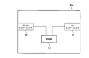
- FIG. 2 is a functional block diagram of the relay node according to the first embodiment of the present invention.
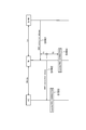
- FIG. 3 is a sequence diagram showing operations of the mobile communication system according to the first embodiment of the present invention.
- FIG. 4 is a flowchart showing the operation of the relay node according to the first embodiment of the present invention.
- Mobile communication system according to the first embodiment of the present invention A mobile communication system according to a first embodiment of the present invention will be described with reference to FIGS.
- the mobile communication system is an LTE-Advanced mobile communication system, and includes a radio base station DeNB and a relay node RN as shown in FIG.
- the relay node RN includes an Un interface 11, an RN-Uu interface 12, and a control unit 13.
- the Un interface 11 is configured to serve as an interface with the radio base station DeNB.
- the RN-Uu interface 12 is configured to serve as an interface with the mobile station UE.
- the control unit 13 is configured to control transmission / reception of signals to / from the radio base station DeNB via the Un interface 11 and transmission / reception of signals to / from the mobile station UE via the RN-Uu interface 12. ing.
- control unit 13 is configured to transition the relay node RN between the “RRC_IDLE state” and the “RRC_CONNECTED state” under the radio base station DeNB.
- the control unit 13 performs the RN ⁇
- the Uu interface 12 is instructed to transmit a “RRC connection release message” to the mobile station UE in the “RRC_CONNECTED state” under the relay node RN, and the “RNC connection release message” is transmitted by the RN-Uu interface 12.
- the relay node RN is configured to transition to the “RRC_IDLE state” after a predetermined period of time has elapsed since the transmission.
- the control unit 13 starts a predetermined timer, and transitions the relay node RN to the “RRC_IDLE state” when the predetermined timer expires. You may be comprised so that it may make.
- step S1001 the radio base station DeNB transmits a “RRC connection release message” to the relay node RN that is in the “RRC_CONNECTED state” under the radio base station DeNB.
- the relay node RN After the time T1 has elapsed since receiving the “RRC connection release message”, the relay node RN performs “RRC connection” to the mobile station UE in the “RRC_CONNECTED state” under the relay node RN in step S1002. “release message” is transmitted.
- the time T1 may be the shortest time at which the relay node RN can transmit the signal received via the Un interface 11 via the RN-Uu interface 12.
- step S1003 when the mobile station UE receives the “RRC connection release message”, the mobile station UE changes to the “RRC_IDLE state” by executing the “Leaving RRC_CONNECTED procedure”.
- the relay node RN transitions to the “RRC_IDLE state” by executing the “Leaving RRC_CONNECTED procedure” after the time T2 has elapsed after transmitting the “RRC connection release message”.
- the time T2 may be a time from when a predetermined timer starts until it expires.
- the relay node RN in the “RRC_CONNECTED state” under the radio base station DeNB receives the “RRC connection release message” from the radio base station DeNB in step S101, the relay node RN in step S102. It is determined whether or not there is a mobile station UE that is under the “RRC_CONNECTED state”.
- step S103 If “YES”, the operation proceeds to step S103, and if “NO”, the operation proceeds to step S104.
- step S103 the relay node RN receives the “RRC connection release message”, and after the time T1 has elapsed, the relay node RN sends an “RRC connection release message” to the mobile station UE in the “RRC_CONNECTED state” under the relay node RN. ".
- step S104 the relay node RN transits to the “RRC_IDLE state” by executing the “Leaving RRC_CONNECTED procedure” after the time T2 has elapsed since the “RRC connection release message” has been transmitted.
- step S104 the relay node RN executes the “Leaving RRC_CONNECTED procedure” after the time T1 has elapsed since the “RRC connection release message” was transmitted. May change to the “RRC_IDLE state”.
- the relay node RN that is in the “RRC_CONNECTED state” under the radio base station DeNB receives the “RRC connection release message” from the radio base station DeNB, immediately stops transmission on the RN-Uu interface, Since the mobile station UE in the “RRC_CONNECTED state” under the relay node RN detects RLF (Radio Link Failure), there is a possibility that it takes time to shift to the “RRC_IDLE state”.
- RLF Radio Link Failure
- the relay node RN in the “RRC_CONNECTED state” under the radio base station DeNB receives the “RRC connection release message” from the radio base station DeNB
- the mobile station UE in the “RRC_CONNECTED state” under the node RN is configured to transition to the “RRC_IDLE state” and then to the “RRC_IDLE state”.
- the mobile communication system it is possible to reduce the time until the mobile station UE in the “RRC_CONNECTED state” under the relay node RN transitions to the “RRC_IDLE state”.
- the first feature of the present embodiment is a mobile communication method, in which a radio base station DeNB is connected to a relay node RN that is in the “RRC_CONNECTED state (connection state)” under the radio base station DeNB, with “RRC connection release”.
- the relay node RN receives the “RRC connection release message” and the mobile station UE in the “RRC_CONNECTED state” under the relay node RN, the process A that transmits the message (first connection release message) ”and the relay node RN receives the“ RRC connection release message ”.
- the process B that transmits the “RRC connection release message (second connection release message)” and the mobile station UE receives the “RRC connection release message”
- the “RR” is displayed.
- step B the relay node RN activates a predetermined timer when the “RRC connection release message” is transmitted.
- the relay node RN expires the predetermined timer. In this case, the state may transit to the “RRC_IDLE state”.
- the second feature of the present embodiment is a relay node RN, in which the relay node RN is in the “RRC_CONNECTED state” under the control of the radio base station DeNB, and the “RRC connection release message” is sent from the radio base station DeNB.
- the RN-Uu interface 12 transmission unit
- the RN-Uu interface 12 configured to transmit the “RRC connection release message” to the mobile station UE in the “RRC_CONNECTED state” under the relay node RN
- “RRC” and a control unit 13 configured to transition the relay node RN to the “RRC_IDLE state” after a predetermined time T2 has elapsed since the transmission of the “connection release message”.
- control unit 13 activates a predetermined timer when the “RRC connection release message” is transmitted, and sets the relay node RN to the “RRC_IDLE state” when the predetermined timer expires. You may be comprised so that it may change to.
- the operations of the radio base station DeNB, the relay node RN, and the mobile station UE described above may be performed by hardware, may be performed by a software module executed by a processor, or may be performed by a combination of both. May be.
- Software modules include RAM (Random Access Memory), flash memory, ROM (Read Only Memory), EPROM (Erasable Programmable ROM), EEPROM (Electronically Erasable and Programmable, Removable ROM, and Hard Disk). Alternatively, it may be provided in a storage medium of an arbitrary format such as a CD-ROM.
- Such a storage medium is connected to the processor so that the processor can read and write information from and to the storage medium. Further, such a storage medium may be integrated in the processor. Such a storage medium and processor may be provided in the ASIC. Such an ASIC may be provided in the radio base station DeNB, the relay node RN, or the mobile station UE. Further, the storage medium and the processor may be provided in the radio base station DeNB, the relay node RN, and the mobile station UE as discrete components.
Landscapes
- Engineering & Computer Science (AREA)
- Computer Networks & Wireless Communication (AREA)
- Signal Processing (AREA)
- Mobile Radio Communication Systems (AREA)
Abstract
Description
図1乃至図4を参照して、本発明の第1の実施形態に係る移動通信システムについて説明する。
11…Unインターフェイス
12…RN-Uuインターフェイス
13…制御部
Claims (4)
- 無線基地局が、該無線基地局配下で接続状態にあるリレーノードに対して、第1コネクション解放メッセージを送信する工程Aと、
前記リレーノードが、前記第1コネクション解放メッセージを受信した場合、該リレーノード配下で接続状態にある移動局に対して、第2コネクション解放メッセージを送信する工程Bと、
前記移動局が、前記第2コネクション解放メッセージを受信した場合、アイドル状態に遷移する工程Cと、
前記リレーノードが、前記第2コネクション解放メッセージを送信してから所定期間が経過した後に、アイドル状態に遷移する工程Dとを有することを特徴とする移動通信方法。 - 前記工程Bにおいて、前記リレーノードは、第2コネクション解放メッセージを送信した場合に、所定タイマを起動し、
前記工程Dにおいて、前記リレーノードは、前記所定タイマが満了した場合に、アイドル状態に遷移することを特徴とする請求項1に記載の移動通信方法。 - リレーノードであって、
前記リレーノードが無線基地局配下で接続状態にある場合で、かつ、該無線基地局から第1コネクション解放メッセージを受信した場合、該リレーノード配下で接続状態にある移動局に対して、第2コネクション解放メッセージを送信するように構成されている送信部と、
前記第2コネクション解放メッセージが送信されてから所定期間が経過した後に、前記リレーノードをアイドル状態に遷移させるように構成されている制御部とを具備することを特徴とするリレーノード。 - 前記制御部は、前記第2コネクション解放メッセージが送信された場合に、所定タイマを起動し、該所定タイマが満了した場合に、前記リレーノードをアイドル状態に遷移させるように構成されていることを特徴とする請求項3に記載のリレーノード。
Priority Applications (2)
| Application Number | Priority Date | Filing Date | Title |
|---|---|---|---|
| CN201180031136.3A CN102972087B (zh) | 2010-06-24 | 2011-06-22 | 移动通信方法以及中继节点 |
| US13/805,680 US8874100B2 (en) | 2010-06-24 | 2011-06-22 | Mobile communication method and relay node |
Applications Claiming Priority (2)
| Application Number | Priority Date | Filing Date | Title |
|---|---|---|---|
| JP2010144318A JP5277210B2 (ja) | 2010-06-24 | 2010-06-24 | 移動通信方法及びリレーノード |
| JP2010-144318 | 2010-06-24 |
Publications (1)
| Publication Number | Publication Date |
|---|---|
| WO2011162289A1 true WO2011162289A1 (ja) | 2011-12-29 |
Family
ID=45371466
Family Applications (1)
| Application Number | Title | Priority Date | Filing Date |
|---|---|---|---|
| PCT/JP2011/064250 Ceased WO2011162289A1 (ja) | 2010-06-24 | 2011-06-22 | 移動通信方法及びリレーノード |
Country Status (4)
| Country | Link |
|---|---|
| US (1) | US8874100B2 (ja) |
| JP (1) | JP5277210B2 (ja) |
| CN (1) | CN102972087B (ja) |
| WO (1) | WO2011162289A1 (ja) |
Families Citing this family (14)
| Publication number | Priority date | Publication date | Assignee | Title |
|---|---|---|---|---|
| JP5633568B2 (ja) * | 2010-09-17 | 2014-12-03 | 富士通株式会社 | 無線通信システム、リレー局、端末及び無線通信方法 |
| WO2014029429A1 (en) * | 2012-08-22 | 2014-02-27 | Nokia Siemens Networks Oy | Handling radio link failure |
| US9445343B2 (en) * | 2013-07-09 | 2016-09-13 | Alcatel Lucent | Systems for switching modes in wireless sessions |
| KR101715316B1 (ko) * | 2013-09-16 | 2017-03-10 | 이노베이티브 소닉 코포레이션 | Wlan3gpp 인터워킹의 시그널링을 적용하는 방법 및 장치 |
| CN107852765B (zh) * | 2015-07-29 | 2022-03-08 | 夏普株式会社 | 用于设备到设备中继过程的方法 |
| WO2017108487A1 (en) | 2015-12-21 | 2017-06-29 | Sony Corporation | Telecommunications apparatus and methods |
| CN105517191B (zh) * | 2016-01-07 | 2019-04-12 | 宇龙计算机通信科技(深圳)有限公司 | D2d中继通信中的连接管理方法及装置、终端和基站 |
| KR102290689B1 (ko) * | 2016-08-23 | 2021-08-17 | 후아웨이 테크놀러지 컴퍼니 리미티드 | 단말의 이동성 패턴을 관리하는 방법 및 장치 |
| WO2018195787A1 (en) | 2017-04-26 | 2018-11-01 | Qualcomm Incorporated | Enhanced machine type communications quick idle transition after connection release |
| KR20230043102A (ko) * | 2020-07-25 | 2023-03-30 | 퀄컴 인코포레이티드 | 사이드링크 레이어 2 릴레이 시스템에서의 상태 천이 |
| EP4195866A4 (en) * | 2020-08-05 | 2024-08-28 | Mitsubishi Electric Corporation | Communication system and communication terminal |
| CN114158113B (zh) * | 2020-09-08 | 2023-11-21 | 维沃移动通信有限公司 | 工作状态的切换方法及装置、终端及可读存储介质 |
| CN114615758A (zh) * | 2020-12-04 | 2022-06-10 | 大唐移动通信设备有限公司 | 终端设备无线资源控制rrc状态管理方法及其装置 |
| CN116349402A (zh) * | 2021-02-05 | 2023-06-27 | Oppo广东移动通信有限公司 | 状态转换方法、装置、设备及存储介质 |
Family Cites Families (11)
| Publication number | Priority date | Publication date | Assignee | Title |
|---|---|---|---|---|
| US5812528A (en) * | 1995-11-17 | 1998-09-22 | Telecommunications Techniques Corporation | Measuring round trip time in ATM network virtual connections |
| US6069947A (en) * | 1997-12-16 | 2000-05-30 | Nortel Networks Corporation | Communication system architecture and operating protocol therefor |
| US6167028A (en) * | 1998-06-01 | 2000-12-26 | Motorola, Inc. | Methods and apparatus for facilitating transmission of cells having multiple priorities in a cell relay network |
| US7496100B2 (en) * | 2000-04-18 | 2009-02-24 | Nippon Telegraph & Telephone Corporation | Method and apparatus for synchronous frame communication |
| US20070025342A1 (en) * | 2005-07-14 | 2007-02-01 | Gemini Mobile Technology, Inc. | Protocol optimization for wireless networks |
| KR100998924B1 (ko) * | 2007-07-24 | 2010-12-09 | 삼성전자주식회사 | 중계방식을 사용하는 무선통신시스템에서 전력을 제어하기위한 장치 및 방법 |
| US8855138B2 (en) * | 2008-08-25 | 2014-10-07 | Qualcomm Incorporated | Relay architecture framework |
| US8902805B2 (en) * | 2008-10-24 | 2014-12-02 | Qualcomm Incorporated | Cell relay packet routing |
| WO2010148344A1 (en) * | 2009-06-19 | 2010-12-23 | Research In Motion Limited | Mobile station association procedures with type ii relays |
| US20110051655A1 (en) * | 2009-08-25 | 2011-03-03 | Futurewei Technologies, Inc. | Relay System and Method in a Wireless Communications system |
| JP2012004638A (ja) * | 2010-06-14 | 2012-01-05 | Canon Inc | 電子機器、その制御方法、及び制御プログラム、並びに記録媒体 |
-
2010
- 2010-06-24 JP JP2010144318A patent/JP5277210B2/ja not_active Expired - Fee Related
-
2011
- 2011-06-22 US US13/805,680 patent/US8874100B2/en not_active Expired - Fee Related
- 2011-06-22 CN CN201180031136.3A patent/CN102972087B/zh not_active Expired - Fee Related
- 2011-06-22 WO PCT/JP2011/064250 patent/WO2011162289A1/ja not_active Ceased
Non-Patent Citations (2)
| Title |
|---|
| "Control Plane for Un interface", 3GPP TSG-RAN WG2 MEETING #68BIS R2-100176, 18 January 2010 (2010-01-18) * |
| "Details on the RRC Connection Release procedure", 3GPP TSG-RAN WG2 #60BIS TDOC R2-080250, 14 January 2008 (2008-01-14) * |
Also Published As
| Publication number | Publication date |
|---|---|
| CN102972087B (zh) | 2016-03-16 |
| CN102972087A (zh) | 2013-03-13 |
| US20130122892A1 (en) | 2013-05-16 |
| US8874100B2 (en) | 2014-10-28 |
| JP2012010112A (ja) | 2012-01-12 |
| JP5277210B2 (ja) | 2013-08-28 |
Similar Documents
| Publication | Publication Date | Title |
|---|---|---|
| JP5277210B2 (ja) | 移動通信方法及びリレーノード | |
| JP5187909B2 (ja) | 移動通信方法及びリレーノード | |
| US9832768B2 (en) | Mobile communication method and radio base station | |
| CN103168484B (zh) | 移动通信系统中的基站、中继台以及方法 | |
| JP4990386B2 (ja) | 移動通信方法、無線基地局及びリレーノード | |
| US9794778B2 (en) | Mobile communication method and mobile station to prohibit retransmission of assistance information | |
| CN103563425B (zh) | 移动通信方法、中继节点以及无线基站 | |
| WO2012008382A1 (ja) | 移動通信方法及びリレーノード | |
| JP5285659B2 (ja) | 移動通信方法及びリレーノード | |
| JP4814383B2 (ja) | 移動通信方法及びリレーノード | |
| JP4749480B2 (ja) | 移動通信方法、無線基地局及びリレーノード | |
| JP2012009963A (ja) | 移動通信方法及びリレーノード | |
| JP6450514B2 (ja) | 移動通信方法及び無線基地局 | |
| JP2011004375A (ja) | 移動通信方法、無線基地局及びリレーノード | |
| WO2012008412A1 (ja) | 移動通信方法、リレーノード及び無線基地局 | |
| JP2011238978A (ja) | 移動通信方法、リレーノード及び無線基地局 | |
| JP2011223122A (ja) | 移動通信方法及びリレーノード | |
| WO2012023456A1 (ja) | 移動通信システムにおける基地局、中継局及び方法 |
Legal Events
| Date | Code | Title | Description |
|---|---|---|---|
| WWE | Wipo information: entry into national phase |
Ref document number: 201180031136.3 Country of ref document: CN |
|
| 121 | Ep: the epo has been informed by wipo that ep was designated in this application |
Ref document number: 11798171 Country of ref document: EP Kind code of ref document: A1 |
|
| NENP | Non-entry into the national phase |
Ref country code: DE |
|
| WWE | Wipo information: entry into national phase |
Ref document number: 13805680 Country of ref document: US |
|
| 122 | Ep: pct application non-entry in european phase |
Ref document number: 11798171 Country of ref document: EP Kind code of ref document: A1 |