WO2011162099A1 - 内視鏡装置 - Google Patents
内視鏡装置 Download PDFInfo
- Publication number
- WO2011162099A1 WO2011162099A1 PCT/JP2011/063063 JP2011063063W WO2011162099A1 WO 2011162099 A1 WO2011162099 A1 WO 2011162099A1 JP 2011063063 W JP2011063063 W JP 2011063063W WO 2011162099 A1 WO2011162099 A1 WO 2011162099A1
- Authority
- WO
- WIPO (PCT)
- Prior art keywords
- signal
- color
- matrix
- unit
- intensity ratio
- Prior art date
Links
Images


Classifications
-
- A—HUMAN NECESSITIES
- A61—MEDICAL OR VETERINARY SCIENCE; HYGIENE
- A61B—DIAGNOSIS; SURGERY; IDENTIFICATION
- A61B1/00—Instruments for performing medical examinations of the interior of cavities or tubes of the body by visual or photographical inspection, e.g. endoscopes; Illuminating arrangements therefor
- A61B1/00002—Operational features of endoscopes
- A61B1/00004—Operational features of endoscopes characterised by electronic signal processing
- A61B1/00009—Operational features of endoscopes characterised by electronic signal processing of image signals during a use of endoscope
-
- A—HUMAN NECESSITIES
- A61—MEDICAL OR VETERINARY SCIENCE; HYGIENE
- A61B—DIAGNOSIS; SURGERY; IDENTIFICATION
- A61B1/00—Instruments for performing medical examinations of the interior of cavities or tubes of the body by visual or photographical inspection, e.g. endoscopes; Illuminating arrangements therefor
- A61B1/00002—Operational features of endoscopes
- A61B1/00059—Operational features of endoscopes provided with identification means for the endoscope
-
- A—HUMAN NECESSITIES
- A61—MEDICAL OR VETERINARY SCIENCE; HYGIENE
- A61B—DIAGNOSIS; SURGERY; IDENTIFICATION
- A61B1/00—Instruments for performing medical examinations of the interior of cavities or tubes of the body by visual or photographical inspection, e.g. endoscopes; Illuminating arrangements therefor
- A61B1/00163—Optical arrangements
- A61B1/00186—Optical arrangements with imaging filters
-
- A—HUMAN NECESSITIES
- A61—MEDICAL OR VETERINARY SCIENCE; HYGIENE
- A61B—DIAGNOSIS; SURGERY; IDENTIFICATION
- A61B1/00—Instruments for performing medical examinations of the interior of cavities or tubes of the body by visual or photographical inspection, e.g. endoscopes; Illuminating arrangements therefor
- A61B1/06—Instruments for performing medical examinations of the interior of cavities or tubes of the body by visual or photographical inspection, e.g. endoscopes; Illuminating arrangements therefor with illuminating arrangements
- A61B1/07—Instruments for performing medical examinations of the interior of cavities or tubes of the body by visual or photographical inspection, e.g. endoscopes; Illuminating arrangements therefor with illuminating arrangements using light-conductive means, e.g. optical fibres
-
- H—ELECTRICITY
- H04—ELECTRIC COMMUNICATION TECHNIQUE
- H04N—PICTORIAL COMMUNICATION, e.g. TELEVISION
- H04N23/00—Cameras or camera modules comprising electronic image sensors; Control thereof
- H04N23/50—Constructional details
- H04N23/555—Constructional details for picking-up images in sites, inaccessible due to their dimensions or hazardous conditions, e.g. endoscopes or borescopes
-
- H—ELECTRICITY
- H04—ELECTRIC COMMUNICATION TECHNIQUE
- H04N—PICTORIAL COMMUNICATION, e.g. TELEVISION
- H04N23/00—Cameras or camera modules comprising electronic image sensors; Control thereof
- H04N23/80—Camera processing pipelines; Components thereof
- H04N23/84—Camera processing pipelines; Components thereof for processing colour signals
-
- H—ELECTRICITY
- H04—ELECTRIC COMMUNICATION TECHNIQUE
- H04N—PICTORIAL COMMUNICATION, e.g. TELEVISION
- H04N25/00—Circuitry of solid-state image sensors [SSIS]; Control thereof
- H04N25/10—Circuitry of solid-state image sensors [SSIS]; Control thereof for transforming different wavelengths into image signals
- H04N25/11—Arrangement of colour filter arrays [CFA]; Filter mosaics
- H04N25/13—Arrangement of colour filter arrays [CFA]; Filter mosaics characterised by the spectral characteristics of the filter elements
- H04N25/135—Arrangement of colour filter arrays [CFA]; Filter mosaics characterised by the spectral characteristics of the filter elements based on four or more different wavelength filter elements
- H04N25/136—Arrangement of colour filter arrays [CFA]; Filter mosaics characterised by the spectral characteristics of the filter elements based on four or more different wavelength filter elements using complementary colours
-
- H—ELECTRICITY
- H04—ELECTRIC COMMUNICATION TECHNIQUE
- H04N—PICTORIAL COMMUNICATION, e.g. TELEVISION
- H04N9/00—Details of colour television systems
- H04N9/64—Circuits for processing colour signals
- H04N9/67—Circuits for processing colour signals for matrixing
-
- A—HUMAN NECESSITIES
- A61—MEDICAL OR VETERINARY SCIENCE; HYGIENE
- A61B—DIAGNOSIS; SURGERY; IDENTIFICATION
- A61B1/00—Instruments for performing medical examinations of the interior of cavities or tubes of the body by visual or photographical inspection, e.g. endoscopes; Illuminating arrangements therefor
- A61B1/04—Instruments for performing medical examinations of the interior of cavities or tubes of the body by visual or photographical inspection, e.g. endoscopes; Illuminating arrangements therefor combined with photographic or television appliances
- A61B1/05—Instruments for performing medical examinations of the interior of cavities or tubes of the body by visual or photographical inspection, e.g. endoscopes; Illuminating arrangements therefor combined with photographic or television appliances characterised by the image sensor, e.g. camera, being in the distal end portion
Definitions
- the present invention relates to an endoscope apparatus that performs signal processing on imaging means provided in an endoscope and generates an endoscope image.
- the luminance signal Y1 is generated by passing the luminance signal Y through the low-pass filter, and the luminance signal Yh not passing through the low-pass filter.
- the luminance signal Yh and the second matrix circuit 46 are output in conjunction with switching of the observation mode between normal white light observation (WLI) and narrow band light observation (NBI).
- WLI normal white light observation
- NBI narrow band light observation
- the luminance signal Ynbi in the NBI observation mode is switched by the selector 39 and output to the subsequent stage side.
- the luminance signal Yh in the observation mode of the WLI is subjected to signal processing at the subsequent stage while being separated from the luminance signal Y as the output signal of the second matrix circuit 46, so that color separation is sufficiently performed. Absent.
- the operator may set the NBI observation mode in order to observe the blood vessel image and the mucous membrane fine structure in detail.
- the luminance signal Yh is output to the display means as an image signal in a state independent of the color signal image signal in NBI. For this reason, it causes a decrease in contrast of the blood vessel image and the mucous membrane microstructure.
- the present invention has been made in view of the above-described points, and an object of the present invention is to provide an endoscope apparatus that can generate an endoscopic image with little reduction in contrast by improving color separation.
- An endoscope apparatus includes an imaging unit that images a body cavity, and a first color separation that separates a captured image captured by the imaging unit into a first luminance signal and a first color difference signal.
- Means a first color conversion means for converting the first luminance signal and the first color difference signal into a first three primary color signal, and an output signal from the first color conversion means for converting to a second color difference signal.
- Signal intensity ratio calculating means for calculating the intensity ratio of the first three primary color signals, and switching the processing contents of the second color separating means in accordance with the output result of the signal intensity ratio calculating means.
- the block diagram which shows the structure of the endoscope apparatus of the 3rd Embodiment of this invention. 10 is a flowchart for explaining main operations in the third embodiment.
- an endoscope apparatus 1 includes an electronic endoscope (hereinafter simply referred to as an endoscope) 2 that is inserted into a body cavity and performs an endoscopic examination, A light source device 3 for supplying illumination light to the endoscope 2.
- the endoscope apparatus 1 drives an imaging means built in the endoscope 2 and also performs a video processor 4 as an endoscope video signal processing apparatus that performs signal processing on an output signal of the imaging means, A monitor 5 that displays an image obtained by performing signal processing on the captured image captured by the imaging unit as an endoscopic image when the video signal output from the video processor 4 is input.
- the endoscope 2 includes an elongated insertion portion 7, an operation portion 8 provided at the rear end of the insertion portion 7, and a universal cable 9 extending from the operation portion 8.
- the light guide connector 11 at the end of this is detachably connected to the light source device 3, and the signal connector is detachably connected to the video processor 4.
- a light guide 13 that transmits illumination light is inserted into the insertion portion 7, and the light guide connector 11 at the end on the hand side of the light guide 13 is connected to the light source device 3.
- Illumination light is supplied to the light guide 13.
- the light source device 3 In the normal white light observation (WLI) mode, the light source device 3 generates white illumination light that covers the visible wavelength region as illumination light and supplies it to the light guide 13.
- WLI normal white light observation
- narrow-band illumination light is generated as illumination light and supplied to the light guide 13.
- the switching instruction between the WLI mode and the NBI mode can be performed by, for example, the mode switch 14 such as a scope switch provided in the operation unit 8 of the endoscope 2.
- the mode change switch 14 may be constituted by a foot switch, or a mode change switch may be provided on the front panel of the video processor 4. You may comprise with the keyboard which is not illustrated.
- the switching signal from the mode switch 14 is input to the control circuit 15 in the video processor 4. When the switching signal is input, the control circuit 15 controls the filter insertion / removal mechanism 16 of the light source device 3 to perform normal operation. Selectively switch between white light and narrowband illumination light.
- control circuit 15 also performs control for switching characteristics of the signal processing system in the video processor 4 in conjunction with switching control of illumination light supplied from the light source device 3 to the light guide 13. Then, by switching the characteristics of the signal processing system by the switching operation by the mode selector switch 14, signal processing suitable for each observation mode of the WLI mode and the NBI mode can be performed.
- the light source device 3 incorporates a lamp 20 that generates illumination light, and the lamp 20 generates illumination light including a visible wavelength region.
- the illumination light is incident on the diaphragm 22 after the infrared light is cut by the infrared cut filter 21 so that the illumination light is close to the wavelength band of substantially white light.
- the aperture of the diaphragm 22 is adjusted by a diaphragm driving circuit 23 and the amount of light passing therethrough is controlled.
- the illumination light that has passed through the diaphragm 22 passes through the narrow band filter 24 inserted into and removed from the illumination optical path by the filter insertion / removal mechanism 16 constituted by a plunger or the like, or does not pass through the narrow band filter 24 in the NBI mode.
- the light is condensed by the condensing lens 25 and is incident on the hand side end face of the light guide 13, that is, the incident end face.
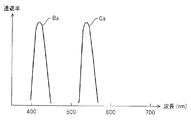
- FIG. 2 shows an example of the spectral characteristics of the narrowband filter 24.
- the narrowband filter 24 exhibits bimodal filter characteristics, and has narrowband transmission filter characteristics portions Ga and Ba, for example, in each of the green and blue wavelength regions. More specifically, the narrow band transmission filter characteristic portions Ga and Ba have bandpass characteristics with center wavelengths of 540 nm and 420 nm, respectively, and a half width of 20 to 40 nm.
- the narrow band filter 24 when the narrow band filter 24 is disposed in the illumination optical path, the two bands of narrow band illumination light that has passed through the narrow band transmission filter characteristic portions Ga and Ba are incident on the light guide 13.
- broadband white light is supplied to the light guide 13. Illumination light from the light guide 13 is transmitted to the distal end surface by the light guide 13, and is emitted to the outside through an illumination lens 27 that constitutes illumination means attached to an illumination window provided at the distal end portion 26 of the insertion portion 7. Illuminates the surface of a living tissue such as an affected part in a body cavity.
- the distal end portion 26 is provided with an observation window adjacent to the illumination window, and an objective lens 28 is attached to the observation window.
- the objective lens 28 forms an optical image by reflected light from the living tissue.
- a charge-coupled device (abbreviated as CCD) 29 is disposed at the image forming position of the objective lens 28 as a solid-state imaging device constituting the imaging means, and photoelectric conversion is performed by the CCD 29.
- a complementary color filter shown in FIG. 3 is attached to the image pickup surface of the CCD 29 for each pixel as a color separation filter 30 for optically color separation.
- This complementary color filter has four color chips of magenta (Mg), green (G), cyan (Cy), and yellow (Ye) in front of each pixel. Alternatingly arranged in the vertical direction, Mg, Cy, Mg, Ye and G, Ye, G, Cy are arranged in the order of arrangement.
- the signal read from the CCD 29 generates a luminance signal and a color difference signal by a Y / C separation circuit 37 (as a first color separation means) on the subsequent stage side as is well known.
- the CCD 29 is connected to one end of a signal line. By connecting a signal connector to which the other end of the signal line is connected to the video processor 4, the CCD driving circuit 31 and the CDS circuit 32 in the video processor 4 are connected. Connected to.
- Each endoscope 2 includes an ID generation unit 33 that generates identification information (ID) unique to the endoscope 2, and the ID generated by the ID generation unit 33 is input to the control circuit 15, and the control circuit 15 Identifies the type of endoscope 2 connected to the video processor 4 and the number and types of pixels of the CCD 29 built in the endoscope 2 by ID.
- ID identification information
- the control circuit 15 controls the CCD drive circuit 31 so as to appropriately drive the identified CCD 29 of the endoscope 2.
- the CCD 29 receives the CCD drive signal from the CCD drive circuit 31 and inputs the photoelectrically converted imaging signal to a correlated double sampling circuit (abbreviated as CDS circuit) 32.
- CDS circuit correlated double sampling circuit
- a signal component is extracted from the imaging signal by the CDS circuit 32 and converted into a baseband signal, which is then input to the A / D conversion circuit 34, converted into a digital signal, and input to the brightness detection circuit 35. , Brightness (average luminance of the signal) is detected.
- the brightness signal detected by the brightness detection circuit 35 is input to the dimming circuit 36, and a dimming signal for dimming is generated based on the difference from the reference brightness (target dimming value).
- the dimming signal from the dimming circuit 36 is input to the aperture driving circuit 23, and the aperture driving circuit 23 adjusts the opening amount of the aperture 22 so that the reference brightness is obtained.
- the digital signal output from the A / D conversion circuit 34 is input to the Y / C separation circuit 37.
- the Y / C separation circuit 37 detects the luminance signal Y and the line-sequential color difference (as the color signal C in a broad sense). Signals Cr and Cb are generated.
- the Y / C separation circuit 37 forms a first color separation means. Therefore, the luminance signal Y as the output signal of the Y / C separation circuit 37 is the first luminance signal, and the color difference signals Cr and Cb are the first color difference. Corresponds to the signal.
- the luminance signal Y is input to the enlargement circuit 47 via the ⁇ circuit 38 (this luminance signal is referred to as Yh) and is also input to a first low-pass filter (abbreviated as LPF) 41a that restricts the pass band of the signal.
- LPF 41a is set to a wide pass band corresponding to the luminance signal Y, and the luminance signal Yl of the band set by the pass band characteristic of the LPF 41a is sent to the first matrix circuit 42 as the first color conversion means. Entered.
- the color difference signals Cr and Cb are input to the synchronization circuit 43 (line-sequentially) via the second LPF 41b that limits the passband of the signal.
- the characteristics of the pass band of the second LPF 41b are changed by the control circuit 15 in accordance with the observation mode.
- the second LPF 41b is set to a lower band than the first LPF 41a. That is, in the WLI mode, it is set to perform signal processing conforming to standard video signal standards.
- the second LPF 41b is changed to a band wider than the low band in the WLI mode.
- the second LPF 41b is set (changed) in a wide band in substantially the same manner as the first LPF 41a.
- the second LPF 41b forms processing characteristic changing means for changing the processing characteristic for limiting the pass band for the color difference signals Cr and Cb in conjunction with the switching of the observation mode.
- the band characteristics of the signal passage of the second LPF 41b are widened, so that the G color signal imaged under the G illumination light that is close to the luminance state signal of the traveling state of the capillary blood vessels and the narrow band transmission filter characteristic section Ga.
- the resolution (resolution) of the blood vessel running state near the surface layer obtained by the above can be improved, and an image with good image quality that is easy to diagnose can be obtained.
- the synchronization circuit 43 generates the synchronized color difference signals Cr and Cb, and the color difference signals Cr and Cb are input to the first matrix circuit 42 as the first color conversion means.
- the first matrix circuit 42 converts the luminance signal Yl and the color difference signals Cr and Cb into the first three primary color signals R1, G1, and B1, and outputs them to the signal intensity ratio calculation circuit 44 that calculates the signal intensity ratio.
- the first three primary color signals R1, G1, and B1 are also input to a ⁇ circuit 45 that performs gamma correction.
- the first matrix circuit 42 is controlled by the control circuit 15 and changes (switches) the value of the matrix coefficient according to the characteristics of the color separation filter 30 of the CCD 29 and the characteristics of the narrowband filter 24 (determining conversion characteristics). To do. That is, the first matrix circuit 42 changes the value of the matrix coefficient to be converted into the first three primary color signals R1, G1, and B1 in accordance with the spectral characteristics of the light incident on the CCD 29 as the imaging means. Then, the first matrix circuit 42 converts the signals into three primary color signals R1, G1, and B1 that have no color mixing or almost eliminate color mixing. Note that, as described above, in the NBI mode, illumination light in the red wavelength band is not used, and thus there is no R1 color signal.
- the characteristics of the color separation filter 30 of the CCD 29 mounted on the endoscope 2 may differ depending on the endoscope 2 that is actually connected to the video processor 4.
- the matrix coefficients to be converted into the first three primary color signals R1, G1, and B1 by the first matrix circuit 42 are changed according to the characteristics of the color separation filter 30 of the CCD 29 that is actually used.
- the signal intensity ratio calculation circuit 44 calculates the signal intensity ratios s, t, u of the three primary color signals R1, G1, B1 input through the first matrix circuit 42, and the calculated signal intensity ratios s, t, Information on u is output to the control circuit 15. Therefore, the signal intensity ratio calculation circuit 44 integrates the signal levels of the first three primary color signals R1, G1, and B1 output from the first matrix circuit 42 for each field unit, and 3 based on the integration result.
- the signal intensity ratios s, t, u of the primary color signals R1, G1, B1 are calculated.
- the signal intensity ratios s, t, and u are calculated by integration within a predetermined region Rd set in an image region Ro of one field.
- the signal intensity ratio calculation circuit 44 may be provided inside the control circuit 15, for example.
- the signal intensity ratios s, t, u of the three primary color signals R1, G1, B1 are calculated for each field unit, and the third matrix circuit 49 constituting the second color separation means as will be described later.
- the matrix coefficient is dynamically changed on a field basis.
- the control circuit 15 includes a reference table 15 a that is referred to for setting matrix coefficients by the first matrix circuit 42, the second matrix circuit 46, and the third matrix circuit 49.
- the ⁇ circuit 45 is also controlled by the control circuit 15. Specifically, in the NBI mode, the ⁇ characteristics are changed to emphasize the ⁇ correction characteristics than in the WLI mode. As a result, the contrast on the low signal level side is enhanced, and the display characteristics are more easily identified.
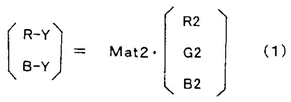
- the three primary color signals R2, G2, and B2 that have been ⁇ -corrected by the ⁇ circuit 45 are input to the second matrix circuit 46 that constitutes the second color conversion means, and the second matrix circuit 46 causes the color difference as follows. Converted to signals RY and BY.
- the matrix Mat2 is expressed as, for example, the expression (3). [Equation 1]
- the second matrix circuit 46 employs, for example, a matrix coefficient fixed to a fixed value regardless of switching of the observation mode.
- the color difference signals RY and BY output from the second matrix circuit 46 are input together with the luminance signal Yh to an enlargement circuit 47 that performs enlargement processing.
- the luminance signal Yh enlarged by the enlargement circuit 47 is subjected to edge enhancement by the enhancement circuit 48, and then input to the third matrix circuit 49, and the color difference signals RY and BY enlarged by the enlargement circuit 47. Is input to the third matrix circuit 49 without passing through the emphasis circuit 48.
- the luminance signal Yh and the color difference signals RY and BY are converted into the three primary color signals R, G, and B by the third matrix circuit 49 as the second color separation means.
- the three primary color signals R, G, and B are converted into analog video signals by a D / A conversion circuit (not shown) and output to the monitor 5 from the video signal output terminal.
- the matrix Mat3 (matrix coefficient thereof) is based on the signal intensity ratios s, t, u of the first three primary color signals R1, G1, B1 generated by the first matrix circuit 42.
- the control circuit 15 can dynamically switch. Specifically, if the matrix of 2 rows and 3 columns of the second matrix circuit 46 is Mat2, and the signal intensity ratios s, t, u of the first three primary color signals R1, G1, B1 are used, the matrix Mat3 is , [Equation 2] It is dynamically switched so that
- the matrix Mat2 is, for example, [Equation 3]. It is set like this.
- () ⁇ 1 means an inverse matrix.
- the NBI mode when the endoscopic image is displayed in color on the monitor 5, it is displayed after color conversion in order to improve the visibility compared with the case of displaying the actual color signal as it is. There is provided a color conversion setting unit 50 for performing setting.
- the surgeon When performing color conversion, the surgeon performs an operation of turning on a color conversion switch (not shown) in the color conversion setting unit 50, and the operation signal is output to the control circuit 15.
- the control circuit 15 uses, for example, a matrix element (also referred to as matrix coefficient) k1 for performing standard color conversion stored in advance in the table 15a. , K2 and k3, instead of using the matrix Mat3 of the formula (2), the matrix Mat3 of the following formula (4) is used. [Equation 4] As apparent from the above expression, the matrix Mat3 in the equation (4) is obtained by multiplying the matrix Mat3 in the equation (2) by the color conversion matrix M Trans including the matrix elements k1, k2, and k3 for color conversion.
- the surgeon may operate the color conversion setting unit 50 to variably set the values of the matrix elements k1, k2, and k3 for color conversion when performing color conversion.
- the edge enhancement by the enhancement circuit 48 is also changed via the control circuit 15 according to the type of the CCD 29, the color separation filter 30 and the like, and the enhancement characteristics (whether the enhancement band is set to the middle or low band). You may do it.
- the luminance signal Yh is emphasized, a process that emphasizes structures such as capillaries near the surface of the living body is performed, and the image component of interest can be clearly displayed.
- the signal intensity ratio s, t, u is calculated.
- the three primary color signals R, G, and B as image signals when an endoscopic image is displayed on the monitor 5 are converted into the third matrix circuit 49.
- the luminance signal Yh and the color difference signals RY and BY are generated according to the color separation processing.
- the luminance signal Yh generated by the Y / C separation circuit 37 is converted into each of the first three primary color signals R1, G1, B1 by matrix calculation using the matrix Mat3 of the third matrix circuit 49. A color separation process reflecting the signal intensity ratio is performed.
- the endoscope apparatus 1 having such a configuration separates a CCD 29 as an imaging unit that images the inside of a body cavity and a first luminance signal and a first color difference signal that are separated from a captured image captured by the imaging unit.
- a Y / C separation circuit 37 as one color separation means, and a first matrix circuit 42 as first color conversion means for converting the first three primary color signals based on the first luminance signal and the first color difference signal;
- the endoscope apparatus 1 includes a second matrix circuit 46 as a second color conversion unit that converts an output signal from the first color conversion unit into a second color difference signal, the first luminance signal, and the second luminance signal.
- step S1 as the operation mode of the light source device 3 and the video processor 4, for example, the WLI mode is set.
- the light source device 3 is set in a state in which the narrowband filter 24 is detached from the illumination optical path as shown by the solid line in FIG. 1, and performs imaging with the endoscope 2 under white illumination light. It becomes a state.
- each unit on the video processor 4 side is also set to perform signal processing in the WLI mode.
- the signal strength ratio calculation circuit 44 in the processor 4 calculates the signal strength ratios s and t for each field.
- the control circuit 15 sets the matrix Mat3 of the third matrix circuit 49 with reference to the table 15a based on the signal intensity ratios s and t.
- the third matrix circuit 49 performs matrix calculation using the matrix Mat3. By this matrix operation, the third matrix circuit 49 generates the three primary color signals R, G, and B in a state where the luminance signal Yh is color-separated according to the signal intensity ratios s, t, and u as shown in step S5. To do.
- step S6 an endoscopic image corresponding to the three primary color signals R, G, B is displayed on the monitor 5.
- the surgeon performs an endoscopic examination on a tissue to be examined such as an affected part in a body cavity while observing the endoscopic image.
- the surgeon operates the mode switch 14.
- step S7 the control circuit 15 monitors whether or not the mode change switch 14 has been operated. If the mode change switch 14 has not been operated, the control circuit 15 returns to step S2 to maintain the WLI mode state. When the changeover switch 14 is operated, the process proceeds to the next step S8.
- step S8 the control circuit 15 changes the operation mode of the light source device 3 and the video processor 4 to the setting state of the NBI mode. Specifically, the control circuit 15 controls the light source device 3 so that the narrowband filter 24 is arranged in the illumination optical path as indicated by a two-dot chain line in FIG. As shown in FIG. 2, the narrow band filter 24 is arranged in the illumination optical path so that the illumination is performed by the narrow band illumination light from the narrow band transmission filter characteristic portions Ga and Ba. In addition, the control circuit 15 changes the setting of each unit in the video processor 4. Specifically, the control circuit 15 widens the band characteristic of the LPF 41b.
- the band characteristics of the signal passing of the LPF 41b are widened, and the G color imaged under the G illumination light that is close to the luminance state signal of the traveling state of the capillary blood vessels and the narrow band transmission filter characteristic unit Ga as described above.
- the resolution (resolution) of the blood vessel running state near the surface layer obtained by the signal is improved.
- the signal strength ratio calculation circuit 44 calculates the signal strength ratio t for each field.
- the third matrix circuit 49 performs a matrix operation using the matrix Mat3. With this matrix operation, the third matrix circuit 49 performs the three primary color signals G, B or R, G, B in a state where the luminance signal Yh is color-separated according to the signal intensity ratios t, u as shown in step S12. Is generated.
- the color conversion setting unit 50 is OFF, the third matrix circuit 49 generates the three primary color signals G and B.
- the color conversion setting unit 50 is ON, the third matrix circuit 49 Three primary color signals R, G, and B are generated.
- an endoscopic image corresponding to the three primary color signals G and B or R, G and B is displayed on the monitor 5.
- the control circuit 15 monitors whether or not the mode change switch 14 has been operated. If the mode change switch 14 has not been operated, the control circuit 15 returns to the process of step S9 and maintains the state of the NBI mode. If the mode switch 14 is operated, the process returns to step S1.
- the mode change switch 14 is operated, the process returns to step S1.
- a narrow band light source device can be easily formed by providing means for inserting / removing the narrow band filter 24 in / from the optical path in addition to the normal white light illumination means.
- the matrix coefficient is changed by the third matrix circuit 49 in accordance with the calculation result of the signal intensity ratio of the signal intensity ratio calculation circuit 44 in both the WLI mode and the NBI mode. I was going.
- the matrix coefficient of the third matrix circuit 49 is changed (switched) in accordance with the calculation result of the signal strength ratio of the signal strength ratio calculation circuit 44, and in the WLI mode.
- the matrix coefficient of the third matrix circuit 49 is different in the signal intensity ratio calculation result of the signal intensity ratio calculation circuit 44, the matrix coefficient may be set to a predetermined fixed value and used at that fixed value.
- the same effect as that of the first embodiment is obtained in the NBI mode.
- the WLI mode even if the matrix coefficient of the third matrix circuit 49 is fixed, the influence of the contrast reduction due to the color separation process on the luminance signal Yh can be reduced as in the NBI mode.
- the signal intensity ratio calculation circuit 44 is set under predetermined conditions (for example, in the case of initial setting or described later). It may be set to a fixed value corresponding to the calculation result of the signal intensity ratio at the time when the white balance instruction is given.
- FIG. 6 shows a configuration of an endoscope apparatus 1B according to the second embodiment of the present invention.
- a WB switch 14b for performing an instruction operation for obtaining white balance (abbreviated as WB) is provided in the endoscope 2, for example.
- WB switch 14b may be provided in the video processor 4. Further, it may be provided in the endoscope 2 and the video processor 4.
- the WB switch 14b is operated by an operator or the like in a state where the endoscope 2 is set in a state where the endoscope 2 images a predetermined reference subject such as a white subject prepared in advance in the WLI mode. Further, even in the NBI mode, the operation is performed in a state where a predetermined reference subject prepared in advance in the NBI mode is illuminated and imaged with narrow-band illumination light.
- a common reference subject may be used in the WLI mode and the NBI mode, or different reference subjects may be used.
- the WB switch 14b sends a WB acquisition instruction signal to the control circuit 15.
- the control circuit 15 acquires information on the signal intensity ratios s, t, u calculated for the first three primary color signals R1, G1, B1 by the signal intensity ratio calculation circuit 44 at the timing when the instruction signal is input. .
- the control circuit 15 sets the matrix coefficient value of the third matrix circuit 49 as a predetermined fixed value using the information of the signal intensity ratio s, t, u (or t, u) acquired at this timing, Thereafter, unless the WB switch 14b is operated, the matrix coefficient value is controlled to be used without being changed. Therefore, in the present embodiment, the signal intensity ratio calculation circuit 44 reflects the information of the signal intensity ratio acquired under the condition for imaging the reference subject on the third matrix circuit 49 (for the luminance signal Yh). It has a function of generating three primary color signals (with color separation).
- control circuit 15 has information on the signal strength ratio s, t, u when the WB switch 14b is operated in the WLI mode and the WB switch 14b is operated in the NBI mode.
- Other configurations are the same as those of the first embodiment.
- FIG. 7 is a flowchart for explaining main operations according to this embodiment.
- the surgeon first makes initial settings. For this reason, a predetermined reference subject is prepared in step S21.
- the predetermined reference subject is set in a state of being imaged by the endoscope 2, is set to the WLI mode, and the WB switch 14b is operated.
- the signal strength ratio calculation circuit 44 calculates the signal strength ratios s and t in the field or frame when the WB switch 14b is operated, and outputs it to the control circuit 15.
- the control circuit 15 stores the values of the signal strength ratios s and t in the memory 15b.
- the control circuit 15 displays on the monitor 5 that the values of the signal strength ratios s and t are stored.
- next step S24 the surgeon operates the mode switch 14 to switch to the NBI mode.
- the operator operates the WB switch 14b in the next step S25.
- step S26 the signal strength ratio calculation circuit 44 calculates the signal strength ratio t in the field or frame when the WB switch 14b is operated, and outputs it to the control circuit 15.
- the control circuit 15 stores the value of the signal strength ratio t in the memory 15b.
- the control circuit 15 displays on the monitor 5 that the value of the signal strength ratio t has been stored. In this way, the initial setting is completed.
- step S28 the control circuit 15 sets the matrix Mat3 with reference to the values of the signal intensity ratios s and t in the WLI mode from the memory 15b and the table 15a.
- step S29 the third matrix circuit 49 performs matrix calculation using the matrix Mat3.
- An endoscopic image is displayed on the monitor 5.
- step S30 the control circuit 15 monitors whether or not the mode switch 14 has been operated. If the mode switch 14 has not been operated, the process returns to step S29, matrix calculation is performed using the same matrix Mat3, and an endoscopic image is displayed on the monitor 5.
- the surgeon further operates the mode changeover switch 14 when he wants to observe the running state of blood vessels on the surface of the tissue to be examined in more detail.
- the light source device 3 and the video processor 4 are set in the NBI mode.
- the LPF 41b is switched to a broadband characteristic.
- the control circuit 15 sets the matrix Mat3 with reference to the information of the signal intensity ratio t in the NBI mode from the memory 15b and the table 15a.
- the third matrix circuit 49 performs a matrix operation using the matrix Mat3. An endoscopic image is displayed on the monitor 5.
- step S33 the control circuit 15 monitors whether or not a mode switching operation has been performed. If the mode switching operation is not performed, the process returns to step S32, and the matrix calculation is performed using the same matrix Mat3. An endoscopic image is displayed on the monitor 5. On the other hand, when the mode switching operation is performed, the process returns to step S27, the WLI mode is set, and the above-described processing is repeated. According to the present embodiment, an endoscopic image corresponding to a case where color separation processing reflecting a signal intensity ratio in a state in which a predetermined reference subject for which the WB switch 14b is operated is imaged is displayed.
- the present embodiment performs color separation processing corresponding to a state in which a predetermined reference subject is imaged, and thus is suitable for a case where the healing state is compared over time with respect to the same lesion portion or the like.
- the present embodiment has a possibility of displaying capillaries and the like of the examination target tissue with higher contrast by selecting and setting a predetermined reference subject in the NBI mode according to the examination target tissue.
- the luminance signal Yh is subjected to color separation processing in the case of the reference subject, and is used for display as an endoscopic image 3. Since the primary color signal is generated, the contrast of the endoscopic image displayed on the monitor 5 can be prevented from being lowered.
- the WLI mode can be selected to operate in the operation mode of the second embodiment
- the NBI mode can be selected to operate in the operation mode of the first embodiment. Also good. It may also be possible to select to operate in the reverse operation mode.
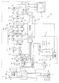
- FIG. 8 shows a configuration of an endoscope apparatus 1C according to the third embodiment of the present invention.
- the endoscope apparatus 1C according to the present embodiment does not include the signal intensity ratio calculation circuit 44 in the endoscope apparatus 1 illustrated in FIG.
- the endoscope apparatus 1C according to the present embodiment uses the matrix coefficients of the first matrix circuit 42 and the third matrix circuit 49 as the spectral sensitivity characteristics of the color separation filter 30 of the CCD 29 mounted on the endoscope 2.
- the light source device 3 or the light guide 13 of the endoscope 2 is switched according to the type, white light or narrow band light emitted from the illumination lens 27, that is, the observation mode.
- the control circuit 15 in the video processor 4 is provided in, for example, the control circuit 15 according to the combination of the determination result of the type of the CCD 29 and the observation mode based on the ID from the ID generation unit 33 of the endoscope 2.
- the matrix Mat3 of the third matrix circuit 49 is set.
- the table 15c stores data for setting a matrix Mat3 (a matrix coefficient) corresponding to the combination of the spectral sensitivity characteristic of the color separation filter 30 of the CCD 29 and the observation mode.
- the matrix of the second matrix circuit 46 is a fixed value.
- the matrix coefficient of the matrix Mat3 is a spectrum as a product of various spectral characteristics from the illumination system to the imaging system in each wavelength band of R, G, B (or G, B) in the luminance signal. Calculated (set) based on the ratio of the integral values of the products.
- the spectral sensitivity characteristics of the CCD 29 mounted on the endoscope 2 used as the endoscope apparatus, the spectral characteristics of the illumination light of the light source apparatus 3, and the illumination light from the light source apparatus 3 are transmitted. Even when the spectral characteristics of the illumination light transmission means of the light guide 13 that is emitted as illumination light from the distal end of the lever to the examination target tissue in the body cavity are different, appropriate color separation is performed for the luminance signal Yh accordingly. To give.
- Other configurations are the same as those of the first embodiment.
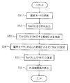
- step S41 the control circuit 15 determines the type of the CCD 29 from the ID by the ID generation unit 33 of the endoscope 2.
- step S ⁇ b> 42 the control circuit 15 grasps the observation mode that is set (selected) according to the switch operation by the mode switch 14.
- step S43 the control circuit 15 sets the matrix Mat3 of the third matrix circuit 49 with reference to the table 15c based on the type of the CCD 29 and the observation mode.
- step S ⁇ b> 44 the third matrix circuit 49 performs matrix calculation using the matrix Mat ⁇ b> 3 and generates an image signal of an endoscopic image to be displayed on the monitor 5. Then, as shown in step S45, this endoscopic image is displayed on the monitor 5.
- matrix calculation is performed by setting the matrix Mat3 of the third matrix circuit 49 according to the integration ratio of spectral products of various spectral characteristics from the illumination system to the imaging system. Therefore, even when the spectral characteristics of the CCD 29, the light source device 3, the light guide 13 and the like mounted on the endoscope 2 used as the endoscope apparatus are different, color separation corresponding to the spectral characteristics is performed with luminance. It is applied to the signal Yh. Accordingly, the function of color separation is improved, and a reduction in contrast can be prevented.
- each endoscope 2 may hold information for determining the CCD 29 mounted on the endoscope 2 and the matrix Mat3 for each observation mode.
- the control circuit 15 determines a matrix coefficient of the corresponding matrix Mat3 with reference to the table 15c based on this information.
- the third matrix circuit 49 performs matrix calculation using the matrix Mat3.
- information for determining the matrix Mat3 a case where a plurality of bits constituting an ID generated by the ID generation unit 33 includes this information will be described. That is, it is assumed that the predetermined plural bits in the ID include information for determining the matrix coefficient of the matrix Mat3.
- the schematic operation in the case of this modification is as shown in FIG.
- the control circuit 15 grasps the observation mode set (selected) according to the switch operation by the mode changeover switch 14.
- the ID generator 33 of the endoscope 2 outputs an ID including information for determining the matrix Mat3 to the control circuit 15 of the video processor 4.
- the control circuit 15 extracts a plurality of bits of data for determining the matrix coefficient of the matrix Mat3 for each observation mode from this ID.
- the control circuit 15 sets the matrix Mat3 of the third matrix circuit 49 with reference to the table 15c based on a plurality of bits of data corresponding to the current observation mode.
- the third matrix circuit 49 performs matrix calculation using the matrix Mat3 and generates an image signal of an endoscopic image to be displayed on the monitor 5. Then, as shown in step S56, this endoscopic image is displayed on the monitor 5.
- This modification has substantially the same function and effect as the third embodiment. Note that embodiments configured by partially combining the above-described embodiments and the like also belong to the present invention.
- the observation mode of the WLI mode and the NBI mode has been described.
- the present invention may be applied to an observation mode by a fluorescence mode in which fluorescence observation is performed using excitation light. .
- the matrix coefficient corresponding to the first matrix circuit is switched according to the spectral characteristics of fluorescence incident on the imaging unit of the endoscope and the characteristics of the color separation filter in the imaging unit
- the matrix coefficient of the matrix circuit corresponding to the third matrix circuit may be switched based on the signal intensity ratio of the output signal of the circuit corresponding to the first matrix circuit, and color separation processing may be performed on the luminance signal Yh.
Abstract
内視鏡装置において、色分離フィルタを備えたCCDにより撮像された信号は、Y/C分離回路により第1輝度信号と第1色差信号に分離された後、第1及び第2マトリクス回路により3原色信号と第2色差信号に変換されると共に、間に介挿された信号強度比算出回路により3原色信号の信号強度比が算出される。第1輝度信号と第2色差信号は、第3マトリクス回路により、信号強度比に応じて第1輝度信号に対する色分離を施した変換を行う。
Description
本発明は内視鏡に設けられた撮像手段に対する信号処理を行い、内視鏡画像を生成する内視鏡装置に関する。
近年においては、撮像手段を備えた電子内視鏡は、各種の内視鏡検査等において広く採用されるようになった。
電子内視鏡を用いて内視鏡検査を行う場合、白色光の照明下で、カラーの光学フィルタを備えた撮像素子を用いて、カラー撮像を行う同時式の内視鏡装置と、モノクロの撮像素子を用いてR,G,Bの面順次の照明光の下でそれぞれ撮像を行うことにより、カラー画像を生成する面順次方式の内視鏡装置とがあり、信号処理系は両者において異なる。
日本国特開2007-300972号公報の従来例には、同時式の内視鏡装置が開示されている。この従来例の図1においては、補色系のカラーフィルタを備えた撮像手段を備えた内視鏡が採用され、この撮像手段に対する信号処理装置としては、輝度信号Yと色信号CとをY/C分離回路で分離する。
電子内視鏡を用いて内視鏡検査を行う場合、白色光の照明下で、カラーの光学フィルタを備えた撮像素子を用いて、カラー撮像を行う同時式の内視鏡装置と、モノクロの撮像素子を用いてR,G,Bの面順次の照明光の下でそれぞれ撮像を行うことにより、カラー画像を生成する面順次方式の内視鏡装置とがあり、信号処理系は両者において異なる。
日本国特開2007-300972号公報の従来例には、同時式の内視鏡装置が開示されている。この従来例の図1においては、補色系のカラーフィルタを備えた撮像手段を備えた内視鏡が採用され、この撮像手段に対する信号処理装置としては、輝度信号Yと色信号CとをY/C分離回路で分離する。
また、この信号処理装置においては、輝度信号Yをローパスフィルタを通した輝度信号Ylと、ローパスフィルタを通さない輝度信号Yhとを生成している。
また、この信号処理装置においては、通常白色光観察(WLI)と、狭帯域光観察(NBI)との観察モードの切り替えに連動して、輝度信号Yhと、第2マトリクス回路46から出力されるNBIの観察モード時の輝度信号Ynbiとをセレクタ39により切り替えて後段側に出力する構成となっていた。
このため、WLIの観察モードにおける輝度信号Yhは、第2マトリクス回路46の出力信号としての輝度信号Yと乖離した状態のまま、後段側で信号処理されるため色分離が十分には行われていない。
また、この従来例におけるセレクタ39により切替を行うことなく、共通の輝度信号Yhを後段側に出力する構成にして簡素化した構成にすることが望まれる。
しかし、共通の輝度信号Yhを後段側に出力する構成にした場合にも、上記の従来例の場合と同様に、輝度信号Yhに対して、撮像手段を構成する撮像素子や照明光の分光特性に応じた色分離の処理が施されていない。
そのため、特に狭帯域光の照明下で撮像する狭帯域光観察(NBI)などにおいては、表示手段に内視鏡画像として表示した場合の画像のコントラストの低下を招く原因になっていた。
そのため、特に狭帯域光の照明下で撮像する狭帯域光観察(NBI)などにおいては、表示手段に内視鏡画像として表示した場合の画像のコントラストの低下を招く原因になっていた。
より具体的に説明すると、術者は、血管像や粘膜微細構造を詳細に観察するためにNBIの観察モードに設定する場合がある。しかし、上記の構成においては、輝度信号YhがNBIにおける色信号の画像信号と独立した状態の画像信号として表示手段に出力される。このため、血管像や粘膜微細構造のコントラスト低下を招く原因になる。
本発明は上述した点に鑑みてなされたもので、色分離を向上することによりコントラストの低下の少ない内視鏡画像を生成することができる内視鏡装置を提供することを目的とする。
本発明は上述した点に鑑みてなされたもので、色分離を向上することによりコントラストの低下の少ない内視鏡画像を生成することができる内視鏡装置を提供することを目的とする。
本発明の一態様の内視鏡装置は、体腔内を撮像する撮像手段と、前記撮像手段により撮像された撮像画像に対して第1輝度信号と第1色差信号とに分離する第1色分離手段と、前記第1輝度信号及び前記第1色差信号に基づいて第1の3原色信号に変換する第1色変換手段と、前記第1色変換手段からの出力信号を第2色差信号に変換する第2色変換手段と、前記第1輝度信号及び前記第2色変換手段からの出力信号を第2の3原色信号に変換する第2色分離手段と、前記第1色変換手段から出力される前記第1の3原色信号の強度比を算出する信号強度比算出手段と、を有し、前記信号強度比算出手段の出力結果に応じて前記第2色分離手段の処理内容を切り替えることを特徴とする。
以下、図面を参照して本発明の実施形態を説明する。
(第1の実施形態)
図1に示すように第1の実施形態の内視鏡装置1は、体腔内に挿入され、内視鏡検査を行う電子内視鏡(以下、単に内視鏡と略記)2と、この内視鏡2に照明光を供給する光源装置3とを備える。また、この内視鏡装置1は、内視鏡2に内蔵された撮像手段を駆動すると共に、撮像手段の出力信号に対する信号処理を行う内視鏡用映像信号処理装置としてのビデオプロセッサ4と、ビデオプロセッサ4から出力される映像信号が入力されることにより、撮像手段により撮像された撮像画像に対して信号処理した画像を内視鏡画像として表示するモニタ5とを備える。
(第1の実施形態)
図1に示すように第1の実施形態の内視鏡装置1は、体腔内に挿入され、内視鏡検査を行う電子内視鏡(以下、単に内視鏡と略記)2と、この内視鏡2に照明光を供給する光源装置3とを備える。また、この内視鏡装置1は、内視鏡2に内蔵された撮像手段を駆動すると共に、撮像手段の出力信号に対する信号処理を行う内視鏡用映像信号処理装置としてのビデオプロセッサ4と、ビデオプロセッサ4から出力される映像信号が入力されることにより、撮像手段により撮像された撮像画像に対して信号処理した画像を内視鏡画像として表示するモニタ5とを備える。
内視鏡2は、細長の挿入部7と、この挿入部7の後端に設けられた操作部8と、この操作部8から延出されたユニバーサルケーブル9とを有し、このユニバーサルケーブル9の端部のライトガイドコネクタ11は、光源装置3に着脱自在に接続され、信号コネクタは、ビデオプロセッサ4に着脱自在に接続される。
上記挿入部7内には、照明光を伝送するライトガイド13が挿通され、このライトガイド13における手元側の端部のライトガイドコネクタ11を光源装置3に接続することにより、光源装置3からの照明光がライトガイド13に供給される。
光源装置3は、通常白色光観察(WLIと略記)モード時には、照明光として可視波長領域をカバーする白色照明光を発生して、ライトガイド13に供給する。
上記挿入部7内には、照明光を伝送するライトガイド13が挿通され、このライトガイド13における手元側の端部のライトガイドコネクタ11を光源装置3に接続することにより、光源装置3からの照明光がライトガイド13に供給される。
光源装置3は、通常白色光観察(WLIと略記)モード時には、照明光として可視波長領域をカバーする白色照明光を発生して、ライトガイド13に供給する。
一方、狭帯域光観察(NBIと略記)モード時には、照明光として狭帯域の照明光を発生して、ライトガイド13に供給する。
WLIモードとNBIモードの切替指示は、例えば内視鏡2の操作部8に設けたスコープスイッチ等によるモード切替スイッチ14により行うことができる。なお、モード切替スイッチ14は、内視鏡2に設けたスコープスイッチで構成する他に、フットスイッチにより構成しても良いし、ビデオプロセッサ4のフロントパネルにモード切替スイッチを設けても良いし、図示しないキーボードにより構成する等しても良い。
このモード切替スイッチ14による切替信号は、ビデオプロセッサ4内の制御回路15に入力され、切替信号が入力されるとこの制御回路15は、光源装置3のフィルタ挿脱機構16を制御して、通常白色光と、狭帯域照明光とを選択的に切り替える。
また、後述するように、この制御回路15は、光源装置3からライトガイド13に供給する照明光の切替制御に連動して、ビデオプロセッサ4内の信号処理系の特性を切り替える制御も行う。そして、モード切替スイッチ14による切替操作により、信号処理系の特性を切り替えることにより、WLIモード及びNBIモードそれぞれの観察モードに適した信号処理を行えるようにしている。
光源装置3は、照明光を発生するランプ20を内蔵し、このランプ20は、可視波長領域を含む照明光を発生する。この照明光は、赤外カットフィルタ21により赤外光がカットされて略白色光の波長帯域に近い照明光にされた後、絞り22に入射される。この絞り22は、絞り駆動回路23により、開口量が調整されてその通過光量が制御される。
光源装置3は、照明光を発生するランプ20を内蔵し、このランプ20は、可視波長領域を含む照明光を発生する。この照明光は、赤外カットフィルタ21により赤外光がカットされて略白色光の波長帯域に近い照明光にされた後、絞り22に入射される。この絞り22は、絞り駆動回路23により、開口量が調整されてその通過光量が制御される。
この絞り22を通過した照明光は、プランジャなどにより構成されるフィルタ挿脱機構16により照明光路中に挿脱される狭帯域用フィルタ24を通してNBIモード時、或いは狭帯域用フィルタ24を通さないWLIモード時、集光レンズ25により集光されてライトガイド13の手元側の端面、つまり入射端面に入射される。
図2は、狭帯域用フィルタ24の分光特性の1例を示す。この狭帯域用フィルタ24は、2峰性フィルタ特性を示し、例えば、緑、青の各波長域において、それぞれ狭帯域透過フィルタ特性部Ga,Baを有する。
より具体的には、狭帯域透過フィルタ特性部Ga,Baは、それぞれ中心波長が540nm、420nmであり、その半値幅が20~40nmのバンドパス特性を有する。
図2は、狭帯域用フィルタ24の分光特性の1例を示す。この狭帯域用フィルタ24は、2峰性フィルタ特性を示し、例えば、緑、青の各波長域において、それぞれ狭帯域透過フィルタ特性部Ga,Baを有する。
より具体的には、狭帯域透過フィルタ特性部Ga,Baは、それぞれ中心波長が540nm、420nmであり、その半値幅が20~40nmのバンドパス特性を有する。
従って、狭帯域用フィルタ24が照明光路中に配置された場合には、この狭帯域透過フィルタ特性部Ga,Baを透過した2バンドの狭帯域照明光がライトガイド13に入射される。
これに対して、狭帯域用フィルタ24を照明光路中に配置しない場合には、広帯域の白色光がライトガイド13に供給されることになる。
ライトガイド13からの照明光は、ライトガイド13によりその先端面に伝送され、挿入部7の先端部26に設けた照明窓に取り付けた照明手段を構成する照明レンズ27を経て外部に出射され、体腔内の患部等の生体組織の表面を照明する。
これに対して、狭帯域用フィルタ24を照明光路中に配置しない場合には、広帯域の白色光がライトガイド13に供給されることになる。
ライトガイド13からの照明光は、ライトガイド13によりその先端面に伝送され、挿入部7の先端部26に設けた照明窓に取り付けた照明手段を構成する照明レンズ27を経て外部に出射され、体腔内の患部等の生体組織の表面を照明する。
先端部26には、照明窓に隣接して観察窓が設けてあり、この観察窓には対物レンズ28が取り付けられている。この対物レンズ28は、生体組織からの反射光による光学像を結像する。この対物レンズ28の結像位置には、撮像手段を構成する固体撮像素子として電荷結合素子(CCDと略記)29が配置されており、このCCD29により光電変換される。
このCCD29の撮像面には、光学的に色分離する色分離フィルタ30として例えば図3に示す補色系カラーフィルタが各画素単位で取り付けてある。
この補色系カラーフィルタは、各画素の前に、マゼンタ(Mg)、グリーン(G)、シアン(Cy)、イエロ(Ye)の4色のカラーチップが、水平方向には、MgとGとが交互に配置され、縦方向には、Mg、Cy、Mg、YeとG、Ye、G、Cyとの配列順で、それぞれ配置されている。
このCCD29の撮像面には、光学的に色分離する色分離フィルタ30として例えば図3に示す補色系カラーフィルタが各画素単位で取り付けてある。
この補色系カラーフィルタは、各画素の前に、マゼンタ(Mg)、グリーン(G)、シアン(Cy)、イエロ(Ye)の4色のカラーチップが、水平方向には、MgとGとが交互に配置され、縦方向には、Mg、Cy、Mg、YeとG、Ye、G、Cyとの配列順で、それぞれ配置されている。
そして、この補色系カラーフィルタを用いたCCD29の場合、縦方向に隣接する2列の画素を加算して順次読み出すが、このとき奇数フィールドと偶数フィールドで画素の列をずらして読み出すようにする。そして、CCD29から読み出された信号は、後段側での(第1の色分離手段としての)Y/C分離回路37により、公知のように輝度信号と色差信号とが生成されることになる。
上記CCD29は、信号線の一端と接続されており、この信号線の他端が接続された信号コネクタをビデオプロセッサ4に接続することにより、ビデオプロセッサ4内のCCD駆動回路31とCDS回路32とに接続される。
なお、各内視鏡2は、その内視鏡2に固有の識別情報(ID)を発生するID発生部33を備え、ID発生部33によるIDは、制御回路15に入力され、制御回路15は、IDによりビデオプロセッサ4に接続された内視鏡2の種類やその内視鏡2の内蔵されたCCD29の画素数、種類等を識別する。
上記CCD29は、信号線の一端と接続されており、この信号線の他端が接続された信号コネクタをビデオプロセッサ4に接続することにより、ビデオプロセッサ4内のCCD駆動回路31とCDS回路32とに接続される。
なお、各内視鏡2は、その内視鏡2に固有の識別情報(ID)を発生するID発生部33を備え、ID発生部33によるIDは、制御回路15に入力され、制御回路15は、IDによりビデオプロセッサ4に接続された内視鏡2の種類やその内視鏡2の内蔵されたCCD29の画素数、種類等を識別する。
そして、識別した内視鏡2のCCD29を適切に駆動するように制御回路15は、CCD駆動回路31を制御する。
CCD29は、CCD駆動回路31からのCCD駆動信号の印加により、光電変換された撮像信号は、相関二重サンプリング回路(CDS回路と略記)32に入力される。CDS回路32により、撮像信号から信号成分が抽出されてベースバンドの信号に変換された後、A/D変換回路34に入力され、デジタル信号に変換されると共に、明るさ検波回路35に入力され、明るさ(信号の平均輝度)が検出される。
明るさ検波回路35により検出された明るさ信号は、調光回路36に入力され、基準の明るさ(調光の目標値)との差分により調光するための調光信号が生成される。この調光回路36からの調光信号は、絞り駆動回路23に入力され、絞り駆動回路23は、基準となる明るさとなるように絞り22の開口量を調整する。
A/D変換回路34から出力されるデジタル信号は、Y/C分離回路37に入力され、Y/C分離回路37は、輝度信号Yと、(広義の色信号Cとしての)線順次の色差信号Cr,Cbが生成される。このY/C分離回路37は、第1の色分離手段を形成し、従って、Y/C分離回路37の出力信号としての輝度信号Yは第1輝度信号、色差信号Cr,Cbは第1色差信号に相当する。
輝度信号Yは、γ回路38を介して拡大回路47に入力される(この輝度信号をYhと記す)と共に、信号の通過帯域を制限する第1のローパスフィルタ(LPFと略記)41aに入力される。
このLPF41aは、輝度信号Yに対応して広い通過帯域に設定されており、このLPF41aの通過帯域特性により設定された帯域の輝度信号Ylが、第1色変換手段としての第1マトリクス回路42に入力される。
輝度信号Yは、γ回路38を介して拡大回路47に入力される(この輝度信号をYhと記す)と共に、信号の通過帯域を制限する第1のローパスフィルタ(LPFと略記)41aに入力される。
このLPF41aは、輝度信号Yに対応して広い通過帯域に設定されており、このLPF41aの通過帯域特性により設定された帯域の輝度信号Ylが、第1色変換手段としての第1マトリクス回路42に入力される。
また、色差信号Cr,Cbは、信号の通過帯域を制限する第2のLPF41bを介して(線順次)同時化回路43に入力される。
この場合、第2のLPF41bは、制御回路15により、観察モードに応じてその通過帯域の特性が変更される。具体的には、WLIモード時には、第2のLPF41bは、第1のLPF41aより低帯域に設定される。つまり、WLIモード時には、標準的な映像信号の規格に準拠した信号処理を行うように設定される。
一方、NBIモード時には、第2のLPF41bは、WLIモード時における低帯域よりも広い帯域に変更される。例えば第2のLPF41bは、第1のLPF41aとほぼ同様に広帯域に設定(変更)される。
このように第2のLPF41bは、観察モードの切替に連動して、色差信号Cr,Cbに対する通過帯域制限する処理特性を変更する処理特性変更手段を形成している。
第2のLPF41bの信号通過の帯域特性を広帯域化することにより、毛細血管の走行状態や、狭帯域透過フィルタ特性部Gaによる輝度信号に近いGの照明光のもとで撮像したGの色信号により得られる表層付近に近い血管走行状態などの分解能(解像度)を向上することができ、診断がし易い画質の良い画像が得られるようにしている。
同時化回路43は、同時化された色差信号Cr,Cbを生成し、この色差信号Cr,Cbは、第1色変換手段としての第1マトリクス回路42に入力される。
第1マトリクス回路42は、輝度信号Yl及び色差信号Cr,Cbから第1の3原色信号R1,G1,B1に変換して、信号強度比を算出する信号強度比算出回路44に出力する。また、第1の3原色信号R1,G1,B1は、ガンマ補正するγ回路45にも入力される。
同時化回路43は、同時化された色差信号Cr,Cbを生成し、この色差信号Cr,Cbは、第1色変換手段としての第1マトリクス回路42に入力される。
第1マトリクス回路42は、輝度信号Yl及び色差信号Cr,Cbから第1の3原色信号R1,G1,B1に変換して、信号強度比を算出する信号強度比算出回路44に出力する。また、第1の3原色信号R1,G1,B1は、ガンマ補正するγ回路45にも入力される。
この第1マトリクス回路42は、制御回路15によって制御され、CCD29の色分離フィルタ30の特性や狭帯域用フィルタ24の特性に応じて(変換特性を決定する)マトリクス係数の値を変更(切替)する。つまり、第1マトリクス回路42は、撮像手段としてのCCD29に入射する光の分光特性に応じて、第1の3原色信号R1,G1,B1に変換するマトリクス係数をの値を変更する。そして、第1マトリクス回路42は、混色の無い或いは混色を殆ど解消した3原色信号R1,G1,B1に変換する。なお、上述したように、NBIモードにおいては、赤の波長帯域の照明光を用いないので、R1の色信号を有しない。
例えば、ビデオプロセッサ4に実際に接続される内視鏡2により、その内視鏡2に搭載されているCCD29の色分離フィルタ30の特性が異なる場合があり、制御回路15は、IDの情報により実際に使用されているCCD29の色分離フィルタ30の特性に応じて第1マトリクス回路42により第1の3原色信号R1,G1,B1に変換するマトリクス係数を変更する。
例えば、ビデオプロセッサ4に実際に接続される内視鏡2により、その内視鏡2に搭載されているCCD29の色分離フィルタ30の特性が異なる場合があり、制御回路15は、IDの情報により実際に使用されているCCD29の色分離フィルタ30の特性に応じて第1マトリクス回路42により第1の3原色信号R1,G1,B1に変換するマトリクス係数を変更する。
このようにすることにより、実際に使用される撮像手段の種類が異なる場合にも適切に対応でき、偽色の発生を防止したり、混色の少ない第1の3原色信号R1,G1,B1に変換することができる。
また、信号強度比算出回路44は、第1マトリクス回路42を経て入力される3原色信号R1,G1,B1の信号強度比s,t,uを算出し、算出した信号強度比s,t,uの情報を制御回路15に出力する。
このため、信号強度比算出回路44は、第1マトリクス回路42から出力される第1の3原色信号R1,G1,B1の各信号レベルをそれぞれフィールド単位で積算して、積算結果を元に3原色信号R1,G1,B1の各信号強度比s,t,uを算出する。
この場合、例えば図4に示すように1フィールドの画像領域Ro内に設定された所定領域Rd内で積算して各信号強度比s,t,uを算出する。なお、信号強度比算出回路44を、例えば制御回路15の内部に設けるようにしても良い。
所定領域Rd内での3原色信号R1,G1,B1の積算値をそれぞれiR,iG,iBとすると、各信号強度比s,t,uは、
s=iR/(iR+iG+iB)
t=iG/(iR+iG+iB)
u=iB/(iR+iG+iB)
となり、s+t+u=1の条件を満たす。このため、s,t,uの3つを算出しないで、これら3つのうちの2つを算出し、s+t+u=1の条件から残りの1つを算出しても良い。
また、NBIモード時には、R1の色信号は0となるので、s=0となる。この場合には、t,uの2つを算出するか、2つのうちの1つを算出し、t+u=1の条件から残りの1つを算出しても良い。
s=iR/(iR+iG+iB)
t=iG/(iR+iG+iB)
u=iB/(iR+iG+iB)
となり、s+t+u=1の条件を満たす。このため、s,t,uの3つを算出しないで、これら3つのうちの2つを算出し、s+t+u=1の条件から残りの1つを算出しても良い。
また、NBIモード時には、R1の色信号は0となるので、s=0となる。この場合には、t,uの2つを算出するか、2つのうちの1つを算出し、t+u=1の条件から残りの1つを算出しても良い。
本実施形態においては、各フィールド単位で3原色信号R1,G1,B1の各信号強度比s,t,uを算出し、後述するように第2の色分離手段を構成する第3マトリクス回路49のマトリクス係数をフィールド単位で動的に変更する。
なお、制御回路15は、第1マトリクス回路42,第2マトリクス回路46,第3マトリクス回路49によるマトリクス係数を設定するために参照する参照用のテーブル15aを内蔵している。
γ回路45も、制御回路15により制御される。具体的には、NBIモード時には、WLIモード時よりもγ補正の特性を強調したγ特性に変更される。これにより、低信号レベル側でのコントラストが強調され、より識別し易い表示特性となる。
このγ回路45によりγ補正された3原色信号R2,G2,B2は、第2の色変換手段を構成する第2マトリクス回路46に入力され、この第2マトリクス回路46により、以下のように色差信号R-Y、B-Yに変換される。なお、マトリクスMat2は、例えば(3)式のように表される。
[数1]
 この第2マトリクス回路46は、観察モードの切り替えによらず、例えば固定値に固定されたマトリクス係数が採用される。
第2マトリクス回路46により出力される色差信号R-Y、B-Yは、輝度信号Yhと共に、拡大処理を行う拡大回路47に入力される。
この拡大回路47により拡大処理された輝度信号Yhは、強調回路48により輪郭強調された後、第3マトリクス回路49に入力され、拡大回路47により拡大処理された色差信号R-Y,B-Yは、強調回路48を通さないで第3マトリクス回路49に入力される。
第2の色分離手段としての第3マトリクス回路49により、輝度信号Yhと色差信号R-Y,B-Yは、3原色信号R,G,Bに変換される。この3原色信号R,G,Bは、図示しないD/A変換回路によりアナログの映像信号に変換されて映像信号出力端からモニタ5に出力される。
なお、制御回路15は、第1マトリクス回路42,第2マトリクス回路46,第3マトリクス回路49によるマトリクス係数を設定するために参照する参照用のテーブル15aを内蔵している。
γ回路45も、制御回路15により制御される。具体的には、NBIモード時には、WLIモード時よりもγ補正の特性を強調したγ特性に変更される。これにより、低信号レベル側でのコントラストが強調され、より識別し易い表示特性となる。
このγ回路45によりγ補正された3原色信号R2,G2,B2は、第2の色変換手段を構成する第2マトリクス回路46に入力され、この第2マトリクス回路46により、以下のように色差信号R-Y、B-Yに変換される。なお、マトリクスMat2は、例えば(3)式のように表される。
[数1]
第2マトリクス回路46により出力される色差信号R-Y、B-Yは、輝度信号Yhと共に、拡大処理を行う拡大回路47に入力される。
この拡大回路47により拡大処理された輝度信号Yhは、強調回路48により輪郭強調された後、第3マトリクス回路49に入力され、拡大回路47により拡大処理された色差信号R-Y,B-Yは、強調回路48を通さないで第3マトリクス回路49に入力される。
第2の色分離手段としての第3マトリクス回路49により、輝度信号Yhと色差信号R-Y,B-Yは、3原色信号R,G,Bに変換される。この3原色信号R,G,Bは、図示しないD/A変換回路によりアナログの映像信号に変換されて映像信号出力端からモニタ5に出力される。
第3のマトリクス回路49は、そのマトリクスMat3(のマトリクス係数)が、第1マトリクス回路42により生成される第1の3原色信号R1,G1,B1の各信号強度比s,t,uに基づいて、制御回路15により動的に切り替えられる。
具体的には、第2マトリクス回路46の2行3列のマトリクスをMat2とし、上記第1の3原色信号R1,G1,B1の各信号強度比s,t,uを用いると、マトリクスMat3は、
[数2]
 となるように動的に切り替えられる。
具体的には、第2マトリクス回路46の2行3列のマトリクスをMat2とし、上記第1の3原色信号R1,G1,B1の各信号強度比s,t,uを用いると、マトリクスMat3は、
[数2]
ここで、マトリクスMat2は、例えば
[数3]
 のように設定される。ここで、( )-1 は逆マトリクスを意味する。
また、本実施形態においては、NBIモード時においては、内視鏡画像をモニタ5にカラー表示する場合、実際の色信号のまま表示する場合よりも視認性を向上するために色変換して表示させる設定を行う色変換設定部50が設けてある。
[数3]
また、本実施形態においては、NBIモード時においては、内視鏡画像をモニタ5にカラー表示する場合、実際の色信号のまま表示する場合よりも視認性を向上するために色変換して表示させる設定を行う色変換設定部50が設けてある。
術者は、色変換を行う場合には、この色変換設定部50における図示しない色変換スイッチをONにする操作を行い、その操作信号は制御回路15に出力される。
この色変換設定部50により色変換を行う指示がされた場合、制御回路15は、例えばテーブル15a内に予め格納されている標準的な色変換を行うためのマトリクス要素(マトリクス係数とも言う)k1,k2,k3を参照して、(2)式のマトリクスMat3を用いる代わりに、以下の(4)式のマトリクスMat3を用いる。
[数4]
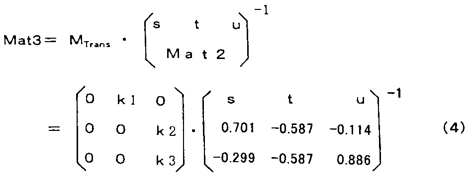 上記の表式から明らかなように(4)式におけるマトリクスMat3は、(2)式におけるマトリクスMat3に色変換用のマトリクス要素k1,k2,k3を含む色変換マトリクスMTransを乗算したものとなっている。但し、NBIモード時において、(3)式における信号強度比sはゼロである(つまりs=0)。
なお、術者は、色変換設定部50を操作して、色変換を行う場合の色変換用のマトリクス要素k1,k2,k3の値を可変設定することができるようにしても良い。
また、強調回路48による輪郭強調も、制御回路15を介してCCD29及び色分離フィルタ30等の種類に応じてその強調特性(強調帯域が中低帯域にするか中高帯域にするか)等を変更しても良い。
特にNBIモード時には、輝度信号Yhが強調処理されるようにすると、生体表層付近の毛細血管等の構造を強調した処理を行うことになり、注目する画像成分を明瞭に表示できるようになる。
この色変換設定部50により色変換を行う指示がされた場合、制御回路15は、例えばテーブル15a内に予め格納されている標準的な色変換を行うためのマトリクス要素(マトリクス係数とも言う)k1,k2,k3を参照して、(2)式のマトリクスMat3を用いる代わりに、以下の(4)式のマトリクスMat3を用いる。
[数4]
なお、術者は、色変換設定部50を操作して、色変換を行う場合の色変換用のマトリクス要素k1,k2,k3の値を可変設定することができるようにしても良い。
また、強調回路48による輪郭強調も、制御回路15を介してCCD29及び色分離フィルタ30等の種類に応じてその強調特性(強調帯域が中低帯域にするか中高帯域にするか)等を変更しても良い。
特にNBIモード時には、輝度信号Yhが強調処理されるようにすると、生体表層付近の毛細血管等の構造を強調した処理を行うことになり、注目する画像成分を明瞭に表示できるようになる。
このように本実施形態においては、観察モードの切替に連動して、各フィールド毎に所定領域Rdでの第1マトリクス回路42の出力信号としての第1の3原色信号R1,G1,B1の各信号強度比s,t,uを算出する。
そして、算出された各信号強度比s,t,uを用いて、モニタ5に内視鏡画像を表示する場合のその画像信号としての3原色信号R,G,Bが、第3マトリクス回路49により、輝度信号Yhと色差信号R-Y,B-Yの色分離処理に応じて生成されるようにしている。つまり、本実施形態においては、Y/C分離回路37により生成された輝度信号Yhは、第3マトリクス回路49のマトリクスMat3を用いたマトリクス演算により第1の3原色信号R1,G1,B1の各信号強度比を反映した色分離処理が施される。
そして、算出された各信号強度比s,t,uを用いて、モニタ5に内視鏡画像を表示する場合のその画像信号としての3原色信号R,G,Bが、第3マトリクス回路49により、輝度信号Yhと色差信号R-Y,B-Yの色分離処理に応じて生成されるようにしている。つまり、本実施形態においては、Y/C分離回路37により生成された輝度信号Yhは、第3マトリクス回路49のマトリクスMat3を用いたマトリクス演算により第1の3原色信号R1,G1,B1の各信号強度比を反映した色分離処理が施される。
このような構成の内視鏡装置1は、体腔内を撮像する撮像手段としてのCCD29と、前記撮像手段により撮像された撮像画像に対して第1輝度信号と第1色差信号とに分離する第1色分離手段としてのY/C分離回路37と、前記第1輝度信号及び前記第1色差信号に基づいて第1の3原色信号に変換する第1色変換手段としての第1マトリクス回路42とを有する。
また、内視鏡装置1は、前記第1色変換手段からの出力信号を第2色差信号に変換する第2色変換手段としての第2マトリクス回路46と、前記第1輝度信号及び前記第2色変換手段からの出力信号を第2の3原色信号に変換する第2色分離手段としての第3マトリクス回路49と、前記第1色変換手段から出力される前記第1の3原色信号の強度比を算出する信号強度比算出手段としての信号強度比算出回路44と、を有し、前記信号強度比算出手段の出力結果に応じて前記第2色分離手段の処理内容を切り替えることを特徴とする。
また、内視鏡装置1は、前記第1色変換手段からの出力信号を第2色差信号に変換する第2色変換手段としての第2マトリクス回路46と、前記第1輝度信号及び前記第2色変換手段からの出力信号を第2の3原色信号に変換する第2色分離手段としての第3マトリクス回路49と、前記第1色変換手段から出力される前記第1の3原色信号の強度比を算出する信号強度比算出手段としての信号強度比算出回路44と、を有し、前記信号強度比算出手段の出力結果に応じて前記第2色分離手段の処理内容を切り替えることを特徴とする。
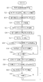
本実施形態による主要な動作を図5を参照して以下に説明する。
術者は、図1に示すように内視鏡2を光源装置3及びビデオプロセッサ4に接続し、電源を投入することにより、ビデオプロセッサ4の制御回路15は、初期設定の処理を開始し、ステップS1に示すように、光源装置3及びビデオプロセッサ4の動作モードとして、例えばWLIモードの設定状態にする。
この状態において、光源装置3は、図1の実線で示すように狭帯域用フィルタ24が照明光路から離脱された状態に設定され、白色照明光のもとで、内視鏡2により撮像を行う状態となる。また、ビデオプロセッサ4側の各部もWLIモードの状態で信号処理を行う設定状態になる。
術者は、図1に示すように内視鏡2を光源装置3及びビデオプロセッサ4に接続し、電源を投入することにより、ビデオプロセッサ4の制御回路15は、初期設定の処理を開始し、ステップS1に示すように、光源装置3及びビデオプロセッサ4の動作モードとして、例えばWLIモードの設定状態にする。
この状態において、光源装置3は、図1の実線で示すように狭帯域用フィルタ24が照明光路から離脱された状態に設定され、白色照明光のもとで、内視鏡2により撮像を行う状態となる。また、ビデオプロセッサ4側の各部もWLIモードの状態で信号処理を行う設定状態になる。
ステップS2に示すようにプロセッサ4内の信号強度比算出回路44は、各フィールド毎に信号強度比s、tを算出する。
ステップS3に示すように制御回路15は、信号強度比s、tを元にテーブル15aを参照して第3マトリクス回路49のマトリクスMat3の設定を行う。この場合には、信号強度比uはs+t+u=1の条件から算出する。ステップS4に示すように第3マトリクス回路49は、マトリクスMat3を用いてマトリクス演算を行う。このマトリクス演算により、ステップS5に示すように信号強度比s,t,uに応じて輝度信号Yhが色分離処理された状態で第3マトリクス回路49は、3原色信号R,G,Bを生成する。
ステップS3に示すように制御回路15は、信号強度比s、tを元にテーブル15aを参照して第3マトリクス回路49のマトリクスMat3の設定を行う。この場合には、信号強度比uはs+t+u=1の条件から算出する。ステップS4に示すように第3マトリクス回路49は、マトリクスMat3を用いてマトリクス演算を行う。このマトリクス演算により、ステップS5に示すように信号強度比s,t,uに応じて輝度信号Yhが色分離処理された状態で第3マトリクス回路49は、3原色信号R,G,Bを生成する。
そして、ステップS6に示すようにモニタ5には、3原色信号R,G,Bに対応した内視鏡画像が表示される。術者は、この内視鏡画像を観察しながら体腔内の患部等、検査対象組織に対する内視鏡検査を行う。
術者は、検査対象組織の表面の血管の走行状態等をより詳しく観察しようと思う場合には、術者は、モード切替スイッチ14を操作する。
ステップS7に示すように制御回路15は、モード切替スイッチ14が操作されたか否かをモニタし、モード切替スイッチ14が操作されていない場合には、ステップS2に戻りWLIモード状態を維持し、モード切替スイッチ14が操作された場合には、次のステップS8に進む。
術者は、検査対象組織の表面の血管の走行状態等をより詳しく観察しようと思う場合には、術者は、モード切替スイッチ14を操作する。
ステップS7に示すように制御回路15は、モード切替スイッチ14が操作されたか否かをモニタし、モード切替スイッチ14が操作されていない場合には、ステップS2に戻りWLIモード状態を維持し、モード切替スイッチ14が操作された場合には、次のステップS8に進む。
ステップS8においては、制御回路15は、光源装置3及びビデオプロセッサ4の動作モードをNBIモードの設定状態に変更する。
具体的には、制御回路15は、光源装置3に対しては、図1における2点鎖線で示すように狭帯域用フィルタ24を照明光路中に配置するように制御する。図2にその透過特性を示すように狭帯域用フィルタ24が照明光路中に配置されることにより、狭帯域透過フィルタ特性部Ga,Baによる狭帯域照明光により、照明が行われる。
また、制御回路15は、ビデオプロセッサ4における各部の設定を変更する、具体的には、制御回路15は、LPF41bの帯域特性を広帯域化する。
具体的には、制御回路15は、光源装置3に対しては、図1における2点鎖線で示すように狭帯域用フィルタ24を照明光路中に配置するように制御する。図2にその透過特性を示すように狭帯域用フィルタ24が照明光路中に配置されることにより、狭帯域透過フィルタ特性部Ga,Baによる狭帯域照明光により、照明が行われる。
また、制御回路15は、ビデオプロセッサ4における各部の設定を変更する、具体的には、制御回路15は、LPF41bの帯域特性を広帯域化する。
また、LPF41bの信号通過の帯域特性を広帯域化して、上記のように毛細血管の走行状態や、狭帯域透過フィルタ特性部Gaによる輝度信号に近いGの照明光のもとで撮像したGの色信号により得られる表層付近に近い血管走行状態などの分解能(解像度)を向上する。
次のステップS9において信号強度比算出回路44は、各フィールド毎に信号強度比tを算出する。
次のステップS10に示すように制御回路15は、信号強度比tを元にテーブルを参照して第3マトリクス回路49のマトリクスMat3の設定を行う。この場合には、信号強度比uはt+u=1の条件から算出する。
次のステップS9において信号強度比算出回路44は、各フィールド毎に信号強度比tを算出する。
次のステップS10に示すように制御回路15は、信号強度比tを元にテーブルを参照して第3マトリクス回路49のマトリクスMat3の設定を行う。この場合には、信号強度比uはt+u=1の条件から算出する。
ステップS11に示すように第3マトリクス回路49は、マトリクスMat3を用いてマトリクス演算を行う。このマトリクス演算により、ステップS12に示すように信号強度比t,uに応じて輝度信号Yhが色分離処理された状態で第3マトリクス回路49は、3原色信号G,B又はR,G,Bを生成する。
なお、色変換設定部50がOFFの場合には、第3マトリクス回路49は、3原色信号G,Bを生成し、色変換設定部50がONの場合には、第3マトリクス回路49は、3原色信号R,G,Bを生成する。
そして、ステップS13に示すようにモニタ5には、3原色信号G,B又はR,G,Bに対応した内視鏡画像が表示される。
なお、色変換設定部50がOFFの場合には、第3マトリクス回路49は、3原色信号G,Bを生成し、色変換設定部50がONの場合には、第3マトリクス回路49は、3原色信号R,G,Bを生成する。
そして、ステップS13に示すようにモニタ5には、3原色信号G,B又はR,G,Bに対応した内視鏡画像が表示される。
術者は、この内視鏡画像を観察しながら体腔内の検査対象組織の表面付近の毛細血管の走行状態をより詳細に観察し易い状態に設定して内視鏡検査を行う。
次のステップS14において制御回路15は、モード切替スイッチ14が操作されたか否かをモニタし、モード切替スイッチ14が操作されていない場合には、ステップS9の処理に戻り、NBIモードの状態を維持し、モード切替スイッチ14が操作された場合には、ステップS1に戻ることになる。
このように動作する本実施形態によれば、WLIモードにおいて、既存の同時式によるカラー撮像機能を保持し、かつNBIモードにおいてもビデオプロセッサ4内の各部の係数等の設定を変更する等の処理特性を変更することにより、NBIモードによる観察機能を十分に確保することができる。
次のステップS14において制御回路15は、モード切替スイッチ14が操作されたか否かをモニタし、モード切替スイッチ14が操作されていない場合には、ステップS9の処理に戻り、NBIモードの状態を維持し、モード切替スイッチ14が操作された場合には、ステップS1に戻ることになる。
このように動作する本実施形態によれば、WLIモードにおいて、既存の同時式によるカラー撮像機能を保持し、かつNBIモードにおいてもビデオプロセッサ4内の各部の係数等の設定を変更する等の処理特性を変更することにより、NBIモードによる観察機能を十分に確保することができる。
つまり、解像度の良好な内視鏡画像が得られると共に、狭帯域照明光のもとで撮像した毛細血管の走行状態をより明瞭に識別し易い状態で表示することができる。
また、本実施形態においては、被写体によって変化する第1の3原色信号R1,G1,B1の各信号強度比s,t,uに応じた色分離処理を輝度信号Yhに対しても行うようにしているので、NBIモードにおいても色分離機能が向上し、NBIモードでのコントラスト低下を防止できる。
また、本実施形態によれば、信号処理系における一部の処理特性を切り替えることにより、WLIモードとNBIモードとの両方に簡単に対応できるので、内視鏡検査の際に非常に便利かつ有用な装置となる。
また、本実施形態においては、被写体によって変化する第1の3原色信号R1,G1,B1の各信号強度比s,t,uに応じた色分離処理を輝度信号Yhに対しても行うようにしているので、NBIモードにおいても色分離機能が向上し、NBIモードでのコントラスト低下を防止できる。
また、本実施形態によれば、信号処理系における一部の処理特性を切り替えることにより、WLIモードとNBIモードとの両方に簡単に対応できるので、内視鏡検査の際に非常に便利かつ有用な装置となる。
また、光源装置3においても、通常白色光の照明手段の他に、狭帯域用フィルタ24を光路中に挿脱する手段を設けることにより、簡単に狭帯域光の光源装置を形成できる。
なお、上述した第1の実施形態の説明においては、WLIモード時及びNBIモード時とも、信号強度比算出回路44の信号強度比の算出結果に応じて第3マトリクス回路49によるマトリクス係数の変更を行っていた。
第1の実施形態の変形例として、NBIモード時のみ、信号強度比算出回路44の信号強度比の算出結果に応じて第3マトリクス回路49のマトリクス係数の変更(切替)を行い、WLIモード時においては第3マトリクス回路49のマトリクス係数を信号強度比算出回路44の信号強度比の算出結果が異なる場合にも、所定の固定値に設定してその固定値で使用しても良い。
なお、上述した第1の実施形態の説明においては、WLIモード時及びNBIモード時とも、信号強度比算出回路44の信号強度比の算出結果に応じて第3マトリクス回路49によるマトリクス係数の変更を行っていた。
第1の実施形態の変形例として、NBIモード時のみ、信号強度比算出回路44の信号強度比の算出結果に応じて第3マトリクス回路49のマトリクス係数の変更(切替)を行い、WLIモード時においては第3マトリクス回路49のマトリクス係数を信号強度比算出回路44の信号強度比の算出結果が異なる場合にも、所定の固定値に設定してその固定値で使用しても良い。
このようにした場合、NBIモード時においては第1の実施形態と同様の作用効果となる。一方、WLIモード時においては、第3マトリクス回路49のマトリクス係数を固定しても、NBIモード時ほどには輝度信号Yhに対する色分離処理によるコントラスト低下の影響を低減できる。
なお、上記のようにWLIモード時においては第3マトリクス回路49のマトリクス係数を所定の固定値に設定する場合、信号強度比算出回路44による所定の条件下(例えば初期設定の場合や、後述するホワイトバランス指示がされたタイミング等の場合)での信号強度比の算出結果に対応した固定値に設定しても良い。
なお、上記のようにWLIモード時においては第3マトリクス回路49のマトリクス係数を所定の固定値に設定する場合、信号強度比算出回路44による所定の条件下(例えば初期設定の場合や、後述するホワイトバランス指示がされたタイミング等の場合)での信号強度比の算出結果に対応した固定値に設定しても良い。
(第2の実施形態)
次に本発明の第2の実施形態を説明する。図6は本発明の第2の実施形態の内視鏡装置1Bの構成を示す。この内視鏡装置1Bは、図1の内視鏡装置1において、ホワイトバランス(WBと略記)取得の指示操作を行うWBスイッチ14bが例えば内視鏡2に設けてある。なお、WBスイッチ14bを、ビデオプロセッサ4に設けるようにしても良い。また、内視鏡2とビデオプロセッサ4に設けるようにしても良い。
なお、このWBスイッチ14bは、WLIモード時には予め用意されている白色被写体等の所定の基準被写体を内視鏡2が撮像する状態に設定された状態で、術者等により操作される。
また、NBIモード時においてもNBIモード時に予め用意されている所定の基準被写体を狭帯域の照明光で照明及び撮像する状態で、操作される。
この場合、WLIモード時と、NBIモード時において、共通の基準被写体を用いても良いし、異なる基準被写体を用いても良い。以下の説明では、簡単化のために共通の基準被写体を用いる例で説明する。
術者等の操作者がこのWBスイッチ14bを操作すると、WBスイッチ14bは、WB取得の指示信号を制御回路15に送る。制御回路15は、この指示信号が入力されたタイミングにおいて信号強度比算出回路44により第1の3原色信号R1,G1,B1に対して算出した信号強度比s,t,uの情報を取得する。
なお、上述した実施形態と同様に、WLIモード時には信号強度比s,t,u(s+t+u=1の条件を含めると2つの)情報を用いることになるが、NBIモード時においては信号強度比t,u(t+u=1の条件を含めると1つの)情報を用いることになる。
術者等の操作者がこのWBスイッチ14bを操作すると、WBスイッチ14bは、WB取得の指示信号を制御回路15に送る。制御回路15は、この指示信号が入力されたタイミングにおいて信号強度比算出回路44により第1の3原色信号R1,G1,B1に対して算出した信号強度比s,t,uの情報を取得する。
なお、上述した実施形態と同様に、WLIモード時には信号強度比s,t,u(s+t+u=1の条件を含めると2つの)情報を用いることになるが、NBIモード時においては信号強度比t,u(t+u=1の条件を含めると1つの)情報を用いることになる。
そして、制御回路15は、このタイミングで取得した信号強度比s,t,u(又はt,u)の情報を用いて第3マトリクス回路49のマトリクス係数の値を所定の固定値として設定し、以後はWBスイッチ14bが操作されない限り、そのマトリクス係数の値を変更しないで使用するように制御する。
従って、本実施形態においては、信号強度比算出回路44は、第3マトリクス回路49に対して、基準被写体を撮像させる条件下で取得した信号強度比の情報を反映した状態で(輝度信号Yhに対する色分離を施した)3原色信号を生成する機能を持つ。
また、本実施形態においては、例えば制御回路15は、WLIモード時においてWBスイッチ14bが操作された場合の信号強度比s,t,uの情報と、NBIモード時においてWBスイッチ14bが操作された場合の信号強度比t,uの情報とを記憶するメモリ15bを有する。その他の構成は第1の実施形態と同様である。
従って、本実施形態においては、信号強度比算出回路44は、第3マトリクス回路49に対して、基準被写体を撮像させる条件下で取得した信号強度比の情報を反映した状態で(輝度信号Yhに対する色分離を施した)3原色信号を生成する機能を持つ。
また、本実施形態においては、例えば制御回路15は、WLIモード時においてWBスイッチ14bが操作された場合の信号強度比s,t,uの情報と、NBIモード時においてWBスイッチ14bが操作された場合の信号強度比t,uの情報とを記憶するメモリ15bを有する。その他の構成は第1の実施形態と同様である。
図7は本実施形態による主要な動作説明のためのフローチャートを示す。
術者は、まず、初期設定を行う。このため、ステップS21において、所定の基準被写体を用意する。次のステップS22において、この所定の基準被写体を内視鏡2により撮像する状態に設定して、WLIモードに設定して、WBスイッチ14bを操作する。
すると、ステップS23に示すように信号強度比算出回路44は、WBスイッチ14bが操作された時のフィールド又はフレームにおいて信号強度比s、tを算出し、制御回路15に出力する。制御回路15は、信号強度比s、tの値をメモリ15bに記憶する。制御回路15は、信号強度比s、tの値を記憶した旨をモニタ5に表示する。
術者は、まず、初期設定を行う。このため、ステップS21において、所定の基準被写体を用意する。次のステップS22において、この所定の基準被写体を内視鏡2により撮像する状態に設定して、WLIモードに設定して、WBスイッチ14bを操作する。
すると、ステップS23に示すように信号強度比算出回路44は、WBスイッチ14bが操作された時のフィールド又はフレームにおいて信号強度比s、tを算出し、制御回路15に出力する。制御回路15は、信号強度比s、tの値をメモリ15bに記憶する。制御回路15は、信号強度比s、tの値を記憶した旨をモニタ5に表示する。
次のステップS24において術者はモード切替スイッチ14を操作して、NBIモードに切り替える。NBIモードに切り替えた後、次のステップS25において術者はWBスイッチ14bを操作する。
すると、ステップS26に示すように信号強度比算出回路44は、WBスイッチ14bが操作された時のフィールド又はフレームにおいて信号強度比tを算出し、制御回路15に出力する。制御回路15は、信号強度比tの値をメモリ15bに記憶する。制御回路15は、信号強度比tの値を記憶した旨をモニタ5に表示する。このようにして初期設定を終了する。
すると、ステップS26に示すように信号強度比算出回路44は、WBスイッチ14bが操作された時のフィールド又はフレームにおいて信号強度比tを算出し、制御回路15に出力する。制御回路15は、信号強度比tの値をメモリ15bに記憶する。制御回路15は、信号強度比tの値を記憶した旨をモニタ5に表示する。このようにして初期設定を終了する。
次に内視鏡検査を開始する。このため、術者は、例えばモード切替スイッチ14を操作してWLIモードに設定する。光源装置3及びビデオプロセッサ4はWLIモードの設定状態になる。
また、ステップS28に示すように制御回路15は、メモリ15bからWLIモードの信号強度比s、tの値と、テーブル15aを参照して、マトリクスMat3を設定する。ステップS29に示すように第3マトリクス回路49は、マトリクスMat3を用いてマトリクス演算を行う。そして、モニタ5には内視鏡画像が表示される。
ステップS30において制御回路15はモード切替スイッチ14が操作されたか否かを監視する。モード切替スイッチ14が操作されていないと、ステップS29に戻り、同じマトリクスMat3を用いてマトリクス演算を行い、モニタ5には内視鏡画像が表示される。
また、ステップS28に示すように制御回路15は、メモリ15bからWLIモードの信号強度比s、tの値と、テーブル15aを参照して、マトリクスMat3を設定する。ステップS29に示すように第3マトリクス回路49は、マトリクスMat3を用いてマトリクス演算を行う。そして、モニタ5には内視鏡画像が表示される。
ステップS30において制御回路15はモード切替スイッチ14が操作されたか否かを監視する。モード切替スイッチ14が操作されていないと、ステップS29に戻り、同じマトリクスMat3を用いてマトリクス演算を行い、モニタ5には内視鏡画像が表示される。
術者はさらに検査対象組織の表面の血管の走行状態等をより詳しく観察しようと思う場合には、モード切替スイッチ14を操作する。すると、ステップS31に示すように光源装置3及びビデオプロセッサ4はNBIモードの設定状態になる。なお、LPF41bは、広帯域の特性に切り替えられる。
また、ステップS32に示すように制御回路15は、メモリ15bからNBIモードの信号強度比tの情報と、テーブル15aを参照して、マトリクスMat3を設定する。ステップS32に示すように第3マトリクス回路49は、マトリクスMat3を用いてマトリクス演算を行う。そして、モニタ5には内視鏡画像が表示される。
また、ステップS32に示すように制御回路15は、メモリ15bからNBIモードの信号強度比tの情報と、テーブル15aを参照して、マトリクスMat3を設定する。ステップS32に示すように第3マトリクス回路49は、マトリクスMat3を用いてマトリクス演算を行う。そして、モニタ5には内視鏡画像が表示される。
また、ステップS33に示すように制御回路15は、モード切替の操作が行われたか否かを監視する。モード切替の操作が行われないと、ステップS32に戻り、同じマトリクスMat3を用いてマトリクス演算を行う。そして、モニタ5には内視鏡画像が表示される。一方、モード切替の操作が行われると、ステップS27に戻りWLIモードに設定されて上述した処理が繰り返される。
本実施形態によれば、WBスイッチ14bが操作された所定の基準被写体を撮像する状態における信号強度比を反映した色分離処理を施した場合に対応した内視鏡画像を表示する。
本実施形態によれば、WBスイッチ14bが操作された所定の基準被写体を撮像する状態における信号強度比を反映した色分離処理を施した場合に対応した内視鏡画像を表示する。
このように本実施形態は、所定の基準被写体を撮像する状態に対応した色分離処理を行うため、同じ病変部などに対して、経時的に治癒の状態を比較するような場合に適する。
また、本実施形態は、NBIモード時における所定の基準被写体を検査対象組織に応じて選択設定することにより、検査対象組織の毛細血管等をより高いコントラストで表示することも可能性を有する。
また、第1の実施形態の場合と同様に、本実施形態においても基準被写体の場合において輝度信号Yhに対して、色分離処理を施すようにして、内視鏡画像として表示に使用される3原色信号を生成するようにしているので、モニタ5に表示される内視鏡画像のコントラスト低下を防止できる。
なお、第1の実施形態と第2の実施形態との動作モードを選択できるようにしても良い。例えば、WLIモード時に対しては、第2の実施形態の動作モードで動作するように選択し、NBIモード時に対しては、第1の実施形態の動作モードで動作するように選択できるようにしても良い。また、この逆の動作モードで動作するように選択できるようにしても良い。
(第3の実施形態)
次に本発明の第3の実施形態を説明する。図8は本発明の第3の実施形態の内視鏡装置1Cの構成を示す。本実施形態の内視鏡装置1Cは、図1に示す内視鏡装置1において、信号強度比算出回路44を有しない。
また、本実施形態の内視鏡装置1Cは、第1マトリクス回路42と第3マトリクス回路49のマトリクス係数を、内視鏡2に搭載されているCCD29の色分離フィルタ30の分光感度特性などの種別や、光源装置3ないしは内視鏡2のライトガイド13を経て照明レンズ27から出射される白色光又は狭帯域光、つまり観察モードに応じて切り替える構成にしている。
次に本発明の第3の実施形態を説明する。図8は本発明の第3の実施形態の内視鏡装置1Cの構成を示す。本実施形態の内視鏡装置1Cは、図1に示す内視鏡装置1において、信号強度比算出回路44を有しない。
また、本実施形態の内視鏡装置1Cは、第1マトリクス回路42と第3マトリクス回路49のマトリクス係数を、内視鏡2に搭載されているCCD29の色分離フィルタ30の分光感度特性などの種別や、光源装置3ないしは内視鏡2のライトガイド13を経て照明レンズ27から出射される白色光又は狭帯域光、つまり観察モードに応じて切り替える構成にしている。
このため、ビデオプロセッサ4における例えば制御回路15は、内視鏡2のID発生部33からのIDによりCCD29の種別の判定結果と、観察モードとの組み合わせに応じて、例えば制御回路15に設けたテーブル15cを参照して、第3マトリクス回路49のマトリクスMat3を設定する。
このテーブル15cには、CCD29の色分離フィルタ30の分光感度特性と、観察モードとの組み合わせに応じたマトリクスMat3(のマトリクス係数)を設定するデータが格納されている。なお、第2マトリクス回路46のマトリクスは、固定値である。
より具体的には、上記マトリクスMat3のマトリクス係数は、輝度信号中のR,G,B(又はG,B)の各波長帯域における照明系から撮像系に至る各種の分光特性の積としての分光積の積分値の比に基づき、算出(設定)される。
このテーブル15cには、CCD29の色分離フィルタ30の分光感度特性と、観察モードとの組み合わせに応じたマトリクスMat3(のマトリクス係数)を設定するデータが格納されている。なお、第2マトリクス回路46のマトリクスは、固定値である。
より具体的には、上記マトリクスMat3のマトリクス係数は、輝度信号中のR,G,B(又はG,B)の各波長帯域における照明系から撮像系に至る各種の分光特性の積としての分光積の積分値の比に基づき、算出(設定)される。
このように設定することにより、内視鏡装置として使用する内視鏡2に搭載されているCCD29の分光感度特性、光源装置3の照明光の分光特性、光源装置3からの照明光を伝送してその先端部から体腔内の検査対象組織に照明光として出射するライトガイド13の照明光伝送手段の分光特性が異なるような場合においても、それらに応じて輝度信号Yhに対して適切な色分離を施すようにしている。その他の構成は、第1の実施形態と同様である。
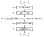
本実施形態の概略の動作は図9に示すようになる。最初のステップS41において、制御回路15は、内視鏡2のID発生部33によるIDからCCD29の種別を判定する。
また、ステップS42において、制御回路15は、モード切替スイッチ14によるスイッチ操作に応じて設定(選択)されている観察モードを把握する。
ステップS43において、制御回路15は、CCD29の種別と観察モードを元にテーブル15cを参照して、第3マトリクス回路49のマトリクスMat3を設定する。
ステップS44において、第3マトリクス回路49は、マトリクスMat3を用いてマトリクス演算を行い、モニタ5に表示する内視鏡画像の画像信号を生成する。そして、ステップS45に示すようにこの内視鏡画像がモニタ5に表示される。
また、ステップS42において、制御回路15は、モード切替スイッチ14によるスイッチ操作に応じて設定(選択)されている観察モードを把握する。
ステップS43において、制御回路15は、CCD29の種別と観察モードを元にテーブル15cを参照して、第3マトリクス回路49のマトリクスMat3を設定する。
ステップS44において、第3マトリクス回路49は、マトリクスMat3を用いてマトリクス演算を行い、モニタ5に表示する内視鏡画像の画像信号を生成する。そして、ステップS45に示すようにこの内視鏡画像がモニタ5に表示される。
本実施形態によれば、照明系から撮像系に至る各種の分光特性の分光積の積分比に応じて第3マトリクス回路49のマトリクスMat3を設定してマトリクス演算を行うようにしている。
従って、内視鏡装置として使用する内視鏡2に搭載されているCCD29、光源装置3、ライトガイド13等の分光特性が異なるような場合においても、それらの分光特性に応じた色分離を輝度信号Yhに対して施すようにしている。従って、色分離の機能が向上し、コントラストの低下を防止できる。
なお、上述の説明においては、CCD29の種別を判定(検知)し、さらに観察モードを参照してテーブル15cから第3マトリクス回路49のマトリクスMat3のマトリクス係数を設定する場合で説明した。本実施形態の変形例として、各内視鏡2にその内視鏡2に搭載されたCCD29と観察モード毎のマトリクスMat3を決定する情報を保持するようにしても良い。
そして、この場合には、制御回路15は、この情報を元にテーブル15cを参照して、対応するマトリクスMat3のマトリクス係数を決定する。そして、第3マトリクス回路49は、そのマトリクスMat3を用いてマトリクス演算を行う。
なお、マトリクスMat3を決定する情報の具体例として、例えばID発生部33が発生するIDを構成する複数ビット部分がこの情報を含む場合で説明する。つまり、IDにおける所定の複数ビットがマトリクスMat3のマトリクス係数を決定する情報を含むとする。
この変形例の場合の概略の動作は、図10に示すようになる。
なお、マトリクスMat3を決定する情報の具体例として、例えばID発生部33が発生するIDを構成する複数ビット部分がこの情報を含む場合で説明する。つまり、IDにおける所定の複数ビットがマトリクスMat3のマトリクス係数を決定する情報を含むとする。
この変形例の場合の概略の動作は、図10に示すようになる。
最初のステップS51において、制御回路15は、モード切替スイッチ14によるスイッチ操作に応じて設定(選択)されている観察モードを把握する。
次のステップS52において内視鏡2のID発生部33は、ビデオプロセッサ4の制御回路15にマトリクスMat3を決定する情報を含むIDを出力する。
また、ステップS53において、制御回路15は、このIDから観察モード毎のマトリクスMat3のマトリクス係数を決める複数ビットのデータを抽出する。
そして、ステップS54において、制御回路15は、現在の観察モードに対応した複数ビットのデータを元にテーブル15cを参照して第3マトリクス回路49のマトリクスMat3を設定する。
次のステップS52において内視鏡2のID発生部33は、ビデオプロセッサ4の制御回路15にマトリクスMat3を決定する情報を含むIDを出力する。
また、ステップS53において、制御回路15は、このIDから観察モード毎のマトリクスMat3のマトリクス係数を決める複数ビットのデータを抽出する。
そして、ステップS54において、制御回路15は、現在の観察モードに対応した複数ビットのデータを元にテーブル15cを参照して第3マトリクス回路49のマトリクスMat3を設定する。
次のステップS55において、第3マトリクス回路49は、マトリクスMat3を用いてマトリクス演算を行い、モニタ5に表示する内視鏡画像の画像信号を生成する。そして、ステップS56に示すようにこの内視鏡画像がモニタ5に表示される。
本変形例は上記第3の実施形態にとほぼ同様の作用効果を有する。
なお、上述した実施形態等を部分的に組み合わせる等して構成される実施形態も本発明に属する。また、上述した第1ないし第3の実施形態においては、WLIモードとNBIモードの観察モードの場合に関して説明したが、さらに励起光を用いて蛍光観察する蛍光モードによる観察モードに適用しても良い。
例えば、蛍光モードへ切り替えた場合、内視鏡の撮像手段に入射される蛍光の分光特性及び撮像手段における色分離フィルタの特性に応じて、第1マトリクス回路に相当するマトリクス係数を切り替え、また、第3マトリクス回路に相当するマトリクス回路のマトリクス係数も第1マトリクス回路に相当する回路の出力信号の信号強度比に基づいて切り替え、輝度信号Yhに対して色分離処理を施すようにしても良い。
本発明は、上述した実施例に限定されるものではなく、本発明の要旨を変えない範囲において、種々の変更、改変等が可能である。
本出願は、2010年6月24日に日本国に出願された特願2010-144083号を優先権主張の基礎として出願するものであり、上記の開示内容は、本願明細書、請求の範囲に引用されるものである。
Claims (8)
- 体腔内を撮像する撮像手段と、
前記撮像手段により撮像された撮像画像に対して第1輝度信号と第1色差信号とに分離する第1色分離手段と、
前記第1輝度信号及び前記第1色差信号に基づいて第1の3原色信号に変換する第1色変換手段と、
前記第1色変換手段からの出力信号を第2色差信号に変換する第2色変換手段と、
前記第1輝度信号及び前記第2色変換手段からの出力信号を第2の3原色信号に変換する第2色分離手段と、
前記第1色変換手段から出力される前記第1の3原色信号の強度比を算出する信号強度比算出手段と、
を有し、
前記信号強度比算出手段の出力結果に応じて前記第2色分離手段の処理内容を切り替えることを特徴とする内視鏡装置。 - 前記体腔内を照明する照明手段を更に備え、前記照明手段が白色光で照明した状態で前記撮像手段が撮像する場合には、前記第1色変換手段による変換を行うマトリクス係数が前記撮像手段に入射する光の分光特性に応じて切り替えられることを特徴とする請求項1に記載の内視鏡装置。
- 前記体腔内を照明する照明手段を更に備え、前記照明手段が所定の狭帯域波長の照明光で照明した状態で前記撮像手段が撮像する場合には、前記第1色変換手段による変換を行うマトリクス係数が前記撮像手段に入射する光の分光特性に応じて切り替えられることを特徴とする請求項1に記載の内視鏡装置。
- 前記照明手段が所定の狭帯域波長の照明光で照明した状態で前記撮像手段が撮像する場合には、前記信号強度比算出手段の出力結果に応じて前記第2色分離手段による色分離の変換を行うマトリクス係数を切り替え、前記照明手段が白色光で照明した状態で前記撮像手段が撮像する場合には、前記第2色分離手段による色分離の変換を行うマトリクス係数を、固定値に設定することを特徴とする請求項2に記載の内視鏡装置。
- 前記照明手段が所定の狭帯域波長の照明光で照明する場合、前記第2色変換手段による変換を行うマトリクス係数は固定値に設定され、前記第2色分離手段による変換を行うマトリクス係数は切り替えられることを特徴とする請求項3に記載の内視鏡装置。
- 前記信号強度比算出手段は、前記撮像手段によりフィールド又はフレーム毎に前記第1の3原色信号の強度比を算出し、前記第2色分離手段は、前記信号強度比算出手段による強度比の出力結果に応じて前記フィールド又はフレーム毎に色分離の変換を行うマトリクス係数を動的に切り替えることを特徴とする請求項1に記載の内視鏡装置。
- 前記信号強度比算出手段は、所定の基準被写体を撮像する状態において指示されたタイミングにおいて前記第1の3原色信号の強度比を算出し、前記第2色分離手段は、前記タイミングで算出された強度比の出力結果に基づいて色分離の変換を行うマトリクス係数を固定値として使用することを特徴とする請求項1に記載の内視鏡装置。
- 所定の狭帯域波長の照明光のもとで前記撮像手段が撮像する場合には、前記第1色差信号に対する通過帯域を制限するフィルタの通過帯域を、白色光の照明光のもとで前記撮像手段が撮像する場合よりも広帯域に設定することを特徴とする請求項2又は3に記載の内視鏡装置。
Priority Applications (4)
| Application Number | Priority Date | Filing Date | Title |
|---|---|---|---|
| EP11797985.6A EP2548498B8 (en) | 2010-06-24 | 2011-06-07 | Endoscopic device |
| JP2011548502A JP5143293B2 (ja) | 2010-06-24 | 2011-06-07 | 内視鏡装置 |
| CN201180026322.8A CN102917633B (zh) | 2010-06-24 | 2011-06-07 | 内窥镜装置 |
| US13/299,801 US8659648B2 (en) | 2010-06-24 | 2011-11-18 | Endoscope apparatus |
Applications Claiming Priority (2)
| Application Number | Priority Date | Filing Date | Title |
|---|---|---|---|
| JP2010144083 | 2010-06-24 | ||
| JP2010-144083 | 2010-06-24 |
Related Child Applications (1)
| Application Number | Title | Priority Date | Filing Date |
|---|---|---|---|
| US13/299,801 Continuation US8659648B2 (en) | 2010-06-24 | 2011-11-18 | Endoscope apparatus |
Publications (1)
| Publication Number | Publication Date |
|---|---|
| WO2011162099A1 true WO2011162099A1 (ja) | 2011-12-29 |
Family
ID=45371295
Family Applications (1)
| Application Number | Title | Priority Date | Filing Date |
|---|---|---|---|
| PCT/JP2011/063063 WO2011162099A1 (ja) | 2010-06-24 | 2011-06-07 | 内視鏡装置 |
Country Status (5)
| Country | Link |
|---|---|
| US (1) | US8659648B2 (ja) |
| EP (1) | EP2548498B8 (ja) |
| JP (1) | JP5143293B2 (ja) |
| CN (1) | CN102917633B (ja) |
| WO (1) | WO2011162099A1 (ja) |
Cited By (3)
| Publication number | Priority date | Publication date | Assignee | Title |
|---|---|---|---|---|
| JP5498626B1 (ja) * | 2012-05-01 | 2014-05-21 | オリンパスメディカルシステムズ株式会社 | 内視鏡装置 |
| WO2016084257A1 (ja) * | 2014-11-28 | 2016-06-02 | オリンパス株式会社 | 内視鏡装置 |
| JP2016214941A (ja) * | 2016-09-12 | 2016-12-22 | 富士フイルム株式会社 | 内視鏡システム及びその作動方法 |
Families Citing this family (8)
| Publication number | Priority date | Publication date | Assignee | Title |
|---|---|---|---|---|
| WO2014156937A1 (ja) * | 2013-03-27 | 2014-10-02 | 富士フイルム株式会社 | 画像処理装置及び内視鏡システムの作動方法 |
| JP6008812B2 (ja) * | 2013-09-27 | 2016-10-19 | 富士フイルム株式会社 | 内視鏡システム及びその作動方法 |
| CN106132279B (zh) * | 2014-06-02 | 2018-08-28 | 奥林巴斯株式会社 | 内窥镜系统 |
| JP6401800B2 (ja) * | 2015-01-20 | 2018-10-10 | オリンパス株式会社 | 画像処理装置、画像処理装置の作動方法、画像処理装置の作動プログラムおよび内視鏡装置 |
| EP3114985A4 (en) * | 2015-03-17 | 2017-12-20 | Olympus Corporation | Endoscope device |
| JP2016193107A (ja) * | 2015-04-01 | 2016-11-17 | Hoya株式会社 | 画像処理装置 |
| CN106725275A (zh) * | 2017-01-13 | 2017-05-31 | 上海市第五人民医院 | 一种用于检查直肠‑肛管黏膜病灶组织的装置 |
| US20210275000A1 (en) * | 2020-03-05 | 2021-09-09 | Stryker Corporation | Systems and methods for endoscope type detection |
Citations (5)
| Publication number | Priority date | Publication date | Assignee | Title |
|---|---|---|---|---|
| JP2000209605A (ja) * | 1999-01-18 | 2000-07-28 | Olympus Optical Co Ltd | 映像信号処理装置 |
| JP2000221417A (ja) * | 1999-02-04 | 2000-08-11 | Olympus Optical Co Ltd | 内視鏡撮像装置 |
| JP2004321608A (ja) * | 2003-04-25 | 2004-11-18 | Olympus Corp | 内視鏡システム |
| JP2007300972A (ja) | 2006-05-08 | 2007-11-22 | Olympus Medical Systems Corp | 内視鏡用画像処理装置 |
| JP2008036035A (ja) * | 2006-08-03 | 2008-02-21 | Olympus Medical Systems Corp | 内視鏡装置 |
Family Cites Families (6)
| Publication number | Priority date | Publication date | Assignee | Title |
|---|---|---|---|---|
| JP4139276B2 (ja) * | 2003-06-17 | 2008-08-27 | オリンパス株式会社 | 電子内視鏡装置及び信号処理装置 |
| JP2005006856A (ja) * | 2003-06-18 | 2005-01-13 | Olympus Corp | 内視鏡装置 |
| JP3813961B2 (ja) * | 2004-02-04 | 2006-08-23 | オリンパス株式会社 | 内視鏡用信号処理装置 |
| US7850599B2 (en) * | 2005-03-04 | 2010-12-14 | Fujinon Corporation | Endoscope apparatus |
| JP4734074B2 (ja) * | 2005-09-30 | 2011-07-27 | オリンパスメディカルシステムズ株式会社 | 内視鏡装置 |
| JP4891990B2 (ja) * | 2006-04-12 | 2012-03-07 | オリンパスメディカルシステムズ株式会社 | 内視鏡装置 |
-
2011
- 2011-06-07 JP JP2011548502A patent/JP5143293B2/ja active Active
- 2011-06-07 CN CN201180026322.8A patent/CN102917633B/zh active Active
- 2011-06-07 EP EP11797985.6A patent/EP2548498B8/en active Active
- 2011-06-07 WO PCT/JP2011/063063 patent/WO2011162099A1/ja active Application Filing
- 2011-11-18 US US13/299,801 patent/US8659648B2/en active Active
Patent Citations (5)
| Publication number | Priority date | Publication date | Assignee | Title |
|---|---|---|---|---|
| JP2000209605A (ja) * | 1999-01-18 | 2000-07-28 | Olympus Optical Co Ltd | 映像信号処理装置 |
| JP2000221417A (ja) * | 1999-02-04 | 2000-08-11 | Olympus Optical Co Ltd | 内視鏡撮像装置 |
| JP2004321608A (ja) * | 2003-04-25 | 2004-11-18 | Olympus Corp | 内視鏡システム |
| JP2007300972A (ja) | 2006-05-08 | 2007-11-22 | Olympus Medical Systems Corp | 内視鏡用画像処理装置 |
| JP2008036035A (ja) * | 2006-08-03 | 2008-02-21 | Olympus Medical Systems Corp | 内視鏡装置 |
Non-Patent Citations (1)
| Title |
|---|
| See also references of EP2548498A4 |
Cited By (7)
| Publication number | Priority date | Publication date | Assignee | Title |
|---|---|---|---|---|
| JP5498626B1 (ja) * | 2012-05-01 | 2014-05-21 | オリンパスメディカルシステムズ株式会社 | 内視鏡装置 |
| CN103987309A (zh) * | 2012-05-01 | 2014-08-13 | 奥林巴斯医疗株式会社 | 内窥镜装置 |
| EP2769665A1 (en) * | 2012-05-01 | 2014-08-27 | Olympus Medical Systems Corp. | Endoscope device |
| EP2769665A4 (en) * | 2012-05-01 | 2015-08-26 | Olympus Medical Systems Corp | ENDOSCOPE DEVICE |
| US9265406B2 (en) | 2012-05-01 | 2016-02-23 | Olympus Corporation | Endoscope apparatus |
| WO2016084257A1 (ja) * | 2014-11-28 | 2016-06-02 | オリンパス株式会社 | 内視鏡装置 |
| JP2016214941A (ja) * | 2016-09-12 | 2016-12-22 | 富士フイルム株式会社 | 内視鏡システム及びその作動方法 |
Also Published As
| Publication number | Publication date |
|---|---|
| US20120127293A1 (en) | 2012-05-24 |
| EP2548498A1 (en) | 2013-01-23 |
| JPWO2011162099A1 (ja) | 2013-08-19 |
| JP5143293B2 (ja) | 2013-02-13 |
| CN102917633B (zh) | 2015-03-11 |
| CN102917633A (zh) | 2013-02-06 |
| EP2548498B8 (en) | 2015-12-23 |
| US8659648B2 (en) | 2014-02-25 |
| EP2548498B1 (en) | 2015-10-14 |
| EP2548498A4 (en) | 2013-07-24 |
Similar Documents
| Publication | Publication Date | Title |
|---|---|---|
| JP5143293B2 (ja) | 内視鏡装置 | |
| JP4996773B2 (ja) | 内視鏡装置 | |
| JP4009626B2 (ja) | 内視鏡用映像信号処理装置 | |
| JP4891990B2 (ja) | 内視鏡装置 | |
| US8773522B2 (en) | Endoscope apparatus | |
| US8500632B2 (en) | Endoscope and endoscope apparatus | |
| KR101015006B1 (ko) | 내시경 장치 | |
| JP5654167B1 (ja) | 内視鏡システム及びその作動方法 | |
| JP5363680B2 (ja) | 医療機器 | |
| JP5308815B2 (ja) | 生体観測システム | |
| WO2014125724A1 (ja) | 内視鏡装置 | |
| JP5041936B2 (ja) | 生体観測装置 | |
| JP3958761B2 (ja) | 内視鏡用調光信号生成装置 |
Legal Events
| Date | Code | Title | Description |
|---|---|---|---|
| WWE | Wipo information: entry into national phase |
Ref document number: 201180026322.8 Country of ref document: CN |
|
| WWE | Wipo information: entry into national phase |
Ref document number: 2011548502 Country of ref document: JP |
|
| 121 | Ep: the epo has been informed by wipo that ep was designated in this application |
Ref document number: 11797985 Country of ref document: EP Kind code of ref document: A1 |
|
| WWE | Wipo information: entry into national phase |
Ref document number: 2011797985 Country of ref document: EP |
|
| NENP | Non-entry into the national phase |
Ref country code: DE |