WO2011162099A1 - Dispositif d'endoscope - Google Patents
Dispositif d'endoscope Download PDFInfo
- Publication number
- WO2011162099A1 WO2011162099A1 PCT/JP2011/063063 JP2011063063W WO2011162099A1 WO 2011162099 A1 WO2011162099 A1 WO 2011162099A1 JP 2011063063 W JP2011063063 W JP 2011063063W WO 2011162099 A1 WO2011162099 A1 WO 2011162099A1
- Authority
- WO
- WIPO (PCT)
- Prior art keywords
- signal
- color
- matrix
- unit
- intensity ratio
- Prior art date
Links
- 239000011159 matrix material Substances 0.000 claims abstract description 153
- 238000000926 separation method Methods 0.000 claims abstract description 57
- 238000005286 illumination Methods 0.000 claims description 54
- 238000006243 chemical reaction Methods 0.000 claims description 45
- 238000003384 imaging method Methods 0.000 claims description 40
- 238000012545 processing Methods 0.000 claims description 30
- 230000003595 spectral effect Effects 0.000 claims description 17
- 101100495256 Caenorhabditis elegans mat-3 gene Proteins 0.000 description 32
- 230000000875 corresponding effect Effects 0.000 description 14
- 230000003287 optical effect Effects 0.000 description 9
- 210000001519 tissue Anatomy 0.000 description 9
- 238000000034 method Methods 0.000 description 8
- 230000008569 process Effects 0.000 description 8
- 230000005540 biological transmission Effects 0.000 description 7
- 230000008859 change Effects 0.000 description 7
- 210000004204 blood vessel Anatomy 0.000 description 6
- 230000006870 function Effects 0.000 description 6
- 238000003780 insertion Methods 0.000 description 6
- 230000037431 insertion Effects 0.000 description 6
- 230000004048 modification Effects 0.000 description 6
- 238000012986 modification Methods 0.000 description 6
- 230000000295 complement effect Effects 0.000 description 4
- 230000009467 reduction Effects 0.000 description 4
- 101100491335 Caenorhabditis elegans mat-2 gene Proteins 0.000 description 3
- 238000010586 diagram Methods 0.000 description 3
- 238000001839 endoscopy Methods 0.000 description 3
- 230000010354 integration Effects 0.000 description 3
- 230000035945 sensitivity Effects 0.000 description 3
- 238000012937 correction Methods 0.000 description 2
- 238000001514 detection method Methods 0.000 description 2
- 230000000694 effects Effects 0.000 description 2
- 230000007246 mechanism Effects 0.000 description 2
- 210000004400 mucous membrane Anatomy 0.000 description 2
- 239000002344 surface layer Substances 0.000 description 2
- 230000002902 bimodal effect Effects 0.000 description 1
- 239000003086 colorant Substances 0.000 description 1
- 230000002596 correlated effect Effects 0.000 description 1
- 230000005284 excitation Effects 0.000 description 1
- 239000000284 extract Substances 0.000 description 1
- 230000035876 healing Effects 0.000 description 1
- 230000003902 lesion Effects 0.000 description 1
- 239000000203 mixture Substances 0.000 description 1
- 238000005070 sampling Methods 0.000 description 1
- 238000001228 spectrum Methods 0.000 description 1
- 230000001360 synchronised effect Effects 0.000 description 1
Images


Classifications
-
- A—HUMAN NECESSITIES
- A61—MEDICAL OR VETERINARY SCIENCE; HYGIENE
- A61B—DIAGNOSIS; SURGERY; IDENTIFICATION
- A61B1/00—Instruments for performing medical examinations of the interior of cavities or tubes of the body by visual or photographical inspection, e.g. endoscopes; Illuminating arrangements therefor
- A61B1/00002—Operational features of endoscopes
- A61B1/00004—Operational features of endoscopes characterised by electronic signal processing
- A61B1/00009—Operational features of endoscopes characterised by electronic signal processing of image signals during a use of endoscope
-
- A—HUMAN NECESSITIES
- A61—MEDICAL OR VETERINARY SCIENCE; HYGIENE
- A61B—DIAGNOSIS; SURGERY; IDENTIFICATION
- A61B1/00—Instruments for performing medical examinations of the interior of cavities or tubes of the body by visual or photographical inspection, e.g. endoscopes; Illuminating arrangements therefor
- A61B1/00002—Operational features of endoscopes
- A61B1/00059—Operational features of endoscopes provided with identification means for the endoscope
-
- A—HUMAN NECESSITIES
- A61—MEDICAL OR VETERINARY SCIENCE; HYGIENE
- A61B—DIAGNOSIS; SURGERY; IDENTIFICATION
- A61B1/00—Instruments for performing medical examinations of the interior of cavities or tubes of the body by visual or photographical inspection, e.g. endoscopes; Illuminating arrangements therefor
- A61B1/00163—Optical arrangements
- A61B1/00186—Optical arrangements with imaging filters
-
- A—HUMAN NECESSITIES
- A61—MEDICAL OR VETERINARY SCIENCE; HYGIENE
- A61B—DIAGNOSIS; SURGERY; IDENTIFICATION
- A61B1/00—Instruments for performing medical examinations of the interior of cavities or tubes of the body by visual or photographical inspection, e.g. endoscopes; Illuminating arrangements therefor
- A61B1/06—Instruments for performing medical examinations of the interior of cavities or tubes of the body by visual or photographical inspection, e.g. endoscopes; Illuminating arrangements therefor with illuminating arrangements
- A61B1/07—Instruments for performing medical examinations of the interior of cavities or tubes of the body by visual or photographical inspection, e.g. endoscopes; Illuminating arrangements therefor with illuminating arrangements using light-conductive means, e.g. optical fibres
-
- H—ELECTRICITY
- H04—ELECTRIC COMMUNICATION TECHNIQUE
- H04N—PICTORIAL COMMUNICATION, e.g. TELEVISION
- H04N23/00—Cameras or camera modules comprising electronic image sensors; Control thereof
- H04N23/50—Constructional details
- H04N23/555—Constructional details for picking-up images in sites, inaccessible due to their dimensions or hazardous conditions, e.g. endoscopes or borescopes
-
- H—ELECTRICITY
- H04—ELECTRIC COMMUNICATION TECHNIQUE
- H04N—PICTORIAL COMMUNICATION, e.g. TELEVISION
- H04N23/00—Cameras or camera modules comprising electronic image sensors; Control thereof
- H04N23/80—Camera processing pipelines; Components thereof
- H04N23/84—Camera processing pipelines; Components thereof for processing colour signals
- H04N23/85—Camera processing pipelines; Components thereof for processing colour signals for matrixing
-
- H—ELECTRICITY
- H04—ELECTRIC COMMUNICATION TECHNIQUE
- H04N—PICTORIAL COMMUNICATION, e.g. TELEVISION
- H04N25/00—Circuitry of solid-state image sensors [SSIS]; Control thereof
- H04N25/10—Circuitry of solid-state image sensors [SSIS]; Control thereof for transforming different wavelengths into image signals
- H04N25/11—Arrangement of colour filter arrays [CFA]; Filter mosaics
- H04N25/13—Arrangement of colour filter arrays [CFA]; Filter mosaics characterised by the spectral characteristics of the filter elements
- H04N25/135—Arrangement of colour filter arrays [CFA]; Filter mosaics characterised by the spectral characteristics of the filter elements based on four or more different wavelength filter elements
- H04N25/136—Arrangement of colour filter arrays [CFA]; Filter mosaics characterised by the spectral characteristics of the filter elements based on four or more different wavelength filter elements using complementary colours
-
- H—ELECTRICITY
- H04—ELECTRIC COMMUNICATION TECHNIQUE
- H04N—PICTORIAL COMMUNICATION, e.g. TELEVISION
- H04N9/00—Details of colour television systems
- H04N9/64—Circuits for processing colour signals
- H04N9/67—Circuits for processing colour signals for matrixing
-
- A—HUMAN NECESSITIES
- A61—MEDICAL OR VETERINARY SCIENCE; HYGIENE
- A61B—DIAGNOSIS; SURGERY; IDENTIFICATION
- A61B1/00—Instruments for performing medical examinations of the interior of cavities or tubes of the body by visual or photographical inspection, e.g. endoscopes; Illuminating arrangements therefor
- A61B1/04—Instruments for performing medical examinations of the interior of cavities or tubes of the body by visual or photographical inspection, e.g. endoscopes; Illuminating arrangements therefor combined with photographic or television appliances
- A61B1/05—Instruments for performing medical examinations of the interior of cavities or tubes of the body by visual or photographical inspection, e.g. endoscopes; Illuminating arrangements therefor combined with photographic or television appliances characterised by the image sensor, e.g. camera, being in the distal end portion
Definitions
- the present invention relates to an endoscope apparatus that performs signal processing on imaging means provided in an endoscope and generates an endoscope image.
- the luminance signal Y1 is generated by passing the luminance signal Y through the low-pass filter, and the luminance signal Yh not passing through the low-pass filter.
- the luminance signal Yh and the second matrix circuit 46 are output in conjunction with switching of the observation mode between normal white light observation (WLI) and narrow band light observation (NBI).
- WLI normal white light observation
- NBI narrow band light observation
- the luminance signal Ynbi in the NBI observation mode is switched by the selector 39 and output to the subsequent stage side.
- the luminance signal Yh in the observation mode of the WLI is subjected to signal processing at the subsequent stage while being separated from the luminance signal Y as the output signal of the second matrix circuit 46, so that color separation is sufficiently performed. Absent.
- the operator may set the NBI observation mode in order to observe the blood vessel image and the mucous membrane fine structure in detail.
- the luminance signal Yh is output to the display means as an image signal in a state independent of the color signal image signal in NBI. For this reason, it causes a decrease in contrast of the blood vessel image and the mucous membrane microstructure.
- the present invention has been made in view of the above-described points, and an object of the present invention is to provide an endoscope apparatus that can generate an endoscopic image with little reduction in contrast by improving color separation.
- An endoscope apparatus includes an imaging unit that images a body cavity, and a first color separation that separates a captured image captured by the imaging unit into a first luminance signal and a first color difference signal.
- Means a first color conversion means for converting the first luminance signal and the first color difference signal into a first three primary color signal, and an output signal from the first color conversion means for converting to a second color difference signal.
- Signal intensity ratio calculating means for calculating the intensity ratio of the first three primary color signals, and switching the processing contents of the second color separating means in accordance with the output result of the signal intensity ratio calculating means.
- the block diagram which shows the structure of the endoscope apparatus of the 3rd Embodiment of this invention. 10 is a flowchart for explaining main operations in the third embodiment.
- an endoscope apparatus 1 includes an electronic endoscope (hereinafter simply referred to as an endoscope) 2 that is inserted into a body cavity and performs an endoscopic examination, A light source device 3 for supplying illumination light to the endoscope 2.
- the endoscope apparatus 1 drives an imaging means built in the endoscope 2 and also performs a video processor 4 as an endoscope video signal processing apparatus that performs signal processing on an output signal of the imaging means, A monitor 5 that displays an image obtained by performing signal processing on the captured image captured by the imaging unit as an endoscopic image when the video signal output from the video processor 4 is input.
- the endoscope 2 includes an elongated insertion portion 7, an operation portion 8 provided at the rear end of the insertion portion 7, and a universal cable 9 extending from the operation portion 8.
- the light guide connector 11 at the end of this is detachably connected to the light source device 3, and the signal connector is detachably connected to the video processor 4.
- a light guide 13 that transmits illumination light is inserted into the insertion portion 7, and the light guide connector 11 at the end on the hand side of the light guide 13 is connected to the light source device 3.
- Illumination light is supplied to the light guide 13.
- the light source device 3 In the normal white light observation (WLI) mode, the light source device 3 generates white illumination light that covers the visible wavelength region as illumination light and supplies it to the light guide 13.
- WLI normal white light observation
- narrow-band illumination light is generated as illumination light and supplied to the light guide 13.
- the switching instruction between the WLI mode and the NBI mode can be performed by, for example, the mode switch 14 such as a scope switch provided in the operation unit 8 of the endoscope 2.
- the mode change switch 14 may be constituted by a foot switch, or a mode change switch may be provided on the front panel of the video processor 4. You may comprise with the keyboard which is not illustrated.
- the switching signal from the mode switch 14 is input to the control circuit 15 in the video processor 4. When the switching signal is input, the control circuit 15 controls the filter insertion / removal mechanism 16 of the light source device 3 to perform normal operation. Selectively switch between white light and narrowband illumination light.
- control circuit 15 also performs control for switching characteristics of the signal processing system in the video processor 4 in conjunction with switching control of illumination light supplied from the light source device 3 to the light guide 13. Then, by switching the characteristics of the signal processing system by the switching operation by the mode selector switch 14, signal processing suitable for each observation mode of the WLI mode and the NBI mode can be performed.
- the light source device 3 incorporates a lamp 20 that generates illumination light, and the lamp 20 generates illumination light including a visible wavelength region.
- the illumination light is incident on the diaphragm 22 after the infrared light is cut by the infrared cut filter 21 so that the illumination light is close to the wavelength band of substantially white light.
- the aperture of the diaphragm 22 is adjusted by a diaphragm driving circuit 23 and the amount of light passing therethrough is controlled.
- the illumination light that has passed through the diaphragm 22 passes through the narrow band filter 24 inserted into and removed from the illumination optical path by the filter insertion / removal mechanism 16 constituted by a plunger or the like, or does not pass through the narrow band filter 24 in the NBI mode.
- the light is condensed by the condensing lens 25 and is incident on the hand side end face of the light guide 13, that is, the incident end face.
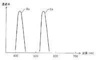
- FIG. 2 shows an example of the spectral characteristics of the narrowband filter 24.
- the narrowband filter 24 exhibits bimodal filter characteristics, and has narrowband transmission filter characteristics portions Ga and Ba, for example, in each of the green and blue wavelength regions. More specifically, the narrow band transmission filter characteristic portions Ga and Ba have bandpass characteristics with center wavelengths of 540 nm and 420 nm, respectively, and a half width of 20 to 40 nm.
- the narrow band filter 24 when the narrow band filter 24 is disposed in the illumination optical path, the two bands of narrow band illumination light that has passed through the narrow band transmission filter characteristic portions Ga and Ba are incident on the light guide 13.
- broadband white light is supplied to the light guide 13. Illumination light from the light guide 13 is transmitted to the distal end surface by the light guide 13, and is emitted to the outside through an illumination lens 27 that constitutes illumination means attached to an illumination window provided at the distal end portion 26 of the insertion portion 7. Illuminates the surface of a living tissue such as an affected part in a body cavity.
- the distal end portion 26 is provided with an observation window adjacent to the illumination window, and an objective lens 28 is attached to the observation window.
- the objective lens 28 forms an optical image by reflected light from the living tissue.
- a charge-coupled device (abbreviated as CCD) 29 is disposed at the image forming position of the objective lens 28 as a solid-state imaging device constituting the imaging means, and photoelectric conversion is performed by the CCD 29.
- a complementary color filter shown in FIG. 3 is attached to the image pickup surface of the CCD 29 for each pixel as a color separation filter 30 for optically color separation.
- This complementary color filter has four color chips of magenta (Mg), green (G), cyan (Cy), and yellow (Ye) in front of each pixel. Alternatingly arranged in the vertical direction, Mg, Cy, Mg, Ye and G, Ye, G, Cy are arranged in the order of arrangement.
- the signal read from the CCD 29 generates a luminance signal and a color difference signal by a Y / C separation circuit 37 (as a first color separation means) on the subsequent stage side as is well known.
- the CCD 29 is connected to one end of a signal line. By connecting a signal connector to which the other end of the signal line is connected to the video processor 4, the CCD driving circuit 31 and the CDS circuit 32 in the video processor 4 are connected. Connected to.
- Each endoscope 2 includes an ID generation unit 33 that generates identification information (ID) unique to the endoscope 2, and the ID generated by the ID generation unit 33 is input to the control circuit 15, and the control circuit 15 Identifies the type of endoscope 2 connected to the video processor 4 and the number and types of pixels of the CCD 29 built in the endoscope 2 by ID.
- ID identification information
- the control circuit 15 controls the CCD drive circuit 31 so as to appropriately drive the identified CCD 29 of the endoscope 2.
- the CCD 29 receives the CCD drive signal from the CCD drive circuit 31 and inputs the photoelectrically converted imaging signal to a correlated double sampling circuit (abbreviated as CDS circuit) 32.
- CDS circuit correlated double sampling circuit
- a signal component is extracted from the imaging signal by the CDS circuit 32 and converted into a baseband signal, which is then input to the A / D conversion circuit 34, converted into a digital signal, and input to the brightness detection circuit 35. , Brightness (average luminance of the signal) is detected.
- the brightness signal detected by the brightness detection circuit 35 is input to the dimming circuit 36, and a dimming signal for dimming is generated based on the difference from the reference brightness (target dimming value).
- the dimming signal from the dimming circuit 36 is input to the aperture driving circuit 23, and the aperture driving circuit 23 adjusts the opening amount of the aperture 22 so that the reference brightness is obtained.
- the digital signal output from the A / D conversion circuit 34 is input to the Y / C separation circuit 37.
- the Y / C separation circuit 37 detects the luminance signal Y and the line-sequential color difference (as the color signal C in a broad sense). Signals Cr and Cb are generated.
- the Y / C separation circuit 37 forms a first color separation means. Therefore, the luminance signal Y as the output signal of the Y / C separation circuit 37 is the first luminance signal, and the color difference signals Cr and Cb are the first color difference. Corresponds to the signal.
- the luminance signal Y is input to the enlargement circuit 47 via the ⁇ circuit 38 (this luminance signal is referred to as Yh) and is also input to a first low-pass filter (abbreviated as LPF) 41a that restricts the pass band of the signal.
- LPF 41a is set to a wide pass band corresponding to the luminance signal Y, and the luminance signal Yl of the band set by the pass band characteristic of the LPF 41a is sent to the first matrix circuit 42 as the first color conversion means. Entered.
- the color difference signals Cr and Cb are input to the synchronization circuit 43 (line-sequentially) via the second LPF 41b that limits the passband of the signal.
- the characteristics of the pass band of the second LPF 41b are changed by the control circuit 15 in accordance with the observation mode.
- the second LPF 41b is set to a lower band than the first LPF 41a. That is, in the WLI mode, it is set to perform signal processing conforming to standard video signal standards.
- the second LPF 41b is changed to a band wider than the low band in the WLI mode.
- the second LPF 41b is set (changed) in a wide band in substantially the same manner as the first LPF 41a.
- the second LPF 41b forms processing characteristic changing means for changing the processing characteristic for limiting the pass band for the color difference signals Cr and Cb in conjunction with the switching of the observation mode.
- the band characteristics of the signal passage of the second LPF 41b are widened, so that the G color signal imaged under the G illumination light that is close to the luminance state signal of the traveling state of the capillary blood vessels and the narrow band transmission filter characteristic section Ga.
- the resolution (resolution) of the blood vessel running state near the surface layer obtained by the above can be improved, and an image with good image quality that is easy to diagnose can be obtained.
- the synchronization circuit 43 generates the synchronized color difference signals Cr and Cb, and the color difference signals Cr and Cb are input to the first matrix circuit 42 as the first color conversion means.
- the first matrix circuit 42 converts the luminance signal Yl and the color difference signals Cr and Cb into the first three primary color signals R1, G1, and B1, and outputs them to the signal intensity ratio calculation circuit 44 that calculates the signal intensity ratio.
- the first three primary color signals R1, G1, and B1 are also input to a ⁇ circuit 45 that performs gamma correction.
- the first matrix circuit 42 is controlled by the control circuit 15 and changes (switches) the value of the matrix coefficient according to the characteristics of the color separation filter 30 of the CCD 29 and the characteristics of the narrowband filter 24 (determining conversion characteristics). To do. That is, the first matrix circuit 42 changes the value of the matrix coefficient to be converted into the first three primary color signals R1, G1, and B1 in accordance with the spectral characteristics of the light incident on the CCD 29 as the imaging means. Then, the first matrix circuit 42 converts the signals into three primary color signals R1, G1, and B1 that have no color mixing or almost eliminate color mixing. Note that, as described above, in the NBI mode, illumination light in the red wavelength band is not used, and thus there is no R1 color signal.
- the characteristics of the color separation filter 30 of the CCD 29 mounted on the endoscope 2 may differ depending on the endoscope 2 that is actually connected to the video processor 4.
- the matrix coefficients to be converted into the first three primary color signals R1, G1, and B1 by the first matrix circuit 42 are changed according to the characteristics of the color separation filter 30 of the CCD 29 that is actually used.
- the signal intensity ratio calculation circuit 44 calculates the signal intensity ratios s, t, u of the three primary color signals R1, G1, B1 input through the first matrix circuit 42, and the calculated signal intensity ratios s, t, Information on u is output to the control circuit 15. Therefore, the signal intensity ratio calculation circuit 44 integrates the signal levels of the first three primary color signals R1, G1, and B1 output from the first matrix circuit 42 for each field unit, and 3 based on the integration result.
- the signal intensity ratios s, t, u of the primary color signals R1, G1, B1 are calculated.
- the signal intensity ratios s, t, and u are calculated by integration within a predetermined region Rd set in an image region Ro of one field.
- the signal intensity ratio calculation circuit 44 may be provided inside the control circuit 15, for example.
- the signal intensity ratios s, t, u of the three primary color signals R1, G1, B1 are calculated for each field unit, and the third matrix circuit 49 constituting the second color separation means as will be described later.
- the matrix coefficient is dynamically changed on a field basis.
- the control circuit 15 includes a reference table 15 a that is referred to for setting matrix coefficients by the first matrix circuit 42, the second matrix circuit 46, and the third matrix circuit 49.
- the ⁇ circuit 45 is also controlled by the control circuit 15. Specifically, in the NBI mode, the ⁇ characteristics are changed to emphasize the ⁇ correction characteristics than in the WLI mode. As a result, the contrast on the low signal level side is enhanced, and the display characteristics are more easily identified.
- the three primary color signals R2, G2, and B2 that have been ⁇ -corrected by the ⁇ circuit 45 are input to the second matrix circuit 46 that constitutes the second color conversion means, and the second matrix circuit 46 causes the color difference as follows. Converted to signals RY and BY.
- the matrix Mat2 is expressed as, for example, the expression (3). [Equation 1]
- the second matrix circuit 46 employs, for example, a matrix coefficient fixed to a fixed value regardless of switching of the observation mode.
- the color difference signals RY and BY output from the second matrix circuit 46 are input together with the luminance signal Yh to an enlargement circuit 47 that performs enlargement processing.
- the luminance signal Yh enlarged by the enlargement circuit 47 is subjected to edge enhancement by the enhancement circuit 48, and then input to the third matrix circuit 49, and the color difference signals RY and BY enlarged by the enlargement circuit 47. Is input to the third matrix circuit 49 without passing through the emphasis circuit 48.
- the luminance signal Yh and the color difference signals RY and BY are converted into the three primary color signals R, G, and B by the third matrix circuit 49 as the second color separation means.
- the three primary color signals R, G, and B are converted into analog video signals by a D / A conversion circuit (not shown) and output to the monitor 5 from the video signal output terminal.
- the matrix Mat3 (matrix coefficient thereof) is based on the signal intensity ratios s, t, u of the first three primary color signals R1, G1, B1 generated by the first matrix circuit 42.
- the control circuit 15 can dynamically switch. Specifically, if the matrix of 2 rows and 3 columns of the second matrix circuit 46 is Mat2, and the signal intensity ratios s, t, u of the first three primary color signals R1, G1, B1 are used, the matrix Mat3 is , [Equation 2] It is dynamically switched so that
- the matrix Mat2 is, for example, [Equation 3]. It is set like this.
- () ⁇ 1 means an inverse matrix.
- the NBI mode when the endoscopic image is displayed in color on the monitor 5, it is displayed after color conversion in order to improve the visibility compared with the case of displaying the actual color signal as it is. There is provided a color conversion setting unit 50 for performing setting.
- the surgeon When performing color conversion, the surgeon performs an operation of turning on a color conversion switch (not shown) in the color conversion setting unit 50, and the operation signal is output to the control circuit 15.
- the control circuit 15 uses, for example, a matrix element (also referred to as matrix coefficient) k1 for performing standard color conversion stored in advance in the table 15a. , K2 and k3, instead of using the matrix Mat3 of the formula (2), the matrix Mat3 of the following formula (4) is used. [Equation 4] As apparent from the above expression, the matrix Mat3 in the equation (4) is obtained by multiplying the matrix Mat3 in the equation (2) by the color conversion matrix M Trans including the matrix elements k1, k2, and k3 for color conversion.
- the surgeon may operate the color conversion setting unit 50 to variably set the values of the matrix elements k1, k2, and k3 for color conversion when performing color conversion.
- the edge enhancement by the enhancement circuit 48 is also changed via the control circuit 15 according to the type of the CCD 29, the color separation filter 30 and the like, and the enhancement characteristics (whether the enhancement band is set to the middle or low band). You may do it.
- the luminance signal Yh is emphasized, a process that emphasizes structures such as capillaries near the surface of the living body is performed, and the image component of interest can be clearly displayed.
- the signal intensity ratio s, t, u is calculated.
- the three primary color signals R, G, and B as image signals when an endoscopic image is displayed on the monitor 5 are converted into the third matrix circuit 49.
- the luminance signal Yh and the color difference signals RY and BY are generated according to the color separation processing.
- the luminance signal Yh generated by the Y / C separation circuit 37 is converted into each of the first three primary color signals R1, G1, B1 by matrix calculation using the matrix Mat3 of the third matrix circuit 49. A color separation process reflecting the signal intensity ratio is performed.
- the endoscope apparatus 1 having such a configuration separates a CCD 29 as an imaging unit that images the inside of a body cavity and a first luminance signal and a first color difference signal that are separated from a captured image captured by the imaging unit.
- a Y / C separation circuit 37 as one color separation means, and a first matrix circuit 42 as first color conversion means for converting the first three primary color signals based on the first luminance signal and the first color difference signal;
- the endoscope apparatus 1 includes a second matrix circuit 46 as a second color conversion unit that converts an output signal from the first color conversion unit into a second color difference signal, the first luminance signal, and the second luminance signal.
- step S1 as the operation mode of the light source device 3 and the video processor 4, for example, the WLI mode is set.
- the light source device 3 is set in a state in which the narrowband filter 24 is detached from the illumination optical path as shown by the solid line in FIG. 1, and performs imaging with the endoscope 2 under white illumination light. It becomes a state.
- each unit on the video processor 4 side is also set to perform signal processing in the WLI mode.
- the signal strength ratio calculation circuit 44 in the processor 4 calculates the signal strength ratios s and t for each field.
- the control circuit 15 sets the matrix Mat3 of the third matrix circuit 49 with reference to the table 15a based on the signal intensity ratios s and t.
- the third matrix circuit 49 performs matrix calculation using the matrix Mat3. By this matrix operation, the third matrix circuit 49 generates the three primary color signals R, G, and B in a state where the luminance signal Yh is color-separated according to the signal intensity ratios s, t, and u as shown in step S5. To do.
- step S6 an endoscopic image corresponding to the three primary color signals R, G, B is displayed on the monitor 5.
- the surgeon performs an endoscopic examination on a tissue to be examined such as an affected part in a body cavity while observing the endoscopic image.
- the surgeon operates the mode switch 14.
- step S7 the control circuit 15 monitors whether or not the mode change switch 14 has been operated. If the mode change switch 14 has not been operated, the control circuit 15 returns to step S2 to maintain the WLI mode state. When the changeover switch 14 is operated, the process proceeds to the next step S8.
- step S8 the control circuit 15 changes the operation mode of the light source device 3 and the video processor 4 to the setting state of the NBI mode. Specifically, the control circuit 15 controls the light source device 3 so that the narrowband filter 24 is arranged in the illumination optical path as indicated by a two-dot chain line in FIG. As shown in FIG. 2, the narrow band filter 24 is arranged in the illumination optical path so that the illumination is performed by the narrow band illumination light from the narrow band transmission filter characteristic portions Ga and Ba. In addition, the control circuit 15 changes the setting of each unit in the video processor 4. Specifically, the control circuit 15 widens the band characteristic of the LPF 41b.
- the band characteristics of the signal passing of the LPF 41b are widened, and the G color imaged under the G illumination light that is close to the luminance state signal of the traveling state of the capillary blood vessels and the narrow band transmission filter characteristic unit Ga as described above.
- the resolution (resolution) of the blood vessel running state near the surface layer obtained by the signal is improved.
- the signal strength ratio calculation circuit 44 calculates the signal strength ratio t for each field.
- the third matrix circuit 49 performs a matrix operation using the matrix Mat3. With this matrix operation, the third matrix circuit 49 performs the three primary color signals G, B or R, G, B in a state where the luminance signal Yh is color-separated according to the signal intensity ratios t, u as shown in step S12. Is generated.
- the color conversion setting unit 50 is OFF, the third matrix circuit 49 generates the three primary color signals G and B.
- the color conversion setting unit 50 is ON, the third matrix circuit 49 Three primary color signals R, G, and B are generated.
- an endoscopic image corresponding to the three primary color signals G and B or R, G and B is displayed on the monitor 5.
- the control circuit 15 monitors whether or not the mode change switch 14 has been operated. If the mode change switch 14 has not been operated, the control circuit 15 returns to the process of step S9 and maintains the state of the NBI mode. If the mode switch 14 is operated, the process returns to step S1.
- the mode change switch 14 is operated, the process returns to step S1.
- a narrow band light source device can be easily formed by providing means for inserting / removing the narrow band filter 24 in / from the optical path in addition to the normal white light illumination means.
- the matrix coefficient is changed by the third matrix circuit 49 in accordance with the calculation result of the signal intensity ratio of the signal intensity ratio calculation circuit 44 in both the WLI mode and the NBI mode. I was going.
- the matrix coefficient of the third matrix circuit 49 is changed (switched) in accordance with the calculation result of the signal strength ratio of the signal strength ratio calculation circuit 44, and in the WLI mode.
- the matrix coefficient of the third matrix circuit 49 is different in the signal intensity ratio calculation result of the signal intensity ratio calculation circuit 44, the matrix coefficient may be set to a predetermined fixed value and used at that fixed value.
- the same effect as that of the first embodiment is obtained in the NBI mode.
- the WLI mode even if the matrix coefficient of the third matrix circuit 49 is fixed, the influence of the contrast reduction due to the color separation process on the luminance signal Yh can be reduced as in the NBI mode.
- the signal intensity ratio calculation circuit 44 is set under predetermined conditions (for example, in the case of initial setting or described later). It may be set to a fixed value corresponding to the calculation result of the signal intensity ratio at the time when the white balance instruction is given.
- FIG. 6 shows a configuration of an endoscope apparatus 1B according to the second embodiment of the present invention.
- a WB switch 14b for performing an instruction operation for obtaining white balance (abbreviated as WB) is provided in the endoscope 2, for example.
- WB switch 14b may be provided in the video processor 4. Further, it may be provided in the endoscope 2 and the video processor 4.
- the WB switch 14b is operated by an operator or the like in a state where the endoscope 2 is set in a state where the endoscope 2 images a predetermined reference subject such as a white subject prepared in advance in the WLI mode. Further, even in the NBI mode, the operation is performed in a state where a predetermined reference subject prepared in advance in the NBI mode is illuminated and imaged with narrow-band illumination light.
- a common reference subject may be used in the WLI mode and the NBI mode, or different reference subjects may be used.
- the WB switch 14b sends a WB acquisition instruction signal to the control circuit 15.
- the control circuit 15 acquires information on the signal intensity ratios s, t, u calculated for the first three primary color signals R1, G1, B1 by the signal intensity ratio calculation circuit 44 at the timing when the instruction signal is input. .
- the control circuit 15 sets the matrix coefficient value of the third matrix circuit 49 as a predetermined fixed value using the information of the signal intensity ratio s, t, u (or t, u) acquired at this timing, Thereafter, unless the WB switch 14b is operated, the matrix coefficient value is controlled to be used without being changed. Therefore, in the present embodiment, the signal intensity ratio calculation circuit 44 reflects the information of the signal intensity ratio acquired under the condition for imaging the reference subject on the third matrix circuit 49 (for the luminance signal Yh). It has a function of generating three primary color signals (with color separation).
- control circuit 15 has information on the signal strength ratio s, t, u when the WB switch 14b is operated in the WLI mode and the WB switch 14b is operated in the NBI mode.
- Other configurations are the same as those of the first embodiment.
- FIG. 7 is a flowchart for explaining main operations according to this embodiment.
- the surgeon first makes initial settings. For this reason, a predetermined reference subject is prepared in step S21.
- the predetermined reference subject is set in a state of being imaged by the endoscope 2, is set to the WLI mode, and the WB switch 14b is operated.
- the signal strength ratio calculation circuit 44 calculates the signal strength ratios s and t in the field or frame when the WB switch 14b is operated, and outputs it to the control circuit 15.
- the control circuit 15 stores the values of the signal strength ratios s and t in the memory 15b.
- the control circuit 15 displays on the monitor 5 that the values of the signal strength ratios s and t are stored.
- next step S24 the surgeon operates the mode switch 14 to switch to the NBI mode.
- the operator operates the WB switch 14b in the next step S25.
- step S26 the signal strength ratio calculation circuit 44 calculates the signal strength ratio t in the field or frame when the WB switch 14b is operated, and outputs it to the control circuit 15.
- the control circuit 15 stores the value of the signal strength ratio t in the memory 15b.
- the control circuit 15 displays on the monitor 5 that the value of the signal strength ratio t has been stored. In this way, the initial setting is completed.
- step S28 the control circuit 15 sets the matrix Mat3 with reference to the values of the signal intensity ratios s and t in the WLI mode from the memory 15b and the table 15a.
- step S29 the third matrix circuit 49 performs matrix calculation using the matrix Mat3.
- An endoscopic image is displayed on the monitor 5.
- step S30 the control circuit 15 monitors whether or not the mode switch 14 has been operated. If the mode switch 14 has not been operated, the process returns to step S29, matrix calculation is performed using the same matrix Mat3, and an endoscopic image is displayed on the monitor 5.
- the surgeon further operates the mode changeover switch 14 when he wants to observe the running state of blood vessels on the surface of the tissue to be examined in more detail.
- the light source device 3 and the video processor 4 are set in the NBI mode.
- the LPF 41b is switched to a broadband characteristic.
- the control circuit 15 sets the matrix Mat3 with reference to the information of the signal intensity ratio t in the NBI mode from the memory 15b and the table 15a.
- the third matrix circuit 49 performs a matrix operation using the matrix Mat3. An endoscopic image is displayed on the monitor 5.
- step S33 the control circuit 15 monitors whether or not a mode switching operation has been performed. If the mode switching operation is not performed, the process returns to step S32, and the matrix calculation is performed using the same matrix Mat3. An endoscopic image is displayed on the monitor 5. On the other hand, when the mode switching operation is performed, the process returns to step S27, the WLI mode is set, and the above-described processing is repeated. According to the present embodiment, an endoscopic image corresponding to a case where color separation processing reflecting a signal intensity ratio in a state in which a predetermined reference subject for which the WB switch 14b is operated is imaged is displayed.
- the present embodiment performs color separation processing corresponding to a state in which a predetermined reference subject is imaged, and thus is suitable for a case where the healing state is compared over time with respect to the same lesion portion or the like.
- the present embodiment has a possibility of displaying capillaries and the like of the examination target tissue with higher contrast by selecting and setting a predetermined reference subject in the NBI mode according to the examination target tissue.
- the luminance signal Yh is subjected to color separation processing in the case of the reference subject, and is used for display as an endoscopic image 3. Since the primary color signal is generated, the contrast of the endoscopic image displayed on the monitor 5 can be prevented from being lowered.
- the WLI mode can be selected to operate in the operation mode of the second embodiment
- the NBI mode can be selected to operate in the operation mode of the first embodiment. Also good. It may also be possible to select to operate in the reverse operation mode.
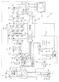
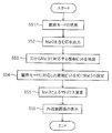
- FIG. 8 shows a configuration of an endoscope apparatus 1C according to the third embodiment of the present invention.
- the endoscope apparatus 1C according to the present embodiment does not include the signal intensity ratio calculation circuit 44 in the endoscope apparatus 1 illustrated in FIG.
- the endoscope apparatus 1C according to the present embodiment uses the matrix coefficients of the first matrix circuit 42 and the third matrix circuit 49 as the spectral sensitivity characteristics of the color separation filter 30 of the CCD 29 mounted on the endoscope 2.
- the light source device 3 or the light guide 13 of the endoscope 2 is switched according to the type, white light or narrow band light emitted from the illumination lens 27, that is, the observation mode.
- the control circuit 15 in the video processor 4 is provided in, for example, the control circuit 15 according to the combination of the determination result of the type of the CCD 29 and the observation mode based on the ID from the ID generation unit 33 of the endoscope 2.
- the matrix Mat3 of the third matrix circuit 49 is set.
- the table 15c stores data for setting a matrix Mat3 (a matrix coefficient) corresponding to the combination of the spectral sensitivity characteristic of the color separation filter 30 of the CCD 29 and the observation mode.
- the matrix of the second matrix circuit 46 is a fixed value.
- the matrix coefficient of the matrix Mat3 is a spectrum as a product of various spectral characteristics from the illumination system to the imaging system in each wavelength band of R, G, B (or G, B) in the luminance signal. Calculated (set) based on the ratio of the integral values of the products.
- the spectral sensitivity characteristics of the CCD 29 mounted on the endoscope 2 used as the endoscope apparatus, the spectral characteristics of the illumination light of the light source apparatus 3, and the illumination light from the light source apparatus 3 are transmitted. Even when the spectral characteristics of the illumination light transmission means of the light guide 13 that is emitted as illumination light from the distal end of the lever to the examination target tissue in the body cavity are different, appropriate color separation is performed for the luminance signal Yh accordingly. To give.
- Other configurations are the same as those of the first embodiment.
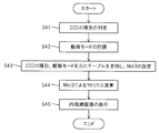
- step S41 the control circuit 15 determines the type of the CCD 29 from the ID by the ID generation unit 33 of the endoscope 2.
- step S ⁇ b> 42 the control circuit 15 grasps the observation mode that is set (selected) according to the switch operation by the mode switch 14.
- step S43 the control circuit 15 sets the matrix Mat3 of the third matrix circuit 49 with reference to the table 15c based on the type of the CCD 29 and the observation mode.
- step S ⁇ b> 44 the third matrix circuit 49 performs matrix calculation using the matrix Mat ⁇ b> 3 and generates an image signal of an endoscopic image to be displayed on the monitor 5. Then, as shown in step S45, this endoscopic image is displayed on the monitor 5.
- matrix calculation is performed by setting the matrix Mat3 of the third matrix circuit 49 according to the integration ratio of spectral products of various spectral characteristics from the illumination system to the imaging system. Therefore, even when the spectral characteristics of the CCD 29, the light source device 3, the light guide 13 and the like mounted on the endoscope 2 used as the endoscope apparatus are different, color separation corresponding to the spectral characteristics is performed with luminance. It is applied to the signal Yh. Accordingly, the function of color separation is improved, and a reduction in contrast can be prevented.
- each endoscope 2 may hold information for determining the CCD 29 mounted on the endoscope 2 and the matrix Mat3 for each observation mode.
- the control circuit 15 determines a matrix coefficient of the corresponding matrix Mat3 with reference to the table 15c based on this information.
- the third matrix circuit 49 performs matrix calculation using the matrix Mat3.
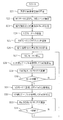
- information for determining the matrix Mat3 a case where a plurality of bits constituting an ID generated by the ID generation unit 33 includes this information will be described. That is, it is assumed that the predetermined plural bits in the ID include information for determining the matrix coefficient of the matrix Mat3.
- the schematic operation in the case of this modification is as shown in FIG.
- the control circuit 15 grasps the observation mode set (selected) according to the switch operation by the mode changeover switch 14.
- the ID generator 33 of the endoscope 2 outputs an ID including information for determining the matrix Mat3 to the control circuit 15 of the video processor 4.
- the control circuit 15 extracts a plurality of bits of data for determining the matrix coefficient of the matrix Mat3 for each observation mode from this ID.
- the control circuit 15 sets the matrix Mat3 of the third matrix circuit 49 with reference to the table 15c based on a plurality of bits of data corresponding to the current observation mode.
- the third matrix circuit 49 performs matrix calculation using the matrix Mat3 and generates an image signal of an endoscopic image to be displayed on the monitor 5. Then, as shown in step S56, this endoscopic image is displayed on the monitor 5.
- This modification has substantially the same function and effect as the third embodiment. Note that embodiments configured by partially combining the above-described embodiments and the like also belong to the present invention.
- the observation mode of the WLI mode and the NBI mode has been described.
- the present invention may be applied to an observation mode by a fluorescence mode in which fluorescence observation is performed using excitation light. .
- the matrix coefficient corresponding to the first matrix circuit is switched according to the spectral characteristics of fluorescence incident on the imaging unit of the endoscope and the characteristics of the color separation filter in the imaging unit
- the matrix coefficient of the matrix circuit corresponding to the third matrix circuit may be switched based on the signal intensity ratio of the output signal of the circuit corresponding to the first matrix circuit, and color separation processing may be performed on the luminance signal Yh.
Landscapes
- Health & Medical Sciences (AREA)
- Life Sciences & Earth Sciences (AREA)
- Engineering & Computer Science (AREA)
- Surgery (AREA)
- Signal Processing (AREA)
- Physics & Mathematics (AREA)
- Heart & Thoracic Surgery (AREA)
- Medical Informatics (AREA)
- Nuclear Medicine, Radiotherapy & Molecular Imaging (AREA)
- Optics & Photonics (AREA)
- Pathology (AREA)
- Radiology & Medical Imaging (AREA)
- Multimedia (AREA)
- Biomedical Technology (AREA)
- Veterinary Medicine (AREA)
- Biophysics (AREA)
- Molecular Biology (AREA)
- Animal Behavior & Ethology (AREA)
- General Health & Medical Sciences (AREA)
- Public Health (AREA)
- Spectroscopy & Molecular Physics (AREA)
- Endoscopes (AREA)
- Instruments For Viewing The Inside Of Hollow Bodies (AREA)
- Closed-Circuit Television Systems (AREA)
Abstract
Dans un dispositif d'endoscope, un signal imagé au moyen d'un dispositif à transfert de charge (DTC) possédant un filtre séparateur de couleurs est séparé à l'aide d'un circuit de séparation Y/C en un premier signal de brillance et un premier signal de différence des couleurs. Ensuite, à l'aide d'un premier et d'un deuxième circuits matriciels, le signal est transformé en un signal des trois couleurs primaires et en un deuxième signal de différence des couleurs et simultanément, à l'aide d'un circuit de calcul du rapport d'intensité de signal inséré, un rapport d'intensité de signal du signal des trois couleurs primaires est calculé. Le premier signal de brillance et le deuxième signal de différence des couleurs sont transformés, à l'aide d'un troisième circuit matriciel, par séparation des couleurs par rapport au premier signal de brillance et en réponse au rapport d'intensité de signal.
Priority Applications (4)
| Application Number | Priority Date | Filing Date | Title |
|---|---|---|---|
| EP11797985.6A EP2548498B8 (fr) | 2010-06-24 | 2011-06-07 | Dispositif d'endoscope |
| JP2011548502A JP5143293B2 (ja) | 2010-06-24 | 2011-06-07 | 内視鏡装置 |
| CN201180026322.8A CN102917633B (zh) | 2010-06-24 | 2011-06-07 | 内窥镜装置 |
| US13/299,801 US8659648B2 (en) | 2010-06-24 | 2011-11-18 | Endoscope apparatus |
Applications Claiming Priority (2)
| Application Number | Priority Date | Filing Date | Title |
|---|---|---|---|
| JP2010-144083 | 2010-06-24 | ||
| JP2010144083 | 2010-06-24 |
Related Child Applications (1)
| Application Number | Title | Priority Date | Filing Date |
|---|---|---|---|
| US13/299,801 Continuation US8659648B2 (en) | 2010-06-24 | 2011-11-18 | Endoscope apparatus |
Publications (1)
| Publication Number | Publication Date |
|---|---|
| WO2011162099A1 true WO2011162099A1 (fr) | 2011-12-29 |
Family
ID=45371295
Family Applications (1)
| Application Number | Title | Priority Date | Filing Date |
|---|---|---|---|
| PCT/JP2011/063063 WO2011162099A1 (fr) | 2010-06-24 | 2011-06-07 | Dispositif d'endoscope |
Country Status (5)
| Country | Link |
|---|---|
| US (1) | US8659648B2 (fr) |
| EP (1) | EP2548498B8 (fr) |
| JP (1) | JP5143293B2 (fr) |
| CN (1) | CN102917633B (fr) |
| WO (1) | WO2011162099A1 (fr) |
Cited By (3)
| Publication number | Priority date | Publication date | Assignee | Title |
|---|---|---|---|---|
| JP5498626B1 (ja) * | 2012-05-01 | 2014-05-21 | オリンパスメディカルシステムズ株式会社 | 内視鏡装置 |
| WO2016084257A1 (fr) * | 2014-11-28 | 2016-06-02 | オリンパス株式会社 | Appareil d'endoscopie |
| JP2016214941A (ja) * | 2016-09-12 | 2016-12-22 | 富士フイルム株式会社 | 内視鏡システム及びその作動方法 |
Families Citing this family (9)
| Publication number | Priority date | Publication date | Assignee | Title |
|---|---|---|---|---|
| EP2979617B1 (fr) * | 2013-03-27 | 2020-02-19 | FUJIFILM Corporation | Dispositif de traitement de l'image et procédé de fonctionnement d'un système endoscopique |
| JP6008812B2 (ja) * | 2013-09-27 | 2016-10-19 | 富士フイルム株式会社 | 内視鏡システム及びその作動方法 |
| EP3108802A4 (fr) * | 2014-06-02 | 2018-02-14 | Olympus Corporation | Système d'endoscope |
| DE112015005595T5 (de) * | 2015-01-20 | 2017-09-28 | Olympus Corporation | Bildverabeitungsvorrichtung, Verfahren zum Bedienen der Bildverarbeitungsvorrichtung, Programm zum Bedienen der Bildverarbeitungsvorrichtung und Endoskopvorrichtung |
| EP3114985A4 (fr) | 2015-03-17 | 2017-12-20 | Olympus Corporation | Dispositif d'endoscope |
| JP2016193107A (ja) * | 2015-04-01 | 2016-11-17 | Hoya株式会社 | 画像処理装置 |
| CN106725275A (zh) * | 2017-01-13 | 2017-05-31 | 上海市第五人民医院 | 一种用于检查直肠‑肛管黏膜病灶组织的装置 |
| JP7159441B2 (ja) * | 2019-03-05 | 2022-10-24 | オリンパス株式会社 | 内視鏡装置および内視鏡装置の作動方法 |
| US20210275000A1 (en) * | 2020-03-05 | 2021-09-09 | Stryker Corporation | Systems and methods for endoscope type detection |
Citations (5)
| Publication number | Priority date | Publication date | Assignee | Title |
|---|---|---|---|---|
| JP2000209605A (ja) * | 1999-01-18 | 2000-07-28 | Olympus Optical Co Ltd | 映像信号処理装置 |
| JP2000221417A (ja) * | 1999-02-04 | 2000-08-11 | Olympus Optical Co Ltd | 内視鏡撮像装置 |
| JP2004321608A (ja) * | 2003-04-25 | 2004-11-18 | Olympus Corp | 内視鏡システム |
| JP2007300972A (ja) | 2006-05-08 | 2007-11-22 | Olympus Medical Systems Corp | 内視鏡用画像処理装置 |
| JP2008036035A (ja) * | 2006-08-03 | 2008-02-21 | Olympus Medical Systems Corp | 内視鏡装置 |
Family Cites Families (6)
| Publication number | Priority date | Publication date | Assignee | Title |
|---|---|---|---|---|
| JP4139276B2 (ja) * | 2003-06-17 | 2008-08-27 | オリンパス株式会社 | 電子内視鏡装置及び信号処理装置 |
| JP2005006856A (ja) * | 2003-06-18 | 2005-01-13 | Olympus Corp | 内視鏡装置 |
| JP3813961B2 (ja) * | 2004-02-04 | 2006-08-23 | オリンパス株式会社 | 内視鏡用信号処理装置 |
| US7850599B2 (en) * | 2005-03-04 | 2010-12-14 | Fujinon Corporation | Endoscope apparatus |
| JP4734074B2 (ja) * | 2005-09-30 | 2011-07-27 | オリンパスメディカルシステムズ株式会社 | 内視鏡装置 |
| KR101050874B1 (ko) * | 2006-04-12 | 2011-07-20 | 올림푸스 메디칼 시스템즈 가부시키가이샤 | 내시경 장치 |
-
2011
- 2011-06-07 EP EP11797985.6A patent/EP2548498B8/fr active Active
- 2011-06-07 CN CN201180026322.8A patent/CN102917633B/zh active Active
- 2011-06-07 JP JP2011548502A patent/JP5143293B2/ja active Active
- 2011-06-07 WO PCT/JP2011/063063 patent/WO2011162099A1/fr active Application Filing
- 2011-11-18 US US13/299,801 patent/US8659648B2/en active Active
Patent Citations (5)
| Publication number | Priority date | Publication date | Assignee | Title |
|---|---|---|---|---|
| JP2000209605A (ja) * | 1999-01-18 | 2000-07-28 | Olympus Optical Co Ltd | 映像信号処理装置 |
| JP2000221417A (ja) * | 1999-02-04 | 2000-08-11 | Olympus Optical Co Ltd | 内視鏡撮像装置 |
| JP2004321608A (ja) * | 2003-04-25 | 2004-11-18 | Olympus Corp | 内視鏡システム |
| JP2007300972A (ja) | 2006-05-08 | 2007-11-22 | Olympus Medical Systems Corp | 内視鏡用画像処理装置 |
| JP2008036035A (ja) * | 2006-08-03 | 2008-02-21 | Olympus Medical Systems Corp | 内視鏡装置 |
Non-Patent Citations (1)
| Title |
|---|
| See also references of EP2548498A4 |
Cited By (7)
| Publication number | Priority date | Publication date | Assignee | Title |
|---|---|---|---|---|
| JP5498626B1 (ja) * | 2012-05-01 | 2014-05-21 | オリンパスメディカルシステムズ株式会社 | 内視鏡装置 |
| CN103987309A (zh) * | 2012-05-01 | 2014-08-13 | 奥林巴斯医疗株式会社 | 内窥镜装置 |
| EP2769665A1 (fr) * | 2012-05-01 | 2014-08-27 | Olympus Medical Systems Corp. | Dispositif d'endoscope |
| EP2769665A4 (fr) * | 2012-05-01 | 2015-08-26 | Olympus Medical Systems Corp | Dispositif d'endoscope |
| US9265406B2 (en) | 2012-05-01 | 2016-02-23 | Olympus Corporation | Endoscope apparatus |
| WO2016084257A1 (fr) * | 2014-11-28 | 2016-06-02 | オリンパス株式会社 | Appareil d'endoscopie |
| JP2016214941A (ja) * | 2016-09-12 | 2016-12-22 | 富士フイルム株式会社 | 内視鏡システム及びその作動方法 |
Also Published As
| Publication number | Publication date |
|---|---|
| US20120127293A1 (en) | 2012-05-24 |
| EP2548498A4 (fr) | 2013-07-24 |
| CN102917633A (zh) | 2013-02-06 |
| US8659648B2 (en) | 2014-02-25 |
| EP2548498A1 (fr) | 2013-01-23 |
| EP2548498B1 (fr) | 2015-10-14 |
| JP5143293B2 (ja) | 2013-02-13 |
| EP2548498B8 (fr) | 2015-12-23 |
| CN102917633B (zh) | 2015-03-11 |
| JPWO2011162099A1 (ja) | 2013-08-19 |
Similar Documents
| Publication | Publication Date | Title |
|---|---|---|
| JP5143293B2 (ja) | 内視鏡装置 | |
| JP4996773B2 (ja) | 内視鏡装置 | |
| JP4009626B2 (ja) | 内視鏡用映像信号処理装置 | |
| JP4891990B2 (ja) | 内視鏡装置 | |
| US8773522B2 (en) | Endoscope apparatus | |
| US8500632B2 (en) | Endoscope and endoscope apparatus | |
| KR101015006B1 (ko) | 내시경 장치 | |
| JP5654167B1 (ja) | 内視鏡システム及びその作動方法 | |
| JP5363680B2 (ja) | 医療機器 | |
| JP5308815B2 (ja) | 生体観測システム | |
| WO2014125724A1 (fr) | Dispositif d'endoscope | |
| JP5041936B2 (ja) | 生体観測装置 | |
| JP3958761B2 (ja) | 内視鏡用調光信号生成装置 |
Legal Events
| Date | Code | Title | Description |
|---|---|---|---|
| WWE | Wipo information: entry into national phase |
Ref document number: 201180026322.8 Country of ref document: CN |
|
| WWE | Wipo information: entry into national phase |
Ref document number: 2011548502 Country of ref document: JP |
|
| 121 | Ep: the epo has been informed by wipo that ep was designated in this application |
Ref document number: 11797985 Country of ref document: EP Kind code of ref document: A1 |
|
| WWE | Wipo information: entry into national phase |
Ref document number: 2011797985 Country of ref document: EP |
|
| NENP | Non-entry into the national phase |
Ref country code: DE |