WO2011162003A1 - テレビ取付パネル - Google Patents
テレビ取付パネル Download PDFInfo
- Publication number
- WO2011162003A1 WO2011162003A1 PCT/JP2011/058227 JP2011058227W WO2011162003A1 WO 2011162003 A1 WO2011162003 A1 WO 2011162003A1 JP 2011058227 W JP2011058227 W JP 2011058227W WO 2011162003 A1 WO2011162003 A1 WO 2011162003A1
- Authority
- WO
- WIPO (PCT)
- Prior art keywords
- frame
- television
- front frame
- mounting panel
- fixing plate
- Prior art date
- Legal status (The legal status is an assumption and is not a legal conclusion. Google has not performed a legal analysis and makes no representation as to the accuracy of the status listed.)
- Ceased
Links
Images



Classifications
-
- F—MECHANICAL ENGINEERING; LIGHTING; HEATING; WEAPONS; BLASTING
- F16—ENGINEERING ELEMENTS AND UNITS; GENERAL MEASURES FOR PRODUCING AND MAINTAINING EFFECTIVE FUNCTIONING OF MACHINES OR INSTALLATIONS; THERMAL INSULATION IN GENERAL
- F16M—FRAMES, CASINGS OR BEDS OF ENGINES, MACHINES OR APPARATUS, NOT SPECIFIC TO ENGINES, MACHINES OR APPARATUS PROVIDED FOR ELSEWHERE; STANDS; SUPPORTS
- F16M13/00—Other supports for positioning apparatus or articles; Means for steadying hand-held apparatus or articles
- F16M13/02—Other supports for positioning apparatus or articles; Means for steadying hand-held apparatus or articles for supporting on, or attaching to, an object, e.g. tree, gate, window-frame, cycle
-
- H—ELECTRICITY
- H04—ELECTRIC COMMUNICATION TECHNIQUE
- H04N—PICTORIAL COMMUNICATION, e.g. TELEVISION
- H04N5/00—Details of television systems
- H04N5/64—Constructional details of receivers, e.g. cabinets or dust covers
Definitions
- the present invention relates to a TV mounting panel, and more particularly to a structure of a TV mounting panel used for mounting a thin TV such as a liquid crystal TV or a plasma TV on a wall.
- the TV when viewing a flat-screen TV on a wall, the TV is not directly mounted on a housing frame (for example, a partition wall), but is mounted on a dedicated TV mounting panel.
- a housing frame for example, a partition wall
- Various attempts have been made to prevent leakage to the next room behind the wall.
- a part of the front surface of the front plate 54 attached to the front surface of the frame 53 having a height from the floor 51 to the ceiling 52 is attached to the television mounting portion 55 for attaching the thin television 1.
- a reinforcing plate 56 is provided on the back side of the television mounting portion 55 of the front plate 54 to constitute a television fixing auxiliary wall 57.
- the TV fixing auxiliary wall 57 is erected so as to extend over the floor 51 and the ceiling 52, and the TV fixing auxiliary wall 57 is fixed only to the floor 51 and the ceiling 52 with respect to the house.
- a space 59 is formed between the TV fixing auxiliary wall 57 and the wall 58 by laying the middle horizontal frame 60 at a plurality of vertical positions between the back surface of the front plate 54 of the frame 53 and the wall 58.
- the structure is known (see, for example, Patent Document 1).
- Patent Document 2 has a problem in that when watching a television, solid vibration using the television as a vibration source is transmitted to the wall surface through the outer portion of the space unit in which the inside is hollow. For this reason, in any conventional example, the sound insulation performance on the rear surface of the television is not sufficient.
- a television mounting panel is a television mounting panel that is interposed between a partition wall of a building and a television and hangs the television on the partition wall.
- a fixed television set a front frame attached to the television fixed plate, a wall fixed plate fixed to the partition wall, a rear frame attached to the wall fixed plate, the front frame and the A connecting member for connecting a part of a portion of the front frame and the rear frame facing each other in a state where a gap is formed at a predetermined interval from the rear frame;
- the rear side of the front frame is closed with a partition wall, and an active noise control speaker that outputs a control sound for muting the sound leaking from behind the television is attached to the front side of the partition wall.
- a warpage preventing member for joining a part of the front frame body and the rear frame body, which are not connected by the connecting member, to each other at a predetermined interval is provided.
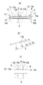
- (A) is side sectional drawing explaining the attachment state of the curvature prevention member same as the above
- (b) is an exploded perspective view of a curvature prevention member.
- (a) is a side view of the state which attached the television same as the above to the partition wall via the television attachment panel
- (b) is seen from the arrow F direction of (a).
- It is a front view explaining the arrangement
- (c) is a side view which shows the state which attached the active noise control speaker to the partition of the front side frame.
- FIG. 1 is a usage example of the television mounting panel 3 of the present embodiment
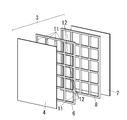
- FIG. 2 is an exploded perspective view of the television mounting panel 3.
- the TV mounting panel 3 includes both a front frame 6 to which the TV fixing plate 4 is mounted, a rear frame 8 to be mounted on the wall fixing plate 7, and a gap 9 formed between both the frames 6 and 8. It is comprised with the connection member 5 for mutually connecting a part of site
- the front frame 6 is configured by assembling a plurality of vertical frames 11 and a plurality of horizontal frames 12 in a lattice shape, as shown in FIG.
- the rear frame body 8 is a separate body from the front frame body 6 and is configured in a lattice shape having the same structure and the same size as the front frame body 6.
- a flat TV fixing plate 4 whose front surface is the TV installation surface is attached to the front surface of the front frame 6 by fixing means (not shown).
- a flat plate-like wall fixing plate 7 whose rear surface is a wall mounting surface is attached to the rear surface of the rear frame 8 by an adhering means (not shown).
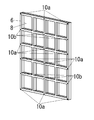
- the connecting member 5 a part of the portion where the vertical frame 11 and the horizontal frame 12 of the front frame 6 intersect with each other, and the vertical frame 11 and the horizontal frame 12 of the rear frame 8 facing this part of the connecting member 5 intersect. Some parts are connected to each other.
- the part of both frame bodies 6, 8 connected by the connecting member 5 is referred to as a first intersecting portion 10a, and the other part of both frame bodies 6, 8 not connected by the connecting member 5 is the second intersection. This is referred to as part 10b.
- intersection part 10b is joined using the curvature prevention member 20 (FIG. 5) mentioned later.
- the connecting member 5 that connects the first intersecting portion 10a will be described.
- the connecting member 5 of this example has a joining spacer 14 sandwiched between a pair of joining sleeves 13, 13 and fastens both joining sleeves 13, 13 with bolts 15 and nuts 16. It is.
- Through holes 17 are formed in the first intersecting portions 10a of both frame bodies 6 and 8 so as to penetrate in the front-rear direction.
- a recess 18 a that is open forward to accommodate the head of the bolt 15 is formed, and at the rear end of the through hole 17 of the rear frame body 8 is a nut.
- a recess 18b that is open to the rear where 16 can be stored is formed.
- a tubular portion 13 a of one joining sleeve 13 is embedded in the through hole 17 of the front frame 6, and a flange portion 13 b provided at the rear end of the tubular portion 13 a is in close contact with the back surface of the front frame 6. It is exposed in the state.
- a tubular portion 13 a of the other joining sleeve 13 is embedded in the through hole 17 of the rear frame 8, and a flange portion 13 b provided at the front end of the tubular portion 13 a is formed on the front surface of the rear frame 8. Exposed in close contact.
- a cylindrical joining spacer 14 is interposed between the flange portions 13b, 13b of the joining sleeves 13, 13.
- the joining spacer 14 is arranged coaxially with the joining sleeves 13 and 13, and both ends in the axial direction of the joining spacer 14 are flange portions of both joining sleeves 13 as shown in FIG.
- the contact surfaces 14a are in contact with the outer surfaces of 13b. Further, in order to make it difficult for vibration to propagate, each contact surface 14 a is formed in a tapered shape with a sharp tip, and the contact surface 14 a is a point (or a circle) with respect to the flange portion 13 b of the joining sleeve 13. ) To come into contact.
- the vibration propagation from the front frame 6 to the rear frame 8 is limited to the elongated bolt 15.
- vibration propagation from the TV fixing plate 4 (TV installation surface side) to the wall fixing plate 7 (wall surface side) through the connecting member 5 is sufficiently suppressed, and the sound insulation performance on the TV rear side is greatly improved. There is.
- the warpage preventing member 20 of the present example includes a front connection tool 21 having a flange portion 21 b on the front end side and a convex connection surface 21 a protruding further toward the front end than the flange portion 21 b,
- the rear connection tool 22 has a flange portion 22b on the side and a concave connection surface 22a that protrudes further toward the tip than the flange portion 22b.
- the base portions are embedded in the frame bodies 6 and 8 rather than the flange portions 21b and 22b of the connection tools 21 and 22, respectively, and the connection surfaces 21a and 22a at the tips are butted together.
- connection surface 21a of the front connection tool 21 has a sharp convex shape
- connection surface 22a of the rear connection tool 22 has a round concave shape.
- both the connection surfaces 21a and the flange 22a are in point contact with each other, vibration propagation is suppressed and at the same time point contact is made with a certain degree of freedom.
- the connection surfaces 21a and 22a of both the connectors 21 and 22 are not deformed by the tightening load.
- the convex connection surface 21a of the front connection tool 21 is reliably received, and the contact position does not shift.
- both the frame bodies 6 and 8 is abutted in contact with the warpage preventing member 20 (FIG. 5), so that the number of the connecting members 5 is not increased.
- the joining strength of the frames 6 and 8 can be secured.
- the vibration propagation of the warp preventing member 20 itself is extremely small. Therefore, since both the frame bodies 6 and 8 can be fastened more reliably and strongly using the connecting member 5 and the warp preventing member 20, the television mounting panel 3 can sufficiently withstand the load of the television 1 and at the same time. It is also possible to demonstrate an excellent effect in sound insulation on the back of the TV.
- the TV mounting panel shown in FIG. 1 is interposed between the partition wall of the building and the TV.
- the television mounting panel is used for placing a television on the partition wall.
- the television mounting panel includes a television fixing plate 4, a front side frame body 6, a wall fixing plate 7, and a rear side frame body 8.
- the TV fixing plate 4 is configured to fix the TV.
- the television fixing plate 4 is configured to hold the television.
- the front frame 6 is attached to the television fixing plate 4.
- the wall fixing plate 7 is fixed to the partition wall. In other words, the wall fixing plate 7 is attached to the partition wall.
- the television mounting panel further includes a connecting member 5.
- the connecting member 5 connects a part of the opposed portions of the front frame body 6 and the rear frame body 8 to each other. Thereby, the front side frame body 6 is arrange
- the front frame body 6 has a portion facing the rear frame body 8.
- the rear frame 8 has a portion facing the front frame 6.
- the front side frame body 6 has a front side connecting portion at a portion facing the rear side frame body 8.
- the rear side frame body 8 has a rear side connection portion at a portion facing the front side frame body 6.
- the front side connecting portion is located at a position facing the rear side connecting portion.
- the connecting member 5 connects the front connecting part to the rear connecting part in a state where a gap is formed between the front frame 6 and the rear frame 8 with a predetermined interval.
- the front frame 6 has a plurality of vertical frames and a plurality of horizontal frames.
- the plurality of vertical frames and the plurality of horizontal frames are assembled in a lattice shape.
- the connecting member 5 includes a part of a portion where the vertical frame and the horizontal frame intersect in the front frame 6 and a portion of the portion where the vertical frame and the horizontal frame intersect in the rear frame 8 facing this part.
- the front frame 6 has a plurality of vertical frames and a plurality of horizontal frames.
- the plurality of vertical frames of the front frame 6 and the plurality of horizontal frames of the front frame 6 are assembled in a lattice shape. Therefore, the vertical frame of the front frame 6 intersects with the horizontal frame of the front frame 6, and a part of the portion where the vertical frame of the front frame 6 and the horizontal frame of the front frame 6 intersect is the second frame of the front frame 6. It is defined as one intersection 10a.
- the rear frame 8 has a plurality of vertical frames and a plurality of horizontal frames. The plurality of vertical frames of the rear frame 8 and the plurality of horizontal frames of the rear frame 8 are assembled in a lattice shape.
- the vertical frame of the rear frame 8 intersects with the horizontal frame of the rear frame 8, and a part of the portion where the vertical frame of the rear frame 8 and the horizontal frame of the rear frame 8 intersect is It is defined as the first intersection 10 a of the frame body 8.
- the connecting member 5 connects the first intersecting portion 10 a of the front frame 6 and the first intersecting portion 10 a of the rear frame 8.
- the portion where the strength of the front frame 6 is high can be attached to the portion where the strength of the rear frame 8 is high with the connecting member 5.
- the television mounting panel includes a warpage preventing member 20.
- the warp prevention member 20 is configured to join the front side frame body 6 and the rear side frame body 8 to each other at a predetermined interval.
- the warpage preventing member 20 joins parts of the front frame body 6 and the rear frame body 8 that are not connected by the connecting member 5 to each other with a predetermined interval therebetween.
- the warpage preventing member 20 has a front connection tool 21 and a rear connection tool 22.
- the front connector 21 is attached to the front frame 6 so as to protrude in the direction opposite to the TV fixing plate 4.
- the front connection tool 21 has a connection surface 21a.
- the connection surface 21 a of the front connection tool 21 is located on the opposite side of the television fixing plate 4 when viewed from the front frame body 6.
- the rear connection tool 22 is attached to the rear frame 8 so as to protrude in the direction opposite to the wall fixing plate 7.
- the rear connection tool 22 has a connection surface 22a.
- the front frame 6 is connected to the rear frame 8 by the connecting member 5 so that the connection surface 21a of the front connection tool 21 and the connection surface 22a of the rear connection tool 22 are in contact with each other.
- the warp preventing member 20 can be used to prevent the front frame 6 and the rear frame 8 from warping, and the bonding strength can be improved.
- connection surface 21a of the front connection tool 21 is formed in a sharp convex shape.
- connection surface 22a of the rear connection tool 22 is formed in a rounded concave shape.
- connection surface 21a of the front connection tool 21 comes into contact with the connection surface 22a of the rear connection tool 22 in a small area. Therefore, it is possible to reduce the vibration received by the front connection tool 21 from being propagated to the rear connection tool 22.
- FIG. 6 shows still another embodiment, in which the back surface of the front frame 6 of the TV mounting panel 3 is closed with a back plate 25 serving as a partition wall.
- An active noise control speaker 30 (hereinafter referred to as a control speaker 30) that outputs a control sound for muting the sound coming out from the back of the television 1 is attached to the front side of the back plate 25.
- gap part 9 between both frame bodies 6 and 8 and connects with the connection member 5 is the same as that of the said embodiment.
- so-called active noise control is performed in which the control sound output from the control speaker 30 is phase-interfered with the sound of the television 1 to cancel the sound from the television 1.
- This active noise control technique is known, for example, in Japanese Patent Application Laid-Open No. 2008-32767, and detailed description thereof is omitted.
- the hatched portion R in FIG. 6B indicates an area where a plurality of control speakers 30 are arranged.
- the television mounting panel 3 of the present example has the control speaker 30 built in the front frame 6, and drives the control speaker 30 when viewing the television 1 to generate an audio output that cancels the audio of the television 1. By doing so, it is possible to obtain a sound muting effect of the sound leaking behind the television 1.
- the vibration of the control speaker 30 itself or the reverse phase sound generated by the acoustic vibration radiated from the back surface of the control speaker 30 stops solidly propagating from the back plate 25 to the front frame body 6, The vibration propagation to the rear frame 8 connected by the connecting member 5 is sufficiently suppressed.
- the sound insulation performance on the back of the television 1 can be further improved by outputting sound from the television 1 and driving (sound output) the control speaker 30 inside the television mounting panel 3.
- the television mounting panel further includes a back plate 25 defined as a partition wall.
- This partition is arranged so as to close the back side of the front frame 6.
- the partition wall is disposed on the opposite side of the television fixing plate 4 when viewed from the front frame body 6.
- the television mounting panel further includes an active noise control speaker 30.
- the active noise control speaker 30 is attached to the back plate 25 so as to be positioned between the television fixing plate 4 and the back plate 25.
- FIG. 7 shows still another embodiment, and shows an example in which a damping material 40 is interposed between both frame bodies 6 and 8 of the television mounting panel 3.
- gap part 9 between both frame bodies 6 and 8 and connects with the connection member 5 is the same as that of the said embodiment.
- the damping material 40 for example, a sheet-like material having a vibration absorbing function such as rubber, plastic, and asphalt is used. This sheet-like material is the same size as the two frames 6 and 8.
- the vibration-damping material 40 is sandwiched between the two frame bodies 6 and 8, and the both frame bodies 6 and 8 are connected to each other by the connecting member 5 shown in FIG.
Landscapes
- Engineering & Computer Science (AREA)
- General Engineering & Computer Science (AREA)
- Mechanical Engineering (AREA)
- Finishing Walls (AREA)
- Details Of Audible-Bandwidth Transducers (AREA)
- Devices For Indicating Variable Information By Combining Individual Elements (AREA)
Abstract
テレビを固定するテレビ固定板と、このテレビ固定板に取り付けられる前側枠体と、間仕切壁に固定される壁固定板と、この壁固定板に取り付けられる後側枠体と、前記前側枠体と前記後側枠体との間に所定間隔を隔てて空隙部を形成した状態で前記前側枠体と前記後側枠体との対向する部位の一部を互いに連結する連結部材とを備えたテレビ取付パネル。
Description
本発明は、テレビ取付パネルに関し、詳しくは例えば液晶テレビ、プラズマテレビ等の薄型テレビを壁に取付けるために用いるテレビ取付パネルの構造に関するものである。
従来、薄型テレビを壁掛けして視聴する際に、住宅の躯体(例えば、間仕切壁)にテレビを直接取り付けるのではなく、専用のテレビ取付パネルに掛けるようにし、またテレビ視聴時にテレビの音声が間仕切壁背後の隣室へ漏れないようにする様々な工夫が試みられている。
また、テレビ取付パネルの背面への固体振動の伝播を抑える方法として、テレビ取付パネル自体の重量を増大させたり、或いは、テレビ取付パネルの奥行き寸法を増加させることが考えられる。しかしテレビ取付パネル自体の重量を増大させると、実際に住宅に設置する場合に搬入や設置が困難になる。また、テレビ取付パネルの奥行き寸法を増加させると、薄型テレビを掛けて設置しようとしているにもかかわらず、壁の前方への突出寸法が大きくなってしまうため、薄型テレビを掛けて視聴する意味がなくなる。
そこで、従来より、図8に示すように、床51から天井52までの高さを有する枠体53の前面に取付けた前板54の前面の一部を薄型テレビ1を取付けるテレビ取付け部55とすると共に、該前板54のテレビ取付け部55の背面側に補強板56を設けてテレビ固定用補助壁体57を構成する。該テレビ固定用補助壁体57を床51と天井52とにわたるように立設してテレビ固定用補助壁体57を住宅に対して床51と天井52とにのみ固定する。さらに枠体53の前板54の背面と壁58との間の上下複数箇所に中横枠60を架設することで、テレビ固定用補助壁体57と壁58との間に空間59を形成した構造が知られている(例えば特許文献1参照)。
他の従来例として、テレビやモニター等の画像表示装置を壁面に沿わせるように取り付けるに際して、内部が空洞となった扁平箱形のスペースユニットを壁に沿うようにして組み付ける。このスペースユニットの前面板に対して画像表示装置を取り付けるようにした構造が知られている(例えば、特許文献2参照)。
しかし、上記特許文献1に示される従来例にあっては、テレビ固定用補助壁体57の補強板56と壁58との間に振動伝播を抑えるための空間59を形成しているが、テレビ1を視聴する際にテレビ1を振動源とする固体振動が、空間59を確保するために設けた上下複数の中横枠60を介して、壁58に伝わるという問題がある。
また上記特許文献2の従来例では、テレビを視聴する際にテレビを振動源とする固体振動が内部が空洞となっているスペースユニットの外郭部分を伝って、壁面に伝わるという問題がある。このため、いずれの従来例においても、テレビ背面の遮音性能が十分ではなかった。
本発明は上記の事情に鑑みてなされたものであって、その目的とするところは、テレビを振動源とする固体振動がテレビ設置面側から壁面側へ伝播するのを抑制できるテレビ取付パネルを提供することにある。
前記の課題を解決するために、本発明のテレビ取付パネルは、建物の間仕切壁とテレビとの間に介在され、間仕切壁に対してテレビを掛けるためのテレビ取付パネルであって、前記テレビを固定するテレビ固定板と、このテレビ固定板に取り付けられる前側枠体と、前記間仕切壁に固定される壁固定板と、この壁固定板に取り付けられる後側枠体と、前記前側枠体と前記後側枠体との間に所定間隔を隔てて空隙部を形成した状態で前記前側枠体と前記後側枠体との対向する部位の一部を互いに連結する連結部材とを備えている。
前記前側枠体の背面側を隔壁で塞ぐと共に、この隔壁の前面側に前記テレビ背後から漏れる音声を消音するための制御音を出力する能動騒音制御用スピーカを取り付けることが好ましい。
前記前側枠体と前記後側枠体との間に制振材を配置することが好ましい。
前記前側枠体と前記後側枠体は、それぞれ、複数本の縦枠と複数本の横枠とを格子状に組み立てて構成されると共に、前記前側枠体における縦枠と横枠とが交わる部位の一部と、この一部の部位に対向する前記後側枠体における縦枠と横枠とが交わる一部の部位とを、前記連結部材で連結してなることが好ましい。
前記連結部材で連結されない前記前側枠体と前記後側枠体の部位の一部を、所定間隔を隔てて互いに接合するための反り防止部材を備えることが好ましい。
テレビを振動源とする固体振動がテレビ取付パネルのテレビ設置面側から壁面側へ伝播するのを抑制できる。
以下、本発明の実施の形態について、図面を参照しながら説明する。
図1は本実施形態のテレビ取付パネル3の使用例であり、図2はテレビ取付パネル3の分解斜視図である。
テレビ取付パネル3は、テレビ固定板4を取り付けた前側枠体6と、壁固定板7に取り付けられる後側枠体8と、両枠体6,8間に空隙部9を形成した状態で両枠体6,8の対向する部位の一部を互いに連結するための連結部材5とで構成される。
前側枠体6は、図2に示すように、複数の縦枠11と複数の横枠12とを格子状に組み立てて構成されている。後側枠体8は、前側枠体6とは別体であり、前側枠体6と同じ構造、同じ大きさの格子状に構成されている。
前側枠体6の前面には、前面がテレビ設置面となる平板状のテレビ固定板4が固着手段(図示せず)により取り付けられる。後側枠体8の背面には、背面が壁取り付け面となる平板状の壁固定板7が固着手段(図示せず)により取り付けられる。
連結部材5は、前側枠体6の縦枠11と横枠12とが交わる部位の一部と、この一部の部位に対向する後側枠体8の縦枠11と横枠12とが交わる一部の部位とを、互いに連結するものである。図3において、連結部材5で連結される両枠体6,8の部位を、第1交差部10aと称し、連結部材5で連結されない両枠体6,8の他の部位を、第2交差部10bと称する。尚、第2交差部10bは後述する反り防止部材20(図5)を用いて接合される。
上記第1交差部10aを連結する連結部材5について説明する。
本例の連結部材5は、図4に示すように、一対の接合用スリーブ13,13間に接合用スペーサ14を挟み、ボルト15とナット16で両接合用スリーブ13,13を互いに締結するものである。
両枠体6,8の第1交差部10aには、それぞれ、前後方向に貫通する貫通穴17が形成されている。前側枠体6の貫通穴17の前端にはボルト15の頭部が収納可能な前方に開放された凹所18aが形成されており、後側枠体8の貫通穴17の後端にはナット16が収納可能な後方に開放された凹所18bが形成されている。
前側枠体6の貫通穴17内には、一方の接合用スリーブ13の管状部13aが埋設されていると共にこの管状部13aの後端に設けたフランジ部13bが前側枠体6の背面に密着した状態で露出している。
後側枠体8の貫通穴17内には、他方の接合用スリーブ13の管状部13aが埋設されていると共にこの管状部13aの前端に設けたフランジ部13bが後側枠体8の前面に密着した状態で露出している。
上記両接合用スリーブ13,13のフランジ部13b,13b間には、筒状の接合用スペーサ14が介在される。接合用スペーサ14は、接合用スリーブ13,13と同軸方向に配置され、接合用スペーサ14の軸方向の両端は、それぞれ、図4(c)に示すように、両接合用スリーブ13のフランジ部13bの外面にそれぞれ当接する当接面14aとなっている。また振動が伝播しにくくするために、当接面14aはそれぞれ、先端が尖った断面先細状に形成されており、当接面14aが接合用スリーブ13のフランジ部13bに対して点(或いは円)で接触するようになっている。
両枠体6,8の第1交差部10aを連結するにあたっては、ボルト15を前側枠体6の凹所18a側から貫通穴17内の一方の接合用スリーブ13内に通し、さらに接合用スペーサ14内から他方の接合用スリーブ13内を貫通して後側枠体8の凹所18b内に突出させると共に、凹所18b内においてナット16がボルト15の先端に締結される。このボルト・ナット締結により、両枠体6,8が第1交差部10aで互いに連結されると同時に、接合用スペーサ14により両枠体6,8間には所定間隔を隔てて空隙部9が確保された状態となる。
しかして、テレビ1を視聴する際には、テレビ1を振動源とする固体振動や、テレビ1の音声が一旦室内側に放射されて、回折や反射によりテレビ取付パネル3の表面に到来した音波は、テレビ取付パネル3の空隙部9において吸収される。さらに、空隙部9を挟んで隣り合う両枠体6,8は、図1(a)(b)に示すように、互いに交差する一部の第1交差部10aのみで、空隙部9を確保した状態で連結部材5で連結されているので、両枠体6,8間の振動を伝播する部材は連結部材5のみとなる。
ここで、図4において、連結部材5のうち、一方の接合用スリーブ13から接合用スペーサ14を介して他方の接合用スリーブ13への振動伝播については、本例では、接合用スペーサ14の両端に設けた当接面14aは、それぞれ、先端が尖った断面先細状に形成されている。そして、この当接面14aが接合用スリーブ13のフランジ部13bに対して点(或いは円)で接触することで、接合用スペーサ14と接合用スリーブ13との接触面積が極力小さくなり、接合用スペーサ14による振動伝播が極力抑えられるものである。
従って、前側枠体6から後側枠体8への振動伝播は、細長いボルト15のみとなる。この結果、テレビ固定板4(テレビ設置面側)から連結部材5を介して壁固定板7(壁面側)への振動伝播が十分に抑制され、テレビ背面側の遮音性能が大幅に向上する利点がある。
ところで、前側枠体6と後側枠体8とをボルト15とナット16で締結する場合において、振動伝播をより減少させるためには、例えばボルト・ナット締結部の数を減らすことが考えられる。しかし、あまりに減らしすぎると、両枠体6,8の接合強度が低下してしまう不都合が生じる。また両枠体6,8のボルト15で締結されない部位では、両枠体6,8が互いに浮いた状態にあり、仮りに枠体6,8のいずれかに反りが発生すると、浮いた部分で枠体6,8同士が接触して振動を伝播させてしまう不都合もある。
そこで本例では、図3に示した連結部材5で連結されない両枠体6,8の第2交差部10bにおいて、反り防止部材20を用いて両枠体6,8の反り発生防止及び接合強度向上とを図っている。
本例の反り防止部材20は、図5に示すように、先端側にフランジ部21bとこのフランジ部21bよりも更に先端に突出する凸面状の接続面21aとを有する前側接続具21と、先端側にフランジ部22bとこのフランジ部22bよりも更に先端に突出する凹面状の接続面22aとを有する後側接続具22とからなる。各接続具21,22のフランジ部21b、22bよりも根元部分を枠体6,8内にそれぞれ埋め込み、先端の接続面21a,22a同士を突き合わせる。ここでは、前側接続具21の接続面21aは尖った凸面状になっており、一方、後側接続具22の接続面22aは丸みのある凹面状になっている。そして、両接続面21a, 22aが点接触することで振動伝播が抑えられると同時に、一定の自由度をもって点接触しているため、ボルト15とナット16とで強力に両枠体6,8を締結したときもその締め付け荷重によって両接続具21,22の接続面21a,22aが変形することがなくなる。また、後側接続具22の凹面状の接続面22aの面積が小さくても前側接続具21の凸面状の接続面21aを確実に受け止めるようになり、接触する位置がずれることもなくなる。
このように、両枠体6,8の第2交差部10b(図3)を反り防止部材20(図5)で接触状態で突き当てることで、連結部材5の数を増加させることなく、両枠体6,8の接合強度を確保できるようになる。これと同時に、反り防止部材20自体の振動伝播はきわめて小さいものである。従って、両枠体6,8を連結部材5と反り防止部材20とを用いてより確実に且つ強力に締結できるので、テレビ取付パネル3をテレビ1の荷重に十分に耐え得るものとしながら、同時にテレビ背面への遮音性にも優れた効果を発揮することができる。
以上述べたように、図1に示すテレビ取付パネルは、建物の間仕切壁とテレビとの間に介在されるものである。そして、テレビ取付パネルは、間仕切壁に対してテレビをかけるためのものである。テレビ取付パネルは、テレビ固定板4と、前側枠体6と、壁固定板7と、後側枠体8とを備える。テレビ固定板4は、テレビを固定するように構成されている。言い換えると、テレビ固定板4は、テレビを保持するように構成されている。前側枠体6は、テレビ固定板4に取り付けられる。壁固定板7は、間仕切壁に固定される。言い換えると、壁固定板7は、間仕切壁に取り付けられる。テレビ取付パネルは、さらに連結部材5を備える。
連結部材5は、前側枠体6と後側枠体8との対向する部位の一部を互いに連結する。これにより、前側枠体6は、後側枠体8から、所定間隔を隔てて空隙部を形成した状態で配置される。
言い換えると、前側枠体6は、後側枠体8と対向する部分を有する。同様に、後側枠体8は、前側枠体6と対向する部分を有する。前側枠体6は、後側枠体8と対向する部分に、前側連結部を有する。後側枠体8は、前側枠体6と対向する部分に、後側連結部を有する。前側連結部は、後側連結部と対向する位置に位置する。連結部材5は、前記前側枠体6と前記後側枠体8との間に所定間隔を隔てて空隙部を形成した状態で、前側連結部を後側連結部に連結する。
これにより、テレビを振動源とする固体振動がテレビ取付パネルのテレビ設置面側から壁面側へ伝播するのを抑制できる。
また、前側枠体6は、複数本の縦枠と、複数本の横枠とを有する。複数本の縦枠と複数本の横枠とは、格子状に組み立てられている。連結部材5は、前側枠体6における縦枠と横枠とが交わる部位の一部と、この一部の部位に対向する後側枠体8における縦枠と横枠とが交わる一部の部位とを連結する。
言い換えると、前側枠体6は、複数本の縦枠と、複数本の横枠とを有する。前側枠体6の複数本の縦枠と前側枠体6の複数本の横枠とは、格子状に組み立てられている。したがって、前側枠体6の縦枠は前側枠体6の横枠と交わり、前側枠体6の縦枠と前側枠体6の横枠とが交わる部位の一部は、前側枠体6の第1交差部10aとして定義される。後側枠体8は、複数本の縦枠と、複数本の横枠とを有する。後側枠体8の複数本の縦枠と後側枠体8の複数本の横枠とは、格子状に組み立てられている。したがって、後側枠体8の縦枠は後側枠体8の横枠と交わり、後側枠体8の縦枠と後側枠体8の横枠とが交わる部位の一部は、後側枠体8の第1交差部10aとして定義される。そして、連結部材5は、前側枠体6の第1交差部10aと後側枠体8の第1交差部10aとを連結する。
これにより、前側枠体6の強度が高い部分を、後側枠体8の強度が高い部分に対して、連結部材5で取り付けることができる。
また、図5に示すように、テレビ取付パネルは、反り防止部材20を備えている。
反り防止部材20は、前側枠体6と後側枠体8とを、所定間隔隔てて互いに接合するように構成されている。
より詳しくは、反り防止部材20は、連結部材5で連結されない前側枠体6と後側枠体8の部位の一部を、所定間隔を隔てて互いに接合する。
そして、反り防止部材20は、前側接続具21と後側接続具22とを有している。前側接続具21は、テレビ固定板4と反対側の方向に向かって突出するように前側枠体6に取り付けられている。前側接続具21は、接続面21aを有している。前側接続具21の接続面21aは、前側枠体6から見てテレビ固定板4と反対側に位置する。後側接続具22は、壁固定板7と反対側の方向に向かって突出するように、後側枠体8に取り付けられている。後側接続具22は、接続面22aを有している。前側接続具21の接続面21aと後側接続具22の接続面22aとが接触するように、前側枠体6は、後側枠体8に対して連結部材5で連結されている。
これにより、反り防止部材20を用いて前側枠体6及び後側枠体8の反りの発生を防止でき、また、接合強度を向上できる。
また、前側接続具21の接続面21aは、凸面状に形成されている。これに対して、後側接続具22の接続面22aは、凹面状に形成されている。
より詳しくは、前側接続具21の接続面21aは、尖った凸面状に形成されている。これに対して、後側接続具22の接続面22aは、丸みのある凹面状に形成されている。
これにより、前側接続具21の接続面21aは、後側接続具22の接続面22aと、小さい面積で接触する。よって、前側接続具21が受けた振動が、後側接続具22に伝播されることを低減することができる。
図6は更に他の実施形態であり、テレビ取付パネル3の前側枠体6の背面を隔壁となる背面板25で塞いでいる。この背面板25の前面側に、テレビ1背後から出る音声を消音するための制御音を出力する能動騒音制御用スピーカ30(以下、制御スピーカ30と称する)を取着したものである。なお、両枠体6,8間に空隙部9を確保して連結部材5で連結する構成は前記実施形態と同様である。本例では制御スピーカ30から出力する制御音をテレビ1の音声に位相干渉させることでテレビ1からの音声を打ち消す、いわゆる能動騒音制御(アクティブ・ノイズ・コントロール)を行うものである。この能動騒音制御の技術は例えば、特開2008-32767号公報において公知であり、詳細な説明は省略する。なお図6(b)の斜線部分Rは複数個の制御スピーカ30が配置される領域を示している。
しかして、本例のテレビ取付パネル3は、前側枠体6内部に制御スピーカ30を内蔵しており、テレビ1の視聴時に制御スピーカ30を駆動して、テレビ1の音声を打ち消す音声出力を発生させることで、テレビ1背後に漏れる音声の消音効果が得られる。そのうえ、制御スピーカ30自身の振動や、制御スピーカ30の背面から放射される音響振動により発生する逆相音などは、背面板25から前側枠体6に固体伝播するのに止まり、空隙部9を隔てて連結部材5で連結された後側枠体8への振動伝播は十分に抑えられる。この結果、テレビ1から音声を出力し且つテレビ取付パネル3内部で制御スピーカ30を駆動(音声出力)することで、テレビ1背面への遮音性能を一層向上させることができる。
以上説明したように、テレビ取付パネルは、さらに、隔壁として定義される背面板25を備えている。この隔壁は、前側枠体6の背面側を塞ぐように配置されている。すなわち、隔壁は、前側枠体6から見て、テレビ固定板4と反対側に配置されている。そして、テレビ取付パネルは、能動騒音制御用スピーカ30をさらに有している。
能動騒音制御用スピーカ30は、隔壁の前面側に取り付けられている。
より詳しくは、能動騒音制御用スピーカ30は、テレビ固定板4と背面板25との間に位置するように、背面板25に取り付けられている。
そして、テレビの背後から漏れる音声を消去するための制御音を出力するように構成されている。
これにより、テレビ1背面への遮音性能を一層向上させることができる。
図7は、更に他の実施形態であり、テレビ取付パネル3の両枠体6,8間に制振材40を介在させた場合の一例を示している。なお、両枠体6,8間に空隙部9を確保して連結部材5で連結する構成は前記実施形態と同様である。本例では制振材40として、例えばゴム系、プラスチック系、アスファルト系等の振動吸収機能を有するシート状素材が用いられる。このシート状素材は両枠体6,8と同じ大きさとされる。両枠体6,8間に制振材40を挟み、図4に示した連結部材5で両枠体6,8を互いに連結することで、テレビ固定板4(テレビ設置面側)で発生した不要な振動を制振材40で吸収できるので、壁固定板7(壁面側)への振動伝播をより一層抑制できる。また制振材40を両枠体6,8間に挟み込むことで、空隙部9(図1)にゴミ、埃等の侵入を防ぐことができる利点もある。
1 テレビ
2 間仕切壁
3 テレビ取付パネル
4 テレビ固定板
5 連結部材
6 前側枠体
7 壁固定板
8 後側枠体
9 空隙部
11 縦枠
12 横枠
13 接合用スリーブ
14 接合用スペーサ
15 ボルト
20 反り防止部材
25 背面板(隔壁)
30 能動騒音制御用スピーカ
40 制振材
2 間仕切壁
3 テレビ取付パネル
4 テレビ固定板
5 連結部材
6 前側枠体
7 壁固定板
8 後側枠体
9 空隙部
11 縦枠
12 横枠
13 接合用スリーブ
14 接合用スペーサ
15 ボルト
20 反り防止部材
25 背面板(隔壁)
30 能動騒音制御用スピーカ
40 制振材
Claims (5)
- 建物の間仕切壁とテレビとの間に介在され、間仕切壁に対してテレビを掛けるためのテレビ取付パネルであって、前記テレビを固定するテレビ固定板と、このテレビ固定板に取り付けられる前側枠体と、前記間仕切壁に固定される壁固定板と、この壁固定板に取り付けられる後側枠体と、前記前側枠体と前記後側枠体との間に所定間隔を隔てて空隙部を形成した状態で前記前側枠体と前記後側枠体との対向する部位の一部を互いに連結する連結部材とを備えていることを特徴とするテレビ取付パネル。
- 前記前側枠体の背面側を隔壁で塞ぐと共に、この隔壁の前面側に前記テレビ背後から漏れる音声を消音するための制御音を出力する能動騒音制御用スピーカを取り付けたことを特徴とする請求項1記載のテレビ取付パネル。
- 前記前側枠体と前記後側枠体との間に制振材を配置したことを特徴とする請求項1又は2記載のテレビ取付パネル。
- 前記前側枠体と前記後側枠体は、それぞれ、複数本の縦枠と複数本の横枠とを格子状に組み立てて構成されると共に、前記前側枠体における縦枠と横枠とが交わる部位の一部と、この一部の部位に対向する前記後側枠体における縦枠と横枠とが交わる一部の部位とを、前記連結部材で連結してなることを特徴とする請求項1乃至3のいずれか一項に記載のテレビ取付パネル。
- 前記連結部材で連結されない前記前側枠体と前記後側枠体の部位の一部を、所定間隔を隔てて互いに接合するための反り防止部材を備えることを特徴とする請求項4記載のテレビ取付パネル。
Priority Applications (1)
| Application Number | Priority Date | Filing Date | Title |
|---|---|---|---|
| CN201180030741.9A CN103004183B (zh) | 2010-06-25 | 2011-03-31 | 电视机安装面板 |
Applications Claiming Priority (2)
| Application Number | Priority Date | Filing Date | Title |
|---|---|---|---|
| JP2010145397A JP5469547B2 (ja) | 2010-06-25 | 2010-06-25 | テレビ取付パネル |
| JP2010-145397 | 2010-06-25 |
Publications (1)
| Publication Number | Publication Date |
|---|---|
| WO2011162003A1 true WO2011162003A1 (ja) | 2011-12-29 |
Family
ID=45371207
Family Applications (1)
| Application Number | Title | Priority Date | Filing Date |
|---|---|---|---|
| PCT/JP2011/058227 Ceased WO2011162003A1 (ja) | 2010-06-25 | 2011-03-31 | テレビ取付パネル |
Country Status (3)
| Country | Link |
|---|---|
| JP (1) | JP5469547B2 (ja) |
| CN (1) | CN103004183B (ja) |
| WO (1) | WO2011162003A1 (ja) |
Cited By (1)
| Publication number | Priority date | Publication date | Assignee | Title |
|---|---|---|---|---|
| CN107012999A (zh) * | 2017-04-27 | 2017-08-04 | 长兴同创新材料科技有限公司 | 一种蜂窝式电视墙板建材结构 |
Families Citing this family (2)
| Publication number | Priority date | Publication date | Assignee | Title |
|---|---|---|---|---|
| JP2020148085A (ja) * | 2019-03-06 | 2020-09-17 | 株式会社Lixil | 骨組構造体 |
| TWI753635B (zh) * | 2020-11-03 | 2022-01-21 | 香港商冠捷投資有限公司 | 連接裝置 |
Citations (4)
| Publication number | Priority date | Publication date | Assignee | Title |
|---|---|---|---|---|
| JP2007224619A (ja) * | 2006-02-23 | 2007-09-06 | Matsushita Electric Works Ltd | テレビ固定用補助壁体の取付け構造 |
| JP2008019702A (ja) * | 2006-06-16 | 2008-01-31 | Matsushita Electric Works Ltd | テレビ固定用補助壁体とその施工方法 |
| JP2009279328A (ja) * | 2008-05-26 | 2009-12-03 | Panasonic Electric Works Co Ltd | 取付パネルの取付構造 |
| JP2010062796A (ja) * | 2008-09-03 | 2010-03-18 | 3Q:Kk | 画像表示装置用スペースユニットの取り付け方法及び取り付け構造 |
Family Cites Families (6)
| Publication number | Priority date | Publication date | Assignee | Title |
|---|---|---|---|---|
| US6554262B2 (en) * | 2001-08-23 | 2003-04-29 | Lockheed Martin Corporation | Wall mounted display |
| EP1471766B1 (en) * | 2003-04-22 | 2010-11-24 | Thomson Licensing | Electronic device with loudspeaker |
| KR200374579Y1 (ko) * | 2004-11-19 | 2005-02-02 | 툴디자인 (주) | 영상-음향 기기의 회전식 벽체 내장 시스템 |
| CN2896740Y (zh) * | 2006-04-21 | 2007-05-02 | 四川长虹电器股份有限公司 | 平板电视机壁挂装置 |
| CN201156791Y (zh) * | 2007-12-26 | 2008-11-26 | 康佳集团股份有限公司 | 平板电视壁挂架结构 |
| US20090278007A1 (en) * | 2008-05-08 | 2009-11-12 | Taylor Ronald W | System and method for mounting a flat panel device |
-
2010
- 2010-06-25 JP JP2010145397A patent/JP5469547B2/ja not_active Expired - Fee Related
-
2011
- 2011-03-31 WO PCT/JP2011/058227 patent/WO2011162003A1/ja not_active Ceased
- 2011-03-31 CN CN201180030741.9A patent/CN103004183B/zh not_active Expired - Fee Related
Patent Citations (4)
| Publication number | Priority date | Publication date | Assignee | Title |
|---|---|---|---|---|
| JP2007224619A (ja) * | 2006-02-23 | 2007-09-06 | Matsushita Electric Works Ltd | テレビ固定用補助壁体の取付け構造 |
| JP2008019702A (ja) * | 2006-06-16 | 2008-01-31 | Matsushita Electric Works Ltd | テレビ固定用補助壁体とその施工方法 |
| JP2009279328A (ja) * | 2008-05-26 | 2009-12-03 | Panasonic Electric Works Co Ltd | 取付パネルの取付構造 |
| JP2010062796A (ja) * | 2008-09-03 | 2010-03-18 | 3Q:Kk | 画像表示装置用スペースユニットの取り付け方法及び取り付け構造 |
Cited By (1)
| Publication number | Priority date | Publication date | Assignee | Title |
|---|---|---|---|---|
| CN107012999A (zh) * | 2017-04-27 | 2017-08-04 | 长兴同创新材料科技有限公司 | 一种蜂窝式电视墙板建材结构 |
Also Published As
| Publication number | Publication date |
|---|---|
| JP5469547B2 (ja) | 2014-04-16 |
| JP2012007417A (ja) | 2012-01-12 |
| CN103004183B (zh) | 2016-03-09 |
| CN103004183A (zh) | 2013-03-27 |
Similar Documents
| Publication | Publication Date | Title |
|---|---|---|
| JP5125427B2 (ja) | 表示装置 | |
| JP2012087549A (ja) | 建設機械の配管クランプ | |
| CN103975251B (zh) | 机动车的装配复合结构 | |
| JP5469547B2 (ja) | テレビ取付パネル | |
| CN114967313B (zh) | 显示装置、发声基板以及投影屏幕 | |
| JP2018123669A (ja) | 振動吸収部材、これを備えた建物の仕切構造および振動吸収部材の設置方法 | |
| JP5133117B2 (ja) | スピーカ取付構造、及び、スピーカ装置 | |
| JP6396224B2 (ja) | 防振耐震天井用接続金具 | |
| JP5022844B2 (ja) | 防音パネルおよび防音タンク | |
| JP5383598B2 (ja) | 建物 | |
| JP6744991B2 (ja) | ルーバー用パネルの取付構造 | |
| JP7224035B2 (ja) | 吸音ボードを支持するパネル支持構造 | |
| US20230092950A1 (en) | Display device | |
| KR100921307B1 (ko) | 차량의 엔진 마운트 | |
| JP4879568B2 (ja) | 建物 | |
| JP5858715B2 (ja) | 吸音パネルセット | |
| JPH1193292A (ja) | 防音室 | |
| JP3356622B2 (ja) | 床の防振構造 | |
| JP2011099301A (ja) | 床支持吸振具、及び、床構造 | |
| JP5363183B2 (ja) | 木造建築物用制震装置 | |
| JP5775443B2 (ja) | 天井構造 | |
| JP5824445B2 (ja) | 床構造 | |
| JP3870710B2 (ja) | 防音パネルの取付構造 | |
| JP2008271435A (ja) | 内装板音出力システム | |
| KR20070040678A (ko) | 디스플레이장치의 스피커 커버 장착구조 |
Legal Events
| Date | Code | Title | Description |
|---|---|---|---|
| WWE | Wipo information: entry into national phase |
Ref document number: 201180030741.9 Country of ref document: CN |
|
| 121 | Ep: the epo has been informed by wipo that ep was designated in this application |
Ref document number: 11797891 Country of ref document: EP Kind code of ref document: A1 |
|
| NENP | Non-entry into the national phase |
Ref country code: DE |
|
| 122 | Ep: pct application non-entry in european phase |
Ref document number: 11797891 Country of ref document: EP Kind code of ref document: A1 |