WO2011152264A1 - 炊飯器 - Google Patents
炊飯器 Download PDFInfo
- Publication number
- WO2011152264A1 WO2011152264A1 PCT/JP2011/062004 JP2011062004W WO2011152264A1 WO 2011152264 A1 WO2011152264 A1 WO 2011152264A1 JP 2011062004 W JP2011062004 W JP 2011062004W WO 2011152264 A1 WO2011152264 A1 WO 2011152264A1
- Authority
- WO
- WIPO (PCT)
- Prior art keywords
- inner pot
- stirring blade
- rice
- rice cooker
- convex portion
- Prior art date
- Legal status (The legal status is an assumption and is not a legal conclusion. Google has not performed a legal analysis and makes no representation as to the accuracy of the status listed.)
- Ceased
Links
Images














Classifications
-
- A—HUMAN NECESSITIES
- A47—FURNITURE; DOMESTIC ARTICLES OR APPLIANCES; COFFEE MILLS; SPICE MILLS; SUCTION CLEANERS IN GENERAL
- A47J—KITCHEN EQUIPMENT; COFFEE MILLS; SPICE MILLS; APPARATUS FOR MAKING BEVERAGES
- A47J27/00—Cooking-vessels
- A47J27/004—Cooking-vessels with integral electrical heating means
-
- A—HUMAN NECESSITIES
- A47—FURNITURE; DOMESTIC ARTICLES OR APPLIANCES; COFFEE MILLS; SPICE MILLS; SUCTION CLEANERS IN GENERAL
- A47J—KITCHEN EQUIPMENT; COFFEE MILLS; SPICE MILLS; APPARATUS FOR MAKING BEVERAGES
- A47J36/00—Parts, details or accessories of cooking-vessels
- A47J36/16—Inserts
- A47J36/165—Stirring devices operatively connected to cooking vessels when being removably inserted inside
-
- A—HUMAN NECESSITIES
- A47—FURNITURE; DOMESTIC ARTICLES OR APPLIANCES; COFFEE MILLS; SPICE MILLS; SUCTION CLEANERS IN GENERAL
- A47J—KITCHEN EQUIPMENT; COFFEE MILLS; SPICE MILLS; APPARATUS FOR MAKING BEVERAGES
- A47J43/00—Implements for preparing or holding food, not provided for in other groups of this subclass
- A47J43/04—Machines for domestic use not covered elsewhere, e.g. for grinding, mixing, stirring, kneading, emulsifying, whipping or beating foodstuffs, e.g. power-driven
- A47J43/046—Machines for domestic use not covered elsewhere, e.g. for grinding, mixing, stirring, kneading, emulsifying, whipping or beating foodstuffs, e.g. power-driven with tools driven from the bottom side
- A47J43/0465—Machines for domestic use not covered elsewhere, e.g. for grinding, mixing, stirring, kneading, emulsifying, whipping or beating foodstuffs, e.g. power-driven with tools driven from the bottom side with magnetic drive
Definitions
- the present invention relates to a rice cooker, and more particularly, to a water-stirring type household and commercial rice cooker using a stirring blade.
- Patent Document 1 does not have a detailed description of the means for generating water flow, but if there are square blades that stand up all over the inner pot when rice is loosened with rice scoop after cooking, There is a concern that the wings will always get in the way of the meal.
- the outer lid, the rotating shaft, and the blade are integrated, the outer lid cannot be opened and closed because the blade interferes with the inner pan when the outer lid is opened and closed.
- a conventional rice cooker having a second rice washing function it is provided with water flow generating means for allowing rice to flow in the inner pot in a reversal cycle in which a rotatable inner pot is rotated 180 degrees and reversely rotated.
- a method of washing rice without rubbing blades by rubbing see JP-A-1-212517 (Patent Document 2)).
- Patent Document 2 Japanese Patent Document 2
- the rice washing operation is performed two to three times. Therefore, the water replacement operation is the same as that of the rice washing by hand, and it is not possible to save much time and labor.
- a rice cooker provided with a water flow generating means for causing the stored water to flow has been proposed (see Japanese Patent Application Laid-Open No. 2000-308572 (Patent Document 3)).
- Patent Document 3 Japanese Patent Application Laid-Open No. 2000-308572
- the water in the inner pot is made to flow by the water flow generating means, heat transfer to the rice is improved, and heat control is performed to less than the boiling point, thereby suppressing the generation of water vapor and the good taste of fire. You can cook rice.
- the water flow generating means of the conventional first to third rice cookers have the following problems (1) to (5).
- the water stirring effect can be obtained when the amount of water is large and the rice cooking capacity is large, but at low rice cooking capacity (less than 2 go), the water amount is small and it can be rotated. As the rice is repelled by the blades and the rice is collected on the side wall in the inner pot, the water flow necessary for stirring cannot be obtained sufficiently with a low rice cooking capacity.
- an object of the present invention is to provide a water stirring type rice cooker that can stably rotate a stirring blade and can easily attach and detach the stirring blade after cooking.
- the rice cooker of this invention is A cylindrical convex portion protruding upward is provided at the bottom, and an inner pot for storing rice and water, A main body for housing the inner pot; A concave portion that is rotatably fitted to the convex portion of the inner pot is formed on the lower side, a stirring blade for stirring rice and water contained in the inner pot, A drive unit disposed below the inner pot and in the main body, and rotating the stirring blade in the inner pot through a radial magnetic coupling; A plurality of protrusions having a curved surface at the tip are provided at a position that is rotationally symmetric with respect to the rotation axis of the stirring blade on either the upper surface of the stirring blade on the concave portion or the upper end of the convex portion of the inner pot. With One of the upper surface of the concave portion of the stirring blade and the upper end of the convex portion of the inner pot is provided with a flat portion where the tips of the plurality of protrusions contact or approach each other
- the driving blade rotates the stirring blade through the radial type magnetic coupling, thereby generating a water flow in the inner pot and stirring the rice and water in the inner pot.
- the upper surface in the concave portion of the stirring blade and the upper end of the convex portion of the inner pot are a plurality of protrusions having a curved surface at the tip provided on the upper surface in the concave portion of the stirring blade (or the upper end of the convex portion of the inner pot) Point contact.
- the stirring blade can be rotated in a slightly lifted form. Therefore, the load is reduced even if contact is made due to the influence of water flow or the weight of rice.
- the stirring blade is supported at a rotationally symmetric position about the rotation axis, so that it changes according to the rice capacity. Stable rotation is possible regardless of the number of rotations during stirring, and a stable water flow can be generated. Therefore, a stable stirring blade with a small load can be rotated by point contact and magnetic coupling, and the stirring blade after rice cooking can be easily attached and detached.
- the drive unit includes a plurality of drive magnets arranged in an annular shape and a motor that rotates the drive magnets
- the stirring blade has a plurality of driven magnets arranged in an annular shape, While the inner pot is housed in the main body, the plurality of driving magnets of the driving unit are arranged in the convex portion of the inner pot, while the plurality of driven magnets of the stirring blade are It arrange
- the plurality of driving magnets of the driving unit are arranged in the convex portion of the inner pot, while the plurality of driven magnets of the stirring blade are disposed in the inner pot.
- the magnetic force balance point of the radial type magnetic coupling is set in the recess of the stirring blade.
- the rice cooker of one embodiment It is provided in the main body so as to surround at least the plurality of driving magnets of the driving unit, and when the inner pot is stored in the main body, the inner pot is fitted into the convex portion of the inner pot. A cylindrical cover for positioning was provided.
- the cylindrical cover provided on the main body surrounds at least the plurality of driving magnets of the driving unit, and when the inner pot is stored in the main body, the cylindrical cover is in the convex portion of the inner pot.
- the plurality of protrusions provided on either the upper surface in the concave portion of the stirring blade or the upper end of the convex portion of the inner pot are more than half the outer diameter of the flat portion of the convex portion of the inner pot. It is arranged along a circle having a large diameter and centering on the rotation axis of the stirring blade.
- the stirring blade is rotated by arranging a plurality of protrusions along a circle having a diameter larger than half of the outer diameter of the convex portion of the inner pot and having the rotation axis of the stirring blade as a center. Is stable and the stirring blade can be tilted with the protrusion on the concave portion of the stirring blade (or the convex portion of the inner pan) as a fulcrum even when the temperature of the inner pan is lowered and negative pressure is applied to the stirring blade. In addition, it becomes possible to put a fingertip into the gap with the inner pot that has spread due to the inclination of the stirring blade, and the stirring blade can be easily removed.
- the plurality of protrusions are provided on the upper surface in the concave portion of the stirring blade, A mark was provided on the outer peripheral portion on the plane including the rotation axis of the stirring blade and passing through one of the plurality of protrusions and on the upper side of the stirring blade.
- the mark is attached to the upper side of the stirring blade by providing a mark on a plane including at least one of the plurality of protrusions including the rotating shaft of the stirring blade and on the upper outer peripheral portion of the stirring blade.
- the stirring blade is tilted with the protrusion passing through the plane as a fulcrum, and the stirring blade is lifted on the opposite side in the radial direction, so that the stirring blade can be easily removed. .
- the user can easily remove the stirring blade by tilting.
- the stirring blade has a disk-shaped base, and a plurality of bowl-shaped blades provided on the upper side of the base and extending radially outward from the center of the base, The mark is provided on at least one of the plurality of hook-shaped wings.
- the stirring wing can be easily tilted by pushing the marked part of the wing part with a finger.
- the wing can be removed more easily.
- the rice cooker by the optimum water flow stirring can be performed by the water stirring type rice cooker which can stably rotate the stirring blade and can be easily attached and detached after the rice cooking. Can be done.
- FIG. 1 is a schematic cross-sectional view showing the configuration of a rice cooker according to an embodiment of the present invention.
- FIG. 2A is a top view of the inner pot of the rice cooker.
- FIG. 2B is a longitudinal sectional view of the inner pot.
- FIG. 2C is a side view of the inner pot.
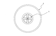
- FIG. 3A is a top view of the inner pot in which the stirring blades of the rice cooker are arranged.
- FIG. 3B is a plan view showing the structure of the magnetic coupling of the rice cooker.
- FIG. 3C is a longitudinal sectional view showing the structure of the magnetic coupling of the rice cooker.
- FIG. 3D is a vertical cross-sectional view of a main part on the lower side of the inner pot in which the stirring blade is arranged.
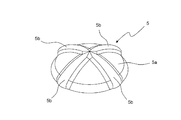
- FIG. 4A is a top view of the stirring blade.
- FIG. 4B is a side view of the stirring blade.
- FIG. 4C is a bottom view of the stirring blade.
- FIG. 4D is a perspective view of the agitating blade as viewed obliquely from above.
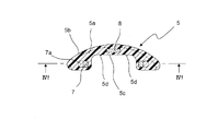
- FIG. 4E is a longitudinal sectional view of the stirring blade.
- FIG. 4F is a cross-sectional view of the stirring blade as seen from line IVf-IVf in FIG. 4E.
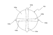
- FIG. 5A is a top view of a stirring blade according to another embodiment.
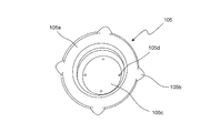
- FIG. 5B is a bottom view of the stirring blade.
- FIG. 5C is a perspective view of the stirring blade as viewed obliquely from below.
- FIG. 5D is a longitudinal sectional view of the stirring blade.
- FIG. 5A is a top view of a stirring blade according to another embodiment.
- FIG. 5B is a bottom view of the stirring blade.
- FIG. 5C is a perspective view
- FIG. 5E is a perspective view of the agitating blade as viewed obliquely from above.
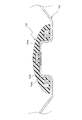
- FIG. 6A is a longitudinal sectional view showing a main part of the inner pot and a stirring blade.
- FIG. 6B is a longitudinal sectional view showing a main part of the inner pot and a tilted stirring blade.
- FIG. 6C is a longitudinal sectional view showing a main part of an inner pot and a stirring blade according to another embodiment.
- FIG. 6D is a longitudinal sectional view showing a main part of the inner pot and a tilted stirring blade.
- FIG. 7 is a longitudinal sectional view of a main part showing the stirring blade, the inner pot, the rice, and the gelatinized rice.
- FIG. 8A is a bottom view of a stirring blade according to another embodiment.
- FIG. 8B is a bottom view of a stirring blade according to another embodiment.
- FIG. 8C is a perspective view of a stirring blade according to another embodiment as viewed obliquely from above.
- FIG. 8D is a top view of a stirring blade according to another embodiment.
- FIG. 9 is a longitudinal sectional view of a main part showing another embodiment in which a protrusion is formed on the convex portion of the inner pot.
- An inner pot for storing rice and water a main body for storing the inner pot, a rotating blade that is rotatably mounted in the inner pot, and for stirring the rice and water stored in the inner pot,
- a rice cooker that is disposed in the lower side and in the main body and has a drive unit that rotates the stirring blade in the inner pot through a radial magnetic coupling, the stirring is rotatably fitted to the convex portion of the inner pot.
- stirring is performed during the rice washing process or during the rice cooking process until the start of gelatinization of the rice.
- the protrusion comes into contact with the upper end of the convex portion of the inner pot.
- the gap between the inner pot and the stirring blade is made smaller than the size of the rice grains so that the rice is difficult to enter during stirring.
- the air between the convex portion of the inner pan and the concave portion of the stirring blade is blocked with the gelatinized gap between the inner pan and the stirring blade, and It becomes difficult to remove the stirring blade due to the negative pressure due to the temperature drop.
- the stirring blade can be easily removed, but the possibility of the rice grains getting between the inner pot and the stirring blade during the stirring increases. If the rice grains are sandwiched between the convex part of the inner pot and the concave part of the stirring blade, the magnetic coupling may come off and stable rotation cannot be achieved. Increasing the gap between the side of the convex part of the inner pot and the concave part of the stirring blade increases the backlash of the stirring blade, making it easier to remove than the inner pot. In response, the central axis of the stirring blade rotates while shaking, so that it cannot rotate stably and the water flow is not stable.
- the stirring blade can be stably rotated, and the stirring blade after cooking can be easily attached and detached.
- FIG. 1 is a schematic cross-sectional view showing the configuration of a rice cooker A according to an embodiment of the present invention.
- the rice cooker A includes an outer case 21, a lid 22 attached to the upper side of the outer case 21 so as to be freely opened and closed, an outer pot 1 disposed in the outer case 21, and an outer pot. 1 has an inner pot 2 housed in 1, and a heater 3 disposed in the outer pot 1 and below the inner pot 2.
- the outer pot 1 is formed of a material having heat resistance and electrical insulation.
- the inner pot 2 is made of non-magnetic aluminum, and the inner surface thereof is coated with a fluororesin for preventing adhesion of an object to be heated.
- the outer case 21 and the outer pot 1 constitute a main body.
- an inner pot temperature sensor 10 having a tip penetrating the outer pot 1 is disposed below the outer pot 1.
- the inner pot temperature sensor 10 detects the temperature of the inner pot 2 by having the tip abutted near the bottom of the inner pot 2 housed in the outer pot 1.
- the output of the heater 3 is adjusted based on the temperature of the inner pot 2 detected by the inner pot temperature sensor 10.
- the cylindrical convex part 2a which protrudes upwards is provided in the bottom part of the said inner pot 2,
- the column-shaped recessed part which fits freely on the convex part 2a of the inner pot 2 below the stirring blade 5 is provided. 5c is formed.
- the mixture 11 of rice and water is stirred and flowed by the stirring blade 5 in which the concave portion 5c is rotatably fitted to the convex portion 2a of the inner pot 2.
- the convex part 2a of the inner pot 2 should just be not only cylindrical shape but a cylinder shape, it is desirable that it is cylindrical shape for smooth rotation of a stirring blade.
- the recess 5c of the stirring blade 5 is not limited to a columnar shape but may be a columnar shape, but it is desirable to have a columnar shape for smooth rotation of the stirring blade.
- the rice cooker A transmits a driving force by a magnetic coupling in a non-contact manner to the driven magnets 7 and the driven magnets 7 arranged in a ring shape in the stirring blade 5 accommodated in the inner pot 2.
- a plurality of driving magnets 6 arranged in an annular shape, a motor 4 for rotating the driving magnet 6, and provided in the outer case 21 so as to surround the driving magnet 6, are arranged in the convex portion 2 a of the inner pot 2.
- a cylindrical cover 9 that is fitted and positioned is provided.
- the motor 4 and the drive magnet 6 constitute a drive unit.
- the cover surrounding the driving magnet 6 is not limited to a cylindrical shape, but may be a cylindrical shape. However, it is desirable that the cover be a cylindrical shape for smooth rotation of the stirring blade.
- the rotational force of the motor 4 is transmitted to the stirring blade 5 through magnetic coupling by the driving magnet 6 and the driven magnet 7, and the stirring blade 5 rotates to generate a water flow.
- the water mixture 11 is stirred.
- FIG. 2A shows a top view of the inner pot 2 of the rice cooker
- FIG. 2B shows a longitudinal sectional view of the inner pot 2
- FIG. 2C shows a side view of the inner pot 2.
- the inner pot 2 is provided with a side wall 2c having a conical surface inclined toward the center in a lower half of the height direction. Moreover, the cylindrical convex part 2a which made the material of the inner pot 2 protrude toward the inner surface is formed in the center part of the bottom part of the inner pot 2. As shown in FIG. Moreover, the magnetic plate 2b is press-fitted into the outer surface side (lower side) of the flat portion at the upper end of the convex portion 2a of the inner pot 2.
- the inclination of the side wall 2c of the inner pot 2 is particularly effective when the rice cooking capacity is low.
- the water flow generated by the stirring blade 5 in the radial direction by the centrifugal force is naturally recirculated to the center by the inclination of the side wall, so that the water flow can be stirred without stagnation.
- This natural reflux is promoted as the angle of the side wall 2c of the inner pot 2 becomes steep, but the capacity decreases unless the diameter of the inner pot 2 is increased, so that the size and water flow of the inner pot 2 are balanced appropriately. What is necessary is just to set the angle to perform.
- the convex part 2a formed in the inner pot 2 is used as a shaft for rotatably supporting the stirring blade 5, and a cylindrical shape for positioning and preventing collision of the driving magnet 6 is provided inside the convex part 2a.
- the cover 9 is fitted to form a magnetic coupling by the driving magnet 6 and the driven magnet 7.
- the reason why the magnetic plate 2b is press-fitted on the outer surface side of the convex portion 2a is to exert an attractive action with the drop-preventing magnet 8 molded and enclosed in the stirring blade 5.
- a magnet attracting the magnet 8 may be provided, or a magnet may be provided on the convex portion 2a and the stirring blade 5 side may be a magnetic plate.
- FIG. 3A shows a top view of the inner pot 2 in which the stirring blade 5 of the rice cooker A is arranged
- FIG. 3B shows a plan view showing the structure of the magnetic coupling of the rice cooker A
- FIG. 3C shows the magnetism of the rice cooker A.
- the longitudinal cross-sectional view which shows the structure of a coupling is shown
- FIG. 3D has shown the longitudinal cross-sectional view of the principal part of the lower side of the inner pot 2 in which the stirring blade 5 is arrange
- six driving magnets 6 are mounted at equal intervals in the circumferential direction on the inner yoke 6a connected to the rotating shaft 4a of the motor 4 in the convex portion 2a of the inner pot 2, and the upper end is flat.
- the stirring blade 5 that is fitted to the convex portion 2a of the inner pot 2 through a cylindrical cover 9 that is closed by a portion and is integrally molded with fluororesin or the like, six outer magnets 7 are attached to the outer yoke 7a. Are mounted at equal intervals in the circumferential direction and positioned at a magnetic force balance point with the drive magnet 6.
- the six driving magnets 6 are alternately arranged with the driving magnets 6 having S poles on the outer side in the radial direction and the driving magnets 6 having N poles on the outer side in the radial direction.
- the six driven magnets 7 are alternately arranged such that the radially inner S-side driven magnet 7 and the radially inner N-pole driven magnet 7 are alternately arranged.
- the magnetic plate 2b press-fitted into the convex portion 2a of the inner pot 2 is attracted by the drop-off prevention magnet 8 at the center of the stirring blade 5, and the stirring blade 5 Prevents natural dropouts.
- FIG. 4A shows a top view of the stirring blade 5
- FIG. 4B shows a side view of the stirring blade 5
- FIG. 4C shows a bottom view of the stirring blade 5
- FIG. 4D is a perspective view seen from obliquely above the stirring blade 5.
- 4E is a longitudinal sectional view of the stirring blade 5
- FIG. 4F is a transverse sectional view of the stirring blade 5 as seen from the line IVf-IVf in FIG. 4E.
- the stirring blade 5 includes a disk-shaped base portion 5a, and four bowl-shaped blades for generating a water flow extending radially outward from the center above the base portion 5a.
- a portion 5b is provided.
- the stirring blade 5 is integrally formed of a driven magnet 7, an outer yoke 7 a and a drop-off prevention magnet 8 with a fluororesin or the like.
- the stirring blade 5 has a shape in which the scooping escapes along the curved surface, and the scrubbed slips in contact with the low friction of the fluororesin material, so that both water flow generation and good loosening properties are achieved.
- the shape and the blade portion of the stirring blade are not limited to this shape, and any shape can be used as long as the same effect can be exhibited.
- a water flow is generated in the inner pot 2 by rotating the stirring blade 5 via the radial magnetic coupling by the driving unit including the motor 4 and the driving magnet 6.
- the mixture 11 of rice and water in the inner pot 2 is stirred.
- the stirring blade 5 has a flat portion at the upper end of the convex portion 2 a of the inner pot 2 and a flat portion in the concave portion 5 c of the stirring blade 5 at the tip provided at the flat portion in the concave portion 5 c of the stirring blade 5.
- Point contact is achieved by a plurality of projections 5d having a curved surface.
- the magnetic force balance point of the radial type magnetic coupling connecting the stirring blade 5 and the drive unit is balanced to a position where the projection 5d and the flat portion at the upper end of the convex portion 2a of the inner pot 2 are not in contact with each other. 5 can be rotated in a slightly floating manner. Therefore, the load is reduced even if contact is made due to the influence of water flow or the weight of rice. Further, by providing the plurality of protrusions 5d at positions that are rotationally symmetric with respect to the rotation axis of the stirring blade 5, the stirring blade 5 is supported at a rotationally symmetric position about the rotation axis. Thus, stable rotation can be performed regardless of the number of rotations during stirring, and a stable water flow can be generated. Therefore, the stable stirring blade 5 with a small load can be rotated by point contact and magnetic coupling, and the stirring blade 5 after cooking can be easily attached and detached.
- a plurality of driving magnets 6 of the driving unit are disposed in the convex portion 2 a of the inner pot 2, while a plurality of driven magnets in the stirring blade 5 are disposed.
- 7 is arranged in the inner pot 2 and on the outer periphery of the convex portion 2a, and a radial type magnetic coupling is formed by a plurality of driven magnets 7 and a plurality of driving magnets 6; It is easy to rotate the stirring blade 5 in a slightly floating state by balancing the magnetic force balance point so that the projection 5d of the concave portion 5c of the stirring blade 5 does not contact the flat portion of the convex portion 2a of the inner pot 2. it can.
- the cylindrical cover 9 provided in the outer case 21 surrounds the plurality of driving magnets 6 of the driving unit, and when the inner pot 2 is stored in the outer pot 1, the cylindrical cover 9 is used as the inner pot 2.
- the inner pot 2 is positioned by fitting into the convex portion 2a of the inner pot 2 while preventing the plurality of driving magnets 6 and the like of the driving section from being soiled or damaged. It is possible to reliably perform positioning during storage.
- the stirring blade 5 rotates. Is stable and the stirring blade 5 can be tilted with the protrusion 5d on the concave portion 5c side of the stirring blade 5 as a fulcrum even in a state where the temperature of the inner pot 2 is lowered and a negative pressure is applied to the stirring blade 5. It becomes possible to put a fingertip into the gap with the inner pot 2 that is expanded by the inclination of the blade 5, and the stirring blade 5 can be easily removed. In addition, you may provide a protrusion in the upper end of the convex part 2a of the inner pot 2. As shown in FIG.
- the stirring blade is provided.
- the stirring blade 5 is inclined with the protrusion 5d passing through the plane as a fulcrum, and the stirring blade 5 is lifted on the opposite side to the mark 5e in the radial direction.
- the stirring blade 5 can be easily removed (see FIGS. 6A to 6D). Thereby, even if it is difficult for the user to remove the stirring blade 5 from before cooking rice due to the negative pressure, the user can easily remove the stirring blade 5 by inclining it.
- the stirring blade 5 can be easily tilted by pushing the mark 5e portion of the blade 5b with a finger. It can be easily removed.
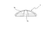
- FIG. 5A shows a top view of a stirring blade 105 of another embodiment
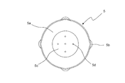
- FIG. 5B shows a bottom view of the stirring blade 105
- FIG. 5C shows a perspective view of the stirring blade 105 as viewed from obliquely below
- FIG. 5E is a perspective view of the stirring blade 105 as viewed from obliquely above.
- reference numeral 105a denotes a base
- 107 denotes a follower magnet
- 107a denotes an outer yoke
- 108 denotes a drop-off prevention magnet.
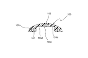
- a plurality of protrusions 105d are formed on the flat surface in the recessed portion 105c on the lower side of the stirring blade 105 fitted to the protruding portion 2a of the inner pot 2 shown in FIG.
- the plurality of protrusions 105 d come into contact with the flat portion of the convex portion 2 a of the inner pot 2, point contact occurs.
- the stirring blade 105 is slightly Rotating in a floating manner, the load is reduced even when touched by the influence of water flow and the weight of rice, and long-term reliability can be improved.
- the plurality of protrusions 105d are arranged at a rotationally symmetric position of 90 degrees with respect to the rotation axis on a flat surface in the concave portion 105c of the stirring blade 105, and are formed in a circular shape outside the concave portion 105c. Since the convex portion 2a is larger than half of the outer diameter, by pushing the mark 105e indicating the removal direction of the stirring blade 105 from above, the stirring blade 105 may be inclined with the lower protrusion 105d as a fulcrum. it can.
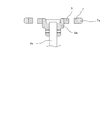
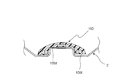
- FIG. 6A shows a longitudinal sectional view showing the main part of the inner pot 2 and the stirring blade 105
- FIG. 6B shows a longitudinal sectional view showing the main part of the inner pot 2 and the stirring blade 105 tilted.
- the protrusion 105d is arranged at a position that does not reach the radius R while being arranged along a circle having a diameter larger than half of the outer diameter of the convex portion 2a. If the diameter of the circle in which the protrusion 105d is arranged is smaller than half of the outer diameter of the convex portion 2a, the angle at which the stirring blade 105 is tilted becomes small. Removal is not easy.
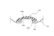
- protrusions are not limited to being formed on the stirring blade, and a plurality of protrusions 102d may be formed on the upper flat portion of the protrusion 102a of the inner pot 102 as shown in FIG.
- FIG. 6C shows the longitudinal cross-sectional view which shows the principal part of the inner pot 102 and stirring blade 105 of other embodiment
- FIG. 6D shows the longitudinal cross-sectional view which shows the main part of the inner pot 102 and the stirring blade 105 inclined. ing.
- the bottom of the inner pot 102 is provided with a cylindrical convex portion 102a protruding upward.
- An annular groove 102 b is provided on the outer periphery of the convex portion 102 a of the inner pot 102.
- the gap between the stirring blade 105 and the inner pot 102 shown in FIG. 6C is limited (a gap that does not contain rice grains is formed). Also in this case, as shown in FIG. 6D, by similarly inclining the stirring blade 105, a sufficient gap is opened to put a hand into the lower end 105f of the stirring blade 105, and can be easily removed.
- FIG. 7 is a configuration diagram of a cross section around the inner pot 2 and the stirring blade 105 after cooking, and the bottom of the inner pot 2 and the stirring blade 105 is covered with gelatinized rice 12a.
- the gap 13 between the convex portion 2a of the inner pot 2 and the concave portion 105c of the stirring blade 105 is in a negative pressure state due to the air in the gap 13 contracting due to a decrease in the temperature of the inner pot 2. Even in such a state, since the stirring blade 105 can be tilted with the protrusion 105d on the concave portion 105c side of the stirring blade 105 as a fulcrum, it is possible to put a fingertip into the gap with the inner pot 2 widened by the tilt of the stirring blade 105. This makes it possible to easily remove the stirring blade 105.
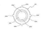
- FIG. 8A shows a bottom view of the stirring blade 205 of another embodiment.
- 205a is a base
- 205b is a bowl-shaped blade
- 205c is a recess.
- the protrusion 205d of the stirring blade 205 is provided along a circle having a rotational symmetry of 180 degrees and a diameter larger than half of the outer diameter of the convex portion of the inner pot, the number of protrusions 205d is 2. Even if it is individual, the same effect as the embodiment shown in FIGS. 1 to 4F can be obtained.
- FIG. 8B shows a bottom view of the stirring blade 305 of another embodiment.
- 305a is a base
- 305b is a bowl-shaped blade
- 305c is a recess.
- eight protrusions 305d of the stirring blade 305 are arranged in a rotational symmetry of 45 degrees. The number of protrusions may be four or more for more stable point contact.
- FIG. 8C shows a perspective view of an agitating blade 405 of another embodiment as viewed obliquely from above.
- the agitating blade 405 has a disc-shaped base portion 405a and a central portion on the upper side of the base portion 405a. 1 to FIG. 4F, a mark 405e indicating the removal direction of the stirring blade 405 is formed. The same effect as the embodiment can be obtained.
- the stirring blade 505 has a disk-shaped base portion 505a and a radial shape from the center above the base portion 505a. It has four bowl-shaped wings 505b for generating water flow extending outward in the radial direction, and marks 505e are respectively provided on the outer peripheral portions of the two wings 505b extending in the opposite directions in the radial direction from the center. ing.
- the mark 505e indicating the direction of removing the stirring blade 505 may have a different shape as long as it makes the user imagine pushing the stirring blade 505 from above.
- the rice cooker of the structure which heats the inner pot 2 with the heater 3 was demonstrated, the structure of the heating part which heats an inner pot is not restricted to this, For example, using an induction coil instead of a heater Also good.
Landscapes
- Engineering & Computer Science (AREA)
- Food Science & Technology (AREA)
- Mechanical Engineering (AREA)
- Cookers (AREA)
- Food-Manufacturing Devices (AREA)
Abstract
Description
また、内鍋内にご飯がなく、洗浄するような場合も羽根が落下して、損傷させ易い。
また、内鍋底面を平面として従動部(羽根)を内鍋内で回転させるため、水流や米の重みの影響を受けて羽根は中央からぶれるため、水流も安定しない。
上方に突出する筒形状の凸部が底部に設けられ、米と水を収容する内鍋と、
上記内鍋を収容する本体と、
上記内鍋の上記凸部に回転自在に嵌合する凹部が下側に形成され、上記内鍋内に収容された米と水を攪拌するための攪拌翼と、
上記内鍋の下側かつ上記本体内に配置され、上記内鍋内の上記攪拌翼をラジアル型の磁気カップリングを介して回転させる駆動部と
を備え、
上記攪拌翼の上記凹部内の上面または上記内鍋の上記凸部の上端のいずれか一方に、先端に曲面を有する複数の突起を上記攪拌翼の回転軸に対して回転対称となる位置に設けると共に、
上記攪拌翼の上記凹部内の上面または上記内鍋の上記凸部の上端のいずれか他方に、上記複数の突起の先端が接触または近接する平面部を設けたことを特徴とする。
上記駆動部は、環状に配列された複数の駆動用磁石と、上記駆動用磁石を回転させるモータとを有し、
上記攪拌翼は、環状に配列された複数の従動用磁石を有し、
上記内鍋が上記本体内に収納された状態で、上記駆動部の上記複数の駆動用磁石が上記内鍋の上記凸部内に配置される一方、上記攪拌翼の上記複数の従動用磁石が上記内鍋内かつ上記凸部の外周に配置されて、上記複数の従動用磁石と上記複数の駆動用磁石により上記ラジアル型の磁気カップリングを形成する。
上記駆動部の少なくとも上記複数の駆動用磁石を囲むように上記本体に設けられ、上記本体内に上記内鍋が収納されるときに上記内鍋の上記凸部内に嵌合して上記内鍋の位置決めを行う筒状のカバーを備えた。
上記攪拌翼の上記凹部内の上面または上記内鍋の上記凸部の上端のいずれか一方に設けられた上記複数の突起は、上記内鍋の上記凸部の平面部の外径の半分よりも直径が大きくかつ上記攪拌翼の回転軸を中心とする円に沿って配置されている。
上記複数の突起が上記攪拌翼の上記凹部内の上面に設けられており、
上記攪拌翼の回転軸を含み上記複数の突起のうちの1つを通る平面上、かつ、上記攪拌翼の上側の外周部分に印を設けた。
上記攪拌翼は、円盤状の基部と、上記基部の上側に設けられ、上記基部の中央から放射状に半径方向外側に向かって延びた畝状の複数の翼部とを有し、
上記印は、上記畝状の複数の翼部の少なくとも1つに設けられている。
1…外鍋
2,102…内鍋
2a,102a…凸部
2b…磁性板
2c…側壁
102b…溝部
102d…突起
3…ヒータ
4…モータ
4a…回転軸
5,105,205,305,405,505…攪拌翼
5a,105a,205a,305a,405a,505a…基部
5b,105b,205b,305b,405b,505b…翼部
5c,105c,205c,305c…凹部
5d,105d,205d,305d,405d…突起
5e,105e,405e,505e…印
6…駆動用磁石
6a…インナーヨーク
7…従動用磁石
7a…アウターヨーク
8,108…脱落防止用磁石
9…円筒形状のカバー
10…内鍋温度センサ
11…米と水の混合物
12…ご飯
12a…糊化した米
13…内鍋と攪拌翼の隙間(空気)
21…外ケース
22…蓋体
Claims (6)
- 上方に突出する筒形状の凸部が底部に設けられ、米と水を収容する内鍋(2,102)と、
上記内鍋(2,102)を収容する本体(1,21)と、
上記内鍋(2,102)の上記凸部に回転自在に嵌合する凹部が下側に形成され、上記内鍋(2,102)内に収容された米と水を攪拌するための攪拌翼(5,105,205,305,405,505)と、
上記内鍋(2,102)の下側かつ上記本体(1,21)内に配置され、上記内鍋(2,102)内の上記攪拌翼(5,105,205,305,405,505)をラジアル型の磁気カップリングを介して回転させる駆動部と
を備え、
上記攪拌翼(5,105,205,305,405,505)の上記凹部内の上面または上記内鍋(102)の上記凸部の上端のいずれか一方に、先端に曲面を有する複数の突起(5d,105d,205d,305d,405d)を上記攪拌翼(5,105,205,305,405,505)の回転軸に対して回転対称となる位置に設けると共に、
上記攪拌翼(5,105,205,305,405,505)の上記凹部内の上面または上記内鍋(102)の上記凸部の上端のいずれか他方に、上記複数の突起(5d,105d,205d,305d,405d)の先端が接触または近接する平面部を設けたことを特徴とする炊飯器。 - 請求項1に記載の炊飯器において、
上記駆動部は、環状に配列された複数の駆動用磁石(6)と、上記駆動用磁石(6)を回転させるモータ(4)とを有し、
上記攪拌翼(5,105,205,305,405,505)は、環状に配列された複数の従動用磁石(7)を有し、
上記内鍋(2,102)が上記本体(1,21)内に収納された状態で、上記駆動部の上記複数の駆動用磁石(6)が上記内鍋(2,102)の上記凸部内に配置される一方、上記攪拌翼(5,105,205,305,405,505)の上記複数の従動用磁石(7)が上記内鍋(2,102)内かつ上記凸部の外周に配置されて、上記複数の従動用磁石(7)と上記複数の駆動用磁石(6)により上記ラジアル型の磁気カップリングを形成することを特徴とする炊飯器。 - 請求項2に記載の炊飯器において、
上記駆動部の少なくとも上記複数の駆動用磁石(6)を囲むように上記本体(1,21)に設けられ、上記本体(1,21)内に上記内鍋(2,102)が収納されるときに上記内鍋(2,102)の上記凸部内に嵌合して上記内鍋(2,102)の位置決めを行う筒状のカバー(9)を備えたことを特徴とする炊飯器。 - 請求項1から3までのいずれか1つに記載の炊飯器において、
上記攪拌翼(5,105,205,305,405,505)の上記凹部内の上面または上記内鍋(2,102)の上記凸部の上端のいずれか一方に設けられた上記複数の突起(5d,105d,205d,305d,405d)は、上記内鍋(2,102)の上記凸部の平面部の外径の半分よりも直径が大きくかつ上記攪拌翼(5,105,205,305,405,505)の回転軸を中心とする円に沿って配置されていることを特徴とする炊飯器。 - 請求項1から4までのいずれか1つに記載の炊飯器において、
上記複数の突起(5d,105d,205d,305d,405d)が上記攪拌翼(5,105,205,305,405,505)の上記凹部内の上面に設けられており、
上記攪拌翼(5,105,205,305,405,505)の回転軸を含み上記複数の突起(5d,105d,205d,305d,405d)のうちの1つを通る平面上、かつ、上記攪拌翼(5,105,205,305,405,505)の上側の外周部分に印(5e,105e,405e,505e)を設けたことを特徴とする炊飯器。 - 請求項5に記載の炊飯器において、
上記攪拌翼(5,105,205,305,405,505)は、円盤状の基部(5a,105a,205a,305a,405a,505a)と、上記基部(5a,105a,205a,305a,405a,505a)の上側に設けられ、上記基部(5a,105a,205a,305a,405a,505a)の中央から放射状に半径方向外側に向かって延びた畝状の複数の翼部(5b,105b,205b,305b,405b,505b)とを有し、
上記印(5e,105e,405e,505e)は、上記畝状の複数の翼部(5b,105b,205b,305b,405b,505b)の少なくとも1つに設けられていることを特徴とする炊飯器。
Priority Applications (1)
| Application Number | Priority Date | Filing Date | Title |
|---|---|---|---|
| CN201180024748XA CN102892337A (zh) | 2010-06-01 | 2011-05-25 | 电饭锅 |
Applications Claiming Priority (2)
| Application Number | Priority Date | Filing Date | Title |
|---|---|---|---|
| JP2010-125513 | 2010-06-01 | ||
| JP2010125513A JP4792118B1 (ja) | 2010-06-01 | 2010-06-01 | 炊飯器 |
Publications (1)
| Publication Number | Publication Date |
|---|---|
| WO2011152264A1 true WO2011152264A1 (ja) | 2011-12-08 |
Family
ID=44881957
Family Applications (1)
| Application Number | Title | Priority Date | Filing Date |
|---|---|---|---|
| PCT/JP2011/062004 Ceased WO2011152264A1 (ja) | 2010-06-01 | 2011-05-25 | 炊飯器 |
Country Status (4)
| Country | Link |
|---|---|
| JP (1) | JP4792118B1 (ja) |
| CN (1) | CN102892337A (ja) |
| MY (1) | MY158185A (ja) |
| WO (1) | WO2011152264A1 (ja) |
Cited By (2)
| Publication number | Priority date | Publication date | Assignee | Title |
|---|---|---|---|---|
| WO2015019988A1 (ja) * | 2013-08-05 | 2015-02-12 | シャープ株式会社 | 撹拌羽根、撹拌装置、飲料製造装置および撹拌部 |
| CN114983221A (zh) * | 2021-03-02 | 2022-09-02 | (株)酷晨 | 烹饪机器 |
Families Citing this family (6)
| Publication number | Priority date | Publication date | Assignee | Title |
|---|---|---|---|---|
| CN105942831B (zh) * | 2016-07-14 | 2018-05-25 | 广东美的生活电器制造有限公司 | 榨汁机磁驱动结构和榨汁机 |
| JP6911036B2 (ja) * | 2016-09-02 | 2021-07-28 | シャープ株式会社 | 加熱調理器、制御プログラムおよび記録媒体 |
| CN108030357A (zh) * | 2018-01-24 | 2018-05-15 | 黄德懿 | 一种人体工程学的磁力搅拌杯具 |
| CN110575081A (zh) * | 2018-06-08 | 2019-12-17 | 佛山市顺德区美的电热电器制造有限公司 | 烹饪器具 |
| CN109349916B (zh) * | 2018-11-30 | 2022-11-18 | 湖南米米梦工场科技股份有限公司 | 一种蒸煮装置 |
| JP7586560B1 (ja) * | 2024-04-16 | 2024-11-19 | TechMagic株式会社 | 自動調理装置 |
Citations (4)
| Publication number | Priority date | Publication date | Assignee | Title |
|---|---|---|---|---|
| JPH0438918A (ja) * | 1990-06-01 | 1992-02-10 | Matsushita Electric Ind Co Ltd | 自動洗米炊飯器 |
| JPH0427896B2 (ja) * | 1986-07-23 | 1992-05-13 | Satake Chem Equip Mfg | |
| JP2000308572A (ja) * | 1999-04-28 | 2000-11-07 | Matsushita Electric Ind Co Ltd | 炊飯器 |
| JP2005523140A (ja) * | 2001-10-03 | 2005-08-04 | リーブテック,インコーポレイテッド | 流体撹拌素子のための受け器を有する混合用袋又は容器 |
Family Cites Families (3)
| Publication number | Priority date | Publication date | Assignee | Title |
|---|---|---|---|---|
| JPH01212517A (ja) * | 1988-02-22 | 1989-08-25 | Hitachi Heating Appliance Co Ltd | 洗米機能を有する炊飯器 |
| RU2476137C2 (ru) * | 2007-05-23 | 2013-02-27 | Нестек С.А. | Электроприбор для кондиционирования жидкости на основе молока |
| US20120217236A1 (en) * | 2009-12-01 | 2012-08-30 | Shinya Takagi | Rice cooker |
-
2010
- 2010-06-01 JP JP2010125513A patent/JP4792118B1/ja not_active Expired - Fee Related
-
2011
- 2011-05-25 WO PCT/JP2011/062004 patent/WO2011152264A1/ja not_active Ceased
- 2011-05-25 CN CN201180024748XA patent/CN102892337A/zh active Pending
- 2011-05-25 MY MYPI2012005108A patent/MY158185A/en unknown
Patent Citations (4)
| Publication number | Priority date | Publication date | Assignee | Title |
|---|---|---|---|---|
| JPH0427896B2 (ja) * | 1986-07-23 | 1992-05-13 | Satake Chem Equip Mfg | |
| JPH0438918A (ja) * | 1990-06-01 | 1992-02-10 | Matsushita Electric Ind Co Ltd | 自動洗米炊飯器 |
| JP2000308572A (ja) * | 1999-04-28 | 2000-11-07 | Matsushita Electric Ind Co Ltd | 炊飯器 |
| JP2005523140A (ja) * | 2001-10-03 | 2005-08-04 | リーブテック,インコーポレイテッド | 流体撹拌素子のための受け器を有する混合用袋又は容器 |
Cited By (4)
| Publication number | Priority date | Publication date | Assignee | Title |
|---|---|---|---|---|
| WO2015019988A1 (ja) * | 2013-08-05 | 2015-02-12 | シャープ株式会社 | 撹拌羽根、撹拌装置、飲料製造装置および撹拌部 |
| JPWO2015019988A1 (ja) * | 2013-08-05 | 2017-03-02 | シャープ株式会社 | 撹拌羽根、撹拌装置、飲料製造装置および撹拌部 |
| US10029221B2 (en) | 2013-08-05 | 2018-07-24 | Sharp Kabushiki Kaisha | Agitation blade, agitation apparatus, beverage preparation apparatus, and agitation portion |
| CN114983221A (zh) * | 2021-03-02 | 2022-09-02 | (株)酷晨 | 烹饪机器 |
Also Published As
| Publication number | Publication date |
|---|---|
| JP4792118B1 (ja) | 2011-10-12 |
| JP2011250914A (ja) | 2011-12-15 |
| MY158185A (en) | 2016-09-15 |
| CN102892337A (zh) | 2013-01-23 |
Similar Documents
| Publication | Publication Date | Title |
|---|---|---|
| JP4792118B1 (ja) | 炊飯器 | |
| CN102630147B (zh) | 电饭锅 | |
| US11690481B2 (en) | Apparatus for preparing a foam from a food liquid, in particular from milk or a milk-based liquid | |
| CN110022737B (zh) | 用于从液体制备泡沫的设备 | |
| CN102670097B (zh) | 一种奶泡壶 | |
| CN202636576U (zh) | 电饭锅 | |
| CN104797329A (zh) | 一种液体搅拌设备 | |
| US2867420A (en) | Electric double boiler | |
| JP2021510411A (ja) | 統合された抽出フード及びはかりを有するクックトップ | |
| JP5693342B2 (ja) | 炊飯器 | |
| EP2882320B1 (en) | Milk frothing device | |
| CN111110009A (zh) | 一种烹饪机 | |
| WO2013128967A1 (ja) | 加熱調理器具及び加熱調理器具用アダプター | |
| JP5743207B2 (ja) | 加熱調理器 | |
| JP2012024458A (ja) | 加熱調理器およびその調理方法 | |
| US20070006738A1 (en) | Method and apparatus for pan with central stirring device | |
| JP2012223245A (ja) | 炊飯器 | |
| CN211432212U (zh) | 一种旋转式炒菜机 | |
| KR200477002Y1 (ko) | 사용 및 보관이 용이하고 위생적인 거치가 가능한 조리용품 | |
| CN107174110B (zh) | 煮粥机 | |
| JP5791341B2 (ja) | 炊飯器 | |
| KR102198647B1 (ko) | 교반수단이 설치된 조리용기 | |
| CN211269936U (zh) | 一种旋转式炒菜机 | |
| CN216754184U (zh) | 炒菜锅及自动炒菜机 | |
| CN214284547U (zh) | 锅盖与锅具 |
Legal Events
| Date | Code | Title | Description |
|---|---|---|---|
| WWE | Wipo information: entry into national phase |
Ref document number: 201180024748.X Country of ref document: CN |
|
| 121 | Ep: the epo has been informed by wipo that ep was designated in this application |
Ref document number: 11789673 Country of ref document: EP Kind code of ref document: A1 |
|
| WWE | Wipo information: entry into national phase |
Ref document number: 1201006227 Country of ref document: TH |
|
| NENP | Non-entry into the national phase |
Ref country code: DE |
|
| 122 | Ep: pct application non-entry in european phase |
Ref document number: 11789673 Country of ref document: EP Kind code of ref document: A1 |