WO2011152186A1 - 送信装置、受信装置、無線通信システム、制御プログラムおよび集積回路 - Google Patents
送信装置、受信装置、無線通信システム、制御プログラムおよび集積回路 Download PDFInfo
- Publication number
- WO2011152186A1 WO2011152186A1 PCT/JP2011/061035 JP2011061035W WO2011152186A1 WO 2011152186 A1 WO2011152186 A1 WO 2011152186A1 JP 2011061035 W JP2011061035 W JP 2011061035W WO 2011152186 A1 WO2011152186 A1 WO 2011152186A1
- Authority
- WO
- WIPO (PCT)
- Prior art keywords
- transmission
- unit
- linear filter
- thp
- station apparatus
- Prior art date
- Legal status (The legal status is an assumption and is not a legal conclusion. Google has not performed a legal analysis and makes no representation as to the accuracy of the status listed.)
- Ceased
Links
Images





Classifications
-
- H—ELECTRICITY
- H04—ELECTRIC COMMUNICATION TECHNIQUE
- H04W—WIRELESS COMMUNICATION NETWORKS
- H04W24/00—Supervisory, monitoring or testing arrangements
- H04W24/02—Arrangements for optimising operational condition
-
- H—ELECTRICITY
- H04—ELECTRIC COMMUNICATION TECHNIQUE
- H04B—TRANSMISSION
- H04B7/00—Radio transmission systems, i.e. using radiation field
- H04B7/02—Diversity systems; Multi-antenna system, i.e. transmission or reception using multiple antennas
- H04B7/04—Diversity systems; Multi-antenna system, i.e. transmission or reception using multiple antennas using two or more spaced independent antennas
- H04B7/0413—MIMO systems
- H04B7/0452—Multi-user MIMO systems
-
- H—ELECTRICITY
- H04—ELECTRIC COMMUNICATION TECHNIQUE
- H04J—MULTIPLEX COMMUNICATION
- H04J11/00—Orthogonal multiplex systems, e.g. using WALSH codes
- H04J11/0023—Interference mitigation or co-ordination
- H04J11/0026—Interference mitigation or co-ordination of multi-user interference
- H04J11/003—Interference mitigation or co-ordination of multi-user interference at the transmitter
- H04J11/0033—Interference mitigation or co-ordination of multi-user interference at the transmitter by pre-cancellation of known interference, e.g. using a matched filter, dirty paper coder or Thomlinson-Harashima precoder
-
- H—ELECTRICITY
- H04—ELECTRIC COMMUNICATION TECHNIQUE
- H04L—TRANSMISSION OF DIGITAL INFORMATION, e.g. TELEGRAPHIC COMMUNICATION
- H04L1/00—Arrangements for detecting or preventing errors in the information received
- H04L1/02—Arrangements for detecting or preventing errors in the information received by diversity reception
- H04L1/06—Arrangements for detecting or preventing errors in the information received by diversity reception using space diversity
- H04L1/0618—Space-time coding
- H04L1/0625—Transmitter arrangements
-
- H—ELECTRICITY
- H04—ELECTRIC COMMUNICATION TECHNIQUE
- H04L—TRANSMISSION OF DIGITAL INFORMATION, e.g. TELEGRAPHIC COMMUNICATION
- H04L1/00—Arrangements for detecting or preventing errors in the information received
- H04L1/02—Arrangements for detecting or preventing errors in the information received by diversity reception
- H04L1/06—Arrangements for detecting or preventing errors in the information received by diversity reception using space diversity
- H04L1/0618—Space-time coding
- H04L1/0637—Properties of the code
- H04L1/0656—Cyclotomic systems, e.g. Bell Labs Layered Space-Time [BLAST]
-
- H—ELECTRICITY
- H04—ELECTRIC COMMUNICATION TECHNIQUE
- H04L—TRANSMISSION OF DIGITAL INFORMATION, e.g. TELEGRAPHIC COMMUNICATION
- H04L25/00—Baseband systems
- H04L25/38—Synchronous or start-stop systems, e.g. for Baudot code
- H04L25/40—Transmitting circuits; Receiving circuits
- H04L25/49—Transmitting circuits; Receiving circuits using code conversion at the transmitter; using predistortion; using insertion of idle bits for obtaining a desired frequency spectrum; using three or more amplitude levels ; Baseband coding techniques specific to data transmission systems
- H04L25/497—Transmitting circuits; Receiving circuits using code conversion at the transmitter; using predistortion; using insertion of idle bits for obtaining a desired frequency spectrum; using three or more amplitude levels ; Baseband coding techniques specific to data transmission systems by correlative coding, e.g. partial response coding or echo modulation coding transmitters and receivers for partial response systems
- H04L25/4975—Correlative coding using Tomlinson precoding, Harashima precoding, Trellis precoding or GPRS
-
- H—ELECTRICITY
- H04—ELECTRIC COMMUNICATION TECHNIQUE
- H04L—TRANSMISSION OF DIGITAL INFORMATION, e.g. TELEGRAPHIC COMMUNICATION
- H04L27/00—Modulated-carrier systems
- H04L27/26—Systems using multi-frequency codes
- H04L27/2601—Multicarrier modulation systems
Definitions
- the present invention relates to a mobile communication technique, and more particularly to a technique for realizing high transmission characteristics in a downlink MU-MIMO transmission system without increasing a signal processing amount in a base station apparatus.
- LTE Long Term Evolution
- 3GPP 3 rd Generation Partnership Project
- SDM spatial multiplexing
- LTE-A LTE-Advanced
- SU-MIMO single-user MIMO
- base station device ⁇ mobile station device downlink
- SU-MIMO is MIMO transmission between a base station apparatus having a plurality of transmission antennas and a single mobile station apparatus having a plurality of reception antennas.
- MU-MIMO multi-user MIMO
- LTE long term evolution
- MU-MIMO adopted in LTE is a method called beam forming in which a linear filter is multiplied by a base station apparatus. In this case, only spatial multiplexing between users in which the transmission signals of spatially multiplexed users are orthogonal can be performed, so there is a limit to improving frequency utilization efficiency.
- MU-MIMO THP uses nonlinear interference suppression technology called Tomlinson Harashima Precoding (THP) as described in Non-Patent Document 1.
- THP Tomlinson Harashima Precoding
- the base station apparatus subtracts in advance the interference received by the mobile station apparatus from the desired signal addressed to each mobile station apparatus, and then performs a modulo operation before transmitting. By performing the modulo calculation, signal divergence after interference subtraction can be prevented, and an increase in transmission power can be suppressed.
- the mobile station apparatus can detect a desired signal from which interference has been removed by performing modulo operation on each received signal again.
- Non-Patent Document 2 proposes a BLAST ZF-THP system.
- the present invention has been made in view of such circumstances, and is equivalent to the MU-MIMO BLAST ZF-THP system in the downlink MU-MIMO transmission system without increasing the signal processing amount in the base station apparatus. It is an object of the present invention to provide a transmission device, a reception device, a wireless communication system, a control program, and an integrated circuit that can realize transmission characteristics.
- the transmitting apparatus of the present invention is a transmitting apparatus that includes a plurality of transmitting antennas and transmits radio signals to a plurality of receiving apparatuses, and shows a spatial correlation of a propagation path with the plurality of receiving apparatuses. Based on the information, a transmission signal addressed to each receiving device is generated, and the generated transmission signals are spatially multiplexed on the same radio resource and transmitted to each receiving device.
- a transmission signal addressed to each receiving device is generated, and the generated transmission signals are spatially multiplexed on the same radio resource. Since transmission is performed to each receiving apparatus, it is possible to suppress an increase in the amount of calculation in the transmitting apparatus even if the number of users is significantly increased. As a result, the frequency utilization efficiency is improved in proportion to the number of users, and the transmission speed of the entire system can be dramatically improved.
- the transmission device of the present invention includes an ordering determination unit that determines an order of generating transmission signals addressed to the reception devices based on information indicating spatial correlation of the propagation path, and the determined order.
- a linear filter generation unit for generating a linear filter based on the determined order and the linear filter, a THP unit for performing THP (Tomlinson Harashima ⁇ ⁇ Precoding) processing, and multiplying the output of the THP unit by the linear filter And a linear filter multiplier.
- This configuration makes it possible to suppress an increase in the amount of computation in the transmission device even if the number of users increases significantly. As a result, the frequency utilization efficiency is improved in proportion to the number of users, and the transmission speed of the entire system can be dramatically improved.
- the information indicating the spatial correlation of the propagation path is a transmission correlation coefficient indicating a correlation between the plurality of transmission antennas.
- the transmission correlation coefficient is used, it is possible to reduce the amount of calculation without the need for repeated processing as in the prior art. As a result, the frequency utilization efficiency is improved in proportion to the number of users, and the transmission speed of the entire system can be dramatically improved.
- the transmission correlation coefficient is acquired based on at least one of information notified from the plurality of reception devices or information estimated by the own device. Yes.
- the transmission correlation coefficient is acquired based on at least one of the information notified from the plurality of receiving devices or the information estimated by the own device, it does not require repeated processing as in the past, The amount of calculation can be reduced. As a result, the frequency utilization efficiency is improved in proportion to the number of users, and the transmission speed of the entire system can be dramatically improved.
- the transmission device of the present invention is characterized in that a transmission signal addressed to each of the reception devices is generated in association with the transmission correlation coefficient.
- the transmission signal addressed to each receiving device is generated in association with the transmission correlation coefficient, it is possible to suppress an increase in the amount of calculation in the transmitting device even if the number of users is significantly increased. As a result, the frequency utilization efficiency is improved in proportion to the number of users, and the transmission speed of the entire system can be dramatically improved.
- the transmission device of the present invention is characterized in that a transmission signal addressed to each receiving device is sequentially generated from a transmission signal addressed to the receiving device having a large transmission correlation coefficient.
- the transmission signal addressed to each receiving device is sequentially generated from the transmission signal addressed to the receiving device having a large transmission correlation coefficient, the amount of calculation in the transmitting device increases even if the number of users increases significantly. Can be suppressed. As a result, the frequency utilization efficiency is improved in proportion to the number of users, and the transmission speed of the entire system can be dramatically improved.
- the transmission device of the present invention is characterized in that a transmission signal addressed to each of the receiving devices is sequentially generated without depending on radio resources allocated to the receiving devices.
- the transmission signal addressed to each receiving device is sequentially generated without depending on the radio resources allocated to each receiving device, even if the number of users increases significantly, the amount of computation in the transmitting device is reduced. The increase can be suppressed. As a result, the frequency utilization efficiency is improved in proportion to the number of users, and the transmission speed of the entire system can be dramatically improved.
- the transmitting apparatus of the present invention determines an antenna port to be used by determining an order of generating transmission signals addressed to the receiving apparatuses based on information indicating the spatial correlation of the propagation path. It is characterized by.
- This configuration makes it possible to control the antenna port to be used based on the spatial correlation.
- the receiving device of the present invention is a receiving device that receives a radio signal from a transmitting device including a plurality of transmitting antennas, the receiving unit receiving a radio signal from the transmitting device, and the received radio
- a correlation information estimation unit that estimates a transmission correlation coefficient of each transmission antenna of the transmission device from a signal, and a transmission unit that transmits the transmission correlation coefficient or information indicating the transmission correlation coefficient to the transmission device. It is characterized by providing.
- This configuration makes it possible to suppress an increase in the amount of computation in the transmission device even if the number of users increases significantly. As a result, the frequency utilization efficiency is improved in proportion to the number of users, and the transmission speed of the entire system can be dramatically improved.
- the wireless communication system of the present invention is characterized by comprising the transmitting device according to any one of (1) to (8) above and the receiving device according to (9) above. .
- This configuration makes it possible to suppress an increase in the amount of computation in the transmission device even if the number of users increases significantly. As a result, the frequency utilization efficiency is improved in proportion to the number of users, and the transmission speed of the entire system can be dramatically improved.
- a control program is a control program for a transmission device that includes a plurality of transmission antennas and transmits radio signals to a plurality of reception devices, and is a propagation program between the plurality of reception devices.
- the process of determining the order of generating the transmission signal addressed to each receiving device the process of generating a linear filter based on the determined order, and the determined order
- a THP Tomlinson Harashima Precoding
- a process of generating, a process of spatially multiplexing the generated transmission signals to the same radio resource, and a process of transmitting the transmission signals to the receiving apparatuses is characterized as a computer-readable and executable command.
- a transmission signal addressed to each receiving device is generated, and the generated transmission signals are spatially multiplexed on the same radio resource. Since transmission is performed to each receiving apparatus, it is possible to suppress an increase in the amount of calculation in the transmitting apparatus even if the number of users is significantly increased. As a result, the frequency utilization efficiency is improved in proportion to the number of users, and the transmission speed of the entire system can be dramatically improved.
- An integrated circuit is an integrated circuit that causes a plurality of functions to be exhibited by the transmission device when the integrated circuit is mounted on the transmission device.
- a function of transmitting a radio signal to the receiver a function of determining an order of generating a transmission signal addressed to each of the receiving devices, based on information indicating a spatial correlation of a propagation path between the plurality of receiving devices, A function of generating a linear filter based on the determined order, a function of performing THP (Tomlinson Harashima Precoding) processing using the determined order and the linear filter, and the linear filter on the output after the THP processing.
- THP Tomlinson Harashima Precoding
- a function for generating a transmission signal addressed to each receiving device Based on the determined order, a function for generating a transmission signal addressed to each receiving device, and a spatial multiplexing of the generated transmission signals on the same radio resource. And a function of transmitting each of the transmission signals to each of the receiving devices.
- the transmitting device is caused to exhibit a series of functions.
- a transmission signal addressed to each receiving device is generated, and the generated transmission signals are spatially multiplexed on the same radio resource. Since transmission is performed to each receiving apparatus, it is possible to suppress an increase in the amount of calculation in the transmitting apparatus even if the number of users is significantly increased. As a result, the frequency utilization efficiency is improved in proportion to the number of users, and the transmission speed of the entire system can be dramatically improved.
- the present invention since the amount of signal processing required for nonlinear downlink MU-MIMO can be significantly reduced, the feasibility of nonlinear MU-MIMO is dramatically improved. Moreover, since the increase in the amount of signal processing accompanying the increase in the number of simultaneous access users can be significantly suppressed, the number of simultaneous access users can be easily increased, which can contribute to a significant improvement in frequency utilization efficiency.
- BER bit error rate
- FIG. 3 is a block diagram showing a configuration of a precoding unit 105.
- FIG. It is the figure which expressed the process of Formula (6) as a feedback filter. It is a figure which shows the feedback filter to which modulo calculation is applied. It is a figure which shows the concept of Modulo operation Mod M (x).
- Mod M Modulo operation Mod M (x)
- MU-MIMO THP Consider a case where a base station apparatus having an Nt transmission antenna and U mobile station apparatuses (users) having a single reception antenna communicate with each other.
- the channel matrix H The It is defined as In the MU-MIMO THP scheme, the base station apparatus needs to know the propagation path matrix H in advance.
- the propagation path information is ideally notified from each mobile station apparatus, and the base station apparatus is assumed to know the propagation path matrix H ideally.
- FIG. 9 is a block diagram showing a base station apparatus configuration. The signal processing in the base station apparatus will be described using FIG.
- the transmission data sequence of each user is subjected to channel coding in channel coding section 101, and then data modulated to QPSK, 16QAM, etc. in data modulation section 103. Thereafter, the transmission symbol of each user is input to the precoding unit 105.
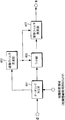
- FIG. 10 is a block diagram showing a configuration of the precoding unit 105.
- the transmission symbol vector d is input to the THP unit 201, and the THP unit 201 performs interference suppression processing based on the propagation path matrix H and the linear filter W calculated in the linear filter generation unit 203.
- An output signal of the THP unit 201 is input to the linear filter multiplication unit 205, multiplication of the linear filter W and power normalization are performed, and a transmission signal vector s is output from the precoding unit 105.
- the signal processing in the precoding unit 105 will be described.
- [•] T represents a transposition operation.
- the propagation path information is ideally fed back from each mobile station apparatus to the base station apparatus and input to the precoding unit 105.
- the linear filter W is first calculated in the linear filter generation unit 203.
- the linear filter W is a linear filter in which HW is a lower triangular matrix with respect to the channel matrix H. W can be obtained from QR decomposition for H.
- the transmission signal vector s [s 1 ,..., S Nt ] T can be calculated.
- Equation (3) the transmission signal vector of Expression (3) is transmitted from the base station apparatus.
- Equation (4) is It can be expanded as follows.
- a i, j represents the i-th row and j-th column component of the lower triangular matrix RH .
- the first user can receive only his / her transmission symbol, but the transmission symbol of the first user gives interference to the reception signal of the second user. That is, the received signal of the u-th user includes transmission symbols of the first to (u-1) users as interference.
- the precoding unit 105 of the base station apparatus subtracts in advance the interference component observed in each mobile station apparatus by THP. For example, as a transmission signal to the second user, Shall be sent. Substituting x 2 expressed by Equation (6) in a portion of the d 2 of the formula (5), the second user without interference from the transmission symbol of the first user, only the transmission symbols d 2 of its own Can be received. Similarly, by subtracting the transmission symbols of the first to (u-1) users in advance from the transmission signal of the u-th user in advance, all users can communicate without interference. It becomes.
- FIG. 11 is a diagram expressing the processing of Expression (6) as a feedback filter.
- the tap coefficient of this feedback filter is determined depending on the propagation path matrix H, the feedback filter output may diverge depending on the state of the propagation path, which is the THP output signal x 2. This means that a huge amount of transmission power is required to transmit the message, which is unrealistic.
- FIG. 12 is a diagram illustrating a feedback filter to which a modulo operation is applied. As shown in FIG. 12, in THP, divergence of the THP output signal is suppressed by applying a modulo operation every time an interference signal is subtracted.
- FIG. 13 is a diagram illustrating the concept of the modulo operation Mod M (x).
- the modulo operation Mod M (x) is such that the output of a certain input x is larger than ⁇ M and less than or equal to M.
- M is referred to as a modulo width.
- the output is given by the following equation.
- z t, 2 is a complex number in which the real part and the imaginary part are integers, respectively, and is selected so that the real part and the imaginary part on the right side of Equation (7) are each greater than ⁇ M and less than or equal to M.
- the This z t, 2 is called an equivalent expression of the modulo operation.
- the input transmission symbol vector d is input to the THP unit 201.
- a THP output x as shown in the following equation is output from the THP unit 201.
- diag (A) represents a diagonal matrix having the diagonal components of the matrix A as elements.
- a ⁇ 1 represents an inverse matrix of the matrix A.
- I m represents an m ⁇ m unit matrix.
- ⁇ is a power normalization term for equalizing the power of the transmission symbol vector d that is an input signal of the precoding unit 105 and the output signal s of the linear filter multiplication unit 205, and is given by the following equation.
- tr (•) represents a matrix trace operation
- E [•] represents an ensemble average.
- the precoding unit 105 of the base station apparatus finally outputs the transmission signal vector s given by Equation (9).
- the output s of the precoding unit 105 is input to the radio transmission unit 107 of each corresponding transmission antenna.
- a baseband transmission signal is converted into a radio frequency (RF) transmission signal.
- the output signal of the wireless transmission unit 107 is transmitted from each transmission antenna.
- FIG. 14 is a block diagram showing the configuration of the mobile station apparatus.
- a signal received by the receiving antenna is input to the wireless reception unit 301, and the wireless reception unit 301 converts the signal into a baseband signal.
- the received signal converted into the baseband is given by the following equation.
- the received signal converted into the baseband is input to the propagation path compensation unit 303.
- the u-th user's propagation path compensator 303 divides the received signal by ⁇ a u, u and then applies the modulo operation.
- the modulo output of the u-th user is given by
- z r, u is an equivalent expression of the modulo operation applied at the receiver of the u th user. It becomes. Therefore, the output r u ⁇ of the propagation path compensation unit 303 is It becomes. Thereafter, the output of the propagation path compensation unit 303 is input to the data demodulation unit 305 and the channel decoding unit 307, and after data demodulation and channel decoding are applied, transmission data of each user is detected.
- MU-MIMO BLAST ZF-THP The base station apparatus configuration and the receiver configuration in the BLAST ZF-THP system are almost the same as those in FIGS. 9 and 14, respectively. The difference is signal processing in the precoding unit 105 in the base station apparatus. Hereinafter, only signal processing in the precoding unit 105 in the base station apparatus will be described.
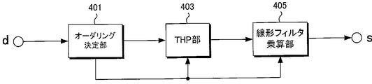
- FIG. 15 is a block diagram showing a configuration of the precoding unit 105 in the BLAST ZF-THP method.
- the transmission symbol vector d is first input to the ordering determination unit 401, and appropriate rearrangement, that is, ordering is performed by a method described later. Thereafter, the transmitted transmission symbol vector d p is input to the THP section 403, and THP processing is performed based on the linear filter and propagation path matrix determined by the ordering determination section 401.
- the output of the THP unit 403 is multiplied by a linear filter and a power normalization term in a linear filter multiplication unit 405 to generate a transmission signal vector s.
- the ordering determination unit 401 first calculates an inverse matrix H ⁇ 1 for the propagation path matrix H.
- the obtained inverse matrix H ⁇ 1 is defined as a linear filter W.
- W is composed of three column vectors ⁇ w 1 , w 2 , w 3 ⁇ .
- a column vector having the smallest norm is searched for and stored as w (1) .
- the element related to the second user having the smallest norm of the weight vector is deleted from the propagation path matrix H.
- the second row, which is the second user component, and the third row, which is the last row are interchanged. so that the transmitted symbols d 2 of the user is assigned.
- the ordering determination unit 401 calculates an inverse matrix H (2) -1 of the channel matrix H (2) for which the replacement has been performed, and sets it as a new linear filter W (2) .
- a column vector having the smallest norm is searched for among the column vectors constituting the linear filter W (2), and stored as w (2) .
- the number of vectors to search is (U-1).
- the column vector of the j-th column is the smallest.
- the element related to the jth user is deleted from the channel matrix.
- the propagation path matrix and the transmission symbol vector after replacement are H (3) and d (3) , respectively.
- the transmission signal vector d p that has been ordered and the linear filter W output from the ordering determination unit 401 are input to the THP unit 403. Similar to the THP unit 403 of the base station apparatus Precoding unit 105 in the MU-MIMO THP scheme, the THP unit 403 performs interference suppression processing by THP. After interference suppression is performed in the THP unit 403, the linear filter multiplication unit 405 performs multiplication of the linear filter W and power normalization to generate an output of the precoding unit 105.
- the above is the outline of the signal processing in the precoding unit 105 in the MU-MIMO BLAST ZF-THP system.
- repeated signal processing for the number of simultaneously accessed users is required for the precoding unit 105 of the base station apparatus, so that the amount of computation increases significantly in proportion to the increase in the number of users.
- the frequency utilization efficiency increases in proportion to the number of spatially multiplexed users, but in the BLAST ZF-THP scheme, the signal is proportional to the number of users. Since the amount of processing also increases significantly, the complexity of signal processing limits the amount of improvement in frequency utilization efficiency.
- FIG. 1 is a block diagram showing a configuration of a base station apparatus according to the first embodiment of the present invention. Signal processing in the base station apparatus will be described.
- the transmission data sequence of each user is subjected to channel coding in channel coding section 101, and then data modulated to QPSK, 16QAM, etc. in data modulation section 103. Thereafter, the transmission symbol of each user is input to the precoding unit 501.
- FIG. 2 is a block diagram showing a configuration of the precoding unit 501 according to the first embodiment of the present invention.
- the signal processing in the precoding unit 501 will be described.
- the transmission symbol vector d input first is input to the ordering determination unit 601.
- a transmission symbol vector d p obtained by multiplying an input d by a certain permutation matrix ⁇ is output from the ordering determination unit 601 as an already-ordered transmission symbol vector.
- d p is given by the following equation.
- the permutation matrix is a matrix in which columns (or rows) of a certain matrix are exchanged.
- a cubic permutation matrix is: There are six ways.
- the permutation matrix to be multiplied depends on the desired ordering order. For example, in the case of the MU-MIMO BLAST ZF-THP method described in the background art, a permutation matrix corresponding to an already-ordered transmission signal vector determined by repetitive signal processing in the precoding unit 501 is selected, and the MU that does not perform ordering -In the MIMO THP method, the unit matrix is selected as the permutation matrix.
- a method of selecting a permutation matrix that is, an ordering method in the present invention will be described.
- the correlation between transmitting antennas In the case of a general cellular model, since the antenna height of the base station apparatus is sufficiently high, the surroundings of the antennas of the base station apparatus In this case, the correlation between the antennas of the base station apparatus depends on the positional relationship between the mobile station apparatus and the base station apparatus performing communication, and generally the base station apparatus and the mobile station apparatus It is known that the correlation between antennas is strong when the distance to is large, and the correlation between antennas is weak when the distance is short.
- Multiple users and base station equipment Since simultaneous communication is performed, signals transmitted to each user are affected by different correlations between antennas on the base station apparatus side, that is, transmission antenna correlation, where the i-th transmission of the base station apparatus is performed.
- a transmission correlation coefficient ⁇ (i, j, u) that affects a transmission signal addressed to the u-th user between the antenna and the j-th transmission antenna is defined by the following equation.
- the transmission correlation coefficients of the users are compared, and the ordering order is determined in ascending order of correlation values.
- the transmission correlation coefficient is estimated in each mobile station apparatus.
- FIG. 3 is a block diagram showing the configuration of the mobile station apparatus according to the first embodiment of the present invention.
- Correlation information estimation section 701 in each mobile station apparatus estimates transmission antenna correlation coefficient information observed in each mobile station apparatus.
- the correlation information estimation unit 701 can estimate correlation coefficient information using a reference signal sequence transmitted from the base station apparatus.
- the correlation information estimation unit 701 may estimate the correlation coefficient from the distance information from the base station apparatus.
- each mobile station apparatus may notify other information representing the spatial correlation instead of notifying the correlation coefficient information itself. For example, the distance information from the base station apparatus may be directly notified to the base station apparatus without estimating the correlation coefficient.
- the mobile station apparatus when the mobile station apparatus has a plurality of reception antennas, it is possible to transmit a plurality of streams from the base station apparatus to the mobile station apparatus, but the number of signal streams that can be received by the mobile station apparatus is Since it depends on the propagation path information including the number of reception antennas and the correlation between the antennas, the mobile station apparatus may notify the base station apparatus of information on the desired number of signal streams to notify the correlation coefficient information.
- Radio transmission section (transmission section) 702 sends the estimated correlation coefficient information to the transmission antenna, and the correlation coefficient information is transmitted to the base station apparatus.
- the base station apparatus obtains transmission correlation coefficient information by inputting the information notified from the correlation information estimation unit 701 of each mobile station apparatus to the correlation information acquisition unit 503 of the base station apparatus.
- the transmission correlation coefficient information notified from the mobile station apparatus may be used as it is, or the transmission correlation coefficient is estimated from other information indicating the spatial correlation notified from the mobile station apparatus. May be.
- correlation information acquisition section 503 estimates correlation coefficient information separately from other signals transmitted from the mobile station device (for example, transmission data signal of uplink (mobile station device ⁇ base station device)). Also good.
- the correlation information acquisition unit 503 inputs the obtained transmission correlation coefficient information to the precoding unit 501.
- the input transmission correlation coefficient information is input to the ordering determination unit 601.
- the ordering determination unit 601 selects a permutation matrix ⁇ that can replace transmission symbol vectors so that transmission symbols addressed to users with large transmission correlation coefficients are arranged.
- the transmission signal addressed to the user corresponding to d p, 1 is generated first, and the transmission signal addressed to the user corresponding to d p, U is generated last. That is, the transmission symbol addressed to the user having the largest correlation coefficient corresponds to d p, 1, and the transmission symbol addressed to the user having the smallest correlation coefficient corresponds to d p, U.
- the transmission correlation coefficient to be compared may be a correlation coefficient between adjacent transmission antennas, that is, ⁇ (i, i + 1, u) may be compared between users, or phases between transmission antennas of different combinations may be compared.
- the number of relationships may be compared between users.
- the order of ordering may be determined based on other information representing the spatial correlation instead of the correlation coefficient itself. For example, when information regarding the number of desired signal streams is notified, it is determined that the allowable number of signal streams is inversely proportional to the strength of spatial correlation, and the allowable number of signal streams is arranged from the transmission symbols addressed to the user with a small number.
- a good ordering sequence The permutation matrix ⁇ determined by the ordering determination unit 601 is also input to the linear filter generation unit 603.
- the ordering order is determined based on the correlation information.
- determining the ordering order also determines the antenna port.
- MU-MIMO that performs precoding only performs signal processing on a transmission signal for which an antenna port used for transmission has already been determined. Therefore, it can be said that the present invention for determining the ordering order based on the correlation information determines the antenna port to be used according to the correlation coefficient. Therefore, the present invention can also be realized by controlling control information for controlling the antenna port to be used.
- the linear filter generation unit 603 calculates the linear filter W.
- a linear filter W that converts H ′ into a lower triangular matrix is calculated.
- Q ′ is a linear filter.
- a linear filter W Shall be used as a linear filter W.
- Q ′ itself may be used as a linear filter without making the reception quality of each user constant.
- a linear filter calculated based on a minimum mean square error (MMSE) standard that minimizes the mean square error (MSE) between the transmission signal and the reception signal may be used.
- MMSE minimum mean square error
- the linear filter W and the equivalent channel matrix H ′ calculated by the linear filter generation unit 603 are input to the THP unit 605 and the linear filter multiplication unit 607.
- the THP unit 605 performs THP processing on the transmission symbol vector d p that has been ordered input from the ordering determination unit 601 based on the linear filter W and the equivalent channel matrix H ′ input from the linear filter generation unit 603. Applies.
- the output x of the THP unit 605 is given by the following equation.
- the output x of the THP unit 605 is then input to the linear filter multiplication unit 607, which is multiplied by the linear filter W and the power normalization term ⁇ to calculate the output s of the precoding unit 501.
- the output s of the precoding unit 501 is given by the following equation.
- the output of the precoding unit 501 is then input to the radio transmission unit 107 of each corresponding transmission antenna.
- the wireless transmission unit 107 the baseband signal is converted into a radio frequency (RF) band signal.
- RF radio frequency
- the signal received by the reception antenna is input to the radio reception unit (reception unit) 703, and is converted into a baseband signal by the radio reception unit 703.
- the received signal converted into the baseband is given by the following equation.
- the received signal represented by Expression (28) is input to the propagation path compensation unit 707 of the mobile station apparatus, and the power normalization term ⁇ is divided. further and Therefore, the received signal after the power normalization term ⁇ is divided is expressed by the following equation.
- the propagation path compensation unit 707 applies a modulo operation to the received signal after the power normalization term ⁇ is divided, and calculates the output r ⁇ of the propagation path compensation unit 707.
- the modulo calculation in the propagation path compensation unit 707 may not be performed for the user whose transmission symbol is ordered at the head of the transmission symbol vector. The presence / absence of the modulo calculation is controlled by control information notified from the base station apparatus.
- the output r ⁇ of the propagation path compensation unit 707 is expressed by the following equation.
- z r is an equivalent expression of the modulo operation applied at the receiver, and the inverse matrix ⁇ ⁇ 1 of the permutation matrix ⁇ has only 0 or 1 in each element, and the determinant is also 1. It becomes. Therefore, the output r ⁇ of the propagation path compensation unit 707 is It becomes. Thereafter, the output r ⁇ of the propagation path compensation unit 707 is input to the data demodulation unit 305 and the channel decoding unit 307, and after data demodulation and channel decoding are applied, transmission data of each user is detected.
- the conventional MU- Unlike the MIMO BLAST ZF-THP method, it does not require repetitive processing, so even if the number of users increases significantly, the increase in the calculation amount of the base station device can be negligible. Can contribute to a significant reduction.
- the frequency utilization efficiency is greatly improved in proportion to the number of users. Therefore, the present invention capable of spatially multiplexing a large number of users with a small amount of calculation greatly improves the transmission speed of the entire system. Can also contribute.
- the first embodiment is intended for a case where all users perform nonlinear interference suppression by THP.
- an interference component to be subtracted for example, the second term of Equation (6)
- the interference component to be calculated also increases, resulting in an increase in the amount of calculation.
- the second embodiment in order to reduce the amount of calculation required for the calculation of the interference component, a case where a user who does not perform nonlinear interference suppression by THP and a user who performs it are mixed is targeted.
- N r 1
- downlink between a plurality of mobile station apparatuses having one or more reception antennas and a base station apparatus is performed.
- the present invention can also be applied to MU-MIMO transmission.
- the base station apparatus configuration and mobile station apparatus configuration in the second embodiment are almost equivalent to those in FIGS.
- the difference is that the signal processing in the precoding unit 501 of the base station apparatus and the propagation path compensation unit 707 of the mobile station apparatus are different.
- signal processing in the precoding unit 501 of the base station apparatus will be described.
- the ordering determination unit 601 of the precoding unit 501 determines the ordering order based on the transmission antenna correlation coefficient, and selects the permutation matrix ⁇ ⁇ corresponding to the determined ordering order, as in the first embodiment.
- the transmission symbol vector d is multiplied.
- the linear filter W is calculated as in the first embodiment.
- the transmission symbol vector d p ordered by the ordering determination unit 601 is input to the THP unit 605, and interference suppression is performed.
- the THP unit 605 performs interference suppression for all users.
- all users do not perform THP interference suppression, and the first to Kth users calculate a new linear filter W 1 in the linear filter generation unit 603. Then, interference suppression is performed, and only the remaining K + 1th user to Uth user perform interference suppression by THP based on the linear filter W 0 that converts the propagation path matrix into a lower triangular matrix.
- a method for calculating the linear filter W 1 in the linear filter generation unit 603 will be described.
- a calculation method based on the ZF standard that completely suppresses interference from other users will be described, but a linear filter based on the MMSE standard may be used.
- the Hermitian transposed matrix R ′ H of the upper triangular matrix R ′ obtained by applying QR decomposition to (H ′) H will be expressed using a partial matrix as shown in the following equation.
- the received signals of the users ordered from the first row to the K-th row of d p are not subject to any interference from other users, but are arranged after the (K + 1) -th row. It can be seen that the received signal of the user received interference from the transmission signal addressed to other users.
- THP section 605 of Precoding section 501 of the base station apparatus performs interference suppression by THP only for transmission symbols ordered after d p (K + 1) -th row.
- the output signal x of the THP unit 605 subjected to such interference suppression is input to the linear filter multiplication unit 607, multiplied by the linear filter W 0 , the linear filter W 1, and the power normalization term ⁇ , and output from the precoding unit 501.
- a signal s is generated. Since the signal processing in the base station apparatus other than the precoding unit 501 is the same as that in the first embodiment, description thereof is omitted.
- the configuration of the mobile station apparatus is almost equivalent to that in FIG. 3, and the signal processing in the propagation path compensation unit 707 is different.
- the propagation path compensation unit 707 performs division of the power normalization term on the received signal and then performs a modulo operation.
- the modulo calculation in the propagation path compensation unit 707 may not be performed. The presence / absence of the modulo calculation is controlled by control information notified from the base station apparatus.
- the ordering order determined in the precoding unit 501 of the base station apparatus depends on the transmission correlation coefficient observed in each mobile station apparatus, and the transmission symbols destined for the mobile station apparatus having a larger transmission correlation coefficient indicate the ordering order. Has a very high probability of being near the beginning. Therefore, the propagation path compensation unit 707 of the mobile station apparatus does not always perform the modulo calculation when the correlation coefficient is large based on the correlation coefficient information obtained by the correlation information estimation unit 701 of the mobile station apparatus. When the number of relations is small, it may be controlled to always perform a modulo calculation. Since the signal processing in the mobile station apparatus is the same as that of the first embodiment except for the signal processing in the propagation path compensation unit 707, description thereof is omitted.
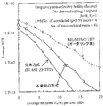
- FIG. 5 is a diagram illustrating an example of the BER characteristic achieved by the second embodiment of the present invention.
- the transmission conditions are the same as those in FIG. 4 shown in the first embodiment, and the number of users K for which interference suppression is performed only by the linear filter in the second embodiment is 4.
- BER 10 ⁇ 2 is achieved while reducing the amount of calculation compared to the case where interference suppression of all users is performed by THP (that is, the first embodiment). It can be seen that the required E b / N 0 degradation can be suppressed to about 2 dB.
- downlink MU-MIMO transmission is performed with a smaller amount of computation than in the first embodiment by not performing interference suppression by THP for all users but only for some users. It becomes possible.
- a mobile station apparatus that receives a transmission signal for which interference suppression is performed only by a linear filter does not require a modulo calculation
- a mobile station apparatus that does not have a modulo calculation function is replaced with a mobile station apparatus that has a modulo calculation function. It is also possible to make spatial multiplexing.
- the ordering in the precoding unit 501 of the base station apparatus is not performed based only on the transmission correlation coefficient, but also by using the conventional MU-MIMO BLAST ZF-THP method in combination. Intended for minimizing degradation of characteristics.
- the base station apparatus configuration in the third embodiment is almost the same as that in the first and second embodiments.
- the difference is signal processing in the ordering determination unit 601 in the precoding unit 501 of the base station apparatus.
- the signal processing in the ordering determination unit 601 will be described.
- the ordering determination unit 601 performs ordering for a certain number of users L based on the same method as the signal processing performed in the BLAST ZF-THP ordering determination unit 601 first. Thereafter, for (UL) users whose ordering order has not yet been determined, as in the first embodiment, ordering is performed based only on the transmission antenna correlation coefficient observed in the mobile station apparatus of each user.
- the transmission symbol vector d p to which the ordering is applied is expressed as follows: First half [d p, 1, ..., d p, U-L] of the transmitted symbol vector for T, the ordering sequence is determined only by the transmission correlation coefficient information, second half [d p, U-L + 1, ..., For d p, U ] T , the ordering order is determined by the MU-MIMO BLAST ZF-THP method. Therefore, in the third embodiment, unlike the first and second embodiments, the ordering determination unit 601 requires repeated signal processing for the number L of users whose ordering is determined by the MU-MIMO BLAST ZF-THP method. Is done.
- the precoding unit 501 of the base station apparatus adaptively sets the value of L so that desired transmission characteristics and calculation amount can be achieved according to the transmission correlation coefficient information notified from each mobile station apparatus and the propagation path matrix H. To change.
- the THP unit 605 does not perform interference suppression for a certain number of users K, and the interference suppression is performed only by a linear filter, thereby reducing the amount of calculation. Is possible.
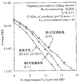
- FIG. 6 is a diagram illustrating an example of the BER characteristic achieved by the third embodiment of the present invention.
- the conditions are the same as those in FIG. 4 shown in the first embodiment.
- the best transmission characteristics are always improved according to the propagation path condition by combining the ordering method performed only by the transmission correlation coefficient and the ordering method performed by the MU-MIMO BLAST ZF-THP method. It is possible to obtain an effect and a calculation amount reduction effect.
- the first, second, and third embodiments are intended for narrowband single carrier transmission.
- the next generation mobile radio communication system for example, the fourth generation mobile radio communication system
- it is required to realize an ultra high transmission rate.
- it is essential to increase the communication bandwidth.
- multi-carrier-based access systems such as orthogonal frequency division multiple access (OFDMA) transmission system and multi-carrier code division multiple access (MC-CDMA) transmission system are studied.
- OFDMMA orthogonal frequency division multiple access
- MC-CDMA multi-carrier code division multiple access
- the fourth embodiment is directed to OFDM transmission, which is a type of multicarrier transmission.
- OFDM transmission is a method of performing parallel transmission by assigning a plurality of different frequencies (referred to as subcarriers) to a plurality of transmission symbols.
- the subcarrier frequency is selected such that transmission symbols transmitted in parallel do not interfere with each other and the maximum frequency utilization efficiency can be achieved.
- OFDM signals that can be parallel transmission of N c transmit symbols by N c pieces of optimum sub-carrier is generated by inverse fast discrete Fourier transform of N c points (IFFT).
- IFFT inverse fast discrete Fourier transform of N c points
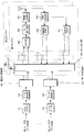
- FIG. 7 is a block diagram showing a base station apparatus configuration according to the fourth embodiment of the present invention.
- the number of antennas and the like are the same as those in the first embodiment.
- the transmission data addressed to each user is input to the channel coding unit 101 and the data modulation unit 103, and then input to the serial / parallel conversion unit 801 to be converted into parallel data. Transmission symbols converted in parallel are transmitted using respective subcarriers. Signal processing for transmission symbols transmitted by the k-th subcarrier will be described.
- the transmission symbol of the kth subcarrier of each user is input to the precoding unit 803 in the kth subcarrier, and the transmission signal of each transmission antenna transmitted by the kth subcarrier is calculated.
- the configuration of the precoding unit 803 is the same as that shown in FIG. 2, and the transmission signal vector, the propagation path matrix, the correlation coefficient information, and the generated linear filter matrix are associated with each subcarrier. It will be a thing. However, since the correlation coefficient information has almost the same value for all subcarriers unless the frequency is significantly different, the permutation matrix selected by the ordering determination unit 601 should be the same for all subcarriers. Is possible. In the conventional BLAST ZF-THP method, since the ordering order is different for each subcarrier, the amount of computation required for ordering determination increases greatly in proportion to the number of subcarriers. The amount of calculation required for determination does not depend on the number of subcarriers.
- the output of the precoding unit 803 of each subcarrier is input to the IFFT unit 805 of the corresponding transmission antenna.
- IFFT section 805 IFFT processing is applied using all input subcarrier components, and an OFDM transmission signal is generated.
- the generated OFDM signal is input to the GI insertion unit 807, and after a guard interval (GI) is inserted, it is input to the radio transmission unit 107 of each transmission antenna, and converted from a baseband signal to an RF band signal. Is done.
- the RF-band converted transmission signal is transmitted from each transmission antenna to a plurality of mobile station apparatuses.
- FIG. 8 is a block diagram showing a configuration of a mobile station apparatus according to the fourth embodiment of the present invention.
- the received signal is input to the wireless reception unit 703, and the RF band signal is converted into a baseband signal.
- the signal converted into the baseband is input to the GI removing unit 901, and after the GI is removed, the signal is input to the FFT unit 903, and the FFT processing with the same number of points as the IFFT processing in the IFFT unit 805 of the base station apparatus is performed. Done and decomposed into subcarrier components.
- the received signal decomposed into the subcarrier components is input to the propagation path compensation unit 909 corresponding to each subcarrier, and the propagation path compensation, that is, the division of the power normalization term and the modulo operation are performed as in the first embodiment. Applied.
- the output of the propagation path compensation unit 909 is input to the parallel / serial conversion unit 911, and after parallel / serial conversion, is input to the data demodulation unit 305 and the channel decoding unit 307, where data demodulation and channel decoding are performed. Transmission data transmitted from the station apparatus is detected.
- OFDM transmission is targeted.
- the conventional MU-MIMO BLASTAZF-THP method is applied to OFDM transmission, since different subcarriers must be ordered, the amount of computation increases significantly in proportion to the number of subcarriers.
- the ordering can be common to all subcarriers, the calculation amount does not depend on the number of subcarriers. Therefore, the amount of calculation can be greatly reduced as compared with the conventional method.
- the present invention is intended for multi-carrier transmission, the same ordering order can be applied to all frequencies even when the present invention is applied to single-carrier transmission that performs frequency division multiplexing, for example.
- the program that operates in the mobile station apparatus and the base station apparatus related to the present invention is a program (a program that causes a computer to function) that controls the CPU and the like so as to realize the functions of the above-described embodiments related to the present invention.
- Information handled by these devices is temporarily stored in the RAM at the time of processing, then stored in various ROMs and HDDs, read out by the CPU, and corrected and written as necessary.
- a recording medium for storing the program a semiconductor medium (for example, ROM, nonvolatile memory card, etc.), an optical recording medium (for example, DVD, MO, MD, CD, BD, etc.), a magnetic recording medium (for example, magnetic tape, Any of a flexible disk etc. may be sufficient.
- the processing is performed in cooperation with the operating system or other application programs.
- the functions of the invention may be realized.
- the program when distributing to the market, can be stored and distributed on a portable recording medium, or transferred to a server computer connected via a network such as the Internet.
- the storage device of the server computer is also included in the present invention.
- LSI which is typically an integrated circuit.
- Each functional block of the mobile station apparatus and the base station apparatus may be individually made into a processor, or a part or all of them may be integrated into a processor.
- the method of circuit integration is not limited to LSI, and may be realized by a dedicated circuit or a general-purpose processor.
- an integrated circuit based on the technology can also be used.
Landscapes
- Engineering & Computer Science (AREA)
- Computer Networks & Wireless Communication (AREA)
- Signal Processing (AREA)
- Physics & Mathematics (AREA)
- Spectroscopy & Molecular Physics (AREA)
- Mobile Radio Communication Systems (AREA)
- Radio Transmission System (AREA)
Priority Applications (1)
| Application Number | Priority Date | Filing Date | Title |
|---|---|---|---|
| US13/700,754 US9185577B2 (en) | 2010-05-31 | 2011-05-13 | Transmission apparatus, reception apparatus, wireless communication system, control program and integrated circuit |
Applications Claiming Priority (2)
| Application Number | Priority Date | Filing Date | Title |
|---|---|---|---|
| JP2010-125305 | 2010-05-31 | ||
| JP2010125305A JP5546357B2 (ja) | 2010-05-31 | 2010-05-31 | 送信装置、受信装置、無線通信システム、制御プログラムおよび集積回路 |
Publications (1)
| Publication Number | Publication Date |
|---|---|
| WO2011152186A1 true WO2011152186A1 (ja) | 2011-12-08 |
Family
ID=45066567
Family Applications (1)
| Application Number | Title | Priority Date | Filing Date |
|---|---|---|---|
| PCT/JP2011/061035 Ceased WO2011152186A1 (ja) | 2010-05-31 | 2011-05-13 | 送信装置、受信装置、無線通信システム、制御プログラムおよび集積回路 |
Country Status (3)
| Country | Link |
|---|---|
| US (1) | US9185577B2 (enExample) |
| JP (1) | JP5546357B2 (enExample) |
| WO (1) | WO2011152186A1 (enExample) |
Families Citing this family (5)
| Publication number | Priority date | Publication date | Assignee | Title |
|---|---|---|---|---|
| JP5975279B2 (ja) * | 2012-08-27 | 2016-08-23 | 国立大学法人九州工業大学 | プリコーディング装置およびプリコーディング方法並びにプリコーディング処理プログラム |
| EP3657691A1 (en) | 2013-03-15 | 2020-05-27 | InterDigital Patent Holdings, Inc. | Station and access point for non-linear precoding based multiuser multiple input multiple output |
| KR101616636B1 (ko) * | 2014-10-16 | 2016-04-28 | 영남대학교 산학협력단 | 듀얼 모드 빔포밍 방법 및 장치 |
| CN108683440A (zh) * | 2018-05-21 | 2018-10-19 | 重庆大学 | 一种高速移动下基于贪婪算法改进的模代数预编码方法 |
| CN109067444A (zh) * | 2018-09-20 | 2018-12-21 | 重庆大学 | 高速移动场景下基于用户调度改进的模代数预编码算法 |
Citations (2)
| Publication number | Priority date | Publication date | Assignee | Title |
|---|---|---|---|---|
| JP2009071825A (ja) * | 2007-09-11 | 2009-04-02 | Ntt Docomo Inc | コードブックに基づいたmimoシステムにおける適応プリコーディング方法及び装置 |
| JP2010028384A (ja) * | 2008-07-17 | 2010-02-04 | Toshiba Corp | 無線送信方法および装置 |
Family Cites Families (4)
| Publication number | Priority date | Publication date | Assignee | Title |
|---|---|---|---|---|
| US20090086860A1 (en) * | 2005-08-18 | 2009-04-02 | Mitsubishi Electric Corporation | Receiver apparatus |
| US7630337B2 (en) * | 2005-09-21 | 2009-12-08 | Broadcom Corporation | Method and system for an improved user group selection scheme with finite-rate channel state information feedback for FDD multiuser MIMO downlink transmission |
| US7894505B2 (en) * | 2006-04-19 | 2011-02-22 | Samsung Electronics Co., Ltd. | Apparatus and method for selecting effective channel in a multi-user MIMO system |
| US8451944B2 (en) * | 2009-09-04 | 2013-05-28 | Hitachi, Ltd. | Tomlinson harashima precoding with additional receiver processing in a multi-user multiple-input multiple-output wireless transmission system |
-
2010
- 2010-05-31 JP JP2010125305A patent/JP5546357B2/ja not_active Expired - Fee Related
-
2011
- 2011-05-13 US US13/700,754 patent/US9185577B2/en active Active
- 2011-05-13 WO PCT/JP2011/061035 patent/WO2011152186A1/ja not_active Ceased
Patent Citations (2)
| Publication number | Priority date | Publication date | Assignee | Title |
|---|---|---|---|---|
| JP2009071825A (ja) * | 2007-09-11 | 2009-04-02 | Ntt Docomo Inc | コードブックに基づいたmimoシステムにおける適応プリコーディング方法及び装置 |
| JP2010028384A (ja) * | 2008-07-17 | 2010-02-04 | Toshiba Corp | 無線送信方法および装置 |
Non-Patent Citations (3)
| Title |
|---|
| HIROSHI NAKANO ET AL.: "Adaptive THP Scheme Control for Downlink MU-MIMO Systems", IEICE TECHNICAL REPORT, vol. 109, no. 440, 24 February 2010 (2010-02-24), pages 203 - 208 * |
| JIA LIU ET AL.: "Improved Tomlinson-Harashima Precoding for the Downlink of Multiple Antenna Multi-User Systems", IEEE COMMUNICATIONS SOCIETY WCNC 2005, 7 March 2005 (2005-03-07), pages 466 - 472 * |
| YUNJIAN JIA ET AL.: "A Study on Control Information Transmission for Multiuser MIMO", 2010 NEN THE INSTITUTE OF ELECTRONICS, INFORMATION AND COMMUNICATION ENGINEERS SOGO TAIKAI KOEN RONBUNSHU TSUSHIN 1, vol. B-5-63, 2 March 2010 (2010-03-02), pages 495 * |
Also Published As
| Publication number | Publication date |
|---|---|
| US9185577B2 (en) | 2015-11-10 |
| US20130136050A1 (en) | 2013-05-30 |
| JP2011254183A (ja) | 2011-12-15 |
| JP5546357B2 (ja) | 2014-07-09 |
Similar Documents
| Publication | Publication Date | Title |
|---|---|---|
| US9008166B2 (en) | Filter calculating device, transmitting device, receiving device, processor, and filter calculating method | |
| JP5804594B2 (ja) | プリコーディング装置、プリコーディング用プログラムおよび集積回路 | |
| US9209874B2 (en) | Wireless transmission apparatus, wireless reception apparatus, wireless communication system, control program and integrated circuit | |
| JP5406987B2 (ja) | マルチユーザーマルチ入力マルチ出力無線送信システムにおける付加的受信機処理によるトムリンソン−原島プリコーディング | |
| JP5908307B2 (ja) | プリコーディング装置、無線送信装置、無線受信装置、無線通信システムおよび集積回路 | |
| JP5547988B2 (ja) | 通信システム、送信装置、受信装置、通信方法 | |
| WO2012121153A1 (ja) | 無線通信システム、基地局装置及び端末装置 | |
| JP2012100098A (ja) | 基地局装置、移動局装置及びそれらを用いた無線通信システム | |
| JPWO2014069262A1 (ja) | 基地局装置、端末装置および無線通信システム | |
| JP5546357B2 (ja) | 送信装置、受信装置、無線通信システム、制御プログラムおよび集積回路 | |
| JPWO2010150313A1 (ja) | 通信装置 | |
| JP5859913B2 (ja) | 無線受信装置、無線送信装置、無線通信システム、プログラムおよび集積回路 | |
| US20140369397A1 (en) | Communication device, communication method, communication program, processor, and communication system | |
| WO2012157393A1 (ja) | 基地局装置、移動局装置、制御プログラムおよび集積回路 | |
| US8976881B2 (en) | Wireless receiving apparatus and program | |
| JP5641787B2 (ja) | 端末装置及びそれを用いた無線通信システム | |
| KR20110079755A (ko) | 멀티 유저 mimo 시스템, 수신 장치 및 송신 장치 | |
| WO2014122850A1 (ja) | 基地局装置、プリコーディング方法、集積回路、無線通信システム | |
| JP2015056690A (ja) | 端末装置および受信装置 | |
| Ruder et al. | Combined user pairing and spectrum allocation for multiuser SC-FDMA transmission | |
| JP6047744B2 (ja) | 無線通信システム、無線通信装置および無線通信方法 | |
| JP2012070172A (ja) | 送信装置、受信装置、無線通信システム、制御プログラムおよび集積回路 | |
| JP5753041B2 (ja) | 無線送信装置、無線受信装置、および無線通信システム | |
| JP2013162331A (ja) | 無線送信装置、無線受信装置、無線通信システムおよびプリコーディング方法 | |
| JP2012015963A (ja) | 端末装置、基地局装置及びそれらを用いた無線通信システム |
Legal Events
| Date | Code | Title | Description |
|---|---|---|---|
| 121 | Ep: the epo has been informed by wipo that ep was designated in this application |
Ref document number: 11789595 Country of ref document: EP Kind code of ref document: A1 |
|
| NENP | Non-entry into the national phase |
Ref country code: DE |
|
| WWE | Wipo information: entry into national phase |
Ref document number: 13700754 Country of ref document: US |
|
| 122 | Ep: pct application non-entry in european phase |
Ref document number: 11789595 Country of ref document: EP Kind code of ref document: A1 |