WO2011152023A1 - 端末装置 - Google Patents
端末装置 Download PDFInfo
- Publication number
- WO2011152023A1 WO2011152023A1 PCT/JP2011/003014 JP2011003014W WO2011152023A1 WO 2011152023 A1 WO2011152023 A1 WO 2011152023A1 JP 2011003014 W JP2011003014 W JP 2011003014W WO 2011152023 A1 WO2011152023 A1 WO 2011152023A1
- Authority
- WO
- WIPO (PCT)
- Prior art keywords
- vehicle
- unit
- road
- terminal device
- data
- Prior art date
- Legal status (The legal status is an assumption and is not a legal conclusion. Google has not performed a legal analysis and makes no representation as to the accuracy of the status listed.)
- Ceased
Links
Images





Classifications
-
- G—PHYSICS
- G08—SIGNALLING
- G08G—TRAFFIC CONTROL SYSTEMS
- G08G1/00—Traffic control systems for road vehicles
- G08G1/01—Detecting movement of traffic to be counted or controlled
- G08G1/0104—Measuring and analyzing of parameters relative to traffic conditions
-
- G—PHYSICS
- G01—MEASURING; TESTING
- G01C—MEASURING DISTANCES, LEVELS OR BEARINGS; SURVEYING; NAVIGATION; GYROSCOPIC INSTRUMENTS; PHOTOGRAMMETRY OR VIDEOGRAMMETRY
- G01C21/00—Navigation; Navigational instruments not provided for in groups G01C1/00 - G01C19/00
- G01C21/26—Navigation; Navigational instruments not provided for in groups G01C1/00 - G01C19/00 specially adapted for navigation in a road network
- G01C21/34—Route searching; Route guidance
- G01C21/36—Input/output arrangements for on-board computers
- G01C21/3691—Retrieval, searching and output of information related to real-time traffic, weather, or environmental conditions
Definitions
- the present invention relates to a technique for determining whether or not there is a traffic jam in an in-vehicle terminal device.
- Road-to-vehicle communication is being studied to prevent collisions at intersections.
- information on the situation of the intersection is communicated between the roadside device and the vehicle-mounted device.
- Road-to-vehicle communication requires the installation of roadside equipment, which increases labor and cost.
- ITS Intelligent Transport Systems
- ITS Intelligent Transport Systems
- each vehicle-mounted device may receive information on several tens to several hundreds of other vehicles, resulting in a huge amount of communication traffic. Therefore, it is required to reduce the amount of transmission data by thinning out unnecessary data while leaving only useful information for traffic jam determination in each on-vehicle device.
- the present invention has been made in view of such circumstances, and an object of the present invention is to provide a terminal device suitable for determining the presence or absence of traffic congestion based on inter-vehicle communication.
- an aspect of the present invention is a terminal device mounted on a vehicle for performing vehicle-to-vehicle communication, as identification information for each section set in advance for at least some roads.
- the vehicle data of the host vehicle including the road ID and the traveling speed during traveling are transmitted.
- communication traffic between vehicles can be reduced in a terminal device that determines the presence or absence of traffic congestion based on vehicle-to-vehicle communication.
- FIGS. 3A to 3D are diagrams showing frame formats defined in the communication system. It is a figure which shows the structure of a sub-frame.
- FIGS. 5A and 5B are diagrams showing the format of a MAC frame stored in a packet signal defined in the communication system. It is a figure which shows the structure of the terminal device mounted in the vehicle. It is a figure which shows an example of the map data to which road ID was provided. It is a figure which shows the structure of the terminal device which concerns on this embodiment.
- FIG. It is a flowchart of the inter-vehicle communication process which concerns on this embodiment. It is a flowchart of the traffic judgment process in a traffic judgment part.
- the terminal device broadcasts a packet signal storing information such as the speed and position of the vehicle (hereinafter referred to as “data”). Further, the other terminal device receives the packet signal and recognizes the approach of the vehicle based on the data. Further, as road-to-vehicle communication, the base station apparatus repeatedly defines a frame including a plurality of subframes. The base station apparatus selects any one of the plurality of subframes, and broadcasts a packet signal in which control information and the like are stored in the period of the head portion of the selected subframe.
- the control information includes information related to a period (hereinafter referred to as “road vehicle transmission period”) for the base station apparatus to broadcast the packet signal.
- the terminal device specifies a road and vehicle transmission period based on the control information, and transmits a packet signal in a period other than the road and vehicle transmission period.
- the collision probability of packet signals between them is reduced. That is, when the terminal device recognizes the content of the control information, interference between road-vehicle communication and vehicle-to-vehicle communication is reduced.
- the area where the terminal device performing inter-vehicle communication is mainly classified into three types.
- first area One is an area formed around the base station apparatus (hereinafter referred to as “first area”), and the other is an area formed outside the first area (hereinafter referred to as “second area”). Another one is an area formed outside the second area (hereinafter referred to as “outside the second area”).
- first area and the second area the terminal device can receive the packet signal from the base station apparatus with a certain quality, whereas outside the second area, the packet signal from the base station apparatus is received.
- the terminal device cannot receive with a certain quality.
- the first area is formed closer to the center of the intersection than the second area. Since the vehicle existing in the first area is a vehicle existing near the intersection, the packet signal from the terminal device mounted on the vehicle can be said to be important information from the viewpoint of suppressing collision accidents.
- a period for vehicle-to-vehicle communication (hereinafter referred to as “vehicle transmission period”) is formed by time division multiplexing of a priority period and a general period.
- the priority period is a period for use by a terminal apparatus existing in the first area, and the terminal apparatus transmits a packet signal in any of a plurality of slots forming the priority period.
- the general period is a period for use by a terminal apparatus existing in the second area, and the terminal apparatus transmits a packet signal by the CSMA method in the general period.
- the terminal device existing outside the second area transmits a packet signal by the CSMA method regardless of the frame configuration. Here, it is determined in which area the terminal device mounted on the vehicle is present.
- FIG. 1 shows a configuration of the communication system 100 as described above. This corresponds to a case where one intersection is viewed from above.
- the communication system 100 includes a base station device 10, a first vehicle 12a, a second vehicle 12b, a third vehicle 12c, a fourth vehicle 12d, a fifth vehicle 12e, a sixth vehicle 12f, and a seventh vehicle 12g, collectively referred to as a vehicle 12. , The eighth vehicle 12h, and the network 202.
- Each vehicle 12 is equipped with a terminal device (not shown).
- the first area 210 is formed around the base station apparatus 10, the second area 212 is formed outside the first area 210, and the second outside area 214 is formed outside the second area 212. ing.
- the road that goes in the horizontal direction of the drawing that is, the left and right direction
- intersects the vertical direction of the drawing that is, the road that goes in the up and down direction, at the central portion.
- the upper side of the drawing corresponds to the direction “north”
- the left side corresponds to the direction “west”
- the lower side corresponds to the direction “south”
- the right side corresponds to the direction “east”.
- the intersection of the two roads is an “intersection”.
- the first vehicle 12a and the second vehicle 12b are traveling from left to right
- the third vehicle 12c and the fourth vehicle 12d are traveling from right to left
- the fifth vehicle 12e and the sixth vehicle 12f are traveling from the top to the bottom
- the seventh vehicle 12g and the eighth vehicle 12h are traveling from the bottom to the top.
- the communication system 100 arranges the base station apparatus 10 at the intersection.
- the base station device 10 controls communication between terminal devices.
- the base station device 10 repeatedly generates a frame including a plurality of subframes based on a signal received from a GPS satellite (not shown) and a frame formed by another base station device 10 (not shown).
- the road vehicle transmission period can be set at the head of each subframe.
- the base station apparatus 10 selects a subframe in which the road and vehicle transmission period is not set by another base station apparatus 10 from among the plurality of subframes.
- the base station apparatus 10 sets a road and vehicle transmission period at the beginning of the selected subframe.
- the base station apparatus 10 stores control information including information on a road and vehicle transmission period in a packet signal.
- the base station apparatus 10 also stores predetermined data in the packet signal.
- the base station apparatus 10 notifies the packet signal in the set road and vehicle transmission period.
- a first area 210 and a second area 212 are formed around the communication system 100 according to the reception status when the terminal apparatus receives a packet signal from the base station apparatus 10.
- a first area 210 is formed in the vicinity of the base station apparatus 10 as an area having a relatively good reception status. It can be said that the first area 210 is formed near the central portion of the intersection.
- the second area 212 is formed outside the first area 210 as a region where the reception situation is worse than that of the first area 210.
- an area outside the second area 214 is formed as an area where the reception status is worse than that in the second area 212. Note that the packet signal error rate and received power are used as the reception status.
- the plurality of terminal apparatuses receive the packet signal broadcasted by the base station apparatus 10 and, based on the reception status of the received packet signal, in any of the first area 210, the second area 212, and the second outside area 214 Estimate if it exists.
- the terminal device When it is estimated that the data exists in the first area 210 or the second area 212, the terminal device generates a frame based on the control information included in the received packet signal. As a result, the frame generated in each of the plurality of terminal devices is synchronized with the frame generated in the base station device 10. Further, the terminal device recognizes the road and vehicle transmission period set by each base station device 10 and specifies the vehicle and vehicle transmission period for transmission of the packet signal.
- the terminal device transmits a packet signal by executing TDMA in the priority period and executing CSMA / CA in the general period.
- the terminal apparatus selects subframes having the same relative timing even in the next frame.
- the terminal device selects slots having the same relative timing in the next frame.
- the terminal device acquires data and stores the data in a packet signal.
- the data includes, for example, information related to the location.
- the terminal device also stores control information in the packet signal. That is, the control information transmitted from the base station device 10 is transferred by the terminal device.
- the terminal device transmits a packet signal by executing CSMA / CA regardless of the frame configuration.
- FIG. 2 shows the configuration of the base station apparatus 10.
- the base station apparatus 10 includes an antenna 20, an RF unit 22, a modem unit 24, a processing unit 26, a control unit 30, and a network communication unit 80.
- the RF unit 22 receives a packet signal from a terminal device (not shown) or another base station device 10 by the antenna 20 as a reception process.
- the RF unit 22 performs frequency conversion on the received radio frequency packet signal to generate a baseband packet signal.
- the RF unit 22 outputs a baseband packet signal to the modem unit 24.
- baseband packet signals are formed by in-phase and quadrature components, so two signal lines should be shown, but here only one signal line is shown for clarity. Shall be shown.
- the RF unit 22 also includes an LNA (Low Noise Amplifier), a mixer, an AGC, and an A / D conversion unit.
- LNA Low Noise Amplifier
- the RF unit 22 performs frequency conversion on the baseband packet signal input from the modem unit 24 as a transmission process, and generates a radio frequency packet signal. Further, the RF unit 22 transmits a radio frequency packet signal from the antenna 20 during the road-vehicle transmission period.
- the RF unit 22 also includes a PA (Power Amplifier), a mixer, and a D / A conversion unit.
- PA Power Amplifier
- the modem unit 24 demodulates the baseband packet signal from the RF unit 22 as a reception process. Further, the modem unit 24 outputs the demodulated result to the processing unit 26. The modem unit 24 also modulates the data from the processing unit 26 as a transmission process. Further, the modem unit 24 outputs the modulated result to the RF unit 22 as a baseband packet signal.
- the modem unit 24 since the communication system 100 corresponds to the OFDM (Orthogonal Frequency Division Multiplexing) modulation method, the modem unit 24 also executes FFT (Fast Fourier Transform) as reception processing and IFFT (Inverse TransFour) as transmission processing. Also execute.
- FFT Fast Fourier Transform
- IFFT Inverse TransFour
- the processing unit 26 receives a signal from a GPS satellite (not shown), and acquires time information based on the received signal.
- the processing unit 26 generates a plurality of frames based on the time information. For example, the processing unit 26 generates 10 frames of “100 msec” by dividing the period of “1 sec” into 10 on the basis of the timing indicated by the time information. By repeating such processing, the frame is defined to be repeated.
- the processing unit 26 may detect control information from the demodulation result. Such processing corresponds to generating a frame synchronized with the timing of the frame formed by another base station apparatus 10. Details of the processing of the processing unit 26 at that time will be described later.
- FIGS. 3A to 3D show frame formats defined in the communication system 100.
- FIG. FIG. 3A shows the structure of the frame.
- the frame is formed of N subframes indicated as the first subframe to the Nth subframe. For example, when the frame length is 100 msec and N is 10, a subframe having a length of 10 msec is defined.
- FIG. 3B shows a configuration of a frame generated by the first base station apparatus 10a.
- the first base station apparatus 10a sets a road and vehicle transmission period at the beginning of the first subframe.
- the 1st base station apparatus 10a sets a vehicle transmission period following the road and vehicle transmission period in a 1st sub-frame.
- the vehicle transmission period is a period during which the terminal device can notify the packet signal.
- the first base station apparatus 10a can notify the packet signal, and in the frame, the terminal apparatus transmits in the vehicle and vehicle transmission period other than the road and vehicle transmission period. It is defined that the packet signal can be broadcast. Furthermore, the first base station apparatus 10a sets only the vehicle transmission period from the second subframe to the Nth subframe.
- FIG. 3C shows a configuration of a frame generated by the second base station apparatus 10b.
- the second base station apparatus 10b sets a road and vehicle transmission period at the beginning of the second subframe.
- the second base station apparatus 10b sets the vehicle transmission period from the first stage of the road and vehicle transmission period in the second subframe, from the first subframe and the third subframe to the Nth subframe.
- FIG. 3D shows a configuration of a frame generated by the third base station apparatus 10c.
- the third base station apparatus 10c sets a road and vehicle transmission period at the beginning of the third subframe.
- the third base station apparatus 10c sets the vehicle transmission period from the first stage of the road and vehicle transmission period in the third subframe, the first subframe, the second subframe, and the fourth subframe to the Nth subframe.
- the plurality of base station apparatuses 10 select different subframes, and set the road and vehicle transmission period at the head portion of the selected subframe.
- FIG. 4 shows the structure of the subframe.
- one subframe is configured in the order of a road and vehicle transmission period, a priority period, and a general period.
- the priority period and the general period correspond to the vehicle transmission period shown in FIG.
- the subframe is configured in the order of the priority period and the general period.
- a plurality of slots are time-division multiplexed. With such a configuration, a frame including at least a plurality of slots is repeated.
- the processing unit 26 inputs a demodulation result from another base station device 10 or a terminal device (not shown) via the RF unit 22 and the modem unit 24.
- the configuration of the MAC frame stored in the packet signal will be described as a demodulation result.
- the MAC frame input to the processing unit 26 and the MAC frame output from the processing unit 26 have the same configuration.
- 5A and 5B show the format of a MAC frame stored in a packet signal defined in the communication system 100.
- FIG. FIG. 5A shows the format of the MAC frame.
- “MAC header”, “RSU control header”, “application data”, and “CRC” are arranged in order from the top.
- the RSU control header corresponds to the control information described above.
- the application data stores data to be notified to the terminal device such as accident information.
- FIG. 5B shows the format of the RSU control header.
- the RSU control header includes “basic information”, “timer value”, “transfer count”, “subframe number”, “frame period”, “used subframe number”, “start timing & time length” in order from the top. Deploy. Note that the configuration of the RSU control header is not limited to that shown in FIG. 5B, and some elements may be excluded, or other elements may be included.
- the number of times of transfer indicates the number of times that the control information transmitted from the base station apparatus 10, particularly the content of the RSU control header, has been transferred by a terminal device (not shown).
- the base station device 10 corresponds to the base station device 10 for the MAC frame output from the processing unit 26, and the base station device 10 corresponds to the MAC frame input to the processing unit 26. Corresponds to another base station apparatus 10. This is common in the following description.
- the MAC frame output from the processing unit 26 has the transfer count set to “0”. In addition, the number of transfers for the MAC frame input to the processing unit 26 is set to “0” or more.
- the number of subframes indicates the number of subframes forming one frame.
- the frame period indicates the period of the frame, and is set to, for example, “100 msec” as described above.
- the used subframe number is a number of a subframe in which the base station device 10 sets a vehicle transmission period. As shown in FIG. 3A, the subframe number is set to “1” at the head of the frame. In the start timing & time length, the start timing of the road and vehicle transmission period at the beginning of the subframe and the time length of the road and vehicle transmission period are indicated. Returning to FIG.
- the processing unit 26 generates a frame synchronized with the timing of a frame formed by another base station apparatus 10
- the processing unit 26 extracts a MAC frame whose transfer count is set to “0” from the MAC frames. This corresponds to a packet signal directly transmitted from another base station apparatus 10.
- the processing unit 26 specifies the value of the used subframe number among the extracted MAC frames. This corresponds to specifying a subframe used by another base station apparatus 10.
- the processing unit 26 measures the received power of the packet signal arranged at the head of the already identified subframe. This corresponds to measuring the reception power of the packet signal from the other base station apparatus 10.
- the processing unit 26 extracts a MAC frame whose transfer count is set to “1” or more from the MAC frames. This corresponds to a packet signal transmitted from the other base station apparatus 10 and then transferred by the terminal apparatus.
- the processing unit 26 specifies the value of the used subframe number among the extracted MAC frames. This corresponds to specifying a subframe used by another base station apparatus 10.
- the terminal device transfers the subframe number when the terminal device receives a packet signal from another base station device 10.
- the processing unit 26 also measures the received power of these packet signals. Further, the processing unit 26 estimates that the acquired received signal is the received power of the packet signal from the other base station apparatus 10 to which the control information is transferred by the packet signal.
- the processing unit 26 identifies a subframe in which a road and vehicle transmission period is to be set. Specifically, the processing unit 26 checks whether there is an “unused” subframe. If present, the processing unit 26 selects one of the “unused” subframes. Here, when a plurality of subframes are unused, the processing unit 26 selects one subframe at random. When there is no unused subframe, that is, when each of the plurality of subframes is used, the processing unit 26 preferentially specifies a subframe with low reception power.
- the processing unit 26 sets the road and vehicle transmission period at the top of the subframe of the identified subframe number.
- the processing unit 26 generates a MAC frame to be stored in the packet signal.
- the processing unit 26 determines the value of the RSU control header of the MAC frame according to the setting of the road and vehicle transmission period. This corresponds to control information related to the frame configuration.
- the processing unit 26 acquires predetermined information via the network communication unit 80 and includes the predetermined information in the application data.
- the network communication unit 80 is connected to a network 202 (not shown).
- the processing unit 26 broadcasts the packet signal to the modem unit 24 and the RF unit 22 during the road and vehicle transmission period.
- the packet signal includes control information and identification information for identifying the base station apparatus 10. Identification information for identifying the base station apparatus 10 is included in the MAC header of FIG.
- the processing unit 26 transmits the failure information to the network communication unit. Output to 80.
- the network communication unit 80 notifies failure information to a management center (not shown) via the network 202 (not shown). That is, the management center is notified of the failure found.
- the estimation result may be included in the packet signal and notified from the processing unit 26, the modem unit 24, and the RF unit 22.
- the control unit 30 controls processing of the entire base station apparatus 10.
- This configuration can be realized in terms of hardware by a CPU, memory, or other LSI of any computer, and in terms of software, it can be realized by a program loaded in the memory, but here it is realized by their cooperation.
- Draw functional blocks Therefore, those skilled in the art will understand that these functional blocks can be realized in various forms by hardware alone or a combination of hardware and software.
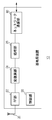
- FIG. 6 shows the configuration of the terminal device 14 mounted on the vehicle 12.
- the terminal device 14 includes an antenna 50, an RF unit 52, a modem unit 54, a processing unit 56, and a control unit 58.
- the processing unit 56 includes a generation unit 64, a timing identification unit 60, a transfer determination unit 90, a notification unit 70, an estimation unit 72, a storage unit 74, and a positioning unit 76.
- the timing specifying unit 60 includes an extraction unit 66, a selection unit 92, and a carrier sense unit 94.
- the antenna 50, the RF unit 52, and the modem unit 54 execute the same processing as the antenna 20, the RF unit 22, and the modem unit 24 in FIG. Therefore, here, the difference will be mainly described.
- the modem unit 54 and the processing unit 56 receive packet signals from other terminal devices 14 and the base station device 10 (not shown). As described above, a subframe in which the priority period and the general period are time-multiplexed is defined, and the road and vehicle transmission period may be time-multiplexed in the subframe.
- the road and vehicle transmission period is a period during which a packet signal can be notified from the base station apparatus 10.
- the modem unit 54 and the processing unit 56 receive the packet signal from the base station apparatus 10 in the road and vehicle transmission period.
- the packet signal includes identification information for identifying the base station apparatus 10 that is a notification source of the packet signal.
- the priority period is a period that the terminal apparatus 14 existing in the first area 210 formed around the base station apparatus 10 should use for broadcasting the packet signal.
- the general period is a period that the terminal device 14 existing in the second area formed outside the first area 210 should use for broadcasting the packet signal. Also, a frame in which a plurality of subframes are time-multiplexed is defined.
- the extraction unit 66 measures the received power of the packet signal from the base station apparatus 10. Based on the measured received power, the extraction unit 66 estimates whether it exists in the first area 210, the second area 212, or outside the second area 214. For example, the extraction unit 66 stores a first threshold for area determination and a second threshold for area determination. Here, the first threshold for area determination is defined to be larger than the second threshold for area determination. If the received power is greater than the first threshold value for area determination, the extraction unit 66 determines that it exists in the first area 210. If the received power is equal to or smaller than the first threshold for area determination and is larger than the second threshold for area determination, the extraction unit 66 determines that the second area 212 exists.
- the extraction unit 66 determines that the power is present outside the second area 212. Note that the extraction unit 66 may use an error rate instead of the received power, or may use a combination of the received power and the error rate.
- the extraction unit 66 determines any one of the priority period, the general period, and the timing unrelated to the frame configuration as the transmission period based on the estimation result. More specifically, when it is estimated that the extraction unit 66 exists outside the second area 214, the extraction unit 66 selects a timing unrelated to the frame configuration. When it is estimated that the extraction unit 66 exists in the second area 212, the extraction unit 66 selects the general period. When it is estimated that the extraction unit 66 exists in the first area 210, the extraction unit 66 selects a priority period.
- the extraction unit 66 specifies the timing of the subframe in which the road-vehicle transmission period is arranged. Further, the extraction unit 66 generates a frame based on the subframe timing and the content of the RSU control header. Note that the generation of the frame may be performed in the same manner as the processing unit 26 described above, and thus the description thereof is omitted here. As a result, the extraction unit 66 generates a frame synchronized with the frame formed in the base station apparatus 10. Moreover, the extraction part 66 specifies a road and vehicle transmission period based on the content of the RSU control header.
- the extraction unit 66 When the priority period is selected, the extraction unit 66 outputs information related to the priority period to the selection unit 92. When the general period is selected, the extraction unit 66 outputs information on the frame and subframe timing and the vehicle transmission period to the carrier sense unit 94. When selecting the timing irrelevant to the frame configuration, the extraction unit 66 instructs the carrier sense unit 94 to execute carrier sense.
- the selection unit 92 receives information on the priority period from the extraction unit 66. In addition, the selection unit 92 selects any slot from the plurality of slots included in the priority period, and determines the selected slot as the transmission timing. Here, received power may be used to select a slot. For example, a slot with a small reception power is selected.
- the selection unit 92 notifies the generation unit 64 of the determined transmission timing.
- the carrier sense unit 94 receives information on frame and subframe timing and vehicle transmission period from the extraction unit 66.
- the carrier sense unit 94 measures the interference power by performing carrier sense in the general period. Further, the carrier sense unit 94 determines the transmission timing in the general period based on the interference power. More specifically, the carrier sense unit 94 stores a predetermined threshold value in advance, and compares the interference power with the threshold value. If the interference power is smaller than the threshold value, the carrier sense unit 94 determines the transmission timing.
- the carrier sense unit 94 determines the transmission timing by executing the CSMA without considering the frame configuration. The carrier sense unit 94 notifies the generation unit 64 of the determined transmission timing.
- the positioning unit 76 includes a GPS receiver (not shown), a gyroscope, a vehicle speed sensor, and the like. Based on data supplied from the GPS receiver, the position of the vehicle 12 (not shown), that is, the vehicle 12 on which the terminal device 14 is mounted, Get direction, speed, etc. The existence position is indicated by latitude and longitude. Since a known technique may be used for these acquisitions, description thereof is omitted here.
- the positioning unit 76 outputs the presence position and the like to the generation unit 64.
- the generation unit 64 receives an existing position from the positioning unit 76.
- the generation unit 64 uses the MAC frame shown in FIGS. 5A to 5B and stores the presence position in the application data. Further, the generation unit 64 receives identification information from the extraction unit 66, and also stores the most recently received identification information in the application data.
- the generation unit 64 generates a packet signal including a MAC frame, and generates the packet signal via the modulation / demodulation unit 54, the RF unit 52, and the antenna 50 at the transmission timing determined by the selection unit 92 or the carrier sense unit 94. Broadcast packet signals.
- the transmission timing is included in the vehicle transmission period.
- the transfer determination unit 90 controls the transfer of the RSU control header.
- the extraction unit 66 extracts an RSU control header from a packet signal for which the base station device 10 is an information source. As described above, when the packet signal is transmitted directly from the base station apparatus 10, the number of transfers is set to “0”, but when the packet signal is transmitted from another terminal apparatus 14. The number of transfers is set to a value of “1 or more”. Here, since the used subframe number is not changed when transferred by the terminal apparatus 14, the subframe used in the base station apparatus 10 serving as the information source is specified by referring to the used subframe number.
- the transfer determination unit 90 acquires information on the number of transfers for each base station apparatus 10 that is an information source. More specifically, the transfer determining unit 90 sequentially acquires the number of transfers corresponding to the subframe number “1”, and then executes the same processing for the number of transfers corresponding to other subframe numbers. . Further, the transfer determination unit 90 acquires, for each base station device 10 serving as an information source, the smaller transfer number, for example, the value of the minimum transfer number, from the information related to the transfer number related to the base station device 10. To do. That is, the transfer count acquisition unit 110 acquires the minimum transfer count corresponding to the subframe number “1”, the minimum transfer count corresponding to the subframe number “2”, and the like.
- the transfer determination unit 90 measures the RSU control header, that is, the number of extractions of control information, for each base station apparatus 10 that is an information source. Moreover, the transfer determination part 90 selects the frequency
- the transfer determination unit 90 stores the subframe number, the transfer count, and the extraction count in association with each other. In addition, the transfer determination unit 90 updates the stored content when the number of transfers and the number of extractions are updated.
- the transfer determination unit 90 acquires the number of transfers and the number of extractions for each base station device 10.
- the transfer determination unit 90 selects control information corresponding to at least one base station apparatus 10 as control information to be transferred based on the number of transfers and the number of extractions. More specifically, the transfer determination unit 90 compares the number of transfers with the plurality of base station devices 10 and then compares the number of extractions. That is, after selecting the control information with the smaller number of transfers, for example, the control information with the minimum number of transfers, the control information with the larger number of extractions and the maximum number of extractions are selected from the selected control information. Selected control information is selected.
- control information having the minimum number of transfers and the control information having the maximum number of extractions corresponding to the number of transfers is selected by the transfer determination unit 90. It can be said that control information is received near the base station apparatus 10 which becomes an information source, so that the frequency
- the transfer determination unit 90 instructs the generation unit 64 to generate an RSU control header based on the selected control information.
- the transfer determination unit 90 increases the number of transfers in the information related to the number of transfers when storing the control information in the RSU control header.
- the generation unit 64 generates an RSU control header based on the control information selected by the transfer determination unit 90 and increases the number of transfers at that time.
- the storage unit 74 stores position information of the base station apparatus 10 that can broadcast a packet signal to be received by the RF unit 52, the modem unit 54, and the processing unit 56. Since a plurality of base station devices 10 are installed, the storage unit 74 stores a plurality of pieces of position information. The position information is indicated by latitude and longitude so as to be associated with the road map. Further, since the position information is shown as digital data, the storage unit 74 is configured as a storage medium such as a hard disk capable of storing digital data. Here, in order to simplify the description, it is assumed that the position information is stored in the storage unit 74 in advance. For example, it is preset when the terminal device 14 is purchased.
- the estimation unit 72 sequentially receives the positioning positions from the positioning unit 76.
- the estimation unit 72 assumes a circular area having a predetermined radius with the position information stored in the storage unit 74 as the center. Such a region corresponds to, for example, the first area 210 and the second area 212 in FIG. 1, but here corresponds to the second area.
- a circular area is assumed for each of the plurality of base station apparatuses 10.
- the estimation unit 72 is present in the vicinity of the base station apparatus 10 installed at the center of the circular area by detecting that the consecutively received existence positions have entered from the outside to the inside of the circular area. Detect that.
- the estimation part 72 detects whether the packet signal from the base station apparatus 10 is received while existing in the circular area.
- the estimation unit 72 estimates that the base station apparatus 10 is operating normally. On the other hand, when the packet signal is not received, the estimation unit 72 estimates a failure of the base station device 10. When the estimation unit 72 estimates a failure, the estimation unit 72 outputs the fact to the generation unit 64 and the notification unit 70.
- the generation unit 64 When the generation unit 64 receives the failure estimation result from the estimation unit 72, the generation unit 64 stores the failure estimation result in the application data. As a result, the failure estimation result is notified during the vehicle transmission period.
- the notification unit 70 acquires a packet signal from the base station device 10 (not shown) in the road and vehicle transmission period, and acquires a packet signal from another terminal device 14 (not shown) in the vehicle and vehicle transmission period.
- the notification unit 70 notifies the driver of the approach of another vehicle 12 (not shown) to the driver via a monitor or a speaker in accordance with the content of data stored in the packet signal. Furthermore, when the notification unit 70 receives the estimation result of the failure from the estimation unit 72, the notification unit 70 also notifies the driver of the estimation result.
- the notification unit 70 displays the display color of the part where the base station apparatus 10 that has failed is installed in red. Moreover, the notification part 70 may output that the base station apparatus 10 is out of order from a speaker.
- the control unit 58 controls the operation of the entire terminal device 14.
- the presence or absence of traffic jam can be determined by the terminal device of each vehicle based only on inter-vehicle communication. Therefore, it is possible to predict traffic congestion even in a place where a base station device is not installed.
- Congestion in the following description refers to a state in which a predetermined number or more of vehicles have stopped for a relatively long time and are traveling at a low speed, and are not necessarily the Metropolitan Police Department or road managers. It does not have to be the same as the definition of traffic jams.
- the terminal device mounted on each vehicle receives information from other vehicles and determines traffic jams. For this determination, the “road ID” given to the map data is used.
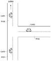
- FIG. 7 shows an example of a map image assigned with a road ID.
- FIG. 7 shows a T-junction, which is a part of a map image displayed on the display of the car navigation system.
- the road ID R100 is shown below the road extending upward in the figure with the intersection as a dividing point.
- Road ID R101 is assigned to the road that extends, and road ID R102 is assigned to the road that extends to the right.
- road ID is memorize
- the vehicle CAR1 travels on the road corresponding to the road ID R100
- the vehicle CAR2 travels on the road corresponding to R101
- the vehicle CAR3 travels on the road corresponding to R102.
- one road ID is assigned for each section delimited by an intersection or for each section delimited by a predetermined distance.
- the size of the intersection serving as a division point may be a large-scale intersection where main roads such as national roads and prefectural roads intersect, or a smaller-scale intersection.
- the division point of the section to which the road ID is assigned is a point where a predetermined number or more vehicles are likely to stop from that point, that is, a point where traffic congestion is likely to occur. It may be set. For example, it may be set at the entrance of a parking lot of a store or business having a capacity greater than or equal to a predetermined value.
- road ID does not need to be given with respect to all the roads in map data.
- the road ID may be given only to roads having a predetermined width or more, or roads having a predetermined number of passing units per unit time or more.
- the section to which the road ID is assigned may be determined manually, or may be automatically set on given map data by setting specific conditions.
- the length of the section to which the road ID is given is preferably determined based on experience, experiments, traffic engineering, or the like so that detailed traffic jam information is communicated to the driver and the section is not unnecessarily subdivided.
- the road ID symbol may be, for example, a serial number, or a combination of a map number within a specific range and a serial number within that range.
- the road ID is not limited to these as long as it is a symbol string according to some form.
- the road ID may or may not be displayed on the map.
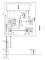
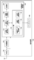
- FIG. 8 shows a configuration of the terminal device 150 according to the present embodiment. Also in this configuration, each functional block can be realized in various forms by hardware alone or a combination of hardware and software.
- the RF unit 102 and the modem unit 104 have the same functions as those described for the terminal device 14 described above.
- the traffic jam display processing unit 160 receives vehicle data including at least a road ID preliminarily assigned to a road section on which the vehicle is traveling and the traveling speed of the vehicle from another vehicle, determines whether there is a traffic jam, and displays on the screen of the display 140. To display.
- the traffic jam display processing unit 160 includes a vehicle speed calculation unit 114, a traffic jam determination unit 120, an information compression unit 122, a transmission unit 124, and a navigation unit 130.
- the vehicle speed calculation unit 114 obtains the traveling speed of a vehicle (not shown) on which the terminal device 150 is mounted.
- the travel speed may be obtained using information from a well-known vehicle speed sensor attached to the vehicle, or the vehicle speed is calculated from the travel distance within a predetermined period of the vehicle position coordinates acquired from the GPS. Also good.
- the traffic jam judgment unit 120 Based on the vehicle data of the other vehicle (hereinafter referred to as “other vehicle data”) and the vehicle data of the own vehicle (hereinafter referred to as “own vehicle data”) received in the inter-vehicle communication, the traffic jam judgment unit 120 And the presence or absence of traffic on the surrounding roads.
- the traffic jam judgment unit 120 basically refers to the traveling speed associated with each road ID included in the other vehicle data and the own vehicle data, and when the traveling speed is equal to or lower than the predetermined speed, the section corresponding to the road ID. Is determined to be congested.
- the predetermined speed may be changed according to the type of road (for example, 20 km / h for general roads, 40 km / h for highways, etc.).
- the traffic jam judgment unit 120 can perform travel speed statistical processing to obtain one travel speed for each road ID and perform traffic jam judgment.
- the statistical processing may be, for example, for obtaining an average value or a median value of traveling speed. Even if the vehicle travels in the same section, the traveling speed varies, such as a fast vehicle, a slow vehicle, or a vehicle that stops at a red light. It can be performed.
- the transmission unit 124 creates a transmission frame including the own vehicle data and all or part of the received other vehicle data.
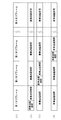
- the host vehicle data includes the road ID of the section in which the host vehicle travels and the traveling speed of the host vehicle (see FIG. 9).
- the road ID of the section in which the host vehicle travels can be obtained by superimposing the position of the host vehicle acquired by the position acquisition unit 136 on map data stored in the map data storage unit 134 described later.
- the information compression unit 122 compresses the data amount of the transmission frame by deleting information unnecessary for traffic jam determination. Thereby, communication traffic between vehicles is reduced.
- the information compression unit 122 receives the traffic jam judgment result for each road ID from the traffic jam judgment unit 120. Then, the travel speed related to the road ID determined not to be congested is deleted from the transmission frame. That is, only the road ID is transmitted in the own vehicle data or other vehicle data of the vehicle traveling in the section corresponding to the road ID determined not to be congested. As described above, the road ID is transmitted even when it is determined that there is no traffic jam for the following reason. That is, if no information is transmitted for a section determined not to be congested, the terminal device of each vehicle does not receive information because there is no vehicle traveling in the section, or no congested traffic has occurred. Therefore, it is impossible to distinguish whether information is not sent. By transmitting the road ID, it can be clearly communicated that there is no traffic jam in the corresponding section. At the same time, by transmitting only road IDs for some sections, the amount of information transmitted and received can be reduced, and communication traffic can be reduced.
- the transmission unit 124 broadcast-transmits a packet including the transmission frame compressed by the information compression unit 122 to terminal devices of an unspecified number of vehicles using a well-known wireless LAN (Local Area Network).
- a wireless LAN Local Area Network
- the terminal device of each vehicle determines whether there is a traffic jam for each road ID based on the other vehicle data and the own vehicle data received from the other vehicle, removes unnecessary information, Broadcast transmission of other vehicle data. Since the vehicle data is transmitted by a multi-hop method, the vehicle data can be transmitted to a vehicle that exists at a position beyond the transmission range of one terminal device. At this time, if the upper limit number of hops is set, the amount of vehicle data for inter-vehicle communication will not continue to increase.
- the traffic jam judgment unit 120 assigns a predetermined travel speed and performs the statistical processing described above. May be implemented.
- the vehicle data that does not include travel speed information is that of a vehicle that is determined not to be congested. Therefore, as the travel speed to be assigned, the above-mentioned predetermined speed when determining the congested traffic (for example, 20 km / h for general roads). On highways, 40 km / h) or higher values are selected.
- the transmission unit 124 integrates other vehicle data having the same road ID received from a plurality of other vehicles into one.
- the other vehicle data has only the road ID
- only one road ID may be included in the transmission frame.
- the other vehicle data includes a road ID and a traveling speed
- one road ID and a value for example, an average value or a median value
- the data amount of the transmission frame can be further reduced. Therefore, communication traffic between vehicles is reduced.
- Navigation unit 130 displays a navigation screen on display 140.
- the navigation unit 130 includes a map data storage unit 134, a position acquisition unit 136, and a display control unit 138.
- the map data storage unit 134 stores map data used for navigation display and traffic jam information display.
- the map data may be pushed and updated by an external server connected via a wireless LAN.
- the map data storage unit 134 also stores road ID data allocated in advance.
- the position acquisition unit 136 is a GPS (Global Positioning System), for example, and acquires the current position of the host vehicle. Since GPS is a well-known technique, detailed description is omitted. Note that the current position may be acquired using another existing technique such as specifying the position based on wireless communication instead of the GPS. By matching the acquired current position of the host vehicle and the map data, the information compression unit 122 and the transmission unit 124 can know the road ID of the section in which the host vehicle travels.
- GPS Global Positioning System
- the display control unit 138 displays a map image of a predetermined range around the host vehicle on the display 140 based on the map data. Further, the display control unit 138 displays traffic jam information based on the traffic jam judgment result for each road ID by the traffic jam judgment unit 120 and the road ID data stored in the map data storage unit 134. For example, the display control unit 138 may give a sign indicating that there is a traffic jam to the road corresponding to the road ID determined as a traffic jam by the traffic jam judgment unit 120 for the road in the direction in which the host vehicle travels. This sign may be a symbol such as “X” for a congested road and “ ⁇ ” for other roads, or a red line or arrow extending over the entire section corresponding to the road ID.
- terminal device 150 may be configured integrally with the terminal device 14 described with reference to FIG. 6 by sharing the RF unit, the modulation / demodulation unit, or the like, or may be configured separately. May be.
- FIG. 9 shows a basic configuration of a frame transmitted and received by inter-vehicle communication.
- this frame includes other vehicle data received from other vehicles existing around the own vehicle in addition to the own vehicle data. Since the packet including this frame is transmitted between vehicles by the multi-hop method, the vehicle data of the own vehicle can be delivered to a vehicle outside the transmission range (for example, a vehicle traveling far behind the own vehicle).
- the own vehicle data and the other vehicle data include the road ID and the traveling speed of the section in which each vehicle is traveling.
- the frame may include a traveling direction of the vehicle, a flag indicating the presence or absence of traveling speed, and the like.
- the inter-vehicle communication may be executed within the vehicle transmission period described with reference to FIG. 3 at the place where the base station device 10 is installed.
- an access control function called CSMA / CA (Carrier Sense Multiple Access with Collision Avoidance) in a wireless LAN (Local Area Network) conforming to a standard such as IEEE 802.11 is used. May be executed.
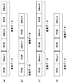
- 10 (a) to 10 (d) show examples in which the data of the transmission frame is compressed by the information compression unit 122.
- the frame data may be compressed on the transmitting vehicle side or on the receiving vehicle side.
- FIG. 10A shows an example of an uncompressed frame.
- the travel speed is not deleted by the information compression unit 122.
- FIG. 10B shows an example in which compression is performed on the transmission vehicle side.
- vehicle CAR3 is traveling at 60 km / h on the section indicated by road ID R102.
- the congestion determination unit 120 of the terminal device mounted on the vehicle CAR3 determines that the section corresponding to the road ID R102 is not congested. Therefore, the information compression unit 122 deletes the traveling speed information of the host vehicle data and includes only the road ID in the frame.
- FIG. 10 (c) and 10 (d) show examples in which compression is performed on the receiving vehicle side.
- FIG. 10 (c) shows a frame received by vehicle CAR2 traveling on the section indicated by road ID R101 from vehicle CAR3 traveling on the section indicated by road ID R102.
- 10 (d) indicates a frame transmitted by the vehicle CAR2.
- the congestion determination unit 120 of the terminal device mounted on the vehicle CAR2 determines that the section corresponding to the road ID R102 is not congested. Therefore, the information compression unit 122 deletes the traveling speed information of the other vehicle data related to R102 and includes only the road ID in the frame.
- FIG. 11 is a flowchart of the inter-vehicle communication process according to the present embodiment.
- the terminal device 150 of each vehicle receives the other vehicle data transmitted from the other vehicle (S10). Based on the received other vehicle data and own vehicle data, the traffic jam judgment unit 120 judges whether there is traffic jam by road ID (S12). This process will be described later with reference to FIG.
- the information compressing unit 122 deletes the associated traveling speed information for the road ID determined by the traffic jam determining unit 120 as not being jammed from the frame including the other vehicle data and the host vehicle data. Then, broadcast transmission is performed by the transmission unit 124 (S14). If it is determined by this process that there is no traffic jam, only the road ID is transmitted as the vehicle data, so that communication traffic is reduced.
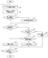
- FIG. 12 is a flowchart of the traffic jam determination process in the traffic jam determination unit 120.
- the traffic jam determination unit 120 selects one of the road IDs included in the received other vehicle data and the own vehicle data (S20).
- the traffic congestion determining unit 120 adds a predetermined traveling speed (S22). This step may not be performed when there is one other vehicle data having the road ID selected in S20.
- the traffic jam judgment unit 120 receives other vehicle data from a plurality of vehicles traveling on the road corresponding to the selected road ID, that is, whether there are a plurality of other vehicle data having the road ID selected in S20. It is determined whether or not (S24). When other vehicle data is received from a plurality of vehicles (Y in S24), statistical processing of the traveling speed of all the vehicles is performed (S26). For example, an average speed is calculated or a median speed is selected.
- the traffic jam judgment unit 120 determines whether or not the traveling speed of the vehicle is equal to or less than a predetermined value (S28). When the statistical process of S26 is performed, the traffic jam determination unit 120 determines whether or not the travel speed after the statistical process is equal to or less than a predetermined value. If the traveling speed is greater than the predetermined value (N in S28), the traffic jam determination unit 120 determines that the section corresponding to the road ID is flowing smoothly (S36).
- the traffic jam determination unit 120 determines whether or not the received other vehicle data is only for one vehicle (S30). In the case of only one vehicle (Y in S30), the determination of traffic congestion in the corresponding section is handled as reference information (S34). In the case of the reference information, for example, the display control unit 138 may change the display mode from normal, for example, the red arrow indicating the traffic jam on the map of the display 140 may be a dotted line, or the traffic jam may be displayed on the map. You may not make it display to the driver without displaying.
- Step S30 is, for example, a situation where one vehicle is stopped due to a break or a failure in the section corresponding to the road ID, or a situation where the vehicle is traveling at a low speed for some reason. Is to eliminate.
- the traffic jam judgment unit 120 determines whether or not similar data is received from a predetermined number of vehicles (S32). In other words, it is determined whether or not the traveling speed before the statistical processing in S26 falls within a predetermined fluctuation range.
- This fluctuation range is based on the threshold for judging traffic congestion, such as 5 km / h for general roads judged to be jammed at 20 km / h or less, and 10 km / h for expressways judged to be jammed at 40 km / h or less.
- the predetermined number is set to the lower limit value of the vehicle that should be determined as a traffic jam. This step is performed in order not to judge a situation where, for example, several vehicles are traveling at a low speed as a traffic jam.
- the traffic jam judgment unit 120 judges that the section corresponding to the road ID is flowing smoothly (S36).
- the traffic jam determination unit 120 determines that the section corresponding to the road ID is traffic jam (S38).
- the traffic jam judgment unit 120 judges whether or not traffic jam judgment has been performed for all the road IDs (S40). If there is a road ID for which no traffic jam has been determined (N in S40), the process returns to S20. When the determination is completed for all road IDs (Y in S40), this flow ends.
- the present embodiment it is possible to determine the presence or absence of traffic congestion only by inter-vehicle communication even in a place where no roadside device is installed. Therefore, it is possible to reduce the installation cost of the roadside machine and to make the judgment of traffic jam in real time.
- the vehicle data is transferred between vehicles by the multi-hop method, it is possible to receive information on other vehicles existing far from the host vehicle. This makes it possible to determine traffic jams over a wide range.
- the transmission data amount between vehicles is compressed by removing the traveling speed information of the vehicle that travels in the section determined not to be congested, thereby reducing communication traffic and using the frequency. Efficiency is improved. Further, since the road ID is also transmitted for a section determined not to be congested, a case where there is no vehicle traveling in the section is distinguished from a case where a vehicle exists but is not congested. be able to.
- a terminal device mounted on a vehicle to perform inter-vehicle communication A map data storage unit that holds map data in which road IDs as identification information are assigned to at least some roads set in advance;
- a traffic jam judgment unit that receives vehicle data including the road ID and the running speed of the vehicle from a vehicle running in the zone, and judges whether or not the zone corresponding to each road ID is jammed;
- a transmission unit that configures and transmits a frame that combines the received vehicle data of the other vehicle and the vehicle data of the host vehicle;
- a terminal device comprising: According to this aspect, by using the road ID assigned to the section set on the map data, it is possible to determine the presence or absence of traffic on the corresponding road for each road ID.
- the traffic jam is determined based on the traveling speed of the vehicle.
- the traffic jam may be determined based on the density of the vehicle.
- the traffic jam judgment unit calculates the vehicle density in the section corresponding to the road ID, that is, the number of vehicles per unit distance.
- the vehicle density can be calculated by (number of other vehicle data having the same road ID) / (actual distance of a section corresponding to the road ID).
- the traffic jam judging unit judges that the section corresponding to the road ID is jammed when the vehicle density is equal to or higher than a predetermined threshold value.
- the threshold value of the vehicle density may be a fixed value determined in consideration of the average distance of the section to which the road ID is allocated, or may be a fluctuation value according to the actual distance of the section corresponding to the road ID. May be.
- the terminal device when the terminal device according to the above-described embodiment is not sufficiently widespread, only the data of some vehicles are communicated between vehicles, and thus the vehicle density cannot be calculated accurately. Therefore, even if the terminal device is configured to be able to add traffic judgment based on speed to the default setting, and traffic congestion judgment based on vehicle density can be added by changing the settings or upgrading the software when the terminal device is widely used. Good.
- communication traffic between vehicles can be reduced in a terminal device that determines the presence or absence of traffic congestion based on vehicle-to-vehicle communication.
- 102 RF section 104 modulation / demodulation section, 114 vehicle speed calculation section, 120 traffic jam judgment section, 122 information compression section, 124 transmission section, 130 navigation section, 134 map data storage section, 136 position acquisition section, 138 display control section, 140 display, 150 terminal device.
Landscapes
- Engineering & Computer Science (AREA)
- Remote Sensing (AREA)
- Radar, Positioning & Navigation (AREA)
- Physics & Mathematics (AREA)
- General Physics & Mathematics (AREA)
- Life Sciences & Earth Sciences (AREA)
- Atmospheric Sciences (AREA)
- Biodiversity & Conservation Biology (AREA)
- Ecology (AREA)
- Environmental & Geological Engineering (AREA)
- Environmental Sciences (AREA)
- Chemical & Material Sciences (AREA)
- Analytical Chemistry (AREA)
- Automation & Control Theory (AREA)
- Traffic Control Systems (AREA)
- Mobile Radio Communication Systems (AREA)
Abstract
Description
送信部124が上記の送信フレームを作成するとき、情報圧縮部122は、渋滞判断に不要である情報を削除して送信フレームのデータ量を圧縮する。これによって、車車間での通信トラフィックが軽減される。
なお、上記フレームには、車両の進行方向や、走行速度の有無を示すフラグなどを含めてもよい。
各車両の端末装置150は、他車両から送信される他車両データを受信する(S10)。渋滞判断部120は、受信した他車両データおよび自車両データに基づき、道路ID別に渋滞の有無を判断する(S12)。この処理は、図12を参照して後述する。情報圧縮部122は、他車両データと自車両データを含んだフレームから、渋滞判断部120により渋滞でないと判断された道路IDについては、関連する走行速度情報を削除する。そして、送信部124によりブロードキャスト送信される(S14)。この処理により、渋滞でないと判断された場合、車両データとして道路IDのみが送信されるので、通信トラフィックが軽減される。
まず、渋滞判断部120は、受信した複数の他車両データおよび自車両データに含まれる道路IDのうち、いずれか一つを選択する(S20)。選択した道路IDが走行速度情報を伴っていない場合、すなわち対応する区間が渋滞していない場合、渋滞判断部120は予め定められた走行速度を付加する(S22)。なお、このステップは、S20で選択された道路IDを有する他車両データが一つの場合には行わなくてよい。
車車間通信を行うために車両に搭載される端末装置であって、
少なくとも一部の道路について予め設定された区間ごとに識別情報としての道路IDが割り振られている地図データを保持する地図データ記憶部と、
前記区間を走行する車両から前記道路IDおよび前記車両の走行速度を含む車両データを受け取り、道路IDごとに対応する区間が渋滞しているか否かを判断する渋滞判断部と、
受信した他車両の車両データと、自車両の車両データとを合わせたフレームを構成して送信する送信部と、
を備えることを特徴とする端末装置。
この態様によると、地図データ上に設定された区間に割り振られている道路IDを使用することで、道路IDごとに対応する道路における渋滞の有無を判断することが可能になる。
Claims (8)
- 車車間通信を行うために車両に搭載される端末装置であって、
少なくとも一部の道路について予め設定された区間ごとに識別情報としての道路IDが割り振られている地図データを参照して、走行中の前記道路IDおよび走行速度を含む自車両の車両データを送信することを特徴とする端末装置。 - 前記道路IDごとに対応する区間が渋滞しているか否かを判断する渋滞判断部と、
他車両の端末装置から受信した車両データと、自車両の車両データとを合わせたフレームを構成して送信する送信部と、
前記渋滞判断部により渋滞していないと判断された区間について前記フレームから走行速度を除く情報圧縮部と、
を備えることを特徴とする請求項1に記載の端末装置。 - 前記情報圧縮部は、前記渋滞判断部により自車両が走行する区間が渋滞していないと判断された場合、前記フレームを構成する自車両の車両データから走行速度を除くことを特徴とする請求項2に記載の端末装置。
- 前記情報圧縮部は、前記渋滞判断部により他車両が走行する区間が渋滞していないと判断された場合、前記フレームを構成する他車両の車両データから走行速度を除くことを特徴とする請求項2に記載の端末装置。
- 前記送信部は、複数の他車両から受信した同一の道路IDを有する車両データを一つに統合することを特徴とする請求項2ないし4のいずれかに記載の端末装置。
- 前記少なくとも一部の道路は、所定の幅員以上の道路または単位時間当たりの通過台数が所定値以上の道路であることを特徴とする請求項1に記載の端末装置。
- 前記渋滞判断部は、同一の道路IDを含む複数の車両データを他車両から受信した場合、該複数の車両データに含まれる走行速度の統計処理を行って、道路IDごとに一つの走行速度を求めて渋滞の有無を判断することを特徴とする請求項2ないし5のいずれかに記載の端末装置。
- 渋滞判断部は、受信した他車両の車両データに走行速度が含まれていないとき、該車両データに含まれる道路IDに予め定められた走行速度を割り当てて前記統計処理を行うことを特徴とする請求項7に記載の端末装置。
Priority Applications (3)
| Application Number | Priority Date | Filing Date | Title |
|---|---|---|---|
| CN201180003374.3A CN102473352B (zh) | 2010-05-31 | 2011-05-30 | 终端装置 |
| JP2012518243A JP5849204B2 (ja) | 2010-05-31 | 2011-05-30 | 端末装置 |
| US13/489,873 US8884781B2 (en) | 2010-05-31 | 2012-06-06 | Terminal apparatus mounted on a vehicle to perform vehicle-to-vehicle communication |
Applications Claiming Priority (4)
| Application Number | Priority Date | Filing Date | Title |
|---|---|---|---|
| JP2010-125036 | 2010-05-31 | ||
| JP2010125035 | 2010-05-31 | ||
| JP2010-125035 | 2010-05-31 | ||
| JP2010125036 | 2010-05-31 |
Related Child Applications (1)
| Application Number | Title | Priority Date | Filing Date |
|---|---|---|---|
| US13/489,873 Continuation US8884781B2 (en) | 2010-05-31 | 2012-06-06 | Terminal apparatus mounted on a vehicle to perform vehicle-to-vehicle communication |
Publications (1)
| Publication Number | Publication Date |
|---|---|
| WO2011152023A1 true WO2011152023A1 (ja) | 2011-12-08 |
Family
ID=45066416
Family Applications (1)
| Application Number | Title | Priority Date | Filing Date |
|---|---|---|---|
| PCT/JP2011/003014 Ceased WO2011152023A1 (ja) | 2010-05-31 | 2011-05-30 | 端末装置 |
Country Status (4)
| Country | Link |
|---|---|
| US (1) | US8884781B2 (ja) |
| JP (1) | JP5849204B2 (ja) |
| CN (1) | CN102473352B (ja) |
| WO (1) | WO2011152023A1 (ja) |
Cited By (6)
| Publication number | Priority date | Publication date | Assignee | Title |
|---|---|---|---|---|
| CN102840862A (zh) * | 2012-08-10 | 2012-12-26 | 乔东江 | 车辆位置信息的发射和获取方法、装置及协同导航设备 |
| JP2014153930A (ja) * | 2013-02-08 | 2014-08-25 | Sumitomo Electric Ind Ltd | 情報通信装置 |
| JP2019211814A (ja) * | 2018-05-31 | 2019-12-12 | 株式会社東芝 | 渋滞予測装置、および、渋滞予測方法 |
| JP6670984B1 (ja) * | 2018-06-27 | 2020-03-25 | 京セラ株式会社 | 無線通信システム、基地局、移動局、及び無線通信方法 |
| CN110954120A (zh) * | 2019-11-12 | 2020-04-03 | 上海博泰悦臻电子设备制造有限公司 | 实时路况导航方法以及系统 |
| US10834658B2 (en) | 2015-07-09 | 2020-11-10 | Denso Corporation | Wireless communication device for vehicle |
Families Citing this family (23)
| Publication number | Priority date | Publication date | Assignee | Title |
|---|---|---|---|---|
| CN102474702A (zh) * | 2010-06-14 | 2012-05-23 | 三洋电机株式会社 | 终端装置 |
| US9253753B2 (en) | 2012-04-24 | 2016-02-02 | Zetta Research And Development Llc-Forc Series | Vehicle-to-vehicle safety transceiver using time slots |
| US9129532B2 (en) | 2012-04-24 | 2015-09-08 | Zetta Research and Development LLC, ForC series | Hybrid protocol transceiver for V2V communication |
| US20130278441A1 (en) | 2012-04-24 | 2013-10-24 | Zetta Research and Development, LLC - ForC Series | Vehicle proxying |
| US9300423B2 (en) | 2012-04-24 | 2016-03-29 | Zetta Research and Development LLC—ForC Series | Device for synchronizing a time base for V2V communictation |
| KR101957943B1 (ko) * | 2012-08-31 | 2019-07-04 | 삼성전자주식회사 | 정보 제공 방법 및 이를 위한 정보 제공 차량 |
| EP3118837B1 (en) | 2012-09-28 | 2017-11-08 | Panasonic Intellectual Property Management Co., Ltd. | Notification device |
| US9117098B2 (en) * | 2013-06-03 | 2015-08-25 | Ford Global Technologies, Llc | On-board traffic density estimator |
| US9123250B2 (en) * | 2013-12-05 | 2015-09-01 | Elwha Llc | Systems and methods for reporting real-time handling characteristics |
| CN105280005A (zh) * | 2014-06-06 | 2016-01-27 | 电信科学技术研究院 | 一种道路安全消息的发送方法及装置 |
| DE102014221726A1 (de) * | 2014-10-24 | 2016-04-28 | Continental Teves Ag & Co. Ohg | Verfahren zum Handhaben einer empfangenen Fahrzeug-zu-X-Nachricht in einem Fahrzeug, Fahrzeug-zu-X-Kommunikationsmodul und Speichermedium |
| JP6513717B2 (ja) * | 2014-10-29 | 2019-05-15 | バイエリシエ・モトーレンウエルケ・アクチエンゲゼルシヤフト | セルラー網での車両通信をサポートするための方法、テレマティックサーバー及び基地局 |
| CN106294474B (zh) * | 2015-06-03 | 2019-07-16 | 阿里巴巴集团控股有限公司 | 显示数据的处理方法、装置及系统 |
| JP6260912B2 (ja) * | 2016-02-09 | 2018-01-17 | 本田技研工業株式会社 | 渋滞箇所情報提供のための装置、方法、及びプログラム |
| KR102263395B1 (ko) * | 2017-07-25 | 2021-06-11 | 삼성전자주식회사 | 외부 이동 수단의 움직임과 관련된 데이터에 기반하여, 식별 정보가 변경된 외부 이동 수단을 확인하는 전자 장치 및 그 동작 방법 |
| KR102432429B1 (ko) * | 2017-12-02 | 2022-08-17 | 현대자동차주식회사 | 차량 및 차량의 제어방법 |
| US10349246B1 (en) * | 2018-05-08 | 2019-07-09 | BaiJie Teng Technology Corporation | Method and system for vehicle-to-vehicle identification and detection |
| US10440709B1 (en) * | 2018-06-04 | 2019-10-08 | Nokia Technologies Oy | Resource allocation scheme for vehicle-to-vehicle (V2V) communications |
| US11348457B2 (en) * | 2018-11-14 | 2022-05-31 | Honda Motor Co., Ltd. | Analysis device and analysis method |
| US11455890B2 (en) * | 2020-03-23 | 2022-09-27 | Toyota Motor Eng & Mfg North America, Inc. | Traffic-adaptive deployment of vehicle functions |
| CN114170807B (zh) * | 2020-09-11 | 2023-04-28 | 北京聚利科技有限公司 | 车辆轨迹信息获取方法、装置、设备和存储介质 |
| US11804132B2 (en) * | 2021-06-10 | 2023-10-31 | Toyota Motor Engineering & Manufacturing North America, Inc. | Systems and methods for displaying bird's eye view of a roadway |
| US11856453B2 (en) | 2021-09-27 | 2023-12-26 | Toyota Motor Engineering & Manufacturing North America, Inc. | Systems and methods for context-based representation of sensor sharing messages |
Citations (6)
| Publication number | Priority date | Publication date | Assignee | Title |
|---|---|---|---|---|
| JP2006072472A (ja) * | 2004-08-31 | 2006-03-16 | Denso Corp | 走行先道路関連情報取得方法および走行先道路関連情報取得装置 |
| JP2007280220A (ja) * | 2006-04-10 | 2007-10-25 | Denso Corp | 車両位置報知装置 |
| JP2008070261A (ja) * | 2006-09-14 | 2008-03-27 | Toshiba Corp | 位置把握システムとその装置及び位置把握方法 |
| JP2009188527A (ja) * | 2008-02-04 | 2009-08-20 | Denso Corp | 車車間通信装置 |
| JP2009199222A (ja) * | 2008-02-20 | 2009-09-03 | Hitachi Kokusai Electric Inc | ナビゲーション装置、受信装置、及び移動体情報提供装置 |
| JP2009217376A (ja) * | 2008-03-07 | 2009-09-24 | Nissan Motor Co Ltd | 交通情報生成システム、交通情報生成装置、及び交通情報生成方法 |
Family Cites Families (7)
| Publication number | Priority date | Publication date | Assignee | Title |
|---|---|---|---|---|
| US7610146B2 (en) * | 1997-10-22 | 2009-10-27 | Intelligent Technologies International, Inc. | Vehicle position determining system and method |
| JP2001124572A (ja) * | 1999-10-29 | 2001-05-11 | Nippon Seiki Co Ltd | 車両用ナビゲーション装置 |
| US6594576B2 (en) * | 2001-07-03 | 2003-07-15 | At Road, Inc. | Using location data to determine traffic information |
| JP4730165B2 (ja) * | 2006-03-27 | 2011-07-20 | 株式会社デンソー | 交通情報管理システム |
| WO2008099716A1 (ja) | 2007-02-14 | 2008-08-21 | Mitsubishi Electric Corporation | 車両用通信装置 |
| US20090140887A1 (en) * | 2007-11-29 | 2009-06-04 | Breed David S | Mapping Techniques Using Probe Vehicles |
| JP5493780B2 (ja) * | 2009-11-30 | 2014-05-14 | 富士通株式会社 | 運転支援装置、運転支援方法及びそのプログラム |
-
2011
- 2011-05-30 WO PCT/JP2011/003014 patent/WO2011152023A1/ja not_active Ceased
- 2011-05-30 CN CN201180003374.3A patent/CN102473352B/zh not_active Expired - Fee Related
- 2011-05-30 JP JP2012518243A patent/JP5849204B2/ja not_active Expired - Fee Related
-
2012
- 2012-06-06 US US13/489,873 patent/US8884781B2/en not_active Expired - Fee Related
Patent Citations (6)
| Publication number | Priority date | Publication date | Assignee | Title |
|---|---|---|---|---|
| JP2006072472A (ja) * | 2004-08-31 | 2006-03-16 | Denso Corp | 走行先道路関連情報取得方法および走行先道路関連情報取得装置 |
| JP2007280220A (ja) * | 2006-04-10 | 2007-10-25 | Denso Corp | 車両位置報知装置 |
| JP2008070261A (ja) * | 2006-09-14 | 2008-03-27 | Toshiba Corp | 位置把握システムとその装置及び位置把握方法 |
| JP2009188527A (ja) * | 2008-02-04 | 2009-08-20 | Denso Corp | 車車間通信装置 |
| JP2009199222A (ja) * | 2008-02-20 | 2009-09-03 | Hitachi Kokusai Electric Inc | ナビゲーション装置、受信装置、及び移動体情報提供装置 |
| JP2009217376A (ja) * | 2008-03-07 | 2009-09-24 | Nissan Motor Co Ltd | 交通情報生成システム、交通情報生成装置、及び交通情報生成方法 |
Cited By (7)
| Publication number | Priority date | Publication date | Assignee | Title |
|---|---|---|---|---|
| CN102840862A (zh) * | 2012-08-10 | 2012-12-26 | 乔东江 | 车辆位置信息的发射和获取方法、装置及协同导航设备 |
| JP2014153930A (ja) * | 2013-02-08 | 2014-08-25 | Sumitomo Electric Ind Ltd | 情報通信装置 |
| US10834658B2 (en) | 2015-07-09 | 2020-11-10 | Denso Corporation | Wireless communication device for vehicle |
| JP2019211814A (ja) * | 2018-05-31 | 2019-12-12 | 株式会社東芝 | 渋滞予測装置、および、渋滞予測方法 |
| JP7086725B2 (ja) | 2018-05-31 | 2022-06-20 | 株式会社東芝 | 渋滞予測装置、および、渋滞予測方法 |
| JP6670984B1 (ja) * | 2018-06-27 | 2020-03-25 | 京セラ株式会社 | 無線通信システム、基地局、移動局、及び無線通信方法 |
| CN110954120A (zh) * | 2019-11-12 | 2020-04-03 | 上海博泰悦臻电子设备制造有限公司 | 实时路况导航方法以及系统 |
Also Published As
| Publication number | Publication date |
|---|---|
| JPWO2011152023A1 (ja) | 2013-07-25 |
| US8884781B2 (en) | 2014-11-11 |
| CN102473352A (zh) | 2012-05-23 |
| US20120268295A1 (en) | 2012-10-25 |
| JP5849204B2 (ja) | 2016-01-27 |
| CN102473352B (zh) | 2014-07-02 |
Similar Documents
| Publication | Publication Date | Title |
|---|---|---|
| JP5849204B2 (ja) | 端末装置 | |
| JP2012015714A (ja) | 端末装置 | |
| JP5442885B2 (ja) | 無線装置 | |
| JP5895199B2 (ja) | 無線装置 | |
| US20130314253A1 (en) | Radio apparatus that receives signals containing predetermined information | |
| WO2014049987A1 (ja) | 通知装置およびそれを利用した車両 | |
| JP5754998B2 (ja) | 端末装置 | |
| JPWO2011145344A1 (ja) | 基地局装置 | |
| JP5579511B2 (ja) | 端末装置 | |
| US20120269121A1 (en) | Base station apparatus for transmitting or receiving a signal including predetermined information | |
| JP2011205350A (ja) | 端末装置 | |
| WO2011152022A1 (ja) | 端末装置 | |
| JP2012003352A (ja) | 端末装置 | |
| JP2011035566A (ja) | 端末装置 | |
| JPWO2011158484A1 (ja) | 端末装置 | |
| JPWO2012131830A1 (ja) | 端末装置 | |
| WO2013046655A1 (ja) | 無線装置 | |
| JP2011182138A (ja) | 基地局装置および端末装置 | |
| JP2012003354A (ja) | 基地局装置 | |
| JP2012199860A (ja) | 端末装置 | |
| JP2011182137A (ja) | 基地局装置 | |
| JP2014199961A (ja) | 無線装置 | |
| WO2013018318A1 (ja) | 通信システムおよび基地局装置、無線装置 | |
| JP2014199962A (ja) | 通信システムおよび基地局装置 | |
| JP2011035659A (ja) | 端末装置 |
Legal Events
| Date | Code | Title | Description |
|---|---|---|---|
| WWE | Wipo information: entry into national phase |
Ref document number: 201180003374.3 Country of ref document: CN |
|
| WWE | Wipo information: entry into national phase |
Ref document number: 2012518243 Country of ref document: JP |
|
| 121 | Ep: the epo has been informed by wipo that ep was designated in this application |
Ref document number: 11789437 Country of ref document: EP Kind code of ref document: A1 |
|
| NENP | Non-entry into the national phase |
Ref country code: DE |
|
| 122 | Ep: pct application non-entry in european phase |
Ref document number: 11789437 Country of ref document: EP Kind code of ref document: A1 |