WO2011148844A1 - ガラス基板およびその製造方法 - Google Patents
ガラス基板およびその製造方法 Download PDFInfo
- Publication number
- WO2011148844A1 WO2011148844A1 PCT/JP2011/061486 JP2011061486W WO2011148844A1 WO 2011148844 A1 WO2011148844 A1 WO 2011148844A1 JP 2011061486 W JP2011061486 W JP 2011061486W WO 2011148844 A1 WO2011148844 A1 WO 2011148844A1
- Authority
- WO
- WIPO (PCT)
- Prior art keywords
- glass substrate
- cleaning
- substrate
- magnetic
- layer
- Prior art date
- Legal status (The legal status is an assumption and is not a legal conclusion. Google has not performed a legal analysis and makes no representation as to the accuracy of the status listed.)
- Ceased
Links
Images





Classifications
-
- G—PHYSICS
- G11—INFORMATION STORAGE
- G11B—INFORMATION STORAGE BASED ON RELATIVE MOVEMENT BETWEEN RECORD CARRIER AND TRANSDUCER
- G11B5/00—Recording by magnetisation or demagnetisation of a record carrier; Reproducing by magnetic means; Record carriers therefor
- G11B5/84—Processes or apparatus specially adapted for manufacturing record carriers
- G11B5/8404—Processes or apparatus specially adapted for manufacturing record carriers manufacturing base layers
Definitions
- the present invention relates to a glass substrate suitable as a substrate for an information recording medium such as a hard disk (HDD), particularly a substrate for a heat-assisted recording medium, and a method for manufacturing the same.
- an information recording medium such as a hard disk (HDD)
- HDD hard disk
- an aluminum alloy has been used as a substrate for an information recording medium such as a hard disk (HDD).
- HDD hard disk
- glass substrates are now widely used.
- Such a glass substrate and a manufacturing method thereof are disclosed in JP 2000-169184 A (Patent Document 1), JP 2006-327935 A (Patent Document 2), JP 2006-327936 A (Patent Document 3), It is disclosed in Japanese Patent Application Laid-Open No. 2007-161552 (Patent Document 4) and International Publication No. 2009/028570 (Patent Document 5).
- heat assist recording As a means for solving such a problem, an information recording means of a method called heat assist recording has been attracting attention.
- This heat-assisted recording is intended to solve the above-described problems by recording information while heating a substrate for a recording medium with a laser.
- a glass substrate is used as a substrate (hereinafter also referred to as “substrate for heat-assisted recording medium”), and a magnetic recording layer (hereinafter referred to as a plurality of layers) is formed on the glass substrate.
- substrate for heat-assisted recording medium a substrate for heat-assisted recording medium
- a magnetic recording layer hereinafter referred to as a plurality of layers
- it has a special feature that an extremely high temperature of about 550 ° C. is applied at the time of formation (film formation) for the purpose of densifying the recording layer. Have.
- a post-heating treatment of about 600 ° C. is performed for the purpose of improving the magnetocrystalline anisotropy of the recording layer.
- the present invention has been made in view of the above situation, and an object of the present invention is to provide a glass substrate and a method for manufacturing the same that can reduce the occurrence rate of read errors. .
- a glass substrate based on this invention it is used as a substrate of a thermally assisted magnetic recording medium, and is a manufacturing method of a glass substrate in which a magnetic recording layer is formed on the surface thereof.
- a substrate cleaning step is included in the process, and the substrate cleaning step includes a step of removing organic substances after cleaning with a detergent.
- the step of removing the organic substance is a step of removing the organic substance using ozone water.
- the step of removing the organic substance is dry cleaning.
- the dry cleaning is ultraviolet ozone cleaning.
- the total amount of organic substances on the surface of the glass substrate subjected to the step of removing the organic substances is 50 ng / cm 2 or less.
- the total amount of organic substances on the surface of the glass substrate subjected to the step of removing the organic substances is 30 ng / cm 2 or less.
- the glass substrate according to the present invention is a glass substrate that is used as a substrate for a thermally assisted magnetic recording medium and is manufactured using a method for manufacturing a glass substrate on which a magnetic recording layer is formed,
- the manufacturing method of a glass substrate includes a substrate cleaning process in the manufacturing process of the glass substrate, and the substrate cleaning process includes a process of removing organic substances after cleaning using a detergent.
- the glass substrate and the manufacturing method thereof according to the present invention there is an excellent effect that the error rate of information can be reduced.
- FIG. 1 is a plan view showing a schematic configuration of a thermally-assisted magnetic recording apparatus in an embodiment.
- 1 is a side view showing a schematic configuration of a heat-assisted magnetic recording apparatus in an embodiment. It is a perspective view which shows the glass substrate used for the magnetic disc in embodiment. 1 is a perspective view showing a magnetic disk in an embodiment. It is a partial expanded sectional view of the other magnetic disc in an embodiment.
- It is a flowchart which shows the manufacturing process of the glass substrate in embodiment. It is a flowchart of Example 1 of the washing
- FIG. 1 is a plan view showing a schematic configuration of the heat-assisted magnetic recording apparatus 2
- FIG. 2 is a side view showing a schematic configuration of the heat-assisted magnetic recording apparatus 2.
- a magnetic recording head 2D is disposed to face a magnetic disk 1 for heat-assisted magnetic recording that is a recording medium that is rotationally driven in the direction of arrow DR1. .
- the magnetic recording head 2D is mounted on the tip of the suspension 2C.
- the suspension 2C is provided so as to be rotatable in the direction of the arrow DR2 (tracking direction) with the support shaft 2A as a fulcrum.
- a tracking actuator 2B is attached to the support shaft 2A.
- the laser beam LB is irradiated on the side facing the magnetic recording head 2D across the magnetic disk 1. A portion to be recorded on the magnetic disk 1 is instantaneously heated by the laser beam LB, and data is recorded on the magnetic disk 1 by the magnetic recording head 2D.
- the magnetic particles of the magnetic layer formed on the magnetic disk 1 have a lower holding force as the temperature rises.
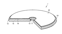
- FIG. 1 is a perspective view showing a glass substrate 1G used for the magnetic disk 1
- FIG. 4 is a perspective view showing the magnetic disk 1. As shown in FIG.
- the glass substrate 1G used for the magnetic disk 1 has an annular disk shape with a hole 11 formed in the center.
- the glass substrate 1G has an outer peripheral end face 12, an inner peripheral end face 13, a front main surface 14, and a back main surface 15.
- the outer diameter is about 64 mm
- the inner diameter is about 20 mm
- the thickness is about 0.8 mm.
- a magnetic layer 23 is formed on the front main surface 14 of the glass substrate 1G.
- the magnetic layer 23 is formed only on the front main surface 14, but it is also possible to provide the magnetic layer 23 on the back main surface 14.
- a conventionally known method can be used. For example, a method in which a thermosetting resin in which magnetic particles are dispersed is spin-coated on a substrate, or a method in which sputtering or electroless plating is used. A method is mentioned.
- the film thickness by spin coating is about 0.3 to 1.2 ⁇ m
- the film thickness by sputtering is about 0.04 to 0.08 ⁇ m
- the film thickness by electroless plating is 0.05 to 0.1 ⁇ m. From the viewpoint of thinning and densification, film formation by sputtering and electroless plating is preferable.
- the magnetic material used for the magnetic layer 23 is not particularly limited, and a conventionally known material can be used. However, in order to obtain a high coercive force, Co having high crystal anisotropy is basically used, and Ni is used for the purpose of adjusting the residual magnetic flux density. A Co-based alloy or the like to which Cr is added is suitable. In recent years, FePt-based materials have been used as magnetic layer materials suitable for heat-assisted recording.
- a lubricant may be thinly coated on the surface of the magnetic layer 23 in order to improve the sliding of the magnetic recording head.
- the lubricant include those obtained by diluting perfluoropolyether (PFPE), which is a liquid lubricant, with a freon-based solvent.
- an underlayer or a protective layer may be provided.
- the underlayer in the magnetic disk is selected according to the magnetic film.
- the material for the underlayer include at least one material selected from nonmagnetic metals such as Cr, Mo, Ta, Ti, W, V, B, Al, and Ni.
- the underlayer is not limited to a single layer, and may have a multi-layer structure in which the same or different layers are stacked.
- a multilayer underlayer such as Cr / Cr, Cr / CrMo, Cr / CrV, NiAl / Cr, NiAl / CrMo, or NiAl / CrV may be used.
- Examples of the protective layer for preventing wear and corrosion of the magnetic layer 23 include a Cr layer, a Cr alloy layer, a carbon layer, a hydrogenated carbon layer, a zirconia layer, and a silica layer. These protective layers can be formed continuously with an in-line type sputtering apparatus, such as an underlayer and a magnetic film. In addition, these protective layers may be a single layer, or may have a multilayer structure including the same or different layers.
- a tetraalkoxylane is diluted with an alcohol solvent on the Cr layer, and then colloidal silica fine particles are dispersed and applied, followed by baking to form a silicon oxide (SiO2) layer. May be.
- FIG. 5 shows an example of the configuration of another magnetic disk 1A.
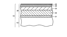
- FIG. 5 is a partially enlarged cross-sectional view of another magnetic disk 1A.
- a recording layer 20 having a plurality of layers is formed on a glass substrate 1G.
- the recording layer 20 has a seed (unevenness control) layer 21 made of AlN or the like directly formed on the main surface 14 of the glass substrate 1G, and a thickness of about 60 nm formed on the seed (unevenness control) layer 21.
- the base layer 22, the magnetic layer 23 having a thickness of about 30 nm formed on the base layer 22, the protective layer 24 having a thickness of about 10 nm formed on the magnetic layer 23, and the protective layer 24 are formed.
- a lubricating layer 25 having a thickness of about 0.8 nm is included.
- the configuration of the magnetic disk 1A is merely an example, and the size of the glass substrate 1G and the configuration of the recording layer 20 are appropriately changed according to the performance required for the magnetic disk 1A.
- step 10 a “glass melting step” in step 10 (hereinafter abbreviated as “S10”, the same applies to step 20 and subsequent steps), the glass material constituting the substrate is melted.
- step 20 the same applies to step 20 and subsequent steps
- the molten glass is poured onto the lower mold and press molded with the upper mold.
- the surface of the press-molded glass substrate is polished and the flatness of the glass substrate is preliminarily adjusted. Further, in the “precision polishing step” of S40, the glass substrate is subjected to polishing processing again, and the flatness and the like are finely adjusted.
- the glass substrate is cleaned. Through the above steps, a glass substrate applicable to the hard disk substrate is obtained.
- a film to be a recording layer is formed on the glass substrate.
- heat treatment for improving the crystal magnetic field anisotropy is performed.
- the heating temperature is about 600 ° C.
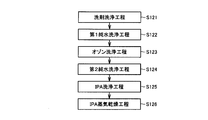
- FIG. 7 shows a cleaning flowchart of cleaning example 1
- FIG. 8 shows a cleaning flowchart of cleaning example 2.
- the cleaning flow of cleaning example 1 shown in FIG. 7 includes a detergent cleaning step (S121), a first pure water cleaning step (S122), an ozone cleaning step (S123), a second pure water cleaning step (S124), and IPA (isopropyl alcohol). )
- the cleaning process (S125) is sequentially performed. In steps S121 to S125, the glass substrate is sequentially immersed in each cleaning tank, and cleaning is performed using ultrasonic waves.
- the cleaning time in each tank is doubled as usual, 6 minutes in the detergent cleaning process (S121), 3 minutes in the first pure water cleaning process (S122), and 6 minutes to 8 minutes in the ozone cleaning process (S123).
- the cleaning time is 3 minutes
- the IPA (isopropyl alcohol) cleaning (S125) the cleaning time is 3 minutes.
- IPA was steam-dried (S126).
- the UV (ultraviolet) ozone cleaning process (S127) is performed after the IPA vapor drying process (S126) of the cleaning example 1.
- UV ozone cleaning step (S127) ultraviolet rays were irradiated for about 10 minutes using a low-pressure mercury lamp.
- FIG. 9 shows the measurement results of the total amount of organic matter (ng / cm 2 ) and the number of surface defects of the magnetic media and the judgment results of the media quality (magnetic disk) in Examples 1 to 6 and Comparative Examples 1 and 2. Show. Further, “cleaning conditions” and “details” in each example and comparative example are shown in FIG. Examples 1 to 3 differ only in the time of the ozone cleaning process in Cleaning Example 1, and Examples 4 to 6 differ only in the time of the ozone cleaning process in Cleaning Example 2.
- the total amount of organic substances (ng / cm 2 ) indicates the amount measured with a GC-MS (gas chromatograph / mass spectrum) tester.
- the GC-MS tester is a composite device of two types of devices, a gas chromatography device and a mass spectrum device.
- the glass substrate is crushed and sealed in a closed system.
- this system is heated to 200 ° C or higher, organic substances are combusted and carbon dioxide is released into the system.
- the gas in the system is passed through a GC-MS tester together with the carrier gas, a carbon dioxide signal is observed.
- the amount of carbon dioxide gas that is, the amount of organic contamination can be measured from the signal area.
- Comparative Example 2 doubled the cleaning time of each cleaning tank of Comparative Example 1. By increasing the cleaning time, Comparative Example 2 has a lower total organic content than Comparative Example 1, but 60 ng / cm 2 is the limit.
- the total amount of organic matter (ng / cm 2 ) after manufacturing the crow substrate is 50 ng / cm 2 or less, sufficient media quality can be obtained even when used as a magnetic disk. It is done. More preferably, it is 30 ng / cm 2 or less.
- the ozone cleaning process (S123) and the UV ozone cleaning process (S127) into the cleaning process after the detergent cleaning process (S121), the total amount of organic substances (ng / cm 2 ) after the production of the crow substrate is reduced. Can be made.
- the ozone water has a high redox potential, that is, has an oxidizing power. For this reason, organic substances present on the substrate surface can be decomposed. After removing rough impurities with the first pure water cleaning, the organic matter can be effectively removed by decomposing the organic matter with ozone cleaning and removing the organic matter decomposed with the second pure water cleaning. .
- the UV ozone cleaning in the UV ozone cleaning step (S127), which is performed after the IPA vapor drying step (S126), is a dry process in which organic substances adhering to the surface are oxidatively decomposed and scattered into the atmosphere. When irradiated with ultraviolet rays, the organic substance bond is broken, and simultaneously with the generated active oxygen, it is converted into a volatile substance (CO 2 or the like) and can be decomposed and removed from the surface. Therefore, only organic substances can be effectively removed by performing UV ozone cleaning in the final process of the cleaning process. Since UV ozone cleaning is a dry process, a subsequent drying step is unnecessary.
- an ozone cleaning process (S123) and a UV ozone cleaning process (S127) are integrated in a cleaning process after a detergent cleaning process (S121), and manufacture of a crow board
- the total amount of organic matter (ng / cm 2 ) later can be reduced.
Landscapes
- Engineering & Computer Science (AREA)
- Manufacturing & Machinery (AREA)
- Manufacturing Of Magnetic Record Carriers (AREA)
- Magnetic Record Carriers (AREA)
Abstract
熱アシスト磁気記録用媒体の基板として用いられ、その表面に磁気記録層が形成されるガラス基板の製造方法であって、ガラス基板の製造工程中に基板洗浄工程を含み、この基板洗浄工程は、洗剤を用いた洗浄後に有機物を除去する工程を有する。
Description
本発明は、ハードディスク(HDD)等の情報記録媒体用の基板、特に熱アシスト記録媒体用の基板として適するガラス基板およびその製造方法に関する。
従来、ハードディスク(HDD)等の情報記録媒体用の基板としては、アルミニウム合金が用いられていた。しかしながら、アルミニウム合金は、変形しやすく、また研磨後の基板表面の平滑性が十分ではない等の問題を有していたため、現在ではガラス基板が広く使用されている。このようなガラス基板およびその製造方法は、特開2000-169184号公報(特許文献1)、特開2006-327935号公報(特許文献2)、特開2006-327936号公報(特許文献3)、特開2007-161552号公報(特許文献4)、および、国際公開第2009/028570号パンフレット(特許文献5)に開示されている。
昨今、上記のような情報記録媒体においては、その情報記録量の増大に伴って記録密度を超高密度状態とすることが求められている。記録手段としては磁性方式が採用されているため、記録密度を高密度化すると記録の保持力が弱くなり、所謂「熱揺らぎ」として知られるように、記録中に発生する熱の影響により記録が消失してしまうという問題があった。
このような問題を解決する手段として、熱アシスト記録という方式の情報記録手段が注目されている。この熱アシスト記録は、レーザで記録媒体用の基板を加熱しながら情報記録を行なうことにより、上記のような問題を解決しようとするものである。このような熱アシスト記録方式の記録媒体は、基板(以下、「熱アシスト記録媒体用の基板」ともいう)としてガラス基板が用いられ、そのガラス基板上に複数の層からなる磁性記録層(以下単に「記録層」という)を形成した構成を有するが、該記録層を緻密化させることを目的としてその形成時(成膜時)に550℃程度の極めて高い温度が適用されるという特殊性を有している。
さらに、記録層を形成した後に、記録層の結晶磁気異方性を向上させる目的から、約600℃程度の後加熱処理が行なわれている。
このように高温の加熱処理を施した場合には、情報記録媒体のガラス基板に付着していた有機物系異物(たとえば、クリーンルームの建築、内装材料から発生する割合が極めて高く、特に塩化ビニル(PVC)の可塑剤であるフタル酸エステル類(DMP、DEP、DBP、DOP)の影響は極めて大きい。その他、天井や壁に使用されるシリコーン系シール材の原料である低分子量環状シロキサン(LMCS)の影響もある。なお、有機系異物はこれらに限らない。)等の体積膨張を発端として、記録層のガラス基板からの膜剥がれや、膜浮きが問題となる。ガラス基板を用いた情報記録媒体に膜剥がれや、膜浮きが発生した場合には、情報記録媒体をハードディスクとして用いた場合には、動作した際にリードエラーを発生させる要因となる。
本発明は、上記のような現状に鑑みなされたものであって、その目的とするところは、リードエラーの発生率を低下させることを可能とするガラス基板およびその製造方法を提供することにある。
この発明に基づいた、ガラス基板の製造方法においては、熱アシスト磁気記録用媒体の基板として用いられ、その表面に磁気記録層が形成されるガラス基板の製造方法であって、上記ガラス基板の製造工程中に基板洗浄工程を含み、上記基板洗浄工程は洗剤を用いた洗浄後に有機物を除去する工程を有する。
この発明に基づいた、ガラス基板の製造方法の他の形態においては、上記有機物を除去する工程は、オゾン水を用いて有機物を除去する工程である。
この発明に基づいた、ガラス基板の製造方法の他の形態においては、上記有機物を除去する工程は、ドライ洗浄である。上記ドライ洗浄は、紫外線オゾン洗浄である。
この発明に基づいた、ガラス基板の製造方法の他の形態においては、上記有機物を除去する工程を施した当該ガラス基板表面の有機物総量は、50ng/cm2以下である。
この発明に基づいた、ガラス基板の製造方法の他の形態においては、上記有機物を除去する工程を施した当該ガラス基板表面の有機物総量は、30ng/cm2以下である。
この発明に基づいたガラス基板においては、熱アシスト磁気記録用媒体の基板として用いられ、その表面に磁気記録層が形成されるガラス基板の製造方法を用いて製造されたガラス基板であって、上記ガラス基板の製造方法は、上記ガラス基板の製造工程中に基板洗浄工程を含み、上記基板洗浄工程は、洗剤を用いた洗浄後に有機物を除去する工程を有する。
この発明に基づいたガラス基板およびその製造方法によれば、情報のエラー発生率を低下させことができるという優れた効果を有する。
本発明に基づいたガラス基板およびその製造方法について、以下、図を参照しながら説明する。なお、以下に説明する実施の形態において、個数、量などに言及する場合、特に記載がある場合を除き、本発明の範囲は必ずしもその個数、量などに限定されない。
また、同一の部品、相当部品に対しては、同一の参照番号を付し、重複する説明は繰り返さない場合がある。また、各実施の形態における構成を適宜組み合わせて用いることは当初から予定されていることである。
(熱アシスト磁気記録装置2の概略構成)
まず、図1および図2を参照して、熱アシスト磁気記録装置2の概略構成の一例について説明する。なお、図1は、熱アシスト磁気記録装置2の概略構成を示す平面図、図2は、熱アシスト磁気記録装置2の概略構成を示す側面図である。
まず、図1および図2を参照して、熱アシスト磁気記録装置2の概略構成の一例について説明する。なお、図1は、熱アシスト磁気記録装置2の概略構成を示す平面図、図2は、熱アシスト磁気記録装置2の概略構成を示す側面図である。
図1に示すように、熱アシスト磁気記録装置2は、矢印DR1方向に回転駆動される記録媒体である熱アシスト磁気記録用の磁気ディスク1に対して、磁気記録ヘッド2Dが対向配置されている。
磁気記録ヘッド2Dは、サスペンション2Cの先端部に搭載されている。サスペンション2Cは、支軸2Aを支点として矢印DR2方向(トラッキング方向)に回動可能に設けられている。支軸2Aには、トラッキング用アクチュエータ2Bが取り付けられている。
図2に示すように、磁気ディスク1を挟んで、磁気記録ヘッド2Dが対向する側には、レーザ光LBが照射される。磁気ディスク1上の記録する部分をレーザ光LBで瞬間的に加熱し、磁気記録ヘッド2Dで磁気ディスク1にデータを記録する。
磁気ディスク1に形成された磁性層の磁気粒子は、その温度が上昇すると保持力が低くなる。レーザ光LBで磁性層を加熱することで、常温では高い保持力を有する磁性層でも、通常の磁気記録ヘッド2Dでの記録が可能となり、超高密度記録の実現を可能とする。
(磁気ディスク1の構成)
次に、図3および図4を参照して、磁気ディスク1の構成について説明する。なお、図3は、磁気ディスク1に用いられるガラス基板1Gを示す斜視図、図4は、磁気ディスク1を示す斜視図である。
次に、図3および図4を参照して、磁気ディスク1の構成について説明する。なお、図3は、磁気ディスク1に用いられるガラス基板1Gを示す斜視図、図4は、磁気ディスク1を示す斜視図である。
図3に示すように、磁気ディスク1に用いられるガラス基板1Gは、中心に孔11が形成された環状の円板形状を呈している。ガラス基板1Gは、外周端面12、内周端面13、表主表面14、および裏主表面15を有している。ガラス基板1Gの大きさの一例としては、外径約64mm、内径約20mm、厚さ約0.8mmである。
図4に示すように、磁気ディスク1は、上記したガラス基板1Gの表主表面14上に磁性層23が形成されている。図示では、表主表面14上にのみ磁性層23が形成されているが、裏主表面14上に磁性層23を設けることも可能である。
磁性層23の形成方法としては従来公知の方法を用いることができ、例えば磁性粒子を分散させた熱硬化性樹脂を基板上にスピンコートして形成する方法や、スパッタリング、無電解めっきにより形成する方法が挙げられる。
スピンコート法での膜厚は約0.3~1.2μm程度、スパッタリング法での膜厚は0.04~0.08μm程度、無電解めっき法での膜厚は0.05~0.1μm程度であり、薄膜化および高密度化の観点からはスパッタリング法および無電解めっき法による膜形成が好ましい。
磁性層23に用いる磁性材料としては、特に限定はなく従来公知のものが使用できるが、高い保持力を得るために結晶異方性の高いCoを基本とし、残留磁束密度を調整する目的でNiやCrを加えたCo系合金などが好適である。近年では、熱アシスト記録用に好適な磁性層材料として、FePt系の材料が用いられるようになってきている。
また、磁気記録ヘッドの滑りをよくするために磁性層23の表面に潤滑剤を薄くコーティングしてもよい。潤滑剤としては、例えば液体潤滑剤であるパーフロロポリエーテル(PFPE)をフレオン系などの溶媒で希釈したものが挙げられる。
さらに必要により下地層や保護層を設けてもよい。磁気ディスクにおける下地層は磁性膜に応じて選択される。下地層の材料としては、例えば、Cr、Mo、Ta、Ti、W、V、B、Al、Niなどの非磁性金属から選ばれる少なくとも一種以上の材料が挙げられる。
また、下地層は単層とは限らず、同一又は異種の層を積層した複数層構造としても構わない。例えば、Cr/Cr、Cr/CrMo、Cr/CrV、NiAl/Cr、NiAl/CrMo、NiAl/CrV等の多層下地層としてもよい。
磁性層23の摩耗や腐食を防止する保護層としては、例えば、Cr層、Cr合金層、カーボン層、水素化カーボン層、ジルコニア層、シリカ層などが挙げられる。これらの保護層は、下地層、磁性膜など共にインライン型スパッタ装置で連続して形成できる。また、これらの保護層は、単層としてもよく、あるいは、同一又は異種の層からなる多層構成としてもよい。
なお、上記保護層上に、あるいは上記保護層に替えて、他の保護層を形成してもよい。例えば、上記保護層に替えて、Cr層の上にテトラアルコキシランをアルコール系の溶媒で希釈した中に、コロイダルシリカ微粒子を分散して塗布し、さらに焼成して酸化ケイ素(SiO2)層を形成してもよい。
(磁気ディスク1A)
図5に、他の磁気ディスク1Aの構成の一例を示す。図5は、他の磁気ディスク1Aの部分拡大断面図である。この磁気ディスク1Aは、ガラス基板1Gの上に複数層を有する記録層20が形成されている。
図5に、他の磁気ディスク1Aの構成の一例を示す。図5は、他の磁気ディスク1Aの部分拡大断面図である。この磁気ディスク1Aは、ガラス基板1Gの上に複数層を有する記録層20が形成されている。
記録層20は、ガラス基板1Gの表主表面14上に直接形成されるAlN等からなるシード(凹凸制御)層21、シード(凹凸制御)層21の上に形成される厚さ約60nmの下地層22、下地層22の上に形成される厚さ約30nmの磁性層23、磁性層23の上に形成される厚さ約10nmの保護層24、および、保護層24の上に形成される厚さ約0.8nmの潤滑層25を含んでいる。
なお、上記磁気ディスク1Aの構成はあくまでも一例であり、磁気ディスク1Aに要求される性能に応じて、ガラス基板1Gの大きさ、記録層20の構成は適宜変更される。
(ガラス基板1Gの製造工程)
次に、図6のフローチャートを用いて、本実施の形態に係るガラス基板を含むハードディスク用基板の製造方法を説明する。
次に、図6のフローチャートを用いて、本実施の形態に係るガラス基板を含むハードディスク用基板の製造方法を説明する。
まず、ステップ10(以下、「S10」と略す。ステップ20以降も同様。)の「ガラス溶融工程」において、基板を構成するガラス素材を溶融する。次に、S20の「プレス成形工程」において、溶融ガラスを下型上に流し込み、上型によってプレス成形する。
S30の「粗研磨工程」において、プレス成形されたガラス基板の表面が研磨加工され、ガラス基板の平坦度などが予備調整される。さらに、S40の「精密研磨工程」において、ガラス基板に研磨加工が再度施され、平坦度などが微調整される。
次に、S50の「洗浄工程」において、ガラス基板は洗浄される。以上の工程により、ハードディスク用基板に適用可能なガラス基板が得られる。
さらに、S60の「成膜工程」において、上記のガラス基板上に、記録層となる膜が形成される。最後に、S70の「後熱処理工程」において、結晶磁界異方性向上のための加熱処理を施す。加熱温度は、約600℃である。以上により、ハードディスク(磁気ディスク)が完成する。
(S50の「洗浄工程」の詳細)
次に、図7を参照して、S50の「洗浄工程」の洗浄例1および洗浄例2について詳細について説明する。洗浄例1の洗浄フロー図を図7に示し、洗浄例2の洗浄フロー図を図8に示す。
次に、図7を参照して、S50の「洗浄工程」の洗浄例1および洗浄例2について詳細について説明する。洗浄例1の洗浄フロー図を図7に示し、洗浄例2の洗浄フロー図を図8に示す。
図7に示す洗浄例1の洗浄フローは、洗剤洗浄工程(S121)、第1純水洗浄工程(S122)、オゾン洗浄工程(S123)、第2純水洗浄工程(S124)、IPA(イソプロピルアルコール)洗浄工程(S125)、を順次行なう。S121~S125の工程は、各洗浄槽にガラス基板を順次浸漬し、超音波を用いて洗浄をおこなう。
洗剤洗浄工程(S121)では、洗剤としてはpH11のアルカリ洗剤を用い、通常の3倍である濃度9%を用いた。
また、各槽での洗浄時間は通常の2倍として、洗剤洗浄工程(S121)では6分、第1純水洗浄工程(S122)では3分、オゾン洗浄工程(S123)では6分~8分、第2純水洗浄工程(S124)では、3分、IPA(イソプロピルアルコール)洗浄(S125)では3分の洗浄時間とした。
その後、IPAの蒸気乾燥を実施した(S126)。
図8に示す洗浄例2の洗浄フローは、洗浄例1のIPA蒸気乾燥工程(S126)の後に、UV(紫外線)オゾン洗浄工程(S127)を実施している。UVオゾン洗浄工程(S127)では、低圧水銀ランプを用いて約10分の紫外線を照射した。
図8に示す洗浄例2の洗浄フローは、洗浄例1のIPA蒸気乾燥工程(S126)の後に、UV(紫外線)オゾン洗浄工程(S127)を実施している。UVオゾン洗浄工程(S127)では、低圧水銀ランプを用いて約10分の紫外線を照射した。
図9に、実施例1~実施例6、および比較例1、2における、有機物総量(ng/cm2)および磁気メディアの表面ディフェクト数の測定結果と、メディア品質(磁気ディスク)の判定結果を示す。また、各実施例および比較例での「洗浄条件」および「詳細」を図9中に示す。実施例1~3は、洗浄例1におけるオゾン洗浄工程の時間のみが異なり、実施例4~6は、洗浄例2におけるオゾン洗浄工程の時間のみが異なる。なお、有機物総量(ng/cm2)は、GC-MS(ガスクロマトグラフ/マススペクトル)試験機で測定した量を示している。GC-MS試験機は、ガスクロマトグラフィ装置とマススペクトル装置との2種の装置の複合装置である。
具体的には、ガラス基板を破砕し密閉系に封止する。この系を200℃以上に加熱すると、有機物が燃焼し二酸化炭素となって系中に放出される、系中のガスをキャリアガスとともにGC-MS試験機に通すと、二酸化炭素のシグナルが観測され、そのシグナル面積から二酸化炭素ガス量、すなわち有機コンタミネーションの量の測定が可能となる。
また、表面ディフェクト数は、光学表面アナライザ(KLA-TENCOL社製、OSA6100)を用いて観察した。
オゾン洗浄工程(S123)およびUVオゾン洗浄工程(S127)を実施していない比較例1、2において、比較例2は比較例1の各洗浄槽の洗浄時間を2倍とした。洗浄時間を長くすることにより、比較例2は比較例1より、総有機量が低下するが60ng/cm2が限界である。
このオゾン洗浄工程(S123)およびUVオゾン洗浄工程(S127)を実施していない比較例1、2の有機物総量(ng/cm2)に比較して、実施例1から実施例6におていは、有機物総量(ng/cm2)を減少させている。これにより、磁気メディア(磁気ディスク)の表面のディフェクト(欠陥)数も、比較例1,2(不合格評価C)に比べて大きく減少させることに成功している。その結果、メディア品質(情報のエラー発生率)も抑制され、実施例5,6では優秀(A)、実施例1~4では合格(B)の評価が得られた。
以上、実施例1~6の結果から、カラス基板の製造後における有機物総量(ng/cm2)が50ng/cm2以下であれば、磁気ディスクとして用いた場合であって十分なメディア品質が得られる。また、さらに好ましくは、30ng/cm2以下であると良い。
このように、洗剤洗浄工程(S121)の後にオゾン洗浄工程(S123)およびUVオゾン洗浄工程(S127)を洗浄工程に組み込むことで、カラス基板の製造後における有機物総量(ng/cm2)を低減させることができる。
特に、第1純水洗浄工程(S122)と第2純水洗浄工程(S124)との間にオゾン洗浄工程(S123)を実施することにより、オゾン水は酸化還元電位が高い、即ち酸化力があるため、基板表面に存在する有機物を分解することができる。第一純水洗浄で大まかな不純物を除去したあとに、オゾン洗浄にて有機物を分解し、第二純水洗浄にて分解した有機物を除去することで、効果的に有機物を除去することができる。
また、IPA蒸気乾燥工程(S126)の後に実施する、UVオゾン洗浄工程(S127)におけるUVオゾン洗浄は、表面に付着している有機物を酸化分解し大気中へ飛散させるドライプロセスであり、有機物へ紫外線を照射した場合、有機物の結合は切断され、同時に生成された活性酸素と結付くことで揮発性の物質(CO2等)へ変化し表面から分解除去することが可能である。よって、洗浄工程の最終工程にUVオゾン洗浄することで、有機物のみを効果的に除去することができる。なお、UVオゾン洗浄は、ドライプロセスの為、後の乾燥工程等は不必要となる。
なお、実施例では、オゾン洗浄工程(S123)のみ、又は、オゾン洗浄工程(S123)およびUVオゾン洗浄工程(S127)の両方の工程を実施しているが、UVオゾン洗浄工程(S127)のみを実施した場合には、実施例1と同等の作用効果を得ることができると考えられる。
以上、本実施の形態おけるガラス基板の製造方法によれば、洗剤洗浄工程(S121)の後にオゾン洗浄工程(S123)、UVオゾン洗浄工程(S127)を洗浄工程に組み込むことで、カラス基板の製造後における有機物総量(ng/cm2)を低減させることができる。
その結果、このガラス基板を用いた情報記録媒体をハードディスクとして用いた場合には、動作の安定性を確保することが可能となる。
今回開示された実施の形態および実施例はすべての点で例示であって制限的なものではないと考えられるべきである。本発明の範囲は上記した説明ではなくて請求の範囲によって示され、請求の範囲と均等の意味および範囲内でのすべての変更が含まれることが意図される。
1 磁気ディスク、1,1A 磁気ディスク、1G ガラス基板、2 熱アシスト磁気記録装置、2A 支軸、2B トラッキング用アクチュエータ、2C サスペンション、2D 磁気記録ヘッド、11 孔、12 外周端面、13 内周端面、14 表主表面、15 裏主表面、20 記録層、21 シード(凹凸制御)層、22 下地層、23 磁性層、24 保護層、25 潤滑層。
Claims (7)
- 熱アシスト磁気記録用媒体の基板として用いられ、その表面に磁気記録層が形成されるガラス基板の製造方法であって、
前記ガラス基板の製造工程中に基板洗浄工程を含み、
前記基板洗浄工程は、洗剤を用いた洗浄後に有機物を除去する工程を有する、ガラス基板の製造方法。 - 前記有機物を除去する工程は、オゾン水を用いて有機物を除去する工程である、請求項1に記載のガラス基板の製造方法。
- 前記有機物を除去する工程は、ドライ洗浄である、請求項1に記載のガラス基板の製造方法。
- 前記ドライ洗浄は、紫外線オゾン洗浄である、請求項3に記載のガラス基板の製造方法。
- 前記有機物を除去する工程を施した当該ガラス基板表面の有機物総量は、50ng/cm2以下である、請求項1に記載のガラス基板の製造方法。
- 前記有機物を除去する工程を施した当該ガラス基板表面の有機物総量は、30ng/cm2以下である、請求項5に記載のガラス基板の製造方法。
- 熱アシスト磁気記録用媒体の基板として用いられ、その表面に磁気記録層が形成されるガラス基板の製造方法を用いて製造されたガラス基板であって、
前記ガラス基板の製造方法は、
前記ガラス基板の製造工程中に基板洗浄工程を含み、
前記基板洗浄工程は、洗剤を用いた洗浄後に有機物を除去する工程を有する、ガラス基板。
Applications Claiming Priority (2)
| Application Number | Priority Date | Filing Date | Title |
|---|---|---|---|
| JP2010122738A JP2013168194A (ja) | 2010-05-28 | 2010-05-28 | ガラス基板の製造方法 |
| JP2010-122738 | 2010-05-28 |
Publications (1)
| Publication Number | Publication Date |
|---|---|
| WO2011148844A1 true WO2011148844A1 (ja) | 2011-12-01 |
Family
ID=45003835
Family Applications (1)
| Application Number | Title | Priority Date | Filing Date |
|---|---|---|---|
| PCT/JP2011/061486 Ceased WO2011148844A1 (ja) | 2010-05-28 | 2011-05-19 | ガラス基板およびその製造方法 |
Country Status (2)
| Country | Link |
|---|---|
| JP (1) | JP2013168194A (ja) |
| WO (1) | WO2011148844A1 (ja) |
Citations (4)
| Publication number | Priority date | Publication date | Assignee | Title |
|---|---|---|---|---|
| JPH05143981A (ja) * | 1991-11-25 | 1993-06-11 | Kao Corp | 基板の洗浄方法 |
| JP2000163742A (ja) * | 1998-11-26 | 2000-06-16 | Fuji Electric Co Ltd | 磁気記録媒体用ガラス基板の洗浄方法 |
| JP2007134600A (ja) * | 2005-11-11 | 2007-05-31 | Dainippon Screen Mfg Co Ltd | 基板処理装置および基板処理方法 |
| JP2008090898A (ja) * | 2006-09-29 | 2008-04-17 | Hoya Corp | 情報記録媒体用ガラス基板の製造方法および情報記録媒体の製造方法 |
-
2010
- 2010-05-28 JP JP2010122738A patent/JP2013168194A/ja not_active Withdrawn
-
2011
- 2011-05-19 WO PCT/JP2011/061486 patent/WO2011148844A1/ja not_active Ceased
Patent Citations (4)
| Publication number | Priority date | Publication date | Assignee | Title |
|---|---|---|---|---|
| JPH05143981A (ja) * | 1991-11-25 | 1993-06-11 | Kao Corp | 基板の洗浄方法 |
| JP2000163742A (ja) * | 1998-11-26 | 2000-06-16 | Fuji Electric Co Ltd | 磁気記録媒体用ガラス基板の洗浄方法 |
| JP2007134600A (ja) * | 2005-11-11 | 2007-05-31 | Dainippon Screen Mfg Co Ltd | 基板処理装置および基板処理方法 |
| JP2008090898A (ja) * | 2006-09-29 | 2008-04-17 | Hoya Corp | 情報記録媒体用ガラス基板の製造方法および情報記録媒体の製造方法 |
Also Published As
| Publication number | Publication date |
|---|---|
| JP2013168194A (ja) | 2013-08-29 |
Similar Documents
| Publication | Publication Date | Title |
|---|---|---|
| JP5401066B2 (ja) | 磁気ディスク及びその製造方法 | |
| JP4519668B2 (ja) | パターンド磁気記録媒体、パターンド磁気記録媒体作製用スタンパー、パターンド磁気記録媒体の製造方法、および磁気記録再生装置 | |
| US20100079901A1 (en) | Production method for magnetic recording media and magnetic recording and reproducing apparatus | |
| WO2014061248A1 (ja) | 熱アシスト記録方式用磁気記録媒体およびその製造方法 | |
| JP4599445B2 (ja) | スタンパーの評価方法 | |
| WO2011148844A1 (ja) | ガラス基板およびその製造方法 | |
| JP4543117B1 (ja) | パターン転写用紫外線硬化性樹脂材料、及びこれを用いた磁気記録媒体の製造方法 | |
| WO2013099729A1 (ja) | 情報記録媒体用ガラス基板の製造方法 | |
| JP5805636B2 (ja) | 磁気記録媒体 | |
| JP4905842B2 (ja) | 情報記録媒体用基板の製造方法 | |
| JP4892083B2 (ja) | 紫外線硬化性樹脂材料を用いたパターン転写方法、及びこれを用いた半導体装置の製造方法 | |
| JP6131124B2 (ja) | 情報記録媒体用ガラス基板および情報記録媒体 | |
| JP2010192111A (ja) | スタンパー、及びスタンパーの評価方法 | |
| CN104395959B (zh) | 信息记录介质用玻璃基板和信息记录介质用玻璃基板的制造方法 | |
| CN104488028B (zh) | 信息记录介质用玻璃基板和信息记录介质用玻璃基板的制造方法 | |
| JP2009087456A (ja) | 磁気記録媒体の製造方法 | |
| JP5539662B2 (ja) | 磁気ディスクの製造方法 | |
| JP2013168193A (ja) | ガラス基板およびその製造方法 | |
| JP2010049740A (ja) | 磁気記録媒体の製造方法および磁気記録媒体 | |
| JP2010113748A (ja) | 磁気記録媒体の製造方法及び磁気記録媒体、並びに磁気記録再生装置 | |
| JP2009087473A (ja) | 磁気ディスク及びその製造方法 | |
| JP2013137849A (ja) | 情報記録媒体用ガラス基板の製造方法 | |
| JP2010146603A (ja) | 磁気記録媒体、磁気記録再生装置および磁気記録再生装置の信号処理方法 | |
| JP2010152959A (ja) | 磁気ディスク及びその製造方法 | |
| JP2009163814A (ja) | 磁気ディスクの耐久性評価方法及び磁気ディスク |
Legal Events
| Date | Code | Title | Description |
|---|---|---|---|
| 121 | Ep: the epo has been informed by wipo that ep was designated in this application |
Ref document number: 11786543 Country of ref document: EP Kind code of ref document: A1 |
|
| NENP | Non-entry into the national phase |
Ref country code: DE |
|
| 122 | Ep: pct application non-entry in european phase |
Ref document number: 11786543 Country of ref document: EP Kind code of ref document: A1 |
|
| NENP | Non-entry into the national phase |
Ref country code: JP |