WO2011148825A1 - 回転電機 - Google Patents
回転電機 Download PDFInfo
- Publication number
- WO2011148825A1 WO2011148825A1 PCT/JP2011/061281 JP2011061281W WO2011148825A1 WO 2011148825 A1 WO2011148825 A1 WO 2011148825A1 JP 2011061281 W JP2011061281 W JP 2011061281W WO 2011148825 A1 WO2011148825 A1 WO 2011148825A1
- Authority
- WO
- WIPO (PCT)
- Prior art keywords
- rear cover
- bracket
- electrical machine
- rotating electrical
- engaging
- Prior art date
- Legal status (The legal status is an assumption and is not a legal conclusion. Google has not performed a legal analysis and makes no representation as to the accuracy of the status listed.)
- Ceased
Links
Images


Classifications
-
- H—ELECTRICITY
- H02—GENERATION; CONVERSION OR DISTRIBUTION OF ELECTRIC POWER
- H02K—DYNAMO-ELECTRIC MACHINES
- H02K9/00—Arrangements for cooling or ventilating
- H02K9/02—Arrangements for cooling or ventilating by ambient air flowing through the machine
- H02K9/04—Arrangements for cooling or ventilating by ambient air flowing through the machine having means for generating a flow of cooling medium
- H02K9/06—Arrangements for cooling or ventilating by ambient air flowing through the machine having means for generating a flow of cooling medium with fans or impellers driven by the machine shaft
-
- H—ELECTRICITY
- H02—GENERATION; CONVERSION OR DISTRIBUTION OF ELECTRIC POWER
- H02K—DYNAMO-ELECTRIC MACHINES
- H02K5/00—Casings; Enclosures; Supports
- H02K5/24—Casings; Enclosures; Supports specially adapted for suppression or reduction of noise or vibrations
-
- H—ELECTRICITY
- H02—GENERATION; CONVERSION OR DISTRIBUTION OF ELECTRIC POWER
- H02K—DYNAMO-ELECTRIC MACHINES
- H02K21/00—Synchronous motors having permanent magnets; Synchronous generators having permanent magnets
- H02K21/02—Details
- H02K21/04—Windings on magnets for additional excitation ; Windings and magnets for additional excitation
- H02K21/042—Windings on magnets for additional excitation ; Windings and magnets for additional excitation with permanent magnets and field winding both rotating
- H02K21/044—Rotor of the claw pole type
-
- H—ELECTRICITY
- H02—GENERATION; CONVERSION OR DISTRIBUTION OF ELECTRIC POWER
- H02K—DYNAMO-ELECTRIC MACHINES
- H02K5/00—Casings; Enclosures; Supports
- H02K5/04—Casings or enclosures characterised by the shape, form or construction thereof
- H02K5/20—Casings or enclosures characterised by the shape, form or construction thereof with channels or ducts for flow of cooling medium
- H02K5/207—Casings or enclosures characterised by the shape, form or construction thereof with channels or ducts for flow of cooling medium with openings in the casing specially adapted for ambient air
Definitions
- the present invention relates to a rotating electrical machine having a rear cover.
- Rotating electric machines tend to be smaller and have higher output, and the amount of self-heating increases and the temperature rises inevitably, so efficient cooling is necessary.
- a configuration in which a rectifying circuit, an IC regulator, a slip ring, a brush, and the like, which are heat generating parts, are arranged on the bottom surface of the rear bracket is often adopted.
- the rear cover has a bottomed cylindrical shape having an accommodation space inside, that is, a bowl shape.
- the rear cover needs to be fixed to the rotating electrical machine.
- a fixing method a fastening method using a bolt as in Patent Document 1 and an engaging claw provided with a hook portion formed on a side wall portion of the rear cover. There is a technology to fix with.
- Patent Document 1 an axial clearance is required to engage the engagement claw of the rear cover with the rear bracket. There is a problem that the rear cover and the rear bracket interfere with each other due to the gap, and an interference sound (noise) is generated.
- the rear cover in the accommodating space formed by the front bracket and the rear bracket, the rotor and the stator having the armature winding are accommodated, and the side wall portion in the circumferential direction on the bottom surface side of the rear bracket,
- the rear cover in a rotating electrical machine having a rear cover composed of a bottom wall, the rear cover is The rear cover includes a plurality of engagement openings on a circumferential side wall of the rear cover, and a step in which a diameter on the bottom wall side of the engagement opening is different from a diameter of the side wall on the end surface opening. And an engaging portion for fixing the rear bracket.
- the rear cover can be firmly fixed to the rotating electric machine with a simple configuration and can be resistant to vibration.
- Rear cover cross section Rear cover side view
- Front view of molded terminal Cross section of mold terminal engaging claw The figure for explaining the state where the rear cover is attached
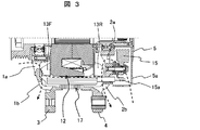
- FIG. 2 shows an example of a vehicular AC generator as a rotating electrical machine to which this embodiment can be applied.
- This figure has shown the longitudinal cross-sectional view of the alternating current generator for vehicles.
- a configuration of a typical rotating electrical machine to which the present embodiment can be applied will be described.
- a configuration in which a rectifier circuit, an IC regulator, a slip ring, a brush, and the like are arranged on the bottom surface portion of the rear bracket is adopted. Clarify what you are doing.
- the front bracket 1 and the rear bracket 2 have a bottomed cylindrical shape having an accommodation space inside, that is, a bowl shape. Further, the front bracket 1 and the rear bracket 2 are integrally provided with fixing portions 3 and 4 having fixing holes, respectively, projecting radially outward, and these fixing portions 3 and 4 are bolts (see FIG. (Not shown) is attached to the vehicle.
- the front bracket 1 and the rear bracket 2 are formed of an aluminum alloy, and die casting is used as a forming method.
- a rear cover 5 that is thinner than each bracket is attached to the end of the rear bracket 2 in the axial direction, and the rear cover 5 has a bottomed cylindrical shape having a housing space inside, that is, a bowl shape, like each bracket.
- the present invention relates to an improvement for fixing the rear cover 5 to the rotating electrical machine.
- the rear cover 5 has a plurality of air inlets 5a through which air flows.
- An output terminal 6 connected to the battery is attached to the outer peripheral side of the rear cover 5.
- the rear cover 5 is made of resin or aluminum alloy.
- Ball bearings 7a and 7b serving as bearings are respectively attached to the radial center positions of the front and rear brackets 1 and 2 at the axially outer ends.
- the ball bearings 7a attached to the front bracket 1 are A ball bearing having a diameter larger than that of the ball bearing 7b attached to the rear bracket 2 is used.
- a shaft 8 is inserted through the inner rings of these ball bearings 7a and 7b, and the shaft 8 is supported so as to be rotatable relative to the front bracket 1 and the rear bracket 2.
- a pulley 9 as a rotation transmitting member is fixed to the end of the shaft 8 on the side of the front bracket 1 so as to rotate integrally with a bolt, and a crank to which rotation of the engine (not shown) is transmitted is connected to the pulley 9.
- the rotation is transmitted from the pulley by the belt. For this reason, the shaft 8 rotates in proportion to the rotational speed of the engine and the pulley ratio of the pulley 9 and the crank pulley.
- slip rings 10 are attached to the end of the shaft 8 on the rear bracket 2 side so as to rotate integrally with the shaft 8, and two brushes that slide while being pressed against each slip ring 10. 11 is supplied with electric power.
- the slip ring 10 is disposed on the bottom surface portion of the rear bracket 2.
- the front-side rotor member 12F and the rear-side rotor member 12R formed of a magnetic material are serration-coupled separately at a substantially central portion in the rotation axis direction of the shaft 8 so as to rotate integrally with the shaft 8. Further, the front side rotor member 12F and the rear side rotor member 12R have shafts at the outer ends of the respective rotor members 12F and 12R so that the movement in the axial direction is restricted in a state where they are in contact with each other facing the axial direction. 8 is plastically flowed into the annular grooves 8a and 8b formed in the groove 8.
- the rotor 12 is constituted by the front rotor member 12F and the rear rotor member 12R fixed to the shaft 8.
- the plate-like fans 13F and 13R having a plurality of blades on the outer peripheral side are attached to both end faces in the rotation axis direction of the rotor 12, and rotate integrally with the rotor 12.
- the front-side rotor member 12F and the rear-side rotor member 12R include a shaft portion 12a located on the inner peripheral side and a plurality of rotor claw magnetic poles 12b having a radial cross section located on the outer peripheral side,
- a Landell-type iron core is configured by the axial ends of the shaft portions 12a of the rotor members 12F and 12R facing each other.
- a field winding 14 is wound around the rotating shaft between the outer periphery of the shaft portion 12a and the inner periphery of the rotor claw magnetic pole 12b, and both ends of the field winding 14 extend along the shaft 8 to extend as described above.
- Each is connected to a slip ring 10.
- a brush 11 supplies a field current via the slip ring 10 described above. As described above, the brush 11 is also disposed on the bottom surface of the rear bracket 2.
- the current supplied to the field winding 14 is controlled according to the state of the battery so as to start power generation when the power generation voltage becomes higher than the battery voltage of the vehicle, but the power generation voltage is adjusted.
- An IC regulator (not shown) as a voltage control circuit for this purpose is incorporated in a rectifier circuit 15 (described later) disposed inside the rear cover 5 and controls so that the terminal voltage of the output terminal 6 is always a constant voltage. .
- the stator 17 is fixed so as to be sandwiched between the front bracket 1 and the rear bracket 2, and the inner periphery faces the outer periphery of the rotor claw magnetic pole 12b of the rotor 12 with a slight gap.
- the stator 17 includes a stator core 17a made of a magnetic material, and an armature winding 17b wound along the stator core 17a.
- the armature winding 17b is provided in the rear cover 5. It is connected to the attached rectifier circuit 15. Further, the rectifier circuit 15 is connected to the battery via the output terminal 6.
- the rectifier circuit 15 is composed of a plurality of diodes, and these diodes constitute an independent three-phase coil, so that full-wave rectification is performed with six diodes.
- the rectifier circuit 15 is also arranged outside the bottom surface portion of the rear bracket 2.
- the IC regulator (not shown) is built in the rectifier circuit 15 disposed inside the rear cover 5, the IC regulator is also disposed outside the bottom surface portion of the rear bracket 2.
- the rectifier module including the IC regulator and the rectifier circuit 15 is disposed outside the bottom surface of the rear bracket 2, and this position is inside the rear cover 5 so that the rear cover 5 does not expose the outside. Covered with
- the front-side rotor member 12F and the rear-side rotor member 12R constituting the rotor 12 have a rotor claw magnetic pole 12b having an L-shaped radial section from the outer end in the axial direction of the shaft portion 12a.
- a plurality, specifically six, are provided in the direction. Since the rotor claw magnetic poles 12b extending from the front side rotor member 12F and the rear side rotor member 12R are alternately arranged in the circumferential direction, when all the rotor claw magnetic poles 12b are combined, 12 rotor claw magnetic poles are combined. 12b. That is, the number of magnetic poles of the rotor 12 in this embodiment is 12 poles.
- the front-side rotor member 12F and the rear-side rotor member 12R formed in this way are arranged so that the field windings 14 are disposed therebetween so that the rotor claw magnetic poles 12b are alternately positioned in the circumferential direction.
- the shaft portion 12a is fixed to the shaft 8 with the ends thereof in contact with each other.
- a front fan 13F and a rear fan 13R as cooling fans are attached to the outer ends in the axial direction of the front rotor member 12F and the rear rotor member 12R, respectively, by welding or the like.
- the front fan 13F and the rear fan 13R have a symmetrical fan arrangement so that air is circulated in the center direction by the rotation of the rotor 12.
- the front fan 13F will be described as an example.
- the metal plate having a plurality of protrusions formed in the circumferential direction is bent in the circumferential direction by a press in a substantially arc shape and substantially perpendicularly, and is inclined with respect to the radial direction.
- a blade having an inclined surface is integrally formed.
- the front fan 13F and the rear fan 13R formed in this way are integrally fixed to the outer ends in the axial direction of the front rotor member 12F and the rear rotor member 12R by welding or the like. An air flow can be created by the rotation of the rotor.
- the ventilation path is provided on the front bracket 1 side to cool internally by flowing from the air supply port 1 a provided on the front bracket 1 to the exhaust port 1 b, and is provided on the rear cover 5 on the rear bracket 2 side. Internal cooling is performed by flowing from the air supply port 5a to the exhaust port 2b of the rear bracket 2 via the air supply port 2a provided in the rear bracket 2.
- the air supply port 5a on the inner peripheral side provided in the rear cover 5 is located close to the brush 11 and the rectifier circuit 15, that is, on the shaft 8 side, so these are directly cooled.
- the stator core 17a is formed by laminating thin plates of magnetic material in a coil shape, and a plurality of slots (not shown) determined by the number of rotor claw magnetic poles 12b on the inner peripheral surface thereof. Are formed at an equal pitch.
- a pre-wound three-phase electromagnetic coil 17b is inserted into the slot and connected by Y connection or ⁇ connection.
- Insulating paper which is an insulating member, is inserted into the slot opening so that the electromagnetic winding 17b inserted into the slot is not exposed to the inner peripheral surface of the stator core 17a.
- the number of magnetic poles for one phase of the stator 17 is 12 poles, which is the same as the number of magnetic poles of the rotor 12.
- the surface of the armature winding 17b is covered with an insulating coating such as varnish, and the end of the armature winding 17b is connected between the rear bracket 2 and the terminal 15a of the rectifier circuit 15.
- position the insulating paper which is an insulating member between the stator core 17a and the armature winding 17b.
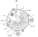
- FIG. 1 is a view of the rotating electrical machine viewed from the direction of arrow A in FIG. 2.
- the substantially circular rear cover 5 has a large number of air supply ports 5 a on the inner peripheral side and the outer peripheral side with the shaft 8 as the center. Is provided.
- the patterns drawn by these air supply ports 5 a can be various depending on the arrangement positions of the rectifier circuit 15, the IC regulator, the slip ring 10, the brush 11 and the like housed in the housing space inside the rear bracket 2.
- the first point of the device used for attachment to the rotating electrical machine is that engagement points with the rear bracket side are provided at a plurality of points on the bottomed cylindrical side wall portion of the rear cover 5, and the rear cover 5 is in the axial direction. It has been prevented from moving to.
- reference numeral 5 b denotes engagement openings provided at a plurality of locations around the rear cover 5, and the engagement claw 15 ⁇ / b> A ⁇ b> 1 on the other side of the rear bracket engages with the engagement opening 5 b. It fixes to a rotary electric machine and prevents that the rear cover 5 moves to an axial direction.
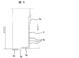
- FIG. 5 is a cross-sectional view of the rear cover 5
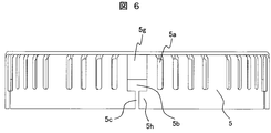
- FIG. 6 is a side view of the rear cover 5.
- a plurality of air inlets 5a for air to flow are provided in the side wall portion and the bottom wall portion of the rear cover 5.
- the rear cover 5 is provided with a plurality of engagement openings 5b on the same wall portion as the intake port of the side wall portion.
- the shape of the engagement opening 5b is such that the outer diameter ⁇ D51 of the side wall portion on the bottom wall side (right side in FIG. 5) of the rear cover 5 is the same as that of the side wall portion on the end surface opening side (left side in FIG. 5).
- a step is provided by making it smaller than the inner diameter ⁇ D52 ( ⁇ D51 ⁇ D52).
- the engagement portion 5g in FIG. 6 is formed at a position deeper than the engagement portion 5h.
- the engagement portion 5g and the engagement portion 5h are displaced from each other, so that the engagement of the engagement claw is further ensured.
- the rear cover made of resin or aluminum alloy can be easily made with a two-part mold.
- the opening on the end surface of the rear cover is opened, and the rear cover 5 can be easily attached and detached.
- the height of the rear cover 5 in the axial direction can be minimized. That is, when the rear cover 5 is packed, the volume when the rear cover 5 is stacked can be minimized, so that the loading quantity increases. As a result, the transportation efficiency can be improved, and the transportation cost can be kept low.
- Patent Document 1 the width of the rear cover in the axial direction is increased, and when the rear cover is stacked, a volume corresponding to the length of the engaging claw is required. That is, there has been a problem that the transportation cost increases due to a decrease in the number of packages at the time of packing and deterioration in transportation efficiency.
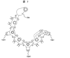
- an engaging claw 15 ⁇ / b> A ⁇ b> 1 for engaging the rear cover 5 with a mold terminal 15 ⁇ / b> A sandwiched between the positive diode and the negative diode of the rectifier circuit 15 for insulation is provided.
- the molded terminal 15A itself is a member formed along the outer peripheral portion of the rear bracket 2, and thus has a shape suitable for engagement at a plurality of points with the position of the through hole 5f as a locking point.
- it since it is made of an insulating material, electrical insulation between the rotating electrical machine and the rear cover 5 is achieved.
- FIG. 7 shows an example of the molded terminal 15A
- FIG. 8 shows a cross-sectional view of the engaging claw 15A1 portion.
- the mold terminal 15A shown in FIG. 7 has an engagement claw 15A1 attached to the position of the engagement opening 5b of the rear cover 5 shown in FIG.
- the surface of the engagement claw 15A1 that contacts the rear cover 5 is provided with a gradient (0 ⁇ ⁇ 1, 0 ⁇ ⁇ 2) from the outer periphery to the inner periphery of the engagement claw 15A1.
- the gradient provided in the engaging claw 15A1 absorbs the gap in the axial direction when the rear cover 5 is mounted, and it is possible to eliminate the interference sound generated by the rear cover 5 moving in the axial direction.
- This gradient may be provided on the surface of the engagement opening 5b provided in the rear cover 5 in contact with the engagement claw 15A1.
- the engaging claw 15A1 is provided with a gradient (0 ⁇ ⁇ 3) on the outer peripheral surface in the axial direction.
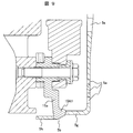
- FIG. 9 is an enlarged view of the lower right portion of FIG. 2, and the mold terminal 15 ⁇ / b> A shown in FIG. 8 is placed in the uneven space 5 b formed by 5 g and 5 h on the side wall portion of the rear cover 5 shown in FIG. 5. It can be seen that the pawl 15A1 is engaged.
- the positions of the through holes 5 f of the rear cover 5 are set as the locking points, and the engagement points with the rotating electrical machine side are provided at a plurality of points, and the engagement openings 5 b provided at a plurality of locations around the rear cover 5.
- the rear cover 5 is fixed to the rotating electrical machine by engaging with the engaging claw 15A1 on the rotating electrical machine side.
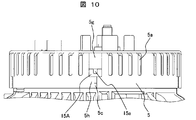
- FIG. 10 is a view of the rear cover 5 viewed from the direction of FIG. 6 in the engaged state, and it can be seen that the engaging claw 15A1 is sandwiched between the engaging portion 5g and the engaging portion 5h. Further, the shape of the engaging claw 15A1 in contact with the rear cover 5 is concave, and serves as an intake port 15a when the rear cover 5 is engaged.
- the second point of the device used for attachment to the rotating electrical machine is that it penetrates the bottom wall portion of the bottomed cylindrical rear cover 5 for the output terminal 6 of FIG. 2 connected to the external battery. It is the through-hole 5f provided.
- the relationship between the output terminal 6 and the through hole 5f is well represented in FIG.
- a screw 6a is cut to the output terminal 6 attached to the fin 15b of the positive-side diode of the rectifier circuit 15, and the vehicle-side current supply harness 18 is fixed with a bolt 6b.
- reference numeral 15d denotes a rotation-preventing convex portion provided on the fin 15b of the positive diode
- reference numeral 5d denotes a rotation-preventing concave portion.
- an insulating material is inserted between the rear cover and the fin 15b of the positive diode to ensure insulation.
- the fin 15b of the positive diode may be coated with an insulating coating.
- the rear cover 5 is not fixed with bolts 6b in this embodiment.
- the through hole 5f of the rear cover 5 is made to pass through the fin 15b of the positive side diode of the rectifier circuit 15 having a diameter slightly smaller than the diameter thereof, and the rear cover 5 is locked to the rotating electrical machine.
- the bolt 6b is fixed to the vehicle-side current supply harness 18 to the last. This prevents the rear cover 5 from moving in the circumferential direction due to vibration.
- Patent Document 1 a bolt and a spacer integrally formed on the rear cover are required for fixing the rear cover. This means that a bolt fastening facility and torque management at the time of bolt tightening are required at the time of manufacturing the rotating electrical machine, and there is a problem that the manufacturing cost increases.
- This embodiment is fixed only by the first device point, but by adopting a structure that also takes into account the second device point, it is possible to realize a more rigid fixing.
- the AC voltage thus generated is full-wave rectified by the rectifier circuit 15 and converted into a DC voltage.
- the current supplied to the field winding 14 is controlled by an IC regulator (not shown).
- the rear cover 5 is mounted so as to cover the rectifier circuit 15 and the IC regulator.
- the rear cover 5 is fixed by engaging openings provided on a side wall portion of the rear cover 5 with a plurality of engaging claws 15A provided on a mold terminal 15A sandwiched between a positive-side diode and a negative-side diode of a rectifier circuit.
- the rear cover 5 is fixed by engaging the portion 5b.
- the front fan 13F rotates to suck external air in the axial direction from the air inlet 1a provided in the outer peripheral portion of the ball bearing 7a in the front bracket 1, and the sucked air is generated by the blades of the front fan 13F.
- it flows to the outer peripheral side by centrifugal force, it is rectified as indicated by the broken line arrows in FIG. 2 and discharged from a plurality of exhaust ports 1 d provided in the circumferential direction on the outer peripheral portion of the front bracket 1.
- the pressure generated in the rear fan 13R increases, air flows from the front bracket 1 side to the rear bracket side through the gap between the rotor 12 and the stator 17 and between the rotor 12 magnetic poles, The rotor 12 and the stator 17 are cooled.
- vibration generated in the engine is transmitted to the AC generator.
- the generator itself is also vibrated by the magnetic excitation force generated by the rotation of the rotor.
- the direction of vibration generated in the generator occurs in an unspecified direction.
- vibrations are the radial vibrations F3 in the circumferential direction from the shaft 8 shown in FIG. 4, and the axial vibrations F2 in the direction of the shafts 8 are combined. For this reason, it is necessary for the fixing force of the rear cover 5 of the alternator to secure a strength that can withstand vibrations in an unspecified direction generated in the alternator.
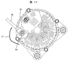
- the rear cover 5 needs to secure strength sufficient to withstand the force in the circumferential direction F1 generated when the vehicle-side current supply harness 18 shown in FIG. 11 is fixed.
- the generator is provided with an output terminal 6 for supplying current generated by the generator to the vehicle side.
- a bolt 6a is attached to the fin 15b of the positive diode and the bolt 6 is screwed with a screw 6a.
- a current supply harness 18 is set on the vehicle side to which current is supplied. The method of fixing the current supply harness 18 to the output terminal 6 of the generator is fixed by fastening a bolt 6a and a nut 6b.
- the protrusion 5e provided on the rear cover 5 is used as a rotation stop for the current supply harness 18, so that the circumferential force generated when the nut 6b is tightened.
- F1 is generated in the rear cover 5.
- the rear cover fixing method of Patent Document 1 has a structure in which a hook portion provided on an engagement claw of the rear cover is hooked on the generator main body side.
- the rear cover and the generator body are fixed by bolts and nuts.
- Patent Document 1 since the fixing point (contact portion) between the rear cover engaging claw and the generator main body was one, it was not possible to cope with vibration in an unspecified direction.
- the fixing point (contact portion) of the engaging claw restrains the upper, lower, left and right sides and the four sides. Further, by providing a plurality of engaging portions in the circumferential direction, the rear cover and the generator main body side are not separated from each other in response to vibrations in the axial direction F2, radial direction F1 and unspecified direction generated in the generator. No interference sound is generated.
- the vehicle-side current supply harness 18 is attached to the output terminal 6 portion of the generator, the vehicle-side current supply harness 18 is attached by using the rear cover rotation protrusion 5e, so that the output terminal 6 of the rear cover is attached. Generates a force in the circumferential direction F1. In order to cope with the force in the circumferential direction F1, the fins 15b of the positive-side diode constituting the output terminal 6 of the generator and the shapes of the holes provided in the rear cover were made uneven.
- the positive electrode side diode fin 15b constituting the generator output terminal 6 and the output terminal 6 can be fixed by engagement by an engagement claw. Further, the fixing force of the rear cover can be increased.
- the engaging claw provided on the generator main body side does not require elastic deformation, there is no restriction on the thickness of the engaging claw, and it is possible to set the thickness of the engaging claw necessary to ensure strength. Become.
- the engaging claw provided on the generator body side is made of a resin material (insulating material)
- the engaging claw is at the same potential as the rear cover. That is, there is an effect of preventing electric shock due to contact from the outside.
- an AC generator has been described as an example of a rotating electrical machine. However, this can be similarly realized with an electric motor or a DC machine.
- the output terminals that pass through the rear cover 5 and are taken out to the outside serve as terminals for supplying power, in general, these power terminals may be used for locking the rear cover 5.
Landscapes
- Engineering & Computer Science (AREA)
- Power Engineering (AREA)
- Synchronous Machinery (AREA)
- Motor Or Generator Frames (AREA)
Priority Applications (2)
| Application Number | Priority Date | Filing Date | Title |
|---|---|---|---|
| US13/697,422 US20130057121A1 (en) | 2010-05-26 | 2011-05-17 | Electrical rotating machine |
| CN2011800258554A CN102906975A (zh) | 2010-05-26 | 2011-05-17 | 旋转电机 |
Applications Claiming Priority (2)
| Application Number | Priority Date | Filing Date | Title |
|---|---|---|---|
| JP2010-120420 | 2010-05-26 | ||
| JP2010120420A JP5495945B2 (ja) | 2010-05-26 | 2010-05-26 | 回転電機 |
Publications (1)
| Publication Number | Publication Date |
|---|---|
| WO2011148825A1 true WO2011148825A1 (ja) | 2011-12-01 |
Family
ID=45003816
Family Applications (1)
| Application Number | Title | Priority Date | Filing Date |
|---|---|---|---|
| PCT/JP2011/061281 Ceased WO2011148825A1 (ja) | 2010-05-26 | 2011-05-17 | 回転電機 |
Country Status (4)
| Country | Link |
|---|---|
| US (1) | US20130057121A1 (enExample) |
| JP (1) | JP5495945B2 (enExample) |
| CN (1) | CN102906975A (enExample) |
| WO (1) | WO2011148825A1 (enExample) |
Families Citing this family (4)
| Publication number | Priority date | Publication date | Assignee | Title |
|---|---|---|---|---|
| JP5868531B1 (ja) * | 2015-01-20 | 2016-02-24 | 三菱電機株式会社 | 車両用回転電機 |
| WO2016185510A1 (ja) * | 2015-05-15 | 2016-11-24 | 三菱電機株式会社 | 車両用交流発電機 |
| JP6503588B2 (ja) * | 2015-10-05 | 2019-04-24 | 多摩川精機株式会社 | 樹脂一体成形型レゾルバステータ構造 |
| CN108336838A (zh) * | 2017-01-20 | 2018-07-27 | 德昌电机(深圳)有限公司 | 电机 |
Citations (6)
| Publication number | Priority date | Publication date | Assignee | Title |
|---|---|---|---|---|
| JPS59169354A (ja) * | 1983-03-15 | 1984-09-25 | Nippon Denso Co Ltd | 車両用交流発電機 |
| JPH07336974A (ja) * | 1994-06-10 | 1995-12-22 | Sawafuji Electric Co Ltd | オルタネータ |
| JP2002095215A (ja) * | 2000-09-14 | 2002-03-29 | Sawafuji Electric Co Ltd | 車両用交流発電機 |
| JP2003527061A (ja) * | 2000-03-10 | 2003-09-09 | ヴァレオ エキプマン エレクトリク モトゥール | 多相回転電気機器 |
| JP2004248338A (ja) * | 2003-02-10 | 2004-09-02 | Denso Corp | 車両用交流発電機 |
| JP2009005419A (ja) * | 2007-06-19 | 2009-01-08 | Hitachi Ltd | 回転電機 |
Family Cites Families (3)
| Publication number | Priority date | Publication date | Assignee | Title |
|---|---|---|---|---|
| FR2732524B1 (fr) * | 1995-04-03 | 1997-05-09 | Valeo Thermique Habitacle | Dispositif de fixation elastique d'un moteur electrique a l'interieur d'un boitier, notamment pour vehicule automobile |
| CN101222158A (zh) * | 2007-12-21 | 2008-07-16 | 上海电器科学研究所(集团)有限公司 | 降低电机结构噪声的“o”型橡胶密封圈结构 |
| CN201315515Y (zh) * | 2008-12-04 | 2009-09-23 | 开平市三威微电机有限公司 | 一种改进后端盖轴承座结构的电动机 |
-
2010
- 2010-05-26 JP JP2010120420A patent/JP5495945B2/ja not_active Expired - Fee Related
-
2011
- 2011-05-17 CN CN2011800258554A patent/CN102906975A/zh active Pending
- 2011-05-17 WO PCT/JP2011/061281 patent/WO2011148825A1/ja not_active Ceased
- 2011-05-17 US US13/697,422 patent/US20130057121A1/en not_active Abandoned
Patent Citations (6)
| Publication number | Priority date | Publication date | Assignee | Title |
|---|---|---|---|---|
| JPS59169354A (ja) * | 1983-03-15 | 1984-09-25 | Nippon Denso Co Ltd | 車両用交流発電機 |
| JPH07336974A (ja) * | 1994-06-10 | 1995-12-22 | Sawafuji Electric Co Ltd | オルタネータ |
| JP2003527061A (ja) * | 2000-03-10 | 2003-09-09 | ヴァレオ エキプマン エレクトリク モトゥール | 多相回転電気機器 |
| JP2002095215A (ja) * | 2000-09-14 | 2002-03-29 | Sawafuji Electric Co Ltd | 車両用交流発電機 |
| JP2004248338A (ja) * | 2003-02-10 | 2004-09-02 | Denso Corp | 車両用交流発電機 |
| JP2009005419A (ja) * | 2007-06-19 | 2009-01-08 | Hitachi Ltd | 回転電機 |
Also Published As
| Publication number | Publication date |
|---|---|
| US20130057121A1 (en) | 2013-03-07 |
| JP2011250562A (ja) | 2011-12-08 |
| JP5495945B2 (ja) | 2014-05-21 |
| CN102906975A (zh) | 2013-01-30 |
Similar Documents
| Publication | Publication Date | Title |
|---|---|---|
| JP4156542B2 (ja) | 車両用回転電機装置 | |
| JP6433585B2 (ja) | 車両用交流発電機 | |
| JP3949368B2 (ja) | 車両用交流発電機 | |
| JP4389918B2 (ja) | 回転電機及び交流発電機 | |
| JP2011004501A (ja) | 回転電機 | |
| JP2009148057A (ja) | 車両用交流発電機 | |
| JPS62221839A (ja) | 自動車用交流発電機 | |
| US8933599B2 (en) | Cooling system of electric rotating machine for vehicles | |
| JP3098223B2 (ja) | 車両用交流発電機 | |
| CN108352771A (zh) | 交流发电机 | |
| KR100874317B1 (ko) | 차량용 교류 발전기 | |
| JP2008289244A (ja) | 回転電機の冷却構造 | |
| JP5495945B2 (ja) | 回転電機 | |
| JP4575385B2 (ja) | 交流発電機の整流器 | |
| US7800261B2 (en) | Rotary electric machine with stator outer surface designed to enhance heat dissipation | |
| CN107996016A (zh) | 车用旋转电机 | |
| US9225219B2 (en) | Dynamoelectric machine | |
| CN107078604A (zh) | 车用交流发电机 | |
| JP4400577B2 (ja) | ブラシレス車両用交流発電機 | |
| JP2007336723A (ja) | 回転電機の回転子 | |
| US12388318B2 (en) | Cover for a rotating electric machine | |
| JP2004282937A (ja) | 車両用交流発電機 | |
| JP6336178B1 (ja) | 車両用回転電機の回転子 | |
| JP2007104800A (ja) | 車両用回転電機 | |
| JP2010041850A (ja) | 回転電機 |
Legal Events
| Date | Code | Title | Description |
|---|---|---|---|
| WWE | Wipo information: entry into national phase |
Ref document number: 201180025855.4 Country of ref document: CN |
|
| 121 | Ep: the epo has been informed by wipo that ep was designated in this application |
Ref document number: 11786524 Country of ref document: EP Kind code of ref document: A1 |
|
| DPE1 | Request for preliminary examination filed after expiration of 19th month from priority date (pct application filed from 20040101) | ||
| WWE | Wipo information: entry into national phase |
Ref document number: 13697422 Country of ref document: US |
|
| NENP | Non-entry into the national phase |
Ref country code: DE |
|
| 122 | Ep: pct application non-entry in european phase |
Ref document number: 11786524 Country of ref document: EP Kind code of ref document: A1 |