WO2011145355A1 - 照明装置およびそれを備えた表示装置 - Google Patents
照明装置およびそれを備えた表示装置 Download PDFInfo
- Publication number
- WO2011145355A1 WO2011145355A1 PCT/JP2011/050414 JP2011050414W WO2011145355A1 WO 2011145355 A1 WO2011145355 A1 WO 2011145355A1 JP 2011050414 W JP2011050414 W JP 2011050414W WO 2011145355 A1 WO2011145355 A1 WO 2011145355A1
- Authority
- WO
- WIPO (PCT)
- Prior art keywords
- diffusion plate
- fixing
- plate fixing
- lighting device
- fixing portion
- Prior art date
- Legal status (The legal status is an assumption and is not a legal conclusion. Google has not performed a legal analysis and makes no representation as to the accuracy of the status listed.)
- Ceased
Links
Images





Classifications
-
- G—PHYSICS
- G02—OPTICS
- G02F—OPTICAL DEVICES OR ARRANGEMENTS FOR THE CONTROL OF LIGHT BY MODIFICATION OF THE OPTICAL PROPERTIES OF THE MEDIA OF THE ELEMENTS INVOLVED THEREIN; NON-LINEAR OPTICS; FREQUENCY-CHANGING OF LIGHT; OPTICAL LOGIC ELEMENTS; OPTICAL ANALOGUE/DIGITAL CONVERTERS
- G02F1/00—Devices or arrangements for the control of the intensity, colour, phase, polarisation or direction of light arriving from an independent light source, e.g. switching, gating or modulating; Non-linear optics
- G02F1/01—Devices or arrangements for the control of the intensity, colour, phase, polarisation or direction of light arriving from an independent light source, e.g. switching, gating or modulating; Non-linear optics for the control of the intensity, phase, polarisation or colour
- G02F1/13—Devices or arrangements for the control of the intensity, colour, phase, polarisation or direction of light arriving from an independent light source, e.g. switching, gating or modulating; Non-linear optics for the control of the intensity, phase, polarisation or colour based on liquid crystals, e.g. single liquid crystal display cells
- G02F1/133—Constructional arrangements; Operation of liquid crystal cells; Circuit arrangements
- G02F1/1333—Constructional arrangements; Manufacturing methods
- G02F1/1335—Structural association of cells with optical devices, e.g. polarisers or reflectors
- G02F1/1336—Illuminating devices
- G02F1/133602—Direct backlight
- G02F1/133606—Direct backlight including a specially adapted diffusing, scattering or light controlling members
-
- G—PHYSICS
- G02—OPTICS
- G02F—OPTICAL DEVICES OR ARRANGEMENTS FOR THE CONTROL OF LIGHT BY MODIFICATION OF THE OPTICAL PROPERTIES OF THE MEDIA OF THE ELEMENTS INVOLVED THEREIN; NON-LINEAR OPTICS; FREQUENCY-CHANGING OF LIGHT; OPTICAL LOGIC ELEMENTS; OPTICAL ANALOGUE/DIGITAL CONVERTERS
- G02F1/00—Devices or arrangements for the control of the intensity, colour, phase, polarisation or direction of light arriving from an independent light source, e.g. switching, gating or modulating; Non-linear optics
- G02F1/01—Devices or arrangements for the control of the intensity, colour, phase, polarisation or direction of light arriving from an independent light source, e.g. switching, gating or modulating; Non-linear optics for the control of the intensity, phase, polarisation or colour
- G02F1/13—Devices or arrangements for the control of the intensity, colour, phase, polarisation or direction of light arriving from an independent light source, e.g. switching, gating or modulating; Non-linear optics for the control of the intensity, phase, polarisation or colour based on liquid crystals, e.g. single liquid crystal display cells
- G02F1/133—Constructional arrangements; Operation of liquid crystal cells; Circuit arrangements
- G02F1/1333—Constructional arrangements; Manufacturing methods
- G02F1/133308—Support structures for LCD panels, e.g. frames or bezels
- G02F1/133322—Mechanical guidance or alignment of LCD panel support components
Definitions
- the present invention relates to a lighting device and a display device including the same.
- a liquid crystal display panel that displays an image does not emit light. Therefore, a backlight unit is provided on the back side of the liquid crystal display panel (the side opposite to the display surface side of the liquid crystal display panel). An illuminating device called is installed, and a display operation is performed by illuminating the back surface of the liquid crystal display panel with the backlight unit.
- a light source is disposed in a region directly below the liquid crystal display panel (a region facing the back surface of the liquid crystal display panel), and a diffusion plate is disposed between the light source and the liquid crystal display panel. Is further arranged, and the light generated by the light source is diffused by the diffusion plate so that the light from the light source is spread over the entire effective display area (see, for example, Patent Document 1).
- the diffusion plate is fixed by pressing the outer edge portion (the portion corresponding to the non-display area) of the diffusion plate with a casing.
- this diffusion plate fixing method it cannot be said that the diffusion plate is firmly fixed, and the diffusion plate is likely to be displaced. If the diffusion plate is displaced, the diffusion plate may drop off from a desired installation location, or luminance unevenness may occur.
- a method of fixing the diffusion plate with a double-sided tape is also conceivable.
- the adhesive strength of the double-sided tape is reduced in a low temperature or high humidity environment. For this reason, even if the diffusion plate is fixed with the double-sided tape, the diffusion plate may be displaced in some cases.
- This invention was made in order to solve the said subject, and it aims at providing the illuminating device which can suppress the position shift of a diffuser plate, and a display apparatus provided with the same.
- an illumination device has a light incident surface and a light emitting surface opposite to the light incident surface, and diffuses light incident on the light incident surface.
- a diffusion plate that emits light from the light exit surface and a fixing member that fixes the diffusion plate are provided.
- the diffuser plate fixing portion consisting of a concave portion or a convex portion is provided in a predetermined portion on the light exit surface side of the diffuser plate, and the diffuser plate A fixing member is engaged with the fixing portion.
- the diffuser plate fixing portion is formed of a recess, the recess may be a through hole or may not pass through.
- the fixing member since the fixing member is engaged with the diffusion plate fixing portion, the unintended movement and deformation of the diffusion plate are restricted by the configuration as described above. That is, the diffuser plate is firmly fixed, and the diffuser plate is hardly displaced. And if it becomes like this, drop-off
- an opening for exposing the diffusion plate fixing portion may be formed in the optical sheet.
- the optical sheet can be fixed.
- the diffusion plate is held by a casing, and a fixing member is provided in a part of the casing.
- a fixing member is provided in a part of the casing (member that holds the diffusion plate), it becomes easy to engage the fixing member with the diffusion plate fixing portion.
- the diffusion plate fixing portion may be a concave portion, and a pin-like member that can be inserted into the diffusion plate fixing portion may be a fixing member. If comprised in this way, it can be made into the state by which the diffuser plate fixing
- the diffusion plate fixing portion is formed of a concave portion, when viewed in plan from the light incident surface side of the diffusion plate, the diffusion plate fixing portion is also provided in a predetermined portion on the light incident surface side of the diffusion plate. It is preferable. If comprised in this way, the engagement area of a diffusion plate fixing
- the diffusion plate fixing portion is a through-hole penetrating from the light emitting surface side of the diffusion plate toward the light incident surface side. If comprised in this way, a firmer diffusion plate can be easily fixed by making a fixing member penetrate completely to a diffusion plate fixing
- the fixing member may be a tapered pin-shaped member. If such a fixing member (tapered pin-shaped member) is inserted into the diffusion plate fixing portion (a concave portion including a through hole), a wedge is driven into the diffusion plate fixing portion. It will be very strong.
- the diffusion plate fixing portion may be a convex portion, and an insertion portion into which the diffusion plate fixing portion can be inserted may be formed on the fixing member. If comprised in this way, a diffuser plate fixing
- the diffusion plate fixing portion includes a plurality of diffusion plate fixing portions. If comprised in this way, the diffusion plate can be firmly fixed.
- the diffusion plate fixing portion includes a plurality of diffusion plate fixing portions
- the planar shape of the diffusion plate is a quadrangular shape
- the outer edges of a pair of side sides parallel to each other of the light emission surfaces of the diffusion plate It is preferable that at least one diffusion plate fixing portion is disposed in each of the portions.
- the diffusion plate can be firmly fixed with good balance.
- two or more diffusing plate fixing portions are provided on each of the outer edge portions of the pair of side sides parallel to each other of the light emitting surface of the diffusing plate (for example, More preferably, three are arranged.
- the diffusion plate In a configuration in which a diffusion plate fixing portion is disposed on each of the pair of parallel outer side edge portions of the light emission surface of the diffusion plate, the diffusion plate is fixed on the outer edge portion on one side of the light emission surface of the diffusion plate.
- the arrangement position of the part and the arrangement position of the diffusion plate fixing part in the outer edge part on the other side may be shifted from each other. If comprised in this way, the front and back of a diffusion plate can be discriminate
- the engagement area of the predetermined diffusion plate fixing portion among the plurality of diffusion plate fixing portions with respect to the fixing member is a fixing member of another diffusion plate fixing portion. It may be larger than the engagement area.
- the fixing member or the diffusion plate fixing portion may be movable, and the fixing member or the diffusion plate fixing portion may be moved in a direction of pulling the diffusion plate. If comprised in this way, it will be in the state by which the tensile stress was applied to the diffusion plate, and, thereby, fixation of a diffusion plate becomes firmer.
- a display device includes the illumination device according to the first aspect and a display panel illuminated by the illumination device.
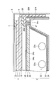
- FIG. 3 is a partial cross-sectional view of the backlight unit according to the first embodiment.
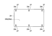
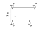
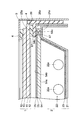
- FIG. 3 is a plan view of a diffusion plate provided in the backlight unit shown in FIG. 2. It is a top view of the diffusion plate with which the backlight unit by the modification of 1st Embodiment is equipped. It is a top view of the diffusion plate with which the backlight unit by the modification of 1st Embodiment is equipped. It is a top view of the diffusion plate with which the backlight unit by the modification of 1st Embodiment is equipped. It is sectional drawing of a part of backlight unit by 2nd Embodiment.
- FIG. 3 is a partial cross-sectional view of the backlight unit according to the first embodiment.
- FIG. 3 is a plan view of a diffusion plate provided in the backlight unit shown in FIG. 2. It is a top view of the diffusion plate with which the backlight unit by the modification of 1st Embodiment is equipped. It is a top view of the diffusion plate with which the
- FIG. 6 is a partial cross-sectional view of a backlight unit according to a third embodiment.
- FIG. 6 is a partial cross-sectional view of a backlight unit according to a fourth embodiment. It is a top view of the diffusion plate with which the backlight unit by a 5th embodiment is equipped. It is a figure for demonstrating the fixing method of the diffusion plate shown in FIG. It is a figure for demonstrating the fixing method of the diffusion plate shown in FIG. It is sectional drawing of a part of backlight unit by 6th Embodiment. It is a top view for demonstrating the arrangement position and planar shape of the diffusion plate fixing
- This display device is a liquid crystal display device.
- a liquid crystal display panel 1 and a backlight unit 2 installed on the back surface side opposite to the display surface side of the liquid crystal display panel 1.
- the display surface of the liquid crystal display panel 1 is exposed from the opening of the bezel 3 that is one of the housings. Then, the optical property (light transmittance) of the liquid crystal display panel 1 is changed for each pixel, and the back surface of the liquid crystal display panel 1 is illuminated with the light from the backlight unit 2. A desired image is displayed on the display screen.
- the liquid crystal display panel 1 is an example of the “display panel” in the present invention
- the backlight unit 2 is an example of the “illuminating device” in the present invention.
- the liquid crystal display panel 1 includes a liquid crystal layer (not shown), a pair of transparent substrates (active matrix substrate and counter substrate) 11, a polarizing plate 12, and the like.
- the liquid crystal layer is sandwiched between a pair of transparent substrates 11, and polarizing plates 12 are respectively disposed on surfaces of the pair of transparent substrates 11 opposite to the liquid crystal layer side.
- the inner area surrounded by the broken line in FIG. 1 is an effective display area (area where a plurality of pixels are arranged in a matrix), and the outer area other than the effective display area is a non-display area. .
- the backlight unit 2 includes a back chassis 21, a light source module 22, a reflection sheet 23, a diffusion plate 24, an optical sheet 25, a frame 26, and the like.
- the back chassis 21 and the frame 26 are examples of the “housing” of the present invention.
- the light source module 22 is an example of the “light source” in the present invention.
- the back chassis 21 has a concave shape, and has a bottom portion and side portions erected on the outer edge of the bottom portion. And the area
- the planar shape of the accommodation area of the back chassis 21 is a quadrangular shape.
- a flat portion 21 a is formed near the upper end of the side portion of the back chassis 21, and a part of the diffusion plate 24 is placed on the flat portion 21 a of the back chassis 21.
- the light source module 22 includes a plurality of discharge tubes 22 a and is accommodated in an accommodation area of the back chassis 21.
- the light source module 22 generates light for illuminating the liquid crystal display panel 1.
- the reflection sheet 23 is disposed along the inner surface (the bottom surface of the bottom portion and the inner surface of the side portion) of the back chassis 22. That is, the inner surface of the back chassis 22 is a light reflecting surface by the reflecting sheet 23. Thereby, when the light generated by the light source module 22 is incident on the inner surface of the back chassis 22, the light is reflected toward the liquid crystal display panel 1 side without being absorbed.
- the diffuser plate 24 is made of a plate member having a quadrangular planar shape, and is a plane facing the back chassis 21 (hereinafter referred to as a light incident surface 24a) and a surface opposite to the light incident surface 24a, which is a liquid crystal display. It has at least a plane directed to the panel 1 side (hereinafter referred to as the light exit surface 24b).
- the light source module 22 is covered by the diffusion plate 24 from the liquid crystal display panel 1 side. Thereby, the light generated by the light source module 22 is incident on the light incident surface 24a of the diffusion plate 24 and diffused, and is emitted from the light emission surface 24b of the diffusion plate 24 toward the liquid crystal display panel 1 side.
- the diffusion plate 24 is mounted on the flat portion 21a of the back chassis 21 so that the outer edge portion (the portion corresponding to the non-display area) covers the light source module 22 from the liquid crystal display panel 1 side. Is retained.
- the optical sheet 25 is made of a sheet member having a square planar shape, and includes a diffusion sheet, a lens sheet, and the like.
- the optical sheet 25 is placed on the light emission surface 24b of the diffusion plate 24, and diffuses or collects light emitted from the light emission surface 24b of the diffusion plate 24.
- the frame 26 has a frame shape integrally including a frame portion 26a.
- the frame portion 26a of the frame 26 is disposed on the outer edge portion of the diffusion plate 24 (optical sheet 25) and presses the outer edge portion of the diffusion plate 24 (optical sheet 25). That is, the outer edge portion of the diffusion plate 24 (optical sheet 25) is sandwiched between the flat portion 21a of the back chassis 21 and the frame portion 26a of the frame 26.
- the liquid crystal display panel 1 has an outer edge portion sandwiched between a pair of cushion materials 4.
- FIGS. 2 and 3 when viewed from the light exit surface 24 b side of the diffuser plate 24, the outer edge portion (back chassis) of the diffuser plate 24 on the light exit surface 24 b side is shown. 21 (a portion sandwiched between the flat portion 21a of the frame 21 and the frame portion 26a of the frame 26). Further, when viewed in plan from the light incident surface 24 a side of the diffusion plate 24, a concave portion is also formed in the outer edge portion of the diffusion plate 24 on the light incident surface 24 a side.
- the recessed part formed in the outer edge part by the side of the light-projection surface 24b of the diffusion plate 24 and the recessed part formed in the outer edge part by the side of the light-incidence surface 24a are mutually connected in the plate
- a through-hole penetrating from the light emitting surface 24b side to the light emitting surface 24a side is formed in the outer edge portion of the diffusion plate 24 on the light emitting surface 24b side. And the through-hole of the diffusion plate 24 is made into the diffusion plate fixing
- the diffusion plate fixing portions (through holes) 24c of the diffusion plate 24 are arranged one by one (four in total) at each corner of the light emission surface 24b when viewed in plan from the light emission surface 24b side. Yes. That is, two diffusion plate fixing portions (through holes) 24c are disposed on each of the pair of parallel outer side edge portions of the light emitting surface 24b of the diffusion plate 24, and the diffusion plate at the outer edge portion on one side side.
- the arrangement position of the fixing part (through hole) 24c and the arrangement position of the diffusion plate fixing part (through hole) 24c in the outer edge part on the other side are symmetrical.
- the planar shapes of the plurality of diffusion plate fixing portions (through holes) 24c of the diffusion plate 24 are all the same.
- an opening 25a is formed in the optical sheet 25, and the opening 25a of the optical sheet 25 is disposed at a portion overlapping the diffusion plate fixing portion (through hole) 24c of the diffusion plate 24. For this reason, the optical sheet 25 is placed on the light exit surface 24 b of the diffusion plate 24, but the diffusion plate fixing portion (through hole) 24 c of the diffusion plate 24 is exposed through the opening 25 a of the optical sheet 25. Has been.
- the fixing pin 27 is inserted into the diffusion plate fixing portion (through hole) 24c of the diffusion plate 24 (including press-fitting), and the diffusion plate fixing portion (through hole) 24c of the diffusion plate 24 and the fixing pin are inserted. 27, the outer edge portion of the diffusion plate 24 is fixed.
- the fixing pin 27 is an example of the “fixing member” and the “pin-shaped member” in the present invention.
- the fixing pin 27 has an engaging portion formed in a cylindrical shape, and the opening shape of the diffusion plate fixing portion (through hole) 24 c of the diffusion plate 24 is the same as that of the engaging portion of the fixing pin 27.
- the shape corresponds to the shape (circular shape).
- a cylindrical engaging portion of the fixing pin 27 is inserted into a diffusion plate fixing portion (through hole) 24 c opened in a circular shape of the diffusion plate 24.
- the fixing pin 27 inserted into the diffusion plate fixing portion (through hole) 24c of the diffusion plate 24 completely penetrates the diffusion plate 24 in the plate thickness direction. That is, the lower end portion of the fixing pin 27 (the portion on the flat portion 21a side of the back chassis 21) is exposed to the light incident surface 24a side from the diffusion plate fixing portion (through hole) 24c of the diffusion plate 24, and the back chassis 21 is flat. It has reached part 21a. Further, the upper end portion of the fixing pin 27 (the portion on the frame portion 26a side of the frame 26) is exposed from the diffusion plate fixing portion (through hole) 24c of the diffusion plate 24 to the light emitting surface 24b side. It reaches the frame portion 26a of the frame 26 through the opening 25a.
- the fixing pin 27 may be retrofitted to the flat portion 21a of the back chassis 21 or may be integrated with the flat portion 21a of the back chassis 21. Further, the fixing pin 27 may be retrofitted to the frame portion 26 a of the frame 26, or the fixing pin 27 may be integrated with the frame portion 26 a of the frame 26.
- the fixing pin 27 is engaged with the diffusion plate fixing portion 24c of the diffusion plate 24 by the configuration as described above, unintended movement and deformation of the diffusion plate 24 are restricted. That is, the diffusion plate 24 is firmly fixed, and the position of the diffusion plate 24 is not easily displaced. And if it becomes like this, drop-off
- the opening 25 a is formed in the optical sheet 25 placed on the light emitting surface 24 b of the diffusion plate 24, and the diffusion plate 24 is formed from the opening 25 a of the optical sheet 25. Even if the optical sheet 25 is placed on the light emitting surface 24b of the diffusion plate 24 by exposing the diffusion plate fixing portion 24c, the fixing pin 27 is engaged with the diffusion plate fixing portion 24c of the diffusion plate 24. Can do. Further, the optical sheet 25 can be fixed.
- the fixing pin 27 is provided on either the flat portion 21a of the back chassis 21 or the frame portion 26a of the frame 26, thereby fixing the diffusion plate 24 to the diffusion plate fixing portion 24c. It becomes easy to engage the pin 27.
- the diffusion plate fixing portion 24c of the diffusion plate 24 is formed as a through hole so that the fixing pin 27 is inserted into the diffusion plate fixing portion 24c of the diffusion plate 24.
- the diffusion plate fixing portion 24c of the diffusion plate 24 and the fixing pin 27 can be engaged. Further, by completely passing the fixing pin 27 through the diffusion plate fixing portion 24c of the diffusion plate 24, the engagement area between the diffusion plate fixing portion 24c and the fixing pin 27 of the diffusion plate 24 is increased, so that stronger diffusion is achieved.
- the plate 24 can be easily fixed.
- two diffusion plate fixing portions 24c are disposed on each of the pair of side edge sides parallel to each other of the light emission surface 24b of the diffusion plate 24, thereby diffusing.
- the plate 24 can be firmly fixed with good balance.
- one diffusion plate fixing portion 24 c is added to each of the pair of parallel outer side edge portions of the light emitting surface 24 b of the diffusion plate 24. Further, the added diffusion plate fixing portion 24c may be disposed near the center of the outer edge portions of the pair of side surfaces parallel to each other of the diffusion plate 24. Thereby, fixation in the center part of the diffusion plate 24 is ensured. Therefore, the configuration of this modification is effective when using a large diffusing plate 24 whose central portion is easily bent.
- the arrangement positions of the diffusion plate fixing portions 24c may be shifted from each other. Thereby, the front and back of the diffusion plate 24 can be discriminated from the arrangement position of the diffusion plate fixing portion 24c of the diffusion plate 24. Therefore, the front and back of the diffusion plate 24 are less likely to be mistaken during assembly work.
- the opening area of a predetermined diffusion plate fixing portion 24c among the plurality of diffusion plate fixing portions 24c of the diffusion plate 24 is set to be different from that of the other diffusion plate fixing portions 24c.
- the diameter of the fixing pin 27 inserted into the predetermined diffusion plate fixing portion 24c of the diffusion plate 24 may be further increased in accordance with the opening area. That is, the area of engagement of the predetermined diffusion plate fixing part 24c of the diffusion plate 24 with the fixing pin 27 may be larger than the area of engagement of the other diffusion plate fixing part 24c with the fixing pin 27.
- a housing fixing screw used for fixing the housing may be engaged with the diffusion plate fixing portion 24c of the diffusion plate 24. That is, the “fixing member” of the present invention may be a fixing screw for a housing.
- a diffusion plate 34 having the same function as that of the diffusion plate 24 (see FIG. 2) of the first embodiment is used, but its fixing method is different from that of the first embodiment.
- the concave portion formed on the light emitting surface 34b side of the diffusion plate 34 is a diffusion plate fixing portion 34c. That is, the diffusion plate fixing portion (concave portion) 34c of the diffusion plate 34 does not penetrate in the thickness direction.
- the diffusion plate fixing portion (concave portion) 34c of the diffusion plate 34 it is preferable that it is the same as 1st Embodiment or its modification.
- the flat portion 26 a of the frame 26 is provided with a fixing pin 37 (corresponding to “fixing member” and “pin-shaped member” of the present invention). It is inserted (including press-fitting) into the diffusion plate fixing part (concave part) 34c. Thereby, the diffusion plate fixing portion (concave portion) 34c of the diffusion plate 34 and the fixing pin 37 are engaged, and the outer edge portion of the diffusion plate 34 is fixed.
- the engagement area between the diffusion plate fixing portion 34c of the diffusion plate 34 and the fixing pin 37 is smaller than that in the first embodiment, but substantially the same effect as the first embodiment is obtained. can get.
- the diffusion plate fixing portion is not formed on the outer edge portion on the light incident surface 34a side of the diffusion plate 34, but only on the outer edge portion on the light emitting surface 34b side of the diffusion plate 34.
- a diffusion plate 44 having the same function as that of the diffusion plate 24 (see FIG. 2) of the first embodiment is used, but its fixing method is different from that of the first embodiment.
- a through hole having an opening width gradually narrowed from the light incident surface 44a side toward the light emitting surface 44b side is formed in the outer edge portion of the diffusion plate 44,
- a through hole formed in the outer edge portion of the diffusion plate 44 serves as a diffusion plate fixing portion 44c.
- fixed part (through-hole) 44c of the diffusion plate 44 it is preferable that it is the same as 1st Embodiment or its modification.
- the fixing pin 47 is provided on the flat portion 21a of the back chassis 21, and the fixing pin 47 extends from the base end portion (the portion on the flat portion 21a side of the back chassis 21) toward the tip end portion. It has a tapered shape (substantially conical shape). That is, the fixing pin 47 functions as a wedge.
- the fixing pin 47 is an example of the “fixing member” and the “pin-shaped member” in the present invention.
- the fixing pin 47 is inserted (including press-fitting) into the diffusion plate fixing portion (through hole) 44c of the diffusion plate 44.
- the fixing pin 47 has a wedge shape, A wedge is driven into a diffusion plate fixing portion (through hole) 44 c of the diffusion plate 44. Thereby, the diffusion plate fixing portion (through hole) 44c of the diffusion plate 44 and the fixing pin 47 are engaged, and the outer edge portion of the diffusion plate 44 is fixed.
- a diffusion plate 54 having the same function as that of the diffusion plate 24 (see FIG. 2) of the first embodiment is used, but its fixing method is different from that of the first embodiment.
- recesses are formed in both the outer edge portion on the light incident surface 54a side and the outer edge portion on the light emission surface 54b side of the diffusion plate 54.
- the concave portion on the surface 54a side and the concave portion on the light emitting surface 54b side are not connected to each other in the plate thickness direction and do not form a through hole.
- the concave portion on the light incident surface 54a side of the diffusion plate 54 is gradually narrowed as the opening width thereof is separated from the light incident surface 54a, and the concave portion on the light emission surface 54b side of the diffuser plate 54 is the opening width thereof. Is gradually narrowed away from the light exit surface 54b.
- the concave portions on the light incident surface 54a side and the concave portions on the light emitting surface 54b side of the diffuser plate 54 serve as the diffuser plate fixing portion 54c.
- the arrangement position of the diffusion plate fixing portion (concave portion) 54c of the diffusion plate 54 is preferably the same as that in the first embodiment or its modification.
- fixing pins 57 are provided on both the flat portion 21a of the back chassis 21 and the frame portion 26a of the frame 26, and these fixing pins 57 function as wedges. That is, the fixing pin 57 provided on the flat portion 21a of the back chassis 21 has a tapered shape (substantially conical shape) from the base end portion (the portion on the flat portion 21a side of the back chassis 21) toward the distal end portion. At the same time, the fixing pin 57 provided on the frame portion 26a of the frame 26 has a tapered shape (substantially conical shape) from the base end portion (the portion on the frame portion 26a side of the frame 26) toward the distal end portion.
- the fixing pin 57 is an example of the “fixing member” and the “pin-shaped member” in the present invention.
- the fixing pin 57 provided on the flat portion 21a of the back chassis 21 is inserted (including press-fitting) into the diffusion plate fixing portion (concave portion) 54c on the light incident surface 54a side of the diffusion plate 54
- a fixing pin 57 provided on the frame portion 26a of the frame 26 is inserted (including press-fitting) into a diffusion plate fixing portion (concave portion) 54c on the light emitting surface 54b side of the diffusion plate 54.
- the wedges are driven into both the diffusion plate fixing portion (recessed portion) 54c on the light incident surface 54a side and the diffusion plate fixing portion (recessed portion) 54c on the light emitting surface 54b side of the diffusion plate 54.
- the fixing pin 57 is engaged with both the diffusion plate fixing portion (recessed portion) 54c on the light incident surface 54a side and the diffusion plate fixing portion (recessed portion) 54c on the light emitting surface 54b side of the diffusion plate 54.
- the outer edge of is fixed.
- the fixing pin 57 is tapered, so that the wedge is driven into the diffusion plate fixing portion 54c of the diffusion plate 54 as in the third embodiment.
- the fixation of the diffusion plate 54 becomes very strong.
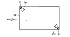
- a diffusion plate 64 as shown in FIG. 10 is used. Specifically, a diffusion plate fixing portion (a concave portion including a through hole) 64c is formed on an outer edge portion of at least the light exit surface 64b side of the light incident surface 64a and the light exit surface 64b of the diffuser plate 64. One diffusion plate fixing portion 64c is disposed at each of a pair of corner portions located on a predetermined diagonal line of the light emitting surface 64b. In addition, the diffusion plate fixing portion 64c of the diffusion plate 64 has a wide portion with a wide opening width and a narrow portion with a small opening width when viewed in plan from the light emitting surface 64b side.
- the fixing pin 67 (corresponding to the “fixing member” and “pin-shaped member” of the present invention) is the flat portion 21a (see FIG. 2) of the back chassis 21 or the frame portion 26a (see FIG. 2). 2), and the fixing pin 67 is inserted into the narrow portion of the diffusion plate fixing portion 64c of the diffusion plate 64.
- the narrow portion of the diffusion plate fixing portion 64c of the diffusion plate 64 and the fixing pin 67 are engaged, and the outer edge portion of the diffusion plate 64 is fixed.
- fixed part 64c is used.
- the narrow portion of the diffusion plate fixing portion 64c of the diffusion plate 64 and the fixing pin 67 are engaged, and further, tensile stress is applied to the diffusion plate 64.
- the diffusion plate 64 is more firmly fixed by applying a tensile stress to the diffusion plate 64.
- a diffusion plate 74 having the same function as that of the diffusion plate 24 (see FIG. 2) of the first embodiment is used, but its fixing method is different from that of the first embodiment.
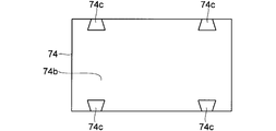
- convex portions are formed only on the outer edge portion of the light incident surface 74a and the light exit surface 74b of the diffuser plate 74 on the light exit surface 74b side.
- the convex portion on the light exit surface 74b side is a diffusion plate fixing portion 74c.
- the diffusion plate fixing portion (convex portion) 74 c of the diffusion plate 74 is exposed through the opening 25 a of the optical sheet 25.
- the arrangement position of the diffusion plate fixing portion (convex portion) 74c of the diffusion plate 74 is preferably the same as that of the first embodiment or its modification.
- the outer edge portion of the diffuser plate 74 (optical sheet 25) is pressed by the frame portion 76a of the frame 76, and the concave insertion portion 76b formed in the frame portion 76a of the frame 76.
- a diffusion plate fixing portion (convex portion) 74c of the diffusion plate 74 is inserted (including press-fitting).
- the diffusion plate fixing portion (convex portion) 74c of the diffusion plate 74 and the insertion portion 76b of the frame 76 are engaged, and the outer edge portion of the diffusion plate 74 is fixed.
- the frame portion 76a of the frame 76 in which the insertion portion 76b is formed corresponds to the “fixing member” of the present invention.
- the planar shape of the diffusion plate fixing portion (convex portion) 74c of the diffusion plate 74 is not particularly limited, and may be any shape.
- the planar shape of the diffusion plate fixing portion (convex portion) 74 c of the diffusion plate 74 may be a square shape, or as shown in FIGS. 15 and 16,
- the planar shape of the diffusion plate fixing portion (convex portion) 74c may be a wedge shape.
- the planar shape of the diffusion plate fixing portion (convex portion) 74c of the diffusion plate 74 may be triangular (including a substantially triangular shape) or may be circular.
- the cross-sectional shape of the diffusion plate fixing portion (convex portion) 74c of the diffusion plate 74 is not particularly limited.
- the diffusion plate fixing portion 74c of the diffusion plate 74 may be movable.
- the present invention is not limited to this and can be applied to display devices other than the liquid crystal display device.
Landscapes
- Physics & Mathematics (AREA)
- Nonlinear Science (AREA)
- Mathematical Physics (AREA)
- Chemical & Material Sciences (AREA)
- Crystallography & Structural Chemistry (AREA)
- General Physics & Mathematics (AREA)
- Optics & Photonics (AREA)
- Planar Illumination Modules (AREA)
- Liquid Crystal (AREA)
Abstract
拡散板の位置ずれを抑制することが可能な照明装置を提供する。この照明装置は、拡散板(24)と、拡散板(24)を固定する固定ピン(27)とを備えている。そして、拡散板(24)の光出射面(24b)側から平面的に見ると、拡散板固定部(24c)が拡散板(24)の光出射面(24b)側の外縁部に設けられた状態となっており、その拡散板固定部(24c)に固定ピン(27)が係合されている。
Description
本発明は、照明装置およびそれを備えた表示装置に関する。
表示装置の一つである液晶表示装置では、映像を表示する液晶表示パネルが非発光であるため、液晶表示パネルの裏面側(液晶表示パネルの表示面側とは反対側)にバックライトユニットと称される照明装置を設置し、そのバックライトユニットで液晶表示パネルの裏面を照明することにより表示動作を行うようになっている。
このような液晶表示装置では、輝度ムラを低減させるために、有効表示領域を均一に照明する必要がある。
したがって、たとえば、直下型のバックライトユニットにおいては、液晶表示パネルの直下領域(液晶表示パネルの裏面と対向する領域)に光源が配置されるが、その光源と液晶表示パネルとの間に拡散板をさらに配置し、光源で生成された光を拡散板で拡散することによって、光源からの光が有効表示領域の全域に行き渡るようにしている(たとえば、特許文献1参照)。
特許文献1のバックライトユニットにおいて、拡散板の固定は、拡散板の外縁部(非表示領域に対応する部分)を筐体で押え付けることによって行っている。しかしながら、この拡散板の固定方法では、拡散板が強固に固定されているとは言えず、拡散板の位置ずれが起こり易い。そして、拡散板が位置ずれを起こすと、拡散板が所望の設置箇所から脱落したり、輝度ムラが発生したりしてしまう。
なお、拡散板の固定方法として、両面テープで拡散板を固定するという方法も考えられる。しかし、低温や高湿の環境下では、両面テープの粘着力が低下する。このため、拡散板を両面テープで固定したとしても、場合によっては拡散板が位置ずれしてしまう。
本発明は、上記課題を解決するためになされたものであり、拡散板の位置ずれを抑制することが可能な照明装置およびそれを備えた表示装置を提供することを目的とする。
上記目的を達成するために、本発明の第1の局面による照明装置は、光入射面および光入射面の反対面である光出射面を有し、光入射面に入射した光を拡散して光出射面から出射する拡散板と、拡散板を固定する固定部材とを備えている。そして、拡散板の光出射面側から平面的に見ると、凹部または凸部からなる拡散板固定部が拡散板の光出射面側の所定部分に設けられた状態となっており、その拡散板固定部に固定部材が係合されている。なお、拡散板固定部が凹部からなっている場合、その凹部は、貫通穴であってもよいし、貫通していなくてもよい。
第1の局面による照明装置では、上記のように構成することによって、拡散板固定部に固定部材が係合しているので、拡散板の意図しない移動や変形が規制される。すなわち、拡散板が強固に固定された状態となり、拡散板の位置ずれが起こり難くなる。そして、このようになっていると、拡散板の所望の設置箇所からの脱落や、輝度ムラの発生などを抑制することができる。
上記第1の局面による照明装置において、拡散板の光出射面上に光学シートが載置される場合には、拡散板固定部を露出させるための開口部が光学シートに形成されていることが好ましい。このように構成すれば、拡散板の光出射面上に光学シートを載置したとしても、その光学シートの開口部から拡散板固定部が露出されるので、拡散板固定部に固定部材を係合させることができる。また、光学シートの固定も行うことができる。
上記第1の局面による照明装置において、拡散板が筐体によって保持されており、その筐体の一部に固定部材が設けられていることが好ましい。このように筐体(拡散板を保持する部材)の一部に固定部材が設けられていれば、拡散板固定部に固定部材を係合させるのが容易となる。
上記第1の局面による照明装置において、拡散板固定部が凹部からなっており、その拡散板固定部に挿入可能なピン状部材が固定部材とされていてもよい。このように構成すれば、拡散板固定部(凹部)に固定部材(ピン状部材)を挿入することにより、容易に、拡散板固定部と固定部材とが係合された状態にすることができる。
拡散板固定部が凹部からなっている構成において、拡散板の光入射面側から平面的に見ると、拡散板の光入射面側の所定部分にも拡散板固定部が設けられた状態となっていることが好ましい。このように構成すれば、拡散板固定部と固定部材との係合面積を増大させることができる。
この場合、拡散板固定部が拡散板の光出射面側から光入射面側に向かって貫通する貫通穴とされていることが好ましい。このように構成すれば、拡散板固定部(貫通穴)に固定部材を完全に貫通させることによって、より強固な拡散板の固定を容易に行うことができる。
また、拡散板固定部が凹部からなっている構成において、固定部材が先細り形状のピン状部材であってもよい。このような固定部材(先細り形状のピン状部材)を拡散板固定部(貫通穴を含む凹部)に挿入すれば、拡散板固定部に楔が打ち込まれたようになるので、拡散板の固定が非常に強固なものとなる。
上記第1の局面による照明装置において、拡散板固定部が凸部からなっており、拡散板固定部を挿入可能な挿入部が固定部材に形成されていてもよい。このように構成すれば、拡散板固定部(凸部)を固定部材の挿入部に挿入することにより、容易に、拡散板固定部と固定部材とが係合された状態にすることができる。
上記第1の局面による照明装置において、拡散板固定部が複数の拡散板固定部を含んでいることが好ましい。このように構成すれば、確実に、拡散板の強固な固定を行うことができる。
拡散板固定部が複数の拡散板固定部を含んでいる構成において、拡散板の平面形状が四角形状とされている場合には、拡散板の光出射面の互いに平行な一対の辺側の外縁部のそれぞれに、拡散板固定部が少なくとも1つずつ配置されていることが好ましい。このように構成すれば、拡散板の強固な固定をバランス良く行うことができる。特に、中央部分が撓み易い大型の拡散板を用いる場合には、拡散板の光出射面の互いに平行な一対の辺側の外縁部のそれぞれに、拡散板固定部が2つ以上ずつ(たとえば、3つずつ)配置されていることがより好ましい。
拡散板の光出射面の互いに平行な一対の辺側の外縁部のそれぞれに拡散板固定部が配置されている構成において、拡散板の光出射面の一方の辺側の外縁部における拡散板固定部の配置位置および他方の辺側の外縁部における拡散板固定部の配置位置が互いにずれていてもよい。このように構成すれば、拡散板固定部の配置位置から、拡散板の表裏の判別を行うことができる。したがって、組み立て作業時に拡散板の表裏が間違われ難くなる。
拡散板固定部が複数の拡散板固定部を含んでいる構成において、複数の拡散板固定部のうちの所定の拡散板固定部の固定部材に対する係合面積が他の拡散板固定部の固定部材に対する係合面積よりも大きくされていてもよい。このように構成すれば、たとえば、拡散板の光出射面の一方の辺側において激しい振動が発生する場合、拡散板の光出射面の一方の辺側の外縁部に所定の拡散板固定部(固定部材に対する係合面積が大きい拡散板固定部)を配置しておくことにより、拡散板の位置ずれを起こり難くすることができる。
上記第1の局面による照明装置において、固定部材または拡散板固定部が移動可能となっており、固定部材または拡散板固定部が拡散板を引っ張る方向に向かって移動されていてもよい。このように構成すれば、拡散板に引っ張り応力がかけられた状態となり、それによって、拡散板の固定がより強固になる。
本発明の第2の局面による表示装置は、上記第1の局面による照明装置と、その照明装置により照明される表示パネルとを備えている。
以上のように、本発明によれば、容易に、拡散板の位置ずれを抑制することが可能となる。
(第1実施形態)
まず、図1~図3を参照して、本発明が適用される表示装置の全体構成の一例について詳しく説明する。
まず、図1~図3を参照して、本発明が適用される表示装置の全体構成の一例について詳しく説明する。
この表示装置は液晶表示装置であって、図1および図2に示すように、液晶表示パネル1と、その液晶表示パネル1の表示面側とは反対の裏面側に設置されたバックライトユニット2とを少なくとも備えており、液晶表示パネル1の表示面が筐体の一つであるベゼル3の開口から露出された構造とされている。そして、液晶表示パネル1の光学的性質(光透過率)が各画素ごとに変化され、かつ、バックライトユニット2からの光で液晶表示パネル1の裏面が照明されることによって、液晶表示パネル1の表示面に所望の映像が表示されるようになっている。なお、液晶表示パネル1は、本発明の「表示パネル」の一例であり、バックライトユニット2は、本発明の「照明装置」の一例である。
具体的な構造としては、液晶表示パネル1は、液晶層(図示せず)、一対の透明基板(アクティブマトリクス基板および対向基板)11および偏光板12などを備えている。液晶層は一対の透明基板11の間に挟持され、その一対の透明基板11の液晶層側とは反対側の面上に偏光板12がそれぞれ配置されている。そして、図1中の破線で囲まれた内側領域は有効表示領域(複数の画素がマトリクス状に配列された領域)とされており、有効表示領域以外の外側領域は非表示領域とされている。
また、バックライトユニット2は、バックシャーシ21、光源モジュール22、反射シート23、拡散板24、光学シート25およびフレーム26などを備えている。なお、バックシャーシ21およびフレーム26は、本発明の「筐体」の一例である。また、光源モジュール22は、本発明の「光源」の一例である。
バックシャーシ21は凹形状とされており、底部と、その底部の外縁に立設された側部とを有している。そして、バックシャーシ21の底部上の側部で取り囲まれた領域、すなわち、凹形状部の内側領域が収容領域とされている。なお、このバックシャーシ21の収容領域の平面形状は四角形状とされている。また、バックシャーシ21の側部の上端付近には平坦部21aが形成されていて、そのバックシャーシ21の平坦部21a上に拡散板24の一部が載置されるようになっている。
光源モジュール22は、複数の放電管22aを含んでいるとともに、バックシャーシ21の収容領域に収容されている。そして、この光源モジュール22によって、液晶表示パネル1を照明するための光が生成される。
反射シート23は、バックシャーシ22の内面(底部の底面および側部の内側面)に沿って配置されている。すなわち、この反射シート23によって、バックシャーシ22の内面が光反射面とされている。これにより、光源モジュール22で生成された光がバックシャーシ22の内面に入射すると、その光は吸収されずに液晶表示パネル1側に向けて反射される。
拡散板24は、平面形状が四角形状の板部材からなっており、バックシャーシ21側に向けられる平面(以下、光入射面24aと言う)と、光入射面24aの反対面であって液晶表示パネル1側に向けられる平面(以下、光出射面24bと言う)とを少なくとも有している。そして、この拡散板24によって、光源モジュール22が液晶表示パネル1側から覆われている。これにより、光源モジュール22で生成された光は、拡散板24の光入射面24aに入射して拡散され、拡散板24の光出射面24bから液晶表示パネル1側に向けて出射される。なお、拡散板24は、その外縁部(非表示領域に対応する部分)がバックシャーシ21の平坦部21a上に載置されることで、光源モジュール22を液晶表示パネル1側から覆った状態で保持されている。
光学シート25は、平面形状が四角形状のシート部材からなっているとともに、拡散シートやレンズシートなどを含んでいる。この光学シート25は拡散板24の光出射面24b上に載置されていて、拡散板24の光出射面24bから出射された光の拡散や集光などを行うようになっている。
フレーム26は、額縁部26aを一体的に有する枠形状とされている。このフレーム26の額縁部26aは拡散板24(光学シート25)の外縁部上に配置され、拡散板24(光学シート25)の外縁部を押え付けている。すなわち、バックシャーシ21の平坦部21aとフレーム26の額縁部26aとの間に拡散板24(光学シート25)の外縁部が挟み込まれていることになる。
そして、フレーム26の額縁部26a上に液晶表示パネル1の外縁部が載置されることによって、液晶表示パネル1の裏面側にバックライトユニット2が設置された状態となっている。なお、液晶表示パネル1は、その外縁部が一対のクッション材4によって挟み込まれている。
ここで、第1実施形態では、図2および図3に示すように、拡散板24の光出射面24b側から平面的に見ると、拡散板24の光出射面24b側の外縁部(バックシャーシ21の平坦部21aとフレーム26の額縁部26aとの間に挟み込まれた部分)に凹部が形成された状態となっている。また、拡散板24の光入射面24a側から平面的に見ると、拡散板24の光入射面24a側の外縁部にも凹部が形成された状態となっている。そして、拡散板24の光出射面24b側の外縁部に形成された凹部および光入射面24a側の外縁部に形成された凹部が板厚方向に互いに連結されることで貫通穴となっている。
言い換えると、第1実施形態では、拡散板24の光出射面24b側の外縁部に、光出射面24b側から光出射面24a側に貫通する貫通穴が形成されている。そして、その拡散板24の貫通穴が拡散板固定部24cとされている。
また、拡散板24の拡散板固定部(貫通穴)24cは、光出射面24b側から平面的に見ると、光出射面24bの各隅部に1つずつ(合計で4つ)配置されている。すなわち、拡散板24の光出射面24bの互いに平行な一対の辺側の外縁部のそれぞれに拡散板固定部(貫通穴)24cが2つずつ配置され、一方の辺側の外縁部における拡散板固定部(貫通穴)24cの配置位置と他方の辺側の外縁部における拡散板固定部(貫通穴)24cの配置位置とが対称となっていることになる。また、拡散板24の複数の拡散板固定部(貫通穴)24cの平面形状としては、全て同じ形状とされている。
さらに、光学シート25には開口部25aが形成されているとともに、その光学シート25の開口部25aが拡散板24の拡散板固定部(貫通穴)24cと重畳する部分に配置されている。このため、拡散板24の光出射面24b上に光学シート25が載置されているが、拡散板24の拡散板固定部(貫通穴)24cは、光学シート25の開口部25aを介して露出されている。
そして、第1実施形態では、拡散板24の拡散板固定部(貫通穴)24cに固定ピン27を挿入(圧入を含む)し、拡散板24の拡散板固定部(貫通穴)24cと固定ピン27とを係合させることによって、拡散板24の外縁部の固定を行なっている。なお、固定ピン27は、本発明の「固定部材」および「ピン状部材」の一例である。
具体的に言うと、固定ピン27は円柱形状に形成された係合部を有しており、拡散板24の拡散板固定部(貫通穴)24cの開口形状は固定ピン27の係合部の形状に対応した形状(円形状)とされている。そして、その拡散板24の円形状に開口された拡散板固定部(貫通穴)24cに、固定ピン27の円柱形状の係合部が挿入されている。
また、拡散板24の拡散板固定部(貫通穴)24cに挿入された固定ピン27は、拡散板24を板厚方向に完全に貫通している。すなわち、固定ピン27の下端部(バックシャーシ21の平坦部21a側の部分)は、拡散板24の拡散板固定部(貫通穴)24cから光入射面24a側に露出され、バックシャーシ21の平坦部21aにまで達している。また、固定ピン27の上端部(フレーム26の額縁部26a側の部分)は、拡散板24の拡散板固定部(貫通穴)24cから光出射面24b側に露出され、さらに、光学シート25の開口部25aを介してフレーム26の額縁部26aにまで達している。
ところで、この固定ピン27は、バックシャーシ21の平坦部21aに後付けされたものであってもよく、バックシャーシ21の平坦部21aに一体化されたものであってもよい。さらに、フレーム26の額縁部26aに固定ピン27が後付けされていてもよいし、フレーム26の額縁部26aに固定ピン27が一体化されていてもよい。
第1実施形態では、上記のように構成することによって、拡散板24の拡散板固定部24cに固定ピン27が係合しているので、拡散板24の意図しない移動や変形が規制される。すなわち、拡散板24が強固に固定された状態となり、拡散板24の位置ずれが起こり難くなる。そして、このようになっていると、拡散板24の所望の設置箇所からの脱落や、輝度ムラの発生などを抑制することができる。
また、第1実施形態では、上記のように、拡散板24の光出射面24b上に載置される光学シート25に開口部25aを形成し、その光学シート25の開口部25aから拡散板24の拡散板固定部24cを露出させることによって、拡散板24の光出射面24b上に光学シート25を載置したとしても、拡散板24の拡散板固定部24cに固定ピン27を係合させることができる。また、光学シート25の固定も行うことができる。
また、第1実施形態では、上記のように、バックシャーシ21の平坦部21aまたはフレーム26の額縁部26aのいずれかに固定ピン27を設けることによって、拡散板24の拡散板固定部24cに固定ピン27を係合させるのが容易となる。
また、第1実施形態では、上記のように、拡散板24の拡散板固定部24cを貫通穴とすることによって、拡散板24の拡散板固定部24cに固定ピン27を挿入することにより、容易に、拡散板24の拡散板固定部24cと固定ピン27とが係合された状態にすることができる。さらに、拡散板24の拡散板固定部24cに固定ピン27を完全に貫通させることによって、拡散板24の拡散板固定部24cと固定ピン27との係合面積が増大するので、より強固な拡散板24の固定を容易に行うことができる。
また、第1実施形態では、上記のように、拡散板24の光出射面24bの互いに平行な一対の辺側の外縁部のそれぞれに拡散板固定部24cを2つずつ配置することによって、拡散板24の強固な固定を、確実に、かつ、バランス良く行うことができる。
なお、第1実施形態の構成において、図4に示すように、拡散板24の光出射面24bの互いに平行な一対の辺側の外縁部のそれぞれに拡散板固定部24cを1つずつ追加し、その追加した拡散板固定部24cを拡散板24の互いに平行な一対の辺側の外縁部の中央付近に配置してもよい。これにより、拡散板24の中央部分における固定が確実となる。したがって、この変形例の構成は、中央部分が撓み易い大型の拡散板24を用いる場合に有効である。
また、第1実施形態の構成において、図5に示すように、拡散板24の光出射面24bの一方の辺側の外縁部における拡散板固定部24cの配置位置および他方の辺側の外縁部における拡散板固定部24cの配置位置を互いにずらしてもよい。これにより、拡散板24の拡散板固定部24cの配置位置から、拡散板24の表裏の判別を行うことができる。したがって、組み立て作業時に拡散板24の表裏が間違われ難くなる。
また、第1実施形態の構成において、図6に示すように、拡散板24の複数の拡散板固定部24cのうちの所定の拡散板固定部24cの開口面積を他の拡散板固定部24cの開口面積よりも大きくし、それに応じて、拡散板24の所定の拡散板固定部24cに挿入される固定ピン27の径をさらに大きくしてもよい。すなわち、拡散板24の所定の拡散板固定部24cの固定ピン27に対する係合面積を他の拡散板固定部24cの固定ピン27に対する係合面積よりも大きくしてもよい。このようにすれば、たとえば、拡散板24の光出射面24bの一方の辺側において激しい振動が発生する場合、拡散板24の光出射面24bの一方の辺側の外縁部に開口面積(係合面積)が大きい所定の拡散板固定部24cを配置しておくことにより、拡散板24の位置ずれを起こり難くすることができる。
また、図示しないが、第1実施形態の構成において、筐体の固定に使用される筐体用の固定ビスを拡散板24の拡散板固定部24cに係合させてもよい。すなわち、本発明の「固定部材」が筐体用の固定ビスであってもよい。
(第2実施形態)
次に、図7を参照して、第2実施形態の構成について詳しく説明する。
次に、図7を参照して、第2実施形態の構成について詳しく説明する。
第2実施形態では、第1実施形態の拡散板24(図2参照)と同様の機能を持つ拡散板34が使用されている一方で、その固定方法が第1実施形態と異なっている。
具体的に言うと、第2実施形態では、拡散板34の光入射面34a側の外縁部には凹部が形成されておらず、拡散板34の光出射面34b側の外縁部にのみ凹部が形成され、その拡散板34の光出射面34b側の凹部が拡散板固定部34cとされている。すなわち、拡散板34の拡散板固定部(凹部)34cは、板厚方向に貫通してはいない。なお、拡散板34の拡散板固定部(凹部)34の配置位置としては、第1実施形態またはその変形例と同じであるのが好ましい。
そして、第2実施形態では、フレーム26の平坦部26aに固定ピン37(本発明の「固定部材」および「ピン状部材」に相当)が設けられており、その固定ピン37が拡散板34の拡散板固定部(凹部)34cに挿入(圧入を含む)されている。これによって、拡散板34の拡散板固定部(凹部)34cと固定ピン37とが係合し、拡散板34の外縁部が固定される。
第2実施形態の他の構成は、第1実施形態と同様であるため、その説明は省略する。
このように構成された第2実施形態では、拡散板34の拡散板固定部34cと固定ピン37との係合面積は第1実施形態よりも減少するが、第1実施形態と略同じ効果が得られる。
また、第2実施形態では、上記のように、拡散板34の光入射面34a側の外縁部には拡散板固定部を形成せず、拡散板34の光出射面34b側の外縁部にのみ拡散板固定部34cを形成することによって、拡散板34の表裏の判別が容易になり、組み立て作業時に拡散板34の表裏が間違われ難くなる。
(第3実施形態)
次に、図8を参照して、第3実施形態の構成について詳しく説明する。
次に、図8を参照して、第3実施形態の構成について詳しく説明する。
第3実施形態では、第1実施形態の拡散板24(図2参照)と同様の機能を持つ拡散板44が使用されている一方で、その固定方法が第1実施形態と異なっている。
具体的に言うと、第3実施形態では、光入射面44a側から光出射面44b側に向かって徐々に狭められた開口幅を持つ貫通穴が拡散板44の外縁部に形成されていて、その拡散板44の外縁部に形成された貫通穴が拡散板固定部44cとされている。なお、拡散板44の拡散板固定部(貫通穴)44cの配置位置としては、第1実施形態またはその変形例と同じであるのが好ましい。
さらに、第3実施形態では、固定ピン47がバックシャーシ21の平坦部21aに設けられており、その固定ピン47は基端部(バックシャーシ21の平坦部21a側の部分)から先端部に向かって先細り形状(略円錐形状)とされている。すなわち、固定ピン47が楔として機能するようになっている。なお、固定ピン47は、本発明の「固定部材」および「ピン状部材」の一例である。
そして、第3実施形態では、固定ピン47が拡散板44の拡散板固定部(貫通穴)44cに挿入(圧入を含む)されているが、固定ピン47が楔形状であるため、実質的に拡散板44の拡散板固定部(貫通穴)44cに楔が打ち込まれたようになっている。これにより、拡散板44の拡散板固定部(貫通穴)44cと固定ピン47とが係合し、拡散板44の外縁部が固定される。
第3実施形態の他の構成は、第1実施形態と同様であるため、その説明は省略する。
このように構成された第3実施形態では、第1実施形態と同様の効果を得ることができる。
また、第3実施形態では、上記のように、固定ピン47を先細り形状とすることによって、拡散板44の拡散板固定部44cに楔が打ち込まれたようになるので、拡散板44の固定が非常に強固なものとなる。
(第4実施形態)
次に、図9を参照して、第4実施形態の構成について詳しく説明する。
次に、図9を参照して、第4実施形態の構成について詳しく説明する。
第4実施形態では、第1実施形態の拡散板24(図2参照)と同様の機能を持つ拡散板54が使用されている一方で、その固定方法が第1実施形態と異なっている。
具体的に言うと、第4実施形態では、拡散板54の光入射面54a側の外縁部および光出射面54b側の外縁部の両方に凹部が形成されているが、拡散板54の光入射面54a側の凹部および光出射面54b側の凹部は板厚方向に互いに連結されておらず、貫通穴とはなっていない。また、拡散板54の光入射面54a側の凹部は、その開口幅が光入射面54aから離れるにしたがって徐々に狭められており、拡散板54の光出射面54b側の凹部は、その開口幅が光出射面54bから離れるにしたがって徐々に狭められている。そして、拡散板54のそれら光入射面54a側の凹部および光出射面54b側の凹部が拡散板固定部54cとされている。なお、拡散板54の拡散板固定部(凹部)54cの配置位置としては、第1実施形態またはその変形例と同じであるのが好ましい。
さらに、第4実施形態では、バックシャーシ21の平坦部21aおよびフレーム26の額縁部26aの両方に固定ピン57が設けられており、これら固定ピン57は楔として機能するようになっている。すなわち、バックシャーシ21の平坦部21aに設けられた固定ピン57は、基端部(バックシャーシ21の平坦部21a側の部分)から先端部に向かって先細り形状(略円錐形状)とされているとともに、フレーム26の額縁部26aに設けられた固定ピン57は、基端部(フレーム26の額縁部26a側の部分)から先端部に向かって先細り形状(略円錐形状)とされている。なお、固定ピン57は、本発明の「固定部材」および「ピン状部材」の一例である。
そして、第4実施形態では、バックシャーシ21の平坦部21aに設けられた固定ピン57が拡散板54の光入射面54a側の拡散板固定部(凹部)54cに挿入(圧入を含む)され、かつ、フレーム26の額縁部26aに設けられた固定ピン57が拡散板54の光出射面54b側の拡散板固定部(凹部)54cに挿入(圧入を含む)されている。言い換えると、拡散板54の光入射面54a側の拡散板固定部(凹部)54cおよび光出射面54b側の拡散板固定部(凹部)54cの両方に楔が打ち込まれたようになっている。これにより、拡散板54の光入射面54a側の拡散板固定部(凹部)54cおよび光出射面54b側の拡散板固定部(凹部)54cの両方に固定ピン57が係合し、拡散板54の外縁部が固定される。
第4実施形態の他の構成は、第1実施形態と同様であるため、その説明は省略する。
このように構成された第4実施形態では、第1実施形態と同様の効果を得ることができる。
また、第4実施形態では、上記のように、固定ピン57を先細り形状とすることによって、第3実施形態と同様、拡散板54の拡散板固定部54cに楔が打ち込まれたようになるので、拡散板54の固定が非常に強固なものとなる。
(第5実施形態)
第5実施形態では、図10に示すような拡散板64が用いられている。具体的には、拡散板64の光入射面64aおよび光出射面64bのうちの少なくとも光出射面64b側の外縁部に拡散板固定部(貫通穴を含む凹部)64cが形成されており、その拡散板固定部64cが光出射面64bの所定の対角線上に位置する一対の隅部に1つずつ配置されている。また、拡散板64の拡散板固定部64cは、光出射面64b側から平面的に見ると、開口幅が広い幅広部と開口幅が狭い幅狭部とを有している。
第5実施形態では、図10に示すような拡散板64が用いられている。具体的には、拡散板64の光入射面64aおよび光出射面64bのうちの少なくとも光出射面64b側の外縁部に拡散板固定部(貫通穴を含む凹部)64cが形成されており、その拡散板固定部64cが光出射面64bの所定の対角線上に位置する一対の隅部に1つずつ配置されている。また、拡散板64の拡散板固定部64cは、光出射面64b側から平面的に見ると、開口幅が広い幅広部と開口幅が狭い幅狭部とを有している。
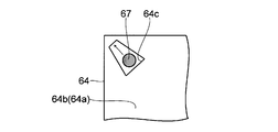
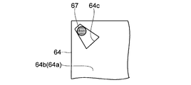
そして、第5実施形態では、固定ピン67(本発明の「固定部材」および「ピン状部材」に相当)がバックシャーシ21の平坦部21a(図2参照)またはフレーム26の額縁部26a(図2参照)に対して移動可能に設けられており、その固定ピン67が拡散板64の拡散板固定部64cの幅狭部に挿入されている。これにより、拡散板64の拡散板固定部64cの幅狭部と固定ピン67とが係合し、拡散板64の外縁部が固定される。
ところで、第5実施形態では、図11および図12に示すように、拡散板64の拡散板固定部64cの幅広部に固定ピン67を挿入した後、その固定ピン67を拡散板固定部64cの幅狭部に移動させることによって、拡散板64の拡散板固定部64cの幅狭部と固定ピン67とを係合させ、さらに、拡散板64に引っ張り応力がかけられた状態にしている。
このように構成された第5実施形態では、第1実施形態と同様の効果を得ることができる。
また、第5実施形態では、上記のように、拡散板64に引っ張り応力がかけられた状態にすることによって、拡散板64の固定がより強固になる。
(第6実施形態)
次に、図13を参照して、第6実施形態の構成について詳しく説明する。
次に、図13を参照して、第6実施形態の構成について詳しく説明する。
第6実施形態では、第1実施形態の拡散板24(図2参照)と同様の機能を持つ拡散板74が使用されている一方で、その固定方法が第1実施形態と異なっている。
具体的に言うと、第6実施形態では、拡散板74の光入射面74aおよび光出射面74bのうちの光出射面74b側の外縁部にのみ凸部が形成されており、その拡散板74の光出射面74b側の凸部が拡散板固定部74cとされている。また、拡散板74の拡散板固定部(凸部)74cは、光学シート25の開口部25aを介して露出されている。なお、拡散板74の拡散板固定部(凸部)74cの配置位置としては、第1実施形態またはその変形例と同じであるのが好ましい。
ここで、第6実施形態では、拡散板74(光学シート25)の外縁部がフレーム76の額縁部76aによって押え付けられており、そのフレーム76の額縁部76aに形成された凹状の挿入部76bに拡散板74の拡散板固定部(凸部)74cが挿入(圧入を含む)されている。これによって、拡散板74の拡散板固定部(凸部)74cとフレーム76の挿入部76bとが係合し、拡散板74の外縁部が固定される。なお、この実施形態では、挿入部76bが形成されているフレーム76の額縁部76aが本発明の「固定部材」に相当する。
ところで、拡散板74の拡散板固定部(凸部)74cの平面形状は特に限定されるものではなく、どのような形状となっていてもよい。たとえば、図14に示すように、拡散板74の拡散板固定部(凸部)74cの平面形状が四角形状となっていてもよいし、図15および図16に示すように、拡散板74の拡散板固定部(凸部)74cの平面形状が楔形状となっていてもよい。また、図示しないが、拡散板74の拡散板固定部(凸部)74cの平面形状が三角形状(略三角形状を含む)となっていてもよいし、円形状となっていてもよい。さらに、拡散板74の拡散板固定部(凸部)74cの断面形状についても特に限定されるものではない。
第6実施形態では、上記のように構成することによって、第1実施形態と同様の効果を得ることができる。
なお、図示しないが、第6実施形態の構成において、拡散板74の拡散板固定部74cを移動可能としてもよい。
今回開示された実施形態は、すべての点で例示であって制限的なものではないと考えられるべきである。本発明の範囲は、上記した実施形態の説明ではなく特許請求の範囲によって示され、さらに、特許請求の範囲と均等の意味および範囲内でのすべての変更が含まれる。
たとえば、上記実施形態では、表示装置としての液晶表示装置に本発明を適用する例について説明したが、本発明はこれに限らず、液晶表示装置以外の表示装置にも適用可能である。
1 液晶表示パネル(表示パネル)
2 バックライトユニット(照明装置)
21 バックシャーシ(筐体)
21a 平坦部
22 光源モジュール(光源)
24、34、44、54、64、74 拡散板
24a、34a、44a、54a、64a、74a 光入射面
24b、34b、44b、54b、64b、74b 光出射面
24c、34c、44c、54c、64c、74c 拡散板固定部
25 光学シート
25a 開口部
26、76 フレーム(筐体)
26a 額縁部
27、37、47、57、67 固定ピン(固定部材)
76a 額縁部(固定部材)
76b 挿入部
2 バックライトユニット(照明装置)
21 バックシャーシ(筐体)
21a 平坦部
22 光源モジュール(光源)
24、34、44、54、64、74 拡散板
24a、34a、44a、54a、64a、74a 光入射面
24b、34b、44b、54b、64b、74b 光出射面
24c、34c、44c、54c、64c、74c 拡散板固定部
25 光学シート
25a 開口部
26、76 フレーム(筐体)
26a 額縁部
27、37、47、57、67 固定ピン(固定部材)
76a 額縁部(固定部材)
76b 挿入部
Claims (15)
- 光入射面および前記光入射面の反対面である光出射面を有し、前記光入射面に入射した光を拡散して前記光出射面から出射する拡散板と、
前記拡散板を固定する固定部材とを備え、
前記拡散板の光出射面側から平面的に見ると、凹部または凸部からなる拡散板固定部が前記拡散板の光出射面側の所定部分に設けられた状態となっており、
前記拡散板固定部に前記固定部材が係合されていることを特徴とする照明装置。 - 前記拡散板の光出射面上に光学シートが載置されており、
前記拡散板固定部を露出させるための開口部が前記光学シートに形成されていることを特徴とする請求項1に記載の照明装置。 - 前記拡散板が筐体によって保持されており、
前記筐体の一部に前記固定部材が設けられていることを特徴とする請求項1または2に記載の照明装置。 - 前記拡散板固定部が凹部からなっており、
前記拡散板固定部に挿入可能なピン状部材が前記固定部材とされていることを特徴とする請求項1~3のいずれかに記載の照明装置。 - 前記拡散板の光入射面側から平面的に見ると、前記拡散板の光入射面側の所定部分にも前記拡散板固定部が設けられた状態となっていることを特徴とする請求項4に記載の照明装置。
- 前記拡散板固定部が前記拡散板の光出射面側から光入射面側に向かって貫通する貫通穴とされていることを特徴とする請求項5に記載の照明装置。
- 前記固定部材が先細り形状のピン状部材であることを特徴とする請求項4~6のいずれかに記載の照明装置。
- 前記拡散板固定部が凸部からなっており、
前記拡散板固定部を挿入可能な挿入部が前記固定部材に形成されていることを特徴とする請求項1~3のいずれかに記載の照明装置。 - 前記拡散板固定部が複数の拡散板固定部を含んでいることを特徴とする請求項1~8のいずれかに記載の照明装置。
- 前記拡散板の平面形状が四角形状とされており、
前記拡散板の光出射面の互いに平行な一対の辺側の外縁部のそれぞれに、前記拡散板固定部が少なくとも1つずつ配置されていることを特徴とする請求項9に記載の照明装置。 - 前記拡散板の光出射面の互いに平行な一対の辺側の外縁部のそれぞれに、前記拡散板固定部が2つ以上ずつ配置されていることを特徴とする請求項10に記載の照明装置。
- 前記拡散板の光出射面の一方の辺側の外縁部における前記拡散板固定部の配置位置および他方の辺側の外縁部における前記拡散板固定部の配置位置が互いにずれていることを特徴とする請求項10または11に記載の照明装置。
- 前記複数の拡散板固定部のうちの所定の拡散板固定部の前記固定部材に対する係合面積が他の拡散板固定部の前記固定部材に対する係合面積よりも大きくされていることを特徴とする請求項9~12のいずれかに記載の照明装置。
- 前記固定部材または前記拡散板固定部が移動可能となっており、
前記固定部材または前記拡散板固定部が前記拡散板を引っ張る方向に向かって移動されていることを特徴とする請求項1~13のいずれかに記載の照明装置。 - 請求項1~14のいずれかに記載の照明装置と、
前記照明装置により照明される表示パネルとを備えていることを特徴とする表示装置。
Priority Applications (1)
| Application Number | Priority Date | Filing Date | Title |
|---|---|---|---|
| US13/695,490 US8876318B2 (en) | 2010-05-19 | 2011-01-13 | Illumination device and display device incorporating same |
Applications Claiming Priority (2)
| Application Number | Priority Date | Filing Date | Title |
|---|---|---|---|
| JP2010-115205 | 2010-05-19 | ||
| JP2010115205 | 2010-05-19 |
Publications (1)
| Publication Number | Publication Date |
|---|---|
| WO2011145355A1 true WO2011145355A1 (ja) | 2011-11-24 |
Family
ID=44991473
Family Applications (1)
| Application Number | Title | Priority Date | Filing Date |
|---|---|---|---|
| PCT/JP2011/050414 Ceased WO2011145355A1 (ja) | 2010-05-19 | 2011-01-13 | 照明装置およびそれを備えた表示装置 |
Country Status (2)
| Country | Link |
|---|---|
| US (1) | US8876318B2 (ja) |
| WO (1) | WO2011145355A1 (ja) |
Cited By (1)
| Publication number | Priority date | Publication date | Assignee | Title |
|---|---|---|---|---|
| JP6043874B2 (ja) * | 2013-08-22 | 2016-12-14 | 堺ディスプレイプロダクト株式会社 | 照明装置及び表示装置 |
Families Citing this family (1)
| Publication number | Priority date | Publication date | Assignee | Title |
|---|---|---|---|---|
| KR102395088B1 (ko) * | 2015-11-26 | 2022-05-04 | 엘지디스플레이 주식회사 | 백라이트 유닛 및 이를 포함하는 액정 표시 장치 |
Citations (4)
| Publication number | Priority date | Publication date | Assignee | Title |
|---|---|---|---|---|
| JP2000340017A (ja) * | 1999-05-25 | 2000-12-08 | West Electric Co Ltd | 照明装置 |
| JP2004086046A (ja) * | 2002-08-28 | 2004-03-18 | Sharp Corp | 照明装置及び液晶バックライト装置 |
| JP2008305713A (ja) * | 2007-06-08 | 2008-12-18 | Fujifilm Corp | 面状照明装置 |
| JP2009210763A (ja) * | 2008-03-04 | 2009-09-17 | Epson Imaging Devices Corp | 電気光学装置および電子機器 |
Family Cites Families (2)
| Publication number | Priority date | Publication date | Assignee | Title |
|---|---|---|---|---|
| JP4394497B2 (ja) | 2004-03-30 | 2010-01-06 | Nec液晶テクノロジー株式会社 | 照明装置 |
| JP4909866B2 (ja) * | 2007-10-10 | 2012-04-04 | 富士フイルム株式会社 | 面状照明装置 |
-
2011
- 2011-01-13 US US13/695,490 patent/US8876318B2/en not_active Expired - Fee Related
- 2011-01-13 WO PCT/JP2011/050414 patent/WO2011145355A1/ja not_active Ceased
Patent Citations (4)
| Publication number | Priority date | Publication date | Assignee | Title |
|---|---|---|---|---|
| JP2000340017A (ja) * | 1999-05-25 | 2000-12-08 | West Electric Co Ltd | 照明装置 |
| JP2004086046A (ja) * | 2002-08-28 | 2004-03-18 | Sharp Corp | 照明装置及び液晶バックライト装置 |
| JP2008305713A (ja) * | 2007-06-08 | 2008-12-18 | Fujifilm Corp | 面状照明装置 |
| JP2009210763A (ja) * | 2008-03-04 | 2009-09-17 | Epson Imaging Devices Corp | 電気光学装置および電子機器 |
Cited By (2)
| Publication number | Priority date | Publication date | Assignee | Title |
|---|---|---|---|---|
| JP6043874B2 (ja) * | 2013-08-22 | 2016-12-14 | 堺ディスプレイプロダクト株式会社 | 照明装置及び表示装置 |
| US9739931B2 (en) | 2013-08-22 | 2017-08-22 | Sakai Display Products Corporation | Lighting device and display apparatus |
Also Published As
| Publication number | Publication date |
|---|---|
| US20130050991A1 (en) | 2013-02-28 |
| US8876318B2 (en) | 2014-11-04 |
Similar Documents
| Publication | Publication Date | Title |
|---|---|---|
| JP5184701B2 (ja) | 照明装置、表示装置、及びテレビ受信装置 | |
| JP5303657B2 (ja) | 照明装置、表示装置、及びテレビ受信装置 | |
| JP6695035B2 (ja) | バックライト装置および液晶表示装置 | |
| JP5848631B2 (ja) | 照明装置およびそれを備えた表示装置 | |
| JP2012004067A (ja) | 面照明装置 | |
| CN102472441A (zh) | 照明装置、显示装置以及电视接收装置 | |
| CN102803824A (zh) | 照明装置、显示装置以及电视接收装置 | |
| CN102459993A (zh) | 照明装置、显示装置以及电视接收装置 | |
| WO2011093119A1 (ja) | 照明装置、表示装置、テレビ受信装置 | |
| WO2012002074A1 (ja) | 照明装置、表示装置及びテレビ受信装置 | |
| WO2009107433A1 (ja) | 照明装置、表示装置、及びテレビ受信装置 | |
| WO2010146917A1 (ja) | 照明装置、表示装置、及びテレビ受信装置 | |
| WO2014017389A1 (ja) | 表示装置、及びテレビ受信装置 | |
| JP4607225B2 (ja) | 光源モジュール、液晶表示装置および照明装置 | |
| WO2011111444A1 (ja) | 照明装置、表示装置、及びテレビ受信装置 | |
| WO2013191051A1 (ja) | 表示装置、及びテレビ受信装置 | |
| KR20060016117A (ko) | 면광원 장치 | |
| JP2018181630A (ja) | バックライト | |
| JP6043874B2 (ja) | 照明装置及び表示装置 | |
| JP2014022060A (ja) | バックライト装置、表示装置、及びテレビ受信装置 | |
| WO2011145355A1 (ja) | 照明装置およびそれを備えた表示装置 | |
| WO2013080882A1 (ja) | 照明装置、表示装置及びテレビ受信装置 | |
| WO2013011940A1 (ja) | 照明装置、表示装置、及びテレビ受信装置 | |
| WO2008068935A1 (ja) | 光源ユニット及び表示装置 | |
| JP2009205827A (ja) | バックライト装置 |
Legal Events
| Date | Code | Title | Description |
|---|---|---|---|
| 121 | Ep: the epo has been informed by wipo that ep was designated in this application |
Ref document number: 11783292 Country of ref document: EP Kind code of ref document: A1 |
|
| WWE | Wipo information: entry into national phase |
Ref document number: 13695490 Country of ref document: US |
|
| NENP | Non-entry into the national phase |
Ref country code: DE |
|
| 122 | Ep: pct application non-entry in european phase |
Ref document number: 11783292 Country of ref document: EP Kind code of ref document: A1 |
|
| NENP | Non-entry into the national phase |
Ref country code: JP |