WO2011145236A1 - 動線作成装置及び動線作成方法 - Google Patents
動線作成装置及び動線作成方法 Download PDFInfo
- Publication number
- WO2011145236A1 WO2011145236A1 PCT/JP2011/000030 JP2011000030W WO2011145236A1 WO 2011145236 A1 WO2011145236 A1 WO 2011145236A1 JP 2011000030 W JP2011000030 W JP 2011000030W WO 2011145236 A1 WO2011145236 A1 WO 2011145236A1
- Authority
- WO
- WIPO (PCT)
- Prior art keywords
- state
- reference point
- flow line
- tracking target
- rectangular frame
- Prior art date
Links
Images


Classifications
-
- G—PHYSICS
- G06—COMPUTING; CALCULATING OR COUNTING
- G06T—IMAGE DATA PROCESSING OR GENERATION, IN GENERAL
- G06T7/00—Image analysis
- G06T7/20—Analysis of motion
-
- G—PHYSICS
- G06—COMPUTING; CALCULATING OR COUNTING
- G06V—IMAGE OR VIDEO RECOGNITION OR UNDERSTANDING
- G06V20/00—Scenes; Scene-specific elements
- G06V20/50—Context or environment of the image
- G06V20/56—Context or environment of the image exterior to a vehicle by using sensors mounted on the vehicle
- G06V20/58—Recognition of moving objects or obstacles, e.g. vehicles or pedestrians; Recognition of traffic objects, e.g. traffic signs, traffic lights or roads
-
- G—PHYSICS
- G06—COMPUTING; CALCULATING OR COUNTING
- G06V—IMAGE OR VIDEO RECOGNITION OR UNDERSTANDING
- G06V20/00—Scenes; Scene-specific elements
- G06V20/50—Context or environment of the image
- G06V20/56—Context or environment of the image exterior to a vehicle by using sensors mounted on the vehicle
- G06V20/588—Recognition of the road, e.g. of lane markings; Recognition of the vehicle driving pattern in relation to the road
-
- G—PHYSICS
- G06—COMPUTING; CALCULATING OR COUNTING
- G06T—IMAGE DATA PROCESSING OR GENERATION, IN GENERAL
- G06T2207/00—Indexing scheme for image analysis or image enhancement
- G06T2207/30—Subject of image; Context of image processing
- G06T2207/30196—Human being; Person
-
- G—PHYSICS
- G06—COMPUTING; CALCULATING OR COUNTING
- G06T—IMAGE DATA PROCESSING OR GENERATION, IN GENERAL
- G06T2207/00—Indexing scheme for image analysis or image enhancement
- G06T2207/30—Subject of image; Context of image processing
- G06T2207/30241—Trajectory
Definitions
- the present invention relates to a flow line creation apparatus and a flow line creation method for detecting a tracking target in an image and generating a flow line representing a movement locus of the tracking target.
- a flow line creation device that creates a flow line representing a movement trajectory to be tracked has been used.
- the flow line creation device captures a target space with a camera installed at a relatively high location, recognizes a tracking target (for example, a person) from the captured image, performs tracking, and creates a flow line.
- the flow line is for tracking the location in the target space of the tracking target shown in the image. Accordingly, the movement of the tracking target in the vertical direction (y direction) in the image space represents the movement of the tracking target in the near direction or the depth direction with reference to the camera in the target space. Further, the movement of the tracking target in the horizontal direction (x direction) in the image space represents the movement of the tracking target in the left-right direction with reference to the camera in the target space.
- a tracking target in an image is recognized, a rectangular frame including the tracking target is created, and the center point of the frame is set at a fixed time interval.
- a flow line is created by tying them together (see, for example, Patent Document 1).
- the center point of the frame may move in the image space even though the position of the person in the target space has not moved. For this reason, if the flow line is created by always tracking the center point of the frame, the movement of the center point, which is unnecessary for tracking the position of the person in the target space, is generated as the flow line, and the actual target is generated. A flow line that accurately represents the movement of a person in space may not be created.
- a flow line is created by reflecting such movement of the center point, a flow line indicating that the person has moved in the front direction with respect to the camera in the target space is created.
- a flow line that accurately represents the movement of the person in the actual target space may not be created.
- the above problem can be solved by creating a flow line after recognizing the movement of a person such as “squatting” or “stretching their hands” using image recognition technology. Processing burden increases.
- the present invention has been made to solve the conventional problems, and can reduce the creation of an erroneous flow line that does not increase the processing load and creates a flow line that does not accurately reflect the movement of the tracking target.
- An object is to provide a line creation device and a flow line creation method.
- the flow line creation device of the present invention is a flow line creation device that creates a flow line that represents a movement trajectory of a tracking target, detects the tracking target from an image frame, and detects detection result information including a detection area of the tracking target.
- the object detection unit to be generated, the state determination unit that determines the state of the tracking target based on the detection result information, and the reference of the tracking target using the detection region in a method corresponding to the state determined by the state determination unit It has a configuration comprising a reference point creation unit that creates points and a flow line creation unit that generates a flow line that represents a movement trajectory of a tracking target by connecting a plurality of reference points created for a plurality of image frames. ing.
- Another aspect of the present invention is a flow line creation method for creating a flow line representing a movement trajectory of a tracking target, which detects the tracking target from an image frame and generates detection result information including a detection area of the tracking target.
- the present invention can reduce the creation of an erroneous flow line that creates a flow line that does not accurately reflect the movement of the tracking target without increasing the processing load.
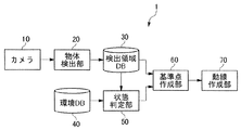
- FIG. 1 is a block diagram of a flow line creation device according to an embodiment of the present invention.
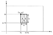
- FIG. 2 is a diagram showing a rectangular frame in the embodiment of the present invention.
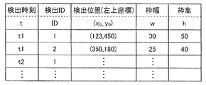
- FIG. 3 is a diagram showing an example of detection result information in the embodiment of the present invention.
- FIG. 4 is a diagram showing an example of environment information in the embodiment of the present invention.
- FIG. 5 is a diagram showing an example of environment information stored in the environment database according to the embodiment of the present invention.
- FIG. 6 is a diagram for explaining the determination condition for the transition from the “normal” state to the “squatting” state and the creation of the reference point in the “squatting” state according to the embodiment of the present invention.
- FIG. 1 is a block diagram of a flow line creation device according to an embodiment of the present invention.
- FIG. 2 is a diagram showing a rectangular frame in the embodiment of the present invention.
- FIG. 3 is a diagram showing an example of detection result information in the embodiment of the present invention.
- FIG. 4
- FIG. 7 is a diagram for explaining the determination condition for the transition from the “normal” state to the “hand-stretched” state and the creation of the reference point in the “hand-stretched” state in the embodiment of the present invention.
- FIG. 8 is a diagram for explaining the determination condition for the transition from the “normal” state to the “floor reflection” state and the creation of the reference point in the “floor reflection” state in the embodiment of the present invention.
- FIG. 9 is a diagram illustrating determination conditions for transition from the “normal” state to the “shielded” state and the creation of reference points in the “shielded” state in the embodiment of the present invention.
- FIG. 10 is a diagram for explaining the creation of a reference point in the “noise” state in the embodiment of the present invention.
- FIG. 11 is a flowchart showing the operation of the state determination unit in the embodiment of the present invention.
- FIG. 12 is a flowchart of processing in the “squatting” state in the embodiment of the present invention.
- FIG. 13 is a flowchart of processing in the “hand stretched” state according to the embodiment of the present invention.
- FIG. 14 is a flowchart of processing in the “floor reflection” state according to the embodiment of the present invention.
- FIG. 15 is a flowchart of processing in the “shielded” state according to the embodiment of the present invention.
- FIG. 16 is a flowchart of processing in the “noise” state according to the embodiment of the present invention.
- a flow line creation apparatus is a flow line creation apparatus that creates a flow line representing a movement trajectory of a tracking target, and includes a detection area of the tracking target by detecting the tracking target from an image frame.
- An object detection unit that generates detection result information, a state determination unit that determines the state of the tracking target based on the detection result information, and a detection region in a method corresponding to the state determined by the state determination unit,
- a reference point creation unit that creates a reference point to be tracked and a flow line creation unit that connects a plurality of reference points created for a plurality of image frames to generate a flow line that represents a movement trajectory of the track target. It has a configuration.
- This configuration creates a reference point for the tracking target in a manner corresponding to the state of the tracking target, thereby reducing the generation of an erroneous flow line that creates a flow line that does not accurately reflect the movement of the tracking target. Further, since the state of the tracking target is determined based on the detection result information including the detection area, the processing load can be suppressed as compared with the case where the operation of the tracking target is recognized.
- the state determination unit determines the state of the tracking target based on the change in the detection area.
- This configuration makes it possible to determine whether the detection area has changed with the movement of the tracking target or whether the detection area has changed with a change in the state of the tracking target based on the change of the detection area.
- the state determination unit determines the state of the tracking target based on the positional relationship between the environmental information set in the flow line creation target space and the detection area.
- This configuration makes it possible to determine whether the detection area has changed due to the movement of the tracking target or whether the detection area has changed by being at the position where the environmental information is set.
- the reference point creation unit determines that the state determination unit is in a specific state that is not a normal state
- the reference point creation unit uses the current and past detection areas to determine the reference point. create.
- This configuration allows a part of the past detection area to be substituted when there is a part of the detection area that is used to create the reference point that is not suitable for using the current detection area.
- the object detection unit includes an upper line, an underline, a right line, and a left line as a detection area, and generates a rectangular frame that includes the detected tracking target.
- the state determination unit compares the current rectangular frame with the past rectangular frame, and the movement of the underline is smaller than the first threshold and the movement of the upper line in the downward direction is the first.
- the threshold value of 2 it is determined that it is in a squatting state, and when it is determined that the state determining unit is in a squatting state, the upper line of the past rectangular frame is used as the upper line of the rectangular frame.
- the reference point does not change due to the change of the detection area, and the movement that does not accurately reflect the movement of the tracking target. It is possible to prevent creation of an erroneous flow line such as creating a line.
- the state determination unit compares the current rectangular frame with the past rectangular frame, and the movement of the upper line and the lower line is smaller than the third threshold value, and the right line moves in the right direction.
- the movement or movement of the left line in the left direction is larger than the fourth threshold value, it is determined that the hand is stretched, and the reference point creation unit is determined to be stretched by the state determination unit Adopts the right line or left line of the past rectangular frame as the right line or left line of the rectangular frame to create a reference point.
- the state determination unit includes at least one of the underline end points of the rectangular frame of the current detection result information included in the floor reflection region set in the flow line creation target space. Is determined to be in the floor reflection state, and when the state determination unit determines that it is in the floor reflection state, the reference point creation unit displays the rectangular frame of the past detection result information as an underline of the rectangular frame. Adopt an underline to create a reference point.
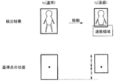
- the state determination unit is in a shielded state when the underline of the rectangular frame of the current detection result information is included in the shield area set in the flow line creation target space.
- the reference point creation unit adopts the underline of the rectangular frame of the past detection result information as the underline of the rectangular frame, Create
- the state determination unit does not correspond to a specific state other than the normal state, but the aspect ratio or size of the rectangular frame of the detection result information has changed beyond the fifth threshold.
- the reference point creation unit determines that it is in a noise state in the state determination unit, it averages a plurality of rectangular frames in the period determined to be in the noise state To create a reference point.
- Another aspect of the present invention is a flow line creation method for creating a flow line representing a movement trajectory of a tracking target, which detects the tracking target from an image frame and generates detection result information including a detection area of the tracking target.
- the reference point of the tracking target is created by a method corresponding to the state of the tracking target, similarly to the above-described flow generating device, so that a flow line that does not accurately reflect the movement of the tracking target is created.
- the creation of erroneous flow lines can be reduced. Further, since the state of the tracking target is determined based on the detection result information including the detection area, the processing load can be suppressed as compared with the case where the operation of the tracking target is recognized.
- FIG. 1 shows a flow line creation device according to a first embodiment of the present invention.
- a flow line creation device 1 according to an embodiment of the present invention includes a camera 10, an object detection unit 20, a detection region database 30, an environment database 40, a state determination unit 50, and a reference point creation unit 60. And a flow line creation unit 70.
- the camera 10 includes modules necessary for photographing a subject such as a lens and an image sensor.
- the camera 10 is installed at a relatively high location in the target space in order to photograph a space for which a flow line is to be created (hereinafter referred to as “target space”).
- the camera 10 captures the target space, generates image data, and outputs the generated image data to the object detection unit 20.
- the object detection unit 20 detects a tracking target from the image data generated by the camera 10 and outputs detection result information including a detection area indicating the tracking target area to the detection area database 30.
- the object detection unit 20 employs a method using background difference as a detection method. Specifically, the object detection unit 20 sets an image in a state where no person to be tracked exists as a reference image, compares the reference image with the current image, and sets a set of pixels having a difference as a tracking target. Recognize as a human area. Then, the object detection unit 20 generates a rectangular frame including the recognized person area as the detection area.
- the y coordinate of the upper line of the rectangular frame is called the upper coordinate
- the y coordinate of the lower line is called the lower coordinate
- the x coordinate of the right line is called the right coordinate
- the x coordinate of the left line is called the left coordinate
- Object detection unit 20 among the coordinates of a pixel in the difference compared with the reference image, the coordinates obtained by adding a maximum predetermined margin to the y coordinate of the upper-coordinate y o, minus a predetermined margin to the minimum y-coordinate coordinates were the lower coordinate y u, the coordinate obtained by adding a predetermined margin to the rightmost x coordinate and right coordinates x r, the coordinates obtained by subtracting a predetermined margin to the leftmost x coordinate and left coordinates x l.
- FIG. 2 is a diagram showing a rectangular frame in the present embodiment.
- the detection position (upper left coordinates) is (x 0 , y 0 )
- the frame width is w
- the frame height is h
- the upper coordinate yo is y 0 (y coordinate of the detection position) as shown in FIG.
- the lower coordinate yu is y 0 -h (the y coordinate of the detection position ⁇ the frame height)
- the right coordinate x r is x 0 + w (the x coordinate of the detection position + the frame width)
- the left coordinate x 1 is x 0 (the detection position) X coordinate).
- the object detection unit 20 When the object detection unit 20 recognizes the person's area, the object detection unit 20 outputs the time, the tracking ID, the upper left coordinates of the set frame, the frame width, and the frame height to the detection area database 30 as detection result information.
- the detection area database 30 stores detection result information output by the object detection unit 20.
- FIG. 3 is a diagram showing an example of detection result information stored in the detection area database 30.
- the detection area database 30 stores detection time information, detection ID, detection position, frame width, and frame height information as detection result information.
- the detection time is the time when the tracking target is detected.
- the detection ID is a tracking ID that is uniquely given to the tracking target. The same detection ID is assigned to the tracking target determined to be the same.
- the detection position is the upper left coordinates of the rectangular frame surrounding the tracking target, and the frame width and the frame height are the rectangular frame width and height surrounding the tracking target.
- the environment database 40 holds information representing the shooting environment of the camera 10 (hereinafter referred to as “environment information”).
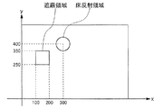
- the imaging environment includes information on the floor reflection area and information on the shielding area.
- the floor reflection area and the shielding area are areas in the image space generated by the camera 10.
- the floor reflection region is a region where the tracking target is easily reflected on the floor.
- the shielding area is an area where the tracking target is shielded from the camera 10.
- the environmental information is stored in advance in the environmental database 40 based on the installation state (position, angle, angle of view, etc.) of the camera 10.
- FIG. 4 is a diagram illustrating an example of environment information
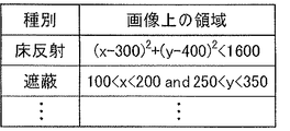
- FIG. 5 is a diagram illustrating an example of environment information stored in the environment database 40.
- the environment database 40 stores information on the type of environment information and information on the area on the image.
- the state determination unit 50 determines the state of the tracking target based on the current detection result information, the past detection result information, and the environment information stored in the environment database 40, and generates state type information. Then, the state type information is output to the reference point creation unit 60 together with the time and tracking ID at that time.
- Status type information is information indicating the current status of the tracking target. There are six types of states: “normal”, “squatting”, “hand stretching”, “floor reflection”, “shielding”, and “noise”. As for the “hand stretched” state, there are a “right hand stretched” state and a “left hand stretched” state.
- the state type information is used to create a reference point by the reference point creation unit 60.
- the state determination unit 50 determines whether or not the state has changed from the “normal” state to any one of “squatting”, “hand stretching”, “floor reflection”, “shielding”, and “noise”, and “squatting”. ”,“ Hand stretched ”,“ floor reflection ”,“ shielding ”, and“ noise ”are determined to return to the“ normal ”state. A method of state determination in the state determination unit 50 will be described later.
- the reference point creation unit 60 reads the necessary current and past detection result information from the search information database 3 based on the state type information input from the state determination unit 50, creates a reference point, and moves its coordinates. The data is output to the line creation unit 70. A method of creating a reference point in the reference point creating unit 60 will be described later.
- the flow line creation unit 70 creates a flow line by connecting the reference points created by the reference point creation unit 60 in time order. When connecting the reference points, they may be connected with a smooth curve instead of a straight line.
- the lower coordinate at time t is y ut
- the upper coordinate is y ot
- the right coordinate is x rt
- the left coordinate is x lt .
- the state determination unit 50 and the reference point creation unit 60 determine the state using these lower coordinate y ut , upper coordinate y ot , right coordinate x rt , and left coordinate x lt to obtain a reference point.
- the upper coordinate y ot and the left coordinate x lt are stored in the detection area database 30 and are used as they are.
- the reference point creation unit 60 uses the information of the upper coordinate y ot1 , the left coordinate x lt1 , the frame width w t1 , and the frame height h t1 stored in the detection area database 30 to use the following formulas (3 ′) and (4 ') To obtain the reference point.
- x x lt1 + w t1 / 2 (3 ′)
- y y ot1 -h t1 / 2 (4 ')
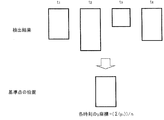
- FIG. 6 is a diagram for explaining the determination condition for the transition from the “normal” state to the “squat” state and the creation of a reference point for the “squat” state.
- FIG. 6 shows a state in which the tracking target that was in the “normal” state at time t 1 is in the “squatting” state at time t 2 .
- the position of the foot does not change and the position of the head is lowered.
- the position of the underline of the rectangular frame is not substantially changed, and only the position of the overline is greatly lowered.
- the state determination unit 50 determines that the squatting has occurred when the underline difference is within a predetermined range and the overline has decreased by a predetermined amount or more. Specifically, when the tracking target of a certain tracking ID is in the “normal” state at time t 1 , the tracking target of the same tracking ID at time t 2 satisfies the determination condition of the “squatting” state described below. If meet, tracked the tracking ID determines at time t 2 and the transition to the state of "squatting".
- Condition 1 is a condition that ⁇ 1 is an error range, and the difference between the lower coordinates of the rectangular frame is within the error range.
- Condition 2 is a condition that the upper coordinate of the rectangular frame becomes smaller than the threshold value a. Note that, when this condition is continuously satisfied for a certain time or more, it may be determined that the tracking target is in the “squatting” state.
- the state determination unit 50 determines that the state is “squatting” using the determination condition of the “squatting” state
- the state type information indicating the “squatting” state is set to the time when the state “squatting” (time t 2 ). And the tracking ID together with the tracking ID.
- the reference point creation unit 60 acquires the state type information indicating the “squatting” state, the state detection information at the time (time t 2 ) at which the “squatting” state is reached and the “normal” state from the detection region database 30.
- the state detection information at the last time (time t 1 ) is read, and the x coordinate and y coordinate of the reference point in the “squatting” state at time t 2 are obtained by the following equations (5) and (6).
- Condition 3 is a condition in which the lower coordinate of the rectangular frame is changed to be equal to or greater than the threshold value, where b is the threshold value.
- b is the threshold value.
- Condition 4 is that the error range is ⁇ 2 , and the upper coordinate of the rectangular frame is approximately the same as the upper coordinate at time t 1 in the “normal” state immediately before the “squatting” state. This means that the person who was crouched stood up, and in this case, the state type is returned from the “squatting” state to the “normal” state.
- the reference point creation unit 60 sets the center point of the rectangular frame as the reference point according to the above formulas (3 ′) and (4 ′).
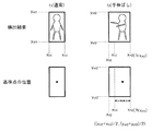
- FIG. 7 is a diagram for explaining determination conditions for transition from the “normal” state to the “hand stretched” state and creation of a reference point for the “hand stretched” state. is there.
- FIG. 7 shows a state in which the tracking target that was in the “normal” state at time t 1 is in the “hand stretched” state at time t 2 .
- the positions of the head and legs do not change, and the hand extends to the left or right.
- the positions of the upper line and the underline are not substantially changed, and the frame width is increased.
- the state determination unit 50 allows the person to be tracked to reach out when the difference between the overline and the underline is within a predetermined range and the frame width increases to a predetermined threshold value or more.
- the tracking target of a certain tracking ID is in the “normal” state at time t 1
- the following tracking condition for the tracking target of the same tracking ID at time t 2 is the “hand stretched” state: If satisfying, it tracked the tracking ID determines at time t 2 and the transition to the state of the "hands stretched”.
- Condition 5 is a condition in which ⁇ 3 is an error range, and the difference between the lower coordinates of the rectangular frame is within the error range.
- Condition 6 is a condition that ⁇ 4 is an error range, and the difference between the upper coordinates of the rectangular frame is within the error range.
- Condition 7 is a condition that the frame width of the rectangular frame increases by a threshold value c or more. Note that, when this condition is continuously satisfied for a certain time or more, it may be determined that the tracking target is in the “hand stretched” state.
- the state determination unit 50 further compares
- the state determination unit 50 determines that the tracking target is in the “hand-stretched” state using the determination condition in the “hand-stretched” state, whether the state is a “right-handed” state according to the above-described determination condition. , It is determined whether the state is the “left hand stretched” state, and the state type information indicating the “right hand stretched” state or the state type information indicating the “left hand stretched” state is set to the “hand stretched” state (time t 2 ). And the tracking ID together with the tracking ID.
- the reference point creation unit 60 acquires the state type information indicating the “right-handed” state, the state detection information at the time (time t 2 ) when the “right-handed” state is obtained, and “normal” from the detection region database 30.
- the state detection information at the last time that was in the state (time t 1 ) is read, and the x and y coordinates of the reference point in the “right-handed” state at time t 2 are obtained by the following equations (7) and (8). .
- the x coordinate of the reference point at time t 2 in the “right-handed” state is obtained using the left coordinate x lt1 at the last time (time t 1 ) in the “normal” state. Is. That is, even in the “right hand stretched” state, as in the “normal” state, the center point of the rectangular frame is used as a reference point, but the left coordinate of this rectangular frame is the time when the “right hand stretched” state is reached. Instead of the left coordinate, the left coordinate at the time of the last “normal” state is adopted.
- the reference point creation unit 60 acquires the state type information indicating the “left hand stretched” state, the state detection information at the time when the “left hand stretched” state is reached (time t 2 ), and “normal”.
- the state detection information at the last time in the state (time t 1 ) is read, and the x coordinate and y coordinate of the reference point in the “left hand stretched” state at time t 2 are obtained by the following equations (9) and (10). .
- the x coordinate of the reference point at the time t 2 in the “left-handed” state is obtained using the right coordinate x rt1 at the last time (time t 1 ) in the “normal” state.
- the center point of the rectangular frame is used as a reference point, but the time when the “left hand stretched” state is entered as the right coordinate of this rectangular frame.
- the right coordinate at the time of the last “normal” state is adopted.
- the state determination unit 50 determines whether the tracking target with the same tracking ID is in the “hand-stretched” state when the tracking target with a tracking ID at time t 2 or satisfies the condition 8 below at time t 3, or if it meets both conditions 9 and conditions 10 determines the "hands stretched” state at that time t 3 and returned to the "normal” state.
- Condition 8
- Condition 9
- Condition 10
- Condition 8 is a condition that the threshold height is d, and the frame height of the rectangular frame is changed to the threshold value or more. That is, if the frame height has changed significantly, there is a possibility that the person to be tracked is moving in the direction approaching the camera 10, and it is determined that the increase in the frame width in this case is the “hand stretched” state. It is not appropriate to do. Therefore, in such a case, the “hand stretched” state is canceled and the state type is returned to the “normal” state.
- Condition 9 is a condition in which the error range is ⁇ 5 and the frame height of the rectangular frame is not substantially changed.
- the condition 10 is a condition that the error range is ⁇ 6 and the frame width of the rectangular frame is not substantially changed.
- FIG. 8 is a diagram for explaining the determination condition for the transition from the “normal” state to the “floor reflection” state and the creation of the reference point of the “floor reflection” state. is there.
- FIG. 8 shows a state in which the tracking target that was in the “normal” state at time t 1 is in the “floor reflection” state at time t 2 .
- the object detection unit 20 detects the tracking target using the difference between the past image and the current image. Therefore, when the person is in an area where the person easily reflects, the portion of the floor that reflects the person Becomes a difference area, and the rectangular frame is set larger than the actual person.
- the state determination unit 50 determines that the state is the “floor reflection” state when at least one of the end points of the underline is in the floor reflection region.
- the state determination unit 50 refers to the environment information stored in the environment database 40 in order to determine the “floor reflection” state. Specifically, if, in the environment database 40, when the environmental information as shown in FIG. 5 is stored, the tracking target at time t 2 is when the determination condition is satisfied the "floor reflection" state below , the tracking target, it is determined that the "floor reflection” state at time t 2.
- the determination condition for the “floor reflection” state is that at least one of the following conditions 11 and 12 is true.
- Condition 11 (x rt2 ⁇ 300) 2 + (y ut2 ⁇ 400) 2 ⁇ 1600
- Condition 12 (x lt2 ⁇ 300) 2 + (y ut2 ⁇ 400) 2 ⁇ 1600
- Condition 11 is a condition that the right end point of the underline is in the floor reflection region.
- the condition 12 is a condition that the left end point of the underline is in the floor reflection area.
- the state determination unit 50 determines that the state is the “floor reflection” state using the determination condition of the “floor reflection” state, the state type information indicating the “floor reflection” state is changed to the “floor reflection” state.
- the time (time t 2 ) and the tracking ID are output to the reference point creation unit 60.
- the reference point creation unit 60 acquires the state type information indicating the “floor reflection” state, the state detection information at the time (time t 2 ) when the “floor reflection” state is entered, and “normal” from the detection region database 30.
- the state detection information at the last time in the state (time t 1 ) is read, and the x and y coordinates of the reference point in the “floor reflection” state at time t 2 are obtained by the following equations (11) and (12). .
- the y coordinate of the reference point at the time t 2 in the “floor reflection” state is obtained using the lower coordinate ut1 of the last time (time t 1 ) in the “normal” state. Is. That is, in the “floor reflection” state, as in the “normal” state, the center point of the rectangular frame is used as a reference point. Instead of the lower coordinate, the lower coordinate of the time when the “normal” state was last is adopted.
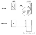
- FIG. 9 is a diagram for explaining a determination condition for transition from the “normal” state to the “shielded” state and creation of a reference point for the “shielded” state.
- FIG. 9 shows a state in which the tracking target that was in the “normal” state at time t 1 is in the “shielded” state at time t 2 .
- the rectangular frame is set smaller than the actual person.
- the state determination unit 50 determines that the state is the “shielded” state when the underline of the rectangular frame is completely within the shielded region.
- the state determination unit 50 refers to the environment information stored in the environment database 40 in order to determine these states. Specifically, if, in the environment database 40, when the environmental information as shown in FIG. 5 is stored, the tracking target at time t 2 is when the determination condition is satisfied in the "blocking" state below, the tracked determines at time t 2 as the "blocking" state.
- the determination condition for the “shielded” state is that all of the following conditions 13, 14 and 15 are true.
- Condition 13 100 ⁇ x lt2 ⁇ 200
- Condition 14 100 ⁇ x rt2 ⁇ 200
- Condition 15 250 ⁇ y ut2 ⁇ 350
- Conditions 13 and 15 are conditions that the left end point of the underline is in the shielding area.
- Conditions 14 and 15 are conditions in which the right end point of the underline is in the shielding area. Therefore, when all of the condition 13, the condition 14, and the condition 15 are true, that is, the underline is completely within the shielding area.
- the underline of the rectangular frame is set with a predetermined margin m secured from the lowest y coordinate among the coordinates of the pixels having a difference from the reference image, as shown in FIG.
- the underline enters the shielding area. Therefore, the “shielded” state can be determined according to the above conditions.
- the above condition is continuously satisfied for a certain time or more, it may be determined that the tracking target is in the “shielded” state.
- the state determination unit 50 determines that the state is the “shielded” state using the determination condition of the “shielded” state, the state determination unit 50 sets the state type information indicating the “shielded” state to the time when the state is changed to the “shielded” state (time t 2 ) and the tracking ID together with the tracking ID.
- the reference point creation unit 60 When the reference point creation unit 60 acquires the state type information indicating the “shielded” state, the reference point creation unit 60 obtains the state detection information from the detection region database 30 at the time (time t 2 ) when the “shielded” state is entered and the “normal” state.
- the state detection information at the last time (time t 1 ) is read, and the x coordinate and y coordinate of the reference point in the “shielded” state at time t 2 are obtained by the following equations (13) and (14).
- shielding occurs even when the person to be tracked is hidden on the wall, and in such a case, the center point of the rectangular frame is not at the center in the horizontal direction of the person.
- no special treatment will be provided for such horizontal shielding. Because, for example, when a person moves to the right and gradually hides on the wall, if a rectangular frame is set by normal processing and the locus of the center point is taken, the center point gradually approaches the wall. This is because, at the moment when the person is completely hidden on the wall, the center point reaches the edge of the wall, and the locus of the center point is correct as the flow line of the person. Therefore, it is not necessary to store the shielding object sufficiently higher than the height of the person in the environment database 40 as a shielding area.
- the rectangular frame overlaps the shielding area, but the underline of the rectangular frame is not included in the shielding area. . Therefore, when the person is in front of the shielding object, it is not erroneously determined to be in the “shielding” state.
- the state determination unit 50 determines the time t for the tracking target with the same tracking ID. 3. When at least one of the above conditions 13 to 15 is not satisfied, it is determined that the state has returned from the “shielded” state to the “normal” state at time t 3 .
- the state determination unit 50 does not correspond to any of the states of “squatting”, “hand stretched”, “floor reflection”, and “shielding”, and the change amount of either the frame width or the frame height of the rectangular frame. Is larger than a predetermined threshold value, it is determined that the state is “noise”. If the state determination unit 50 determines that the state is noise, the state type information indicating the “noise” state is output to the reference point creation unit 60 together with the time determined as the “noise” state and the tracking ID.
- state type information indicating a “noise” state may be continuously input from the state determination unit 50 to the reference point creation unit 60. After receiving the state type information indicating the “noise” state, the reference point creating unit 60 waits until receiving the state type information indicating a state other than the “noise” state, that is, until the “noise” state is resolved. From the detection area database 30, the detection result information at the time in the “noise” state and the detection result information at the last time in the “normal” state are read.
- FIG. 10 is a diagram illustrating the creation of a reference point in the “noise” state.
- the state is “normal” at time t 1 , but the position of the underline is extremely lowered at time t 2 even though it is not a floor reflection region, and at time t 3 , it will be a shielded area rise above the extreme position of the underline, again the position of the underline at the time t 4 is lowered to the bottom.
- the time t 4 after no significant change in the rectangular frame, thus, the time t 5 is determined to have returned to a "normal" state.
- the reference point creation unit 60 detects the detection result information at the time (time t 2 to t 4 ) in the “noise” state and the last time (time t 1 ) in the “normal” state. ) Is read out from the detection area database 30. Then, the rectangular frames of the read detection result information are averaged for the time (time t 2 to t 4 ) in the “noise” state and the last time (time t 1 ) in the “normal” state.
- FIG. 11 is a flowchart showing the operation of the state determination unit 50.
- the camera 10 starts photographing and sequentially outputs image frames to the object detection unit 20, and the object detection unit 20 starts tracking the object to be tracked from the input image frames.
- the detection result information is stored in the detection area database 30.
- the state determination unit 50 performs state determination on the detection result information stored in the detection area database 30, but initially starts the determination as being in the “normal” state.
- the state determination unit 50 refers to the detection area database 30 (step S10), and determines whether or not the state is changed to the “squatting” state (step S11). If it is determined that the state has not transitioned to the “squatting” state (NO in step S11), it is next determined whether or not the state has transitioned to the “hand stretched” state (step S12). If it is determined that the state has not changed to the “hand stretched” state (NO in step S12), it is next determined whether or not the state has changed to the “floor reflection” state (step S13). If it is determined that the state has not changed to the “floor reflection” state (NO in step S13), it is next determined whether or not the state has changed to the “shielding” state (step S14).
- step S15 If it is determined that the state has not changed to the “shielded” state (NO in step S14), it is next determined whether or not the state has changed to the “noise” state (step S15). If it is determined that the state has not changed to the “noise” state (NO in step S15), state type information indicating the “normal” state is output to the reference point creation unit 60 (step S16).
- step S11 If it is determined in the “squatting” determination (step S11) that the “squatting” state is present (YES in step S11), the process proceeds to the “squatting” state processing (step S17). If it is determined in the “hand stretch” determination (step S12) (YES in step S12), the process proceeds to the “hand stretch” state processing (step S18). If it is determined in the “floor reflection” determination (step S13) that the “floor reflection” state is set (YES in step S13), the process proceeds to the “floor reflection” state processing (step S19).
- step S14 If it is determined in the “shielding” determination (step S14) that the state is the “shielding” state (YES in step S14), the process proceeds to the “shielding” state process (step S20). If it is determined in the “noise” determination (step S15) that the state is the “noise” state (YES in step S15), the process proceeds to the “noise” state processing (step S21).
- FIG. 12 is a flowchart of the processing of the “squatting” state by the state determination unit 50.
- the state determination unit 50 refers to the detection area database 30 (step S171), and acquires the latest detection result information and past detection result information.
- the state determination unit 50 determines whether or not to return to the “normal” state using the latest detection result information and the past detection result information (step S172). If the condition for returning to the “normal” state is satisfied (YES in step S172), the state transitions to the “normal” state (step S173), and the process returns to step S10.
- step S172 If the condition for returning to the “normal” state is not satisfied (NO in step S172), the state type information indicating the “squatting” state is output to the reference point creating unit 60 (step S174), and the next image frame is displayed.
- the process waits for the detection result information to be accumulated in the detection area database 30, and returns to step S171.
- FIG. 13 is a flowchart of processing in the “hand stretched” state by the state determination unit 50.
- the state determination unit 50 starts the “hand stretched” state process, it first determines whether the state is the “right hand stretched” state or the “left hand stretched” state (step S181). Next, the latest detection result information and the past detection result information are acquired with reference to the detection region database 30 (step S182). The state determination unit 50 determines whether or not to return to the “normal” state using the latest detection result information and the past detection result information (step S183). If the condition for returning to the “normal” state is satisfied (YES in step S183), the state transitions to the “normal” state (step S184), and the process returns to step S10.
- step S183 If the condition for returning to the “normal” state is not satisfied (NO in step S183), state type information indicating the “hand stretched” state is output to the reference point creating unit 60 (step S185), and the next image frame Is waited for the detection result information to be accumulated in the detection area database 30, and the process returns to step S182.
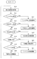
- FIG. 14 is a flowchart of processing in the “floor reflection” state by the state determination unit 50.
- the state determination unit 50 first refers to the detection region database 30 (step S191), and acquires the latest detection result information and past detection result information.
- the state determination unit 50 determines whether or not to return to the “normal” state using the latest detection result information and the past detection result information (step S192). If the condition for returning to the “normal” state is satisfied (YES in step S192), the state transitions to the “normal” state (step S193), and the process returns to step S10.
- step S192 When the condition for returning to the “normal” state is not satisfied (NO in step S192), the state type information indicating the “floor reflection” state is output to the reference point creating unit 60 (step S194), and the next image frame After waiting for the detection result information to be accumulated in the detection area database 30, the process returns to step S191.
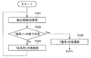
- FIG. 15 is a flowchart of the process of the “shielding” state by the state determination unit 50.
- the state determination unit 50 refers to the detection area database 30 (step S201), and acquires the latest detection result information and past detection result information.
- the state determination unit 50 determines whether to return to the “normal” state using the latest detection result information and past detection result information (step S202). If the condition for returning to the “normal” state is satisfied (YES in step S202), the state transitions to the “normal” state (step S203), and the process returns to step S10.
- step S202 If the condition for returning to the “normal” state is not satisfied (NO in step S202), the state type information indicating the “shielded” state is output to the reference point creating unit 60 (step S204), and the next image frame is displayed.
- the process waits for the detection result information to be accumulated in the detection area database 30, and returns to step S201.
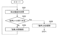
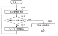
- FIG. 16 is a flowchart of the “noise” state processing by the state determination unit 50.
- the state determination unit 50 refers to the detection area database 30 (step S211), and acquires the latest detection result information and past detection result information.
- the state determination unit 50 determines whether to return to the “normal” state using the latest detection result information and past detection result information (step S212). If the condition for returning to the “normal” state is satisfied (YES in step S212), the state transitions to the “normal” state (step S213), and the process returns to step S10. If the condition for returning to the “normal” state is not satisfied (NO in step S212), the state type information indicating the “noise” state is output to the reference point creating unit 60 (step S214), and the next image frame is displayed. The process waits for the detection result information to be accumulated in the detection area database 30, and returns to step S211.
- the state determination unit 50 determines that one detection result information is in the “noise” state, the state determination unit 50 outputs state type information indicating the “noise” state to the reference point creation unit 60, as described above.
- the reference point creation unit 60 Upon receiving the state type information indicating the “noise” state, the reference point creation unit 60 does not immediately create a reference point, but uses (averages) the reference point using a plurality of detection result information in which the “noise” state continues.
- the present invention is not limited to such processing.
- the state type information is not output to the reference point creation unit 60, and after returning to the “normal” state, The state type information indicating the “noise” state may be output to the reference point creation unit 60 together with the time information therebetween.
- the state determination unit 50 determines the state of the tracking target
- the reference point generation unit 60 responds to the state determined by the state determination unit 50. Since the reference point is created, it is possible to reduce creation of an erroneous flow line that creates a flow line indicating that the tracking target has moved even though the tracking target has not moved.
- the state determination unit 50 may be configured to be able to determine the state of “squatting” and “floor reflection”.
- the reference point may be determined using another location such as the center of the underline of the rectangle. Also good. In that case, the method for creating the reference point in each of the "Crouching”, “Stretching”, “Floor Reflection”, “Shielding”, and “Noise” statuses also matches the reference point position in the "Normal” state. Change it.
- the state determination unit 50 may be configured to determine that the state has transitioned from the “squatting” state to the “hand stretched” state.
- the “squatting” determination, the “hand stretched” determination, the “floor reflection” determination, the “shielding” determination, and the “noise” determination are the operation flow shown in FIG.
- the order is arbitrary, and a plurality of determinations may be performed in parallel.
- the flow line creation device that determines all of the “squatting” determination, the “hand stretching” determination, the “floor reflection” determination, the “shielding” determination, and the “noise” determination has been described.
- the flow line creation device of the present invention may perform only a part of these determinations.
- the flow line creation device has the effect of reducing the creation of an erroneous flow line that creates a flow line that does not accurately reflect the movement of the tracking target without increasing the processing load.
- the present invention can be applied to a flow line creation device that detects a tracking target in an image and creates a flow line representing the movement trajectory of the tracking target.
Landscapes
- Engineering & Computer Science (AREA)
- Multimedia (AREA)
- Physics & Mathematics (AREA)
- General Physics & Mathematics (AREA)
- Theoretical Computer Science (AREA)
- Computer Vision & Pattern Recognition (AREA)
- Image Analysis (AREA)
- Traffic Control Systems (AREA)
Abstract
Description
yut=yot-ht ……(1)
xrt=xlt+wt ……(2)
まず、「通常」状態である場合の基準点の作成方法を説明する。「通常」状態である場合は、矩形枠の中心点を基準点とする。即ち、ある時刻t1において「通常」状態であるとすると、その時刻t1における基準点のx座標及びy座標は、それぞれ下式(3)及び(4)によって表される。
x=(xrt1+xlt1)/2 ……(3)
y=(yot1+yut1)/2 ……(4)
x=xlt1+wt1/2 ……(3’)
y=yot1-ht1/2 ……(4’)
図6は、「通常」状態から「しゃがみ」状態への遷移の判定条件及び「しゃがみ」状態の基準点の作成を説明する図である。図6は、時刻t1に「通常」状態であった追跡対象が、時刻t2に「しゃがみ」状態になった様子を示している。通常、人間がしゃがんだ場合には、足元の位置は変わらず、頭部の位置が下がる。このとき、矩形枠は、下線の位置がほぼ変わらず、上線の位置のみが大きく下に下がることになる。
条件1:|yut1-yut2|<ε1
条件2:yot1-yot2>a
条件1は、ε1を誤差範囲として、矩形枠の下座標の差分がその誤差範囲内にあるという条件である。条件2は、矩形枠の上座標が閾値a以上小さくなるという条件である。なお、この条件が一定時間以上継続して満たされた場合に、追跡対象が「しゃがみ」状態になったと判定してもよい。
x=(xrt2+xlt2)/2 ……(5)
y=(yot1+yut2)/2 ……(6)
ここで、「通常」状態であった最後の時刻(時刻t1)の上座標yot1を用いて、「しゃがみ」状態である時刻t2の基準点のy座標を求めていることが特徴的である。即ち、「しゃがみ」状態である場合も「通常」状態の場合と同様に、矩形枠の中心点を基準点とするが、この矩形枠の上座標として、「しゃがみ」状態となった時刻の上座標ではなく、最後に「通常」状態であった時刻の上座標を採用する。
状態判定部50は、時刻t2においてある追跡IDの追跡対象が「しゃがみ」状態である場合に、同一の追跡IDの追跡対象について、時刻t3に下記の条件3及び条件4の少なくともいずれか一方を満たした場合には、その時刻t3において「しゃがみ」状態から「通常」状態に戻ったと判定する。
条件3:|yut2-yut3|>b
条件4:yot1-yot3<ε2
図7は、「通常」状態から「手伸ばし」状態への遷移の判定条件及び「手伸ばし」状態の基準点の作成を説明する図である。図7は、時刻t1に「通常」状態であった追跡対象が、時刻t2に「手伸ばし」状態になった様子を示している。通常、人物が手を伸ばした場合には、頭部及び脚部の位置は変わらず、手が左又は右に伸びる。このとき、矩形枠は、上線及び下線の位置がほぼ変わらず、枠幅が増大することになる。
条件5:|yut1-yut2|<ε3
条件6:|yot1-yot2|<ε4
条件7:(xrt2-xlt2)-(xrt1-xlt1)>c
条件5は、ε3を誤差範囲として、矩形枠の下座標の差分がその誤差範囲内にあるという条件である。条件6は、ε4を誤差範囲として、矩形枠の上座標の差分がその誤差範囲内にあるという条件である。条件7は、矩形枠の枠幅が閾値c以上増大するという条件である。なお、この条件が一定時間以上継続して満たされた場合に、追跡対象が「手伸ばし」状態になったと判定してもよい。
x=(xrt2+xlt1)/2 ……(7)
y=(yot2+yut2)/2 ……(8)
ここで、「通常」状態であった最後の時刻(時刻t1)の左座標xlt1を用いて、「右手伸ばし」状態である時刻t2の基準点のx座標を求めていることが特徴的である。即ち、「右手伸ばし」状態である場合も「通常」状態の場合と同様に、矩形枠の中心点を基準点とするが、この矩形枠の左座標として、「右手伸ばし」状態となった時刻の左座標ではなく、最後に「通常」状態であった時刻の左座標を採用する。
x=(xrt1+xlt2)/2 ……(9)
y=(yot2+yut2)/2 ……(10)
ここで、「通常」状態であった最後の時刻(時刻t1)の右座標xrt1を用いて、「左手伸ばし」状態である時刻t2の基準点のx座標を求めていることが特徴的である。即ち、「左手伸ばし」状態である場合も「通常」状態の場合と同様に、矩形枠の中心点を基準点とするが、この矩形枠の右座標として、「左手伸ばし」状態となった時刻の右座標ではなく、最後に「通常」状態であった時刻の右座標を採用する。
状態判定部50は、時刻t2においてある追跡IDの追跡対象が「手伸ばし」状態である場合に、同一の追跡IDの追跡対象について、時刻t3に下記の条件8を満たすか、又は条件9及び条件10の両方を満たした場合には、その時刻t3において「手伸ばし」状態から「通常」状態に戻ったと判定する。
条件8:|(yot2-yut2)-(yot3-yut3)|>d
条件9:|(yot2-yut2)-(yot3-yut3)|<ε5
条件10:|(xrt3-xlt3)-(xrt1-xlt1)|<ε6
図8は、「通常」状態から「床反射」状態への遷移の判定条件及び「床反射」状態の基準点の作成を説明する図である。図8は、時刻t1に「通常」状態であった追跡対象が、時刻t2に「床反射」状態になった様子を示している。上述のように、物体検出部20は、過去の画像と現在の画像との差分を用いて追跡対象を検出するので、人物が反射しやすい領域にいる場合には、人物を反射する床の部分も差分領域となってしまい、矩形枠が実際の人物よりも大きく設定されてしまう。
条件11:(xrt2-300)2+(yut2-400)2<1600
条件12:(xlt2-300)2+(yut2-400)2<1600
条件11は、下線の右の端点が床反射領域内にあるという条件である。条件12は、下線の左の端点が床反射領域内にあるという条件である。なお、これら条件が一定時間以上継続して満たされた場合に、追跡対象がそれぞれの「床反射」状態にあると判定してもよい。
x=(xrt2+xlt2)/2 ……(11)
y=(yot2+yut1)/2 ……(12)
ここで、「通常」状態であった最後の時刻(時刻t1)の下座標yut1を用いて、「床反射」状態である時刻t2の基準点のy座標を求めていることが特徴的である。即ち、「床反射」状態である場合も「通常」状態の場合と同様に、矩形枠の中心点を基準点とするが、この矩形枠の下座標として、「床反射」状態である時刻の下座標ではなく、最後に「通常」状態であった時刻の下座標を採用する。
状態判定部50は、時刻t2においてある追跡IDの追跡対象が「床反射」状態である場合に、同一の追跡IDの追跡対象について、時刻t3に、下線の端点が上記の条件11及び条件12のいずれも満たさなくなった場合には、その時刻t3において「床反射」状態から「通常」状態に戻ったと判定する。
図9は、「通常」状態から「遮蔽」状態への遷移の判定条件及び「遮蔽」状態の基準点の作成を説明する図である。図9は、時刻t1に「通常」状態であった追跡対象が、時刻t2に「遮蔽」状態になった様子を示している。通常、人物が遮蔽物の陰に隠れている場合には、過去の画像と現在の画像との差分を用いて追跡対象を検出すると、矩形枠が実際の人物よりも小さく設定されてしまう。
条件13:100<xlt2<200
条件14:100<xrt2<200
条件15:250<yut2<350
x=(xrt2+xlt2)/2 ……(13)
y=(yot2+yut1)/2 ……(14)
ここで、「通常」状態であった最後の時刻(時刻t1)の下座標yut1を用いて、「遮蔽」状態である時刻t2の基準点のy座標を求めていることが特徴的である。即ち、「遮蔽」状態である場合も「通常」状態の場合と同様に、矩形枠の中心点を基準点とするが、この矩形枠の下座標として、「遮蔽」状態となった時刻の下座標ではなく、最後に「通常」状態であった時刻の下座標を採用する。
状態判定部50は、時刻t2においてある追跡IDの追跡対象が「遮蔽」状態である場合に、同一の追跡IDの追跡対象について、時刻t3に、上記の条件13ないし条件15の少なくともいずれか1つを満たさなくなった場合には、その時刻t3において「遮蔽」状態から「通常」状態に戻ったと判定する。
上記で説明した判定条件を用いても、「しゃがみ」、「手伸ばし」、「床反射」、「遮蔽」の何れの状態にも該当しないが、矩形枠の枠幅と枠高との比や枠の大きさが短時間で大きく変動する場合には、何らかのノイズによるものであると判断できる。
x=(Σ(xrt+xlt)/2)/n ……(15)
y=(Σ(yot+yut)/2)/n ……(16)
10 カメラ
20 物体検出部
30 検出領域データベース
40 環境データベース
50 状態判定部
60 基準点作成部
70 動線作成部
Claims (11)
- 追跡対象の移動軌跡を表す動線を作成する動線作成装置において、
画像フレームから追跡対象を検出して、前記追跡対象の検出領域を含む検出結果情報を生成する物体検出部と、
前記検出結果情報に基づいて、前記追跡対象の状態を判定する状態判定部と、
前記状態判定部にて判定された状態に対応する方法で前記検出領域を用いて、前記追跡対象の基準点を作成する基準点作成部と、
複数の前記画像フレームについて作成された複数の前記基準点を結んで、前記追跡対象の移動軌跡を表す動線を生成する動線作成部と、
を備えたことを特徴とする動線作成装置。 - 前記状態判定部は、前記検出領域の変化に基づいて、前記追跡対象の状態を判定することを特徴とする請求項1に記載の動線作成装置。
- 前記状態判定部は、動線作成の対象空間に設定された環境情報と前記検出領域との位置関係に基づいて、前記追跡対象の状態を判定することを特徴とする請求項1又は2に記載の動線作成装置。
- 前記基準点作成部は、前記状態判定部にて通常の状態ではない特定の状態であると判定されたときは、現在及び過去の前記検出領域を用いて前記基準点を作成することを特徴とする請求項1ないし請求項3のいずれかに記載の動線作成装置。
- 前記物体検出部は、前記検出領域として、上線、下線、右線、及び左線から構成され、検出した追跡対象を包含する矩形枠を生成することを特徴とする請求項1ないし請求項4のいずれかに記載の動線作成装置。
- 前記状態判定部は、現在の矩形枠と過去の矩形枠とを比較して、下線の移動が第1の閾値より小さく、上線の下方向への移動が第2の閾値より大きいときは、しゃがみ状態であると判定し、
前記基準点作成部は、前記状態判定部にてしゃがみ状態であると判定されたときは、前記矩形枠の上線として、前記過去の矩形枠の上線を採用して、基準点を作成することを特徴とする請求項5に記載の動線作成装置。 - 前記状態判定部は、現在の矩形枠と過去の矩形枠とを比較して、上線及び下線の移動が第3の閾値より小さく、右線の右方向への移動又は左線の左方向への移動が第4の閾値より大きいときは、手伸ばし状態であると判定し、
前記基準点作成部は、前記状態判定部にて手伸ばし状態であると判定されたときは、前記矩形枠の右線又は左線として、前記過去の矩形枠の右線又は左線を採用して、基準点を作成することを特徴とする請求項5又は6に記載の動線作成装置。 - 前記状態判定部は、現在の検出結果情報の矩形枠の下線の端点の少なくとも1つが、動線作成の対象空間に設定された床反射領域に含まれているときは、床反射状態であると判定し、
前記基準点作成部は、前記状態判定部にて床反射状態であると判定されたときは、前記矩形枠の下線として、過去の検出結果情報の矩形枠の下線を採用して、基準点を作成することを特徴とする請求項5ないし請求項7のいずれかに記載の動線作成装置。 - 前記状態判定部は、現在の検出結果情報の矩形枠の下線が、動線作成の対象空間に設定された遮蔽領域に含まれているときは、遮蔽状態であると判定し、
前記基準点作成部は、前記状態判定部にて遮蔽状態であると判定されたときは、前記矩形枠の下線として、過去の検出結果情報の矩形枠の下線を採用して、基準点を作成することを特徴とする請求項5ないし請求項8のいずれかに記載の動線作成装置。 - 前記状態判定部は、通常の状態以外の特定の状態に該当しないが、検出結果情報の矩形枠の縦横比又は大きさが第5の閾値を越えて変化したときは、ノイズ状態であると判定し、
前記基準点作成部は、前記状態判定部にてノイズ状態であると判定されたときは、ノイズ状態であると判定された期間の複数の前記矩形枠を平均化して、基準点を作成することを特徴とする請求項5ないし請求項9のいずれかに記載の動線作成装置。 - 追跡対象の移動軌跡を表す動線を作成する動線作成方法において、
画像フレームから追跡対象を検出して、前記追跡対象の検出領域を含む検出結果情報を生成する物体検出ステップと、
前記検出結果情報に基づいて、前記追跡対象の状態を判定する状態判定ステップと、
前記状態判定ステップにて判定された状態に対応する方法で前記検出領域を用いて、前記追跡対象の基準点を作成する基準点作成ステップと、
複数の前記画像フレームについて作成された複数の前記基準点を結んで、前記追跡対象の移動軌跡を表す動線を生成する動線作成ステップと、
を含むことを特徴とする動線作成方法。
Priority Applications (2)
| Application Number | Priority Date | Filing Date | Title |
|---|---|---|---|
| US13/639,655 US8934671B2 (en) | 2010-05-21 | 2011-01-07 | Traffic line creation device and traffic line creation method |
| CN201180025323.0A CN102906788B (zh) | 2010-05-21 | 2011-01-07 | 动线制作装置及动线制作方法 |
Applications Claiming Priority (2)
| Application Number | Priority Date | Filing Date | Title |
|---|---|---|---|
| JP2010117284A JP5567899B2 (ja) | 2010-05-21 | 2010-05-21 | 動線作成装置及び動線作成方法 |
| JP2010-117284 | 2010-05-21 |
Publications (1)
| Publication Number | Publication Date |
|---|---|
| WO2011145236A1 true WO2011145236A1 (ja) | 2011-11-24 |
Family
ID=44991359
Family Applications (1)
| Application Number | Title | Priority Date | Filing Date |
|---|---|---|---|
| PCT/JP2011/000030 WO2011145236A1 (ja) | 2010-05-21 | 2011-01-07 | 動線作成装置及び動線作成方法 |
Country Status (4)
| Country | Link |
|---|---|
| US (1) | US8934671B2 (ja) |
| JP (1) | JP5567899B2 (ja) |
| CN (1) | CN102906788B (ja) |
| WO (1) | WO2011145236A1 (ja) |
Families Citing this family (9)
| Publication number | Priority date | Publication date | Assignee | Title |
|---|---|---|---|---|
| EP2811736A4 (en) | 2012-01-30 | 2014-12-10 | Panasonic Corp | OPTIMUM CAMERA SETUP DEVICE AND OPTIMUM CAMERA SETTING METHOD |
| JP6206804B2 (ja) | 2013-09-27 | 2017-10-04 | パナソニックIpマネジメント株式会社 | 移動体追跡装置、移動体追跡システムおよび移動体追跡方法 |
| JP6336872B2 (ja) * | 2014-09-29 | 2018-06-06 | Kddi株式会社 | オブジェクト追跡方法、装置およびプログラム |
| JP6119794B2 (ja) * | 2015-04-28 | 2017-04-26 | マツダ株式会社 | 歩行者移動推定方法および推定装置 |
| JP6812643B2 (ja) * | 2016-03-07 | 2021-01-13 | 株式会社リコー | 通信端末、画像通信システム、表示方法、及びプログラム |
| US10277836B2 (en) | 2016-03-07 | 2019-04-30 | Ricoh Company, Ltd. | Communication terminal, image management apparatus, image processing system, method for controlling display, and computer program product |
| JP6972798B2 (ja) * | 2016-11-22 | 2021-11-24 | 株式会社リコー | 情報処理装置、撮像装置、機器制御システム、移動体、情報処理方法、及びプログラム |
| CN111444892B (zh) * | 2020-05-05 | 2023-12-15 | 商志营 | 一种基于动线的轨迹追踪系统、查询方法及装置 |
| JP7478306B2 (ja) | 2021-03-19 | 2024-05-02 | 株式会社日立国際電気 | 画像解析装置、画像解析システム及び画像解析方法 |
Citations (2)
| Publication number | Priority date | Publication date | Assignee | Title |
|---|---|---|---|---|
| JPH056434A (ja) * | 1991-06-27 | 1993-01-14 | Matsushita Electric Ind Co Ltd | 自動追尾装置 |
| JPH09130784A (ja) * | 1995-08-25 | 1997-05-16 | Matsushita Electric Works Ltd | 自動追尾方法及びその装置 |
Family Cites Families (6)
| Publication number | Priority date | Publication date | Assignee | Title |
|---|---|---|---|---|
| JP2000268173A (ja) * | 1999-03-17 | 2000-09-29 | Hitachi Denshi Ltd | 物体認識画像処理方法 |
| CN1770204A (zh) * | 2004-10-29 | 2006-05-10 | 中国科学院计算技术研究所 | 从具有静态背景的运动视频提取运动对象重心轨迹的方法 |
| US7606411B2 (en) * | 2006-10-05 | 2009-10-20 | The United States Of America As Represented By The Secretary Of The Navy | Robotic gesture recognition system |
| JP4760655B2 (ja) * | 2006-10-12 | 2011-08-31 | パナソニック電工株式会社 | 人体検出装置 |
| JP4429337B2 (ja) | 2007-06-28 | 2010-03-10 | 東芝テック株式会社 | 動線処理装置,方法及びプログラム |
| CN101465033B (zh) * | 2008-05-28 | 2011-01-26 | 丁国锋 | 一种自动追踪识别系统及方法 |
-
2010
- 2010-05-21 JP JP2010117284A patent/JP5567899B2/ja active Active
-
2011
- 2011-01-07 CN CN201180025323.0A patent/CN102906788B/zh not_active Expired - Fee Related
- 2011-01-07 WO PCT/JP2011/000030 patent/WO2011145236A1/ja active Application Filing
- 2011-01-07 US US13/639,655 patent/US8934671B2/en active Active
Patent Citations (2)
| Publication number | Priority date | Publication date | Assignee | Title |
|---|---|---|---|---|
| JPH056434A (ja) * | 1991-06-27 | 1993-01-14 | Matsushita Electric Ind Co Ltd | 自動追尾装置 |
| JPH09130784A (ja) * | 1995-08-25 | 1997-05-16 | Matsushita Electric Works Ltd | 自動追尾方法及びその装置 |
Also Published As
| Publication number | Publication date |
|---|---|
| JP2011243155A (ja) | 2011-12-01 |
| US8934671B2 (en) | 2015-01-13 |
| JP5567899B2 (ja) | 2014-08-06 |
| CN102906788A (zh) | 2013-01-30 |
| US20130022246A1 (en) | 2013-01-24 |
| CN102906788B (zh) | 2016-06-08 |
Similar Documents
| Publication | Publication Date | Title |
|---|---|---|
| WO2011145236A1 (ja) | 動線作成装置及び動線作成方法 | |
| EP2544149A1 (en) | Moving-body detection device, moving-body detection method, moving-body detection program, moving-body tracking device, moving-body tracking method, and moving-body tracking program | |
| KR101606628B1 (ko) | 포인팅 방향 검출 장치 및 그 방법과, 프로그램 및 컴퓨터 판독가능한 매체 | |
| EP2908220A1 (en) | Gesture recognition device and method of controlling gesture recognition device | |
| US9128526B2 (en) | Operation control device, operation control method, and computer-readable recording medium for distinguishing an intended motion for gesture control | |
| JP4919036B2 (ja) | 移動物体認識装置 | |
| JP5756709B2 (ja) | 身長推定装置、身長推定方法、及び身長推定プログラム | |
| JP2011170684A (ja) | 対象物追跡装置、対象物追跡方法、および対象物追跡プログラム | |
| CN108140291A (zh) | 烟雾检测装置、方法以及图像处理设备 | |
| JP5510907B2 (ja) | タッチ位置入力装置及びタッチ位置入力方法 | |
| TWI441060B (zh) | 一種光學觸控系統之影像處理方法 | |
| US9025022B2 (en) | Method and apparatus for gesture recognition using a two dimensional imaging device | |
| JP2006236184A (ja) | 画像処理による人体検知方法 | |
| CN111986229A (zh) | 视频目标检测方法、装置及计算机系统 | |
| WO2022123929A1 (ja) | 情報処理装置及び情報処理方法 | |
| JP2010271876A (ja) | 移動体追跡装置、移動体追跡方法及びプログラム | |
| US10922864B2 (en) | Image processing device, image processing method and program, for object detection in an image | |
| US9535535B2 (en) | Touch point sensing method and optical touch system | |
| JP5470529B2 (ja) | 動き検出装置、動き検出方法及び動き検出プログラム | |
| KR101837482B1 (ko) | 영상처리방법 및 장치, 그리고 이를 이용한 제스처 인식 인터페이스 방법 및 장치 | |
| Niikura et al. | Touch detection system for various surfaces using shadow of finger | |
| JP2014109875A (ja) | 交差点検出方法および交差点検出システム | |
| TWI475447B (zh) | 光學觸控系統及其觸控點計算方法 | |
| TWI529608B (zh) | 一種手勢辨識追蹤方法及其系統 | |
| JP2015022730A (ja) | 画像処理装置、画像処理方法および画像処理プログラム |
Legal Events
| Date | Code | Title | Description |
|---|---|---|---|
| WWE | Wipo information: entry into national phase |
Ref document number: 201180025323.0 Country of ref document: CN |
|
| 121 | Ep: the epo has been informed by wipo that ep was designated in this application |
Ref document number: 11783175 Country of ref document: EP Kind code of ref document: A1 |
|
| WWE | Wipo information: entry into national phase |
Ref document number: 13639655 Country of ref document: US |
|
| NENP | Non-entry into the national phase |
Ref country code: DE |
|
| 122 | Ep: pct application non-entry in european phase |
Ref document number: 11783175 Country of ref document: EP Kind code of ref document: A1 |