WO2011142250A1 - クラッチ装置 - Google Patents
クラッチ装置 Download PDFInfo
- Publication number
- WO2011142250A1 WO2011142250A1 PCT/JP2011/060124 JP2011060124W WO2011142250A1 WO 2011142250 A1 WO2011142250 A1 WO 2011142250A1 JP 2011060124 W JP2011060124 W JP 2011060124W WO 2011142250 A1 WO2011142250 A1 WO 2011142250A1
- Authority
- WO
- WIPO (PCT)
- Prior art keywords
- input shaft
- shaft
- input
- clutch
- engine
- Prior art date
- Legal status (The legal status is an assumption and is not a legal conclusion. Google has not performed a legal analysis and makes no representation as to the accuracy of the status listed.)
- Ceased
Links
Images



Classifications
-
- F—MECHANICAL ENGINEERING; LIGHTING; HEATING; WEAPONS; BLASTING
- F16—ENGINEERING ELEMENTS AND UNITS; GENERAL MEASURES FOR PRODUCING AND MAINTAINING EFFECTIVE FUNCTIONING OF MACHINES OR INSTALLATIONS; THERMAL INSULATION IN GENERAL
- F16D—COUPLINGS FOR TRANSMITTING ROTATION; CLUTCHES; BRAKES
- F16D21/00—Systems comprising a plurality of actuated clutches
- F16D21/02—Systems comprising a plurality of actuated clutches for interconnecting three or more shafts or other transmission members in different ways
- F16D21/06—Systems comprising a plurality of actuated clutches for interconnecting three or more shafts or other transmission members in different ways at least two driving shafts or two driven shafts being concentric
-
- F—MECHANICAL ENGINEERING; LIGHTING; HEATING; WEAPONS; BLASTING
- F16—ENGINEERING ELEMENTS AND UNITS; GENERAL MEASURES FOR PRODUCING AND MAINTAINING EFFECTIVE FUNCTIONING OF MACHINES OR INSTALLATIONS; THERMAL INSULATION IN GENERAL
- F16D—COUPLINGS FOR TRANSMITTING ROTATION; CLUTCHES; BRAKES
- F16D13/00—Friction clutches
- F16D13/22—Friction clutches with axially-movable clutching members
- F16D13/38—Friction clutches with axially-movable clutching members with flat clutching surfaces, e.g. discs
-
- F—MECHANICAL ENGINEERING; LIGHTING; HEATING; WEAPONS; BLASTING
- F16—ENGINEERING ELEMENTS AND UNITS; GENERAL MEASURES FOR PRODUCING AND MAINTAINING EFFECTIVE FUNCTIONING OF MACHINES OR INSTALLATIONS; THERMAL INSULATION IN GENERAL
- F16D—COUPLINGS FOR TRANSMITTING ROTATION; CLUTCHES; BRAKES
- F16D21/00—Systems comprising a plurality of actuated clutches
- F16D21/02—Systems comprising a plurality of actuated clutches for interconnecting three or more shafts or other transmission members in different ways
- F16D21/06—Systems comprising a plurality of actuated clutches for interconnecting three or more shafts or other transmission members in different ways at least two driving shafts or two driven shafts being concentric
- F16D2021/0684—Mechanically actuated clutches with two clutch plates
-
- F—MECHANICAL ENGINEERING; LIGHTING; HEATING; WEAPONS; BLASTING
- F16—ENGINEERING ELEMENTS AND UNITS; GENERAL MEASURES FOR PRODUCING AND MAINTAINING EFFECTIVE FUNCTIONING OF MACHINES OR INSTALLATIONS; THERMAL INSULATION IN GENERAL
- F16D—COUPLINGS FOR TRANSMITTING ROTATION; CLUTCHES; BRAKES
- F16D21/00—Systems comprising a plurality of actuated clutches
- F16D21/02—Systems comprising a plurality of actuated clutches for interconnecting three or more shafts or other transmission members in different ways
- F16D21/06—Systems comprising a plurality of actuated clutches for interconnecting three or more shafts or other transmission members in different ways at least two driving shafts or two driven shafts being concentric
- F16D2021/0692—Systems comprising a plurality of actuated clutches for interconnecting three or more shafts or other transmission members in different ways at least two driving shafts or two driven shafts being concentric with two clutches arranged axially without radial overlap
Definitions
- the present invention relates to a clutch device for transmitting power from a power source such as an engine or a motor to a transmission.
- An automatic transmission is known as a means for automatically shifting a vehicle.
- a combination of a torque converter, a plurality of planetary gears, and a clutch has become mainstream.
- an AT for example, a torque converter transmits power via a fluid
- the power transmission efficiency is lower than that of a manual transmission (MT) that mechanically directly connects the input side and the output side to transmit torque.
- MT manual transmission
- the AT has an advantage that the labor of the driver is reduced, but has a disadvantage that the fuel consumption of the vehicle is reduced.
- an automatic transmission (AMT) has been proposed that aims to eliminate the need for clutch operation while ensuring MT transmission efficiency (see, for example, Patent Document 1).
- This automatic transmission can automate the clutch operation of the MT and the transmission operation of the transmission, and can eliminate the need for the clutch operation while ensuring the same transmission efficiency as the conventional MT.
- the clutch device described in Patent Document 1 mainly includes a cover member including a pair of flywheels, a pair of pressure plates disposed between the pair of flywheels, and a pair of pressure plates that are pressed by the pair of pressure plates, respectively. Has a clutch disk.
- Such a dual type clutch device transmits power from the engine to the transmission via two shafts for transmitting power to the transmission.
- the two shafts for transmitting power to the transmission are composed of an inner shaft and an outer shaft.
- the clutch device in a state where the clutch device is mainly supported by the inner shaft, the power from the engine is transmitted to the transmission by rotating about the same axis as each shaft.
- the conventional dual type clutch device has its own weight mainly supported by the inner shaft.
- thrust force is also transmitted to the inner shaft in addition to its own weight.
- the inner shaft has to have a small shaft diameter due to the configuration, if the inner shaft rotates with the inner shaft supporting the own weight and thrust force of the clutch device, resonance or the like occurs during this rotation. As a result, transmission of power from the engine to the transmission may become unstable.
- the present invention has been made in view of such problems, and an object of the present invention is to provide a clutch device capable of stably transmitting power from an engine to a transmission.
- the clutch device according to claim 1 is a clutch device for transmitting power from an engine to a transmission having a first input shaft and a second input shaft having a diameter larger than that of the first input shaft.
- This clutch device includes an input rotator, a first pressure plate, a second pressure plate, a first clutch disk assembly, a second clutch disk assembly, and a rotation support mechanism.
- the input rotator includes a first disk part and a second disk part arranged with a space from the first disk part.
- the first pressure plate is disposed in the input rotating body, and is disposed so as to be integrally rotatable with respect to the first disk portion and movable in the axial direction.
- the second pressure plate is disposed in the input rotating body, and is disposed so as to be integrally rotatable with respect to the second disk portion and movable in the axial direction.
- the first clutch disc assembly has a first friction portion disposed between the first disc portion and the first pressure plate, and is coupled to the first input shaft.
- the second clutch disk assembly has a second friction portion disposed between the second disk portion and the second pressure plate, and is coupled to the second input shaft.
- the rotation support mechanism is provided between the second input shaft and the input rotator, and shaft movement to the engine side is restricted. The rotation support mechanism supports the input rotator so as to be rotatable with respect to the first input shaft and the second input shaft.
- the engine power is moved from the first disk part via the first clutch disk assembly by moving the first pressure plate in the direction of the first disk part. It is transmitted to the first input shaft.
- the power of the engine moves the second pressure plate in the direction of the second disk portion, thereby moving the second disk portion through the second clutch disk assembly. To the second input shaft.
- the reaction force for pressing the first pressure plate or the second pressure plate is used. Thrust force is generated. This thrust force is input to the rotation support mechanism in which the shaft movement to the engine side is restricted, and is transmitted to the second input shaft.
- the present invention when power is transmitted from the engine to the transmission by restricting the shaft movement to the engine side of the rotation support mechanism provided between the second input shaft and the input rotating body.
- the generated thrust force can be transmitted to the second input shaft having a larger diameter than the first input shaft.
- the thrust force generated in the clutch device can be received by the second input shaft having higher rigidity than the first input shaft, power can be stably transmitted from the engine to the transmission. it can.
- a clutch device is the clutch device according to the first aspect, further comprising a shaft movement restricting mechanism.
- the shaft movement restricting mechanism is for restricting the shaft movement of the rotation support mechanism toward the engine, and is provided between the second input shaft and the rotation support mechanism so as not to rotate with respect to the second input shaft. Yes.
- the shaft movement restriction mechanism includes a support member that supports the rotation support mechanism between the second input shaft and the rotation support mechanism, A shaft movement restricting member for restricting shaft movement to the engine side.
- the rotation support mechanism is supported by the support member of the shaft movement restriction mechanism, and the shaft movement of the support member to the engine side is restricted by the shaft movement restriction member. Accordingly, the thrust force input to the rotation support mechanism can be received by the second input shaft having higher rigidity than the first input shaft via the shaft movement restriction mechanism. Thereby, power can be stably transmitted from the engine to the transmission.
- the second clutch disk assembly includes a shaft movement restricting mechanism that restricts the shaft movement of the rotation support mechanism toward the engine.
- the shaft movement to the engine side is restricted by the shaft movement restriction mechanism.
- the rotation support mechanism since the rotation support mechanism is restricted in the axial movement toward the engine by the shaft movement restriction mechanism included in the second clutch disk assembly, the thrust force input to the rotation support mechanism is applied to the first rotation force. It can be received by the second input shaft having higher rigidity than the input shaft. Thereby, power can be stably transmitted from the engine to the transmission.
- the shaft movement restricting mechanism supports the second friction portion and supports the rotation support mechanism between the second input shaft and the rotation support mechanism. It has a support member and a shaft movement restricting member that restricts the shaft movement of the support member toward the engine.
- the first friction portion and the rotation support mechanism are supported by the support member of the shaft movement restriction mechanism, and the shaft movement of the support member to the engine side is restricted by the shaft movement restriction member. Accordingly, the thrust force input to the rotation support mechanism can be received by the second input shaft having higher rigidity than the first input shaft via the shaft movement restriction mechanism. Thereby, power can be stably transmitted from the engine to the transmission.
- the thrust force generated when power is transmitted from the engine to the transmission by restricting the axial movement of the rotation support mechanism provided between the second input shaft and the input rotator to the engine side. Can be transmitted to the second input shaft having a larger diameter than the first input shaft.
- the thrust force generated in the clutch device can be received by the second input shaft having higher rigidity than the first input shaft, power can be stably transmitted from the engine to the transmission. it can.
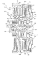
- the clutch device 1 is a device for transmitting power from an engine to a first input shaft 91 and a second input shaft 92 of a transmission, and includes an input rotator 10 and a first pressure.
- the input rotating body 10, the first pressure plate 39, the first clutch disk assembly 5, and the first drive mechanism 7 ⁇ / b> A of the drive mechanism 7 constitute a first clutch C ⁇ b> 1.
- the input clutch 10, the second pressure plate 49, the second clutch disk assembly 6, and the second drive mechanism 7 B of the drive mechanism 7 constitute a second clutch C 2.
- the first clutch C1 and the second clutch C2 are so-called normal open type clutches.
- the first clutch C1 transmits power at the first speed, the third speed, and the fifth speed
- the second clutch C2 transmits power at the second speed and the fourth speed.
- the first input shaft 91 is formed with a step portion 91a, an annular groove 91b, and a spline shaft 91c.
- the spline shaft 91 c is formed in the axial direction on the outer peripheral surface on the distal end side of the first input shaft 91.
- the step portion 91a is formed on the outer periphery of the spline shaft 91c on the transmission side of the spline shaft 91c.
- the annular groove 91 b is formed on the outer periphery on the distal end side of the first input shaft 91.
- the annular groove 91b is formed on the outer periphery of the spline shaft 91c on the engine side of the spline shaft 91c.
- a spline shaft 92 b is formed on the outer peripheral surface on the distal end side of the second input shaft 92.
- An annular groove 92 a is formed on the outer peripheral surface of the second input shaft 92.
- the second input shaft 92 is formed so that the diameter of the second input shaft 92 is larger than the diameter of the first input shaft 91.
- the second input shaft 92 is formed such that the diameter of the outer peripheral surface on the transmission side with respect to the groove 92a is larger than the diameter of the outer peripheral surface on the engine side with respect to the groove 92a.
- the diameter of the outer peripheral surface on the transmission side of the second input shaft 92 is larger than the diameter of the outer peripheral surface of the spline shaft 92b of the second input shaft 92.
- the input rotator 10 is a member to which power is transmitted from the engine, and is connected to the crankshaft 99 via the flexible plate 93.
- the inner peripheral portion of the flexible plate 93 is fixed to the crankshaft 99 by bolts, and the outer peripheral portion of the flexible plate 93 is fixed to the input rotating body 10 by bolts (not shown).
- a bearing is fixed to the inner periphery of the crankshaft 99, and the tip of the first input shaft 91 is rotatably supported by this bearing.
- the input rotator 10 mainly includes a first flywheel 3 (first disc portion), a second flywheel 4 (second disc portion), and an intermediate plate 38.
- the intermediate plate 38 is sandwiched between the first flywheel 3 and the second flywheel 4, and can rotate integrally with the first flywheel 3 and the second flywheel 4.
- the first pressure plate 39 is elastically coupled to the intermediate plate 38 via an unillustrated first strap plate so as to be integrally rotatable and in the axial direction.
- the second pressure plate 49 is elastically coupled to the intermediate plate 38 in an axially rotatable manner via a second strap plate (not shown).
- the first pressure plate 39 is disposed in the input rotator 10 and is disposed so as to be able to rotate integrally with the first flywheel 3 and move in the axial direction.
- the first pressure plate 39 is disposed so as to face the first flywheel 3 in the axial direction.
- the first pressure plate 39 is formed with a first support portion 39a protruding outward in the radial direction.
- the 1st support part 39a is arrange
- the first pressure plate 39 is provided with a first protrusion (not shown) at a position different from the first support portion 39a with a predetermined interval in the circumferential direction.
- the first strap plate is fixed to the first pressure plate 39.
- Second Pressure Plate The second pressure plate 49 is disposed in the input rotary body 10 and is disposed so as to be capable of rotating integrally with the second flywheel 4 and moving in the axial direction.
- the second pressure plate 49 is disposed so as to face the second flywheel 4 in the axial direction.
- the second pressure plate 49 is formed with a second support portion 49a that protrudes radially outward.
- the second support portions 49a are arranged at a predetermined interval in the circumferential direction.
- the second pressure plate 49 is connected to the second drive support member 79 of the second drive mechanism 7B.
- the second pressure plate 49 is provided with second projecting portions (not shown) at a position different from the second support portion 49a with a predetermined interval in the circumferential direction.
- the second strap plate is fixed to the second pressure plate 49.
- First clutch disk assembly The first clutch disk assembly 5 is an assembly for transmitting power from the input rotating body 10 to the first input shaft 91, and supports a support mechanism 13, which will be described later, such as a first support member 35. Connected to the first input shaft 91.
- the first clutch disk assembly 5 includes a first friction part 57, a first input member 52, a first hub 51, and a plurality of first springs 55.
- the first friction portion 57 is disposed between the first flywheel 3 and the first pressure plate 39 in the axial direction.
- the first friction part 57 is slidably provided on the input rotating body 10 and the first pressure plate 39.
- the first input member 52 is a member to which power is transmitted from the first friction part 57, and is connected to the first friction part 57.
- a spline groove is formed on the inner peripheral surface of the first hub 51 for connection to a support mechanism 13 described later.
- the first hub 51 is connected to the first input shaft 91 via the support mechanism 13.
- the first spring 55 is supported by the first input member 52 so as to be elastically deformable, and elastically connects the first input member 52 and the first hub 51 in the rotational direction.
- Second Clutch Disc Assembly The second clutch disc assembly 6 is an assembly for transmitting power from the input rotating body 10 to the second input shaft 92, and is connected to the second input shaft 92.
- the second clutch disk assembly 6 includes a second friction portion 67, a second input member 62, a second hub 61, and a plurality of second springs 65.
- the second friction portion 67 is disposed between the second flywheel 4 and the second pressure plate 49 in the axial direction.
- the second friction part 67 is slidably provided on the input rotating body 10 and the second pressure plate 49.
- the second input member 62 is a member to which power is transmitted from the second friction portion 67 and is connected to the second friction portion 67.
- a spline groove is formed on the inner peripheral surface of the second hub 61, and the second hub 61 is connected to the second input shaft 92 by the spline groove.
- the second spring 65 is supported by the second input member 62 so as to be elastically deformable, and elastically connects the second input member 62 and the second hub 61 in the rotational direction.
- Drive mechanism The drive mechanism 7 includes a first drive mechanism 7A and a second drive mechanism 7B.
- the first drive mechanism 7 ⁇ / b> A is a mechanism for operating power transmission of the first clutch C ⁇ b> 1, and transmits an axial pressing force to the first pressure plate 39.
- the first drive mechanism 7A includes a first drive support member 78 supported by the input rotator 10 and a first drive support member 78 that moves toward the first flywheel 3 with respect to the input rotator 10.
- the first driving force transmitting portion 71 that transmits the driving force to the driving support member 78 is provided.
- the second drive mechanism 7 ⁇ / b> B is a mechanism for operating the power transmission of the second clutch C ⁇ b> 2 and transmits an axial pressing force to the second pressure plate 49.
- the second drive mechanism 7B includes a second drive support member 79 supported by the input rotator 10, and a second drive mechanism 79 so that the second drive support member 79 moves toward the second flywheel 4 with respect to the input rotator 10.
- a second driving force transmission portion 72 that transmits a driving force to the driving support member 79 is provided.
- Rotation support mechanism The rotation support mechanism 11 includes a first rotation support mechanism 211 and a second rotation support mechanism 111.
- the first rotation support mechanism 211 is provided between the first input shaft 91 and the input rotator 10 and supports the input rotator 10 so as to be rotatable with respect to the first input shaft 91.
- the first rotation support mechanism 211 has a first bearing 34.
- the first bearing 34 is disposed between the first flywheel 3 and the first input shaft 91, and supports the first flywheel 3 to be rotatable with respect to the first input shaft 91.
- the first bearing 34 is disposed between the first flywheel 3 and the first support member 35, and supports the first flywheel 3 to be rotatable with respect to the first input shaft 91. Yes.
- the second rotation support mechanism 111 is provided between the second input shaft 92 and the input rotator 10, and supports the input rotator 10 to be rotatable with respect to the second input shaft 92.
- the second rotation support mechanism 111 has a second bearing 44.
- the second bearing 44 is disposed between the second flywheel 4 and the second input shaft 92, and supports the second flywheel 4 to be rotatable with respect to the second input shaft 92.
- the second bearing 44 is disposed between the second flywheel 4 and a shaft movement restricting mechanism 12 described later, and can rotate the second flywheel 4 with respect to the second input shaft 92. I support it.
- the second bearing 44 is mounted so as not to move in the axial direction with respect to the second flywheel 4 and the shaft movement restricting mechanism 12 described later by a pair of snap rings 20 and 21 facing in the axial direction.
- Axis Movement Restricting Mechanism The shaft movement restricting mechanism 12 is provided between the second input shaft 92 and the rotation support mechanism 11, that is, the second rotation support mechanism 111 so as not to rotate with respect to the second input shaft 92.
- the shaft movement of the rotation support mechanism 111 toward the engine is restricted.
- the shaft movement restriction mechanism 12 includes a second support member 45 and a shaft movement restriction member 46.
- the second support member 45 supports the second rotation support mechanism 111 between the second input shaft 92 and the second rotation support mechanism 111.
- the shaft movement restricting member for example, the snap ring 46 for the second input shaft restricts the shaft movement of the second support member 45 to the engine side.
- the second support member 45 is formed in a cylindrical shape.
- a protrusion 45a that protrudes radially outward on the engine side and supports the second bearing 44, and a snap ring that supports the second bearing 44 on the transmission side are fitted.
- an annular groove 45b On the inner peripheral surface of the second support member 45, a standby recess 45c in which the second input shaft snap ring 46 waits, a locking recess 45d in which the second input shaft snap ring 46 is locked, And a recovery recess 45e for recovering the snap ring 46 for the second input shaft.
- Spline grooves are formed in the axial direction on the inner peripheral surface of the second support member 45.
- the locking recess 45d is formed so that the inner diameter of the bottom of the locking recess 45d is smaller than the inner diameter of the bottom of the standby recess 45c.
- the locking recess 45d is formed so that the inner diameter of the bottom of the locking recess 45d is smaller than the inner diameter of the bottom of the recovery recess 45e.
- the snap ring 46 is formed so that the outer diameter of the snap ring 46 when free (the snap ring 46 before being attached to the second input shaft 92) is larger than the outer diameter of the recovery recess 45e. Further, the snap ring 46 is formed so that the inner diameter of the snap ring 46 when free is larger than the outer diameter of the spline 92 b of the second input shaft 92. Further, the snap ring 46 is formed so that the difference between the outer diameter and the inner diameter of the snap ring 46 is smaller than the height of the wall portion on the engine side of the recovery recess 45e. By forming the snap ring 46 in this way, the snap ring 46 can be reliably recovered in the recovery recess 45e. Support mechanism The support mechanism 13 includes a first support member 35.
- the 1st support member 35 is formed in the cylinder shape, and the spline groove
- the diameter of the outer peripheral surface on the transmission side of the second input shaft 92 (the diameter of the outer peripheral surface on the transmission side with respect to the groove portion 92a) is the diameter of the outer peripheral surface of the spline shaft 92b of the second input shaft 92 (groove portion 92a). Therefore, the movement of the snap ring 46 toward the transmission side can be restricted by the wall portion on the transmission side of the groove portion 92a of the second input shaft 92. In this state, a gap is provided between the inner peripheral surface of the snap ring 46 and the bottom of the groove 92 a of the second input shaft 92.
- the standby recess in the state in which the snap ring 46 is fitted to the standby recess 45c, that is, in contact with the wall surface of the standby recess 45 on the engine side.
- the tapered wall portion on the engine side of 45c is guided while being reduced in diameter from the standby recess 45c to the locking recess 45d, and is fitted into the groove 92a of the second input shaft 92.
- the snap ring 46 reaches the locking recess 45d, the snap ring 46 is expanded in diameter and fitted into the locking recess 45d. In this way, the snap ring 46 engages with the groove 92a and the locking recess 45d of the second input shaft 92, and restricts the axial movement of the second support member 45 toward the engine.
- the spline shaft 92b of the second input shaft 92 is formed between the tip end portion of the second input shaft 92 and the groove portion 92a. Specifically, the spline shaft 92b extends from the front end portion on the engine side to the transmission side on the outer peripheral surface of the second input shaft 92, and has a terminal end before reaching the groove portion 92a, that is, on the engine side of the groove portion 92a. Yes.
- the support mechanism 13, for example, the first support member 35 is mounted between the first input shaft 91 and the first rotation support mechanism 211 mounted on the first clutch disk assembly 5 and the first flywheel 3.
- the spline groove on the inner peripheral surface of the first support member 35 is fitted to the spline shaft of the first input shaft 91, and the spline shaft on the outer peripheral surface of the first support member 35 is connected to the first clutch disk assembly 5. Fits into the spline groove. And the clutch apparatus 1 moves to the transmission side along a spline.
- the snap ring 95 is attached to the annular groove 91 b of the first input shaft 91.
- the first support member 35 is positioned on the first input shaft 91.
- the clutch device 1 is mounted on the input shafts 91 and 92.
- the snap ring 95 for positioning the first support member 35 on the first input shaft 91 is removed.
- a removal jig (not shown) is attached to the first support member 35 via a bolt, and the first support member 35 is detached from the first input shaft 91 by moving the removal jig to the engine side. It is.
- the snap ring 46 is engaged with the locking recess 45d, that is, on the tapered wall portion on the engine side of the locking recess 45d.
- the guide In the abutting state, the guide is guided while reducing the diameter again from the locking recess 45d to the recovery recess 45e.
- the snap ring 46 reaches the recovery recess 45e, the snap ring 46 is expanded in diameter and recovered in the recovery recess 45e.
- the clutch device 1 is moved to the engine side along the spline, the first support member 35 is removed with the snap ring 46 recovered in the recovery recess 45e of the second support member 45.
- the clutch device 1 is removed from the input shafts 91 and 92.
- the operation of the clutch device 1 will be described.
- the state shown in FIG. 1 is a state in which no pressing force is applied to the first clutch C1 and the second clutch C2 by the drive mechanism 7, and no power is transmitted by the first clutch C1 and the second clutch C2. It is.
- the first pressure plate 39 is held at the axial position shown in FIG. 1
- the second pressure plate 49 is also held at the axial position shown in FIG.
- the input rotator 10 when power is transmitted from the engine to the input rotator 10, the input rotator 10, the first pressure plate 39, the second pressure plate 49, and the drive mechanism 7 rotate integrally.
- the first input shaft 91 supports the first bearing 34 via the support member 35, and the first bearing 34 supports the first flywheel 3 in a rotatable manner. Further, the second input shaft 92 supports the second bearing 44 via the shaft movement restricting mechanism 12, and the second bearing 44 supports the second flywheel 4 so as to be rotatable. Thereby, the rotation of the input rotating body 10 is stabilized.
- the first input shaft 91 side of the transmission is switched to the first speed, and the first drive mechanism 7A is pushed to the engine side by the first actuator (not shown). Then, the first drive support member 78 and the first pressure plate 39 move to the engine side. As a result, the first friction portion 57 of the first clutch disc assembly 5 is sandwiched between the first pressure plate 39 and the first flywheel 3, and the first input shaft 91 is interposed via the first clutch disc assembly 5. Power is transmitted to. By these operations, the vehicle starts to start at the first speed.
- the second input shaft 92 side of the transmission is switched to the second speed.
- the second clutch C2 is switched to the connected state almost simultaneously with the release of the first clutch C1. Specifically, the driving force applied to the first driving mechanism 7A is released. Then, the state of the first drive mechanism 7A returns to the state shown in FIG. 1, and the power transmission via the first clutch C1 is released.
- the first input shaft 91 side of the transmission is switched to the third speed.
- the first clutch C1 is switched to the connected state almost simultaneously with the release of the second clutch C2. Specifically, the driving force applied to the second drive mechanism 7B is released. Then, the state of the second drive mechanism 7B returns to the state shown in FIG. 1, and the power transmission via the second clutch C2 is released.
- the clutch device 1 when traveling at an odd speed, power is transmitted from the engine to the first input shaft 91 in which an odd number of gears is set. Further, when switching from odd speed to even speed during traveling, even gears are set on the second input shaft 92 in a state where power is transmitted from the engine to the first input shaft 91.
- the second clutch C2 is switched to the connected state almost simultaneously with the release of the first clutch C1
- power is transmitted from the engine to the second input shaft 92 in which an even number of gears is set.
- an odd number of gears is set on the first input shaft 91 in a state where power is transmitted from the engine to the second input shaft 92.
- the first clutch C1 is switched to the connected state almost simultaneously with the release of the second clutch C2
- power is transmitted from the engine to the first input shaft 91 in which an odd number of gears is set.
- the shaft movement restricting mechanism 12 includes a second support member 45 and a snap ring 46 for the second input shaft.
- the second support member 45 supports the second rotation support mechanism 111 between the second input shaft 92 and the second rotation support mechanism 111. Then, by engaging the second input shaft snap ring 46 with the second support member 45 and the second input shaft 92, the shaft movement of the second support member 45 toward the engine is restricted. In this way, the shaft movement restricting mechanism 12 restricts the shaft movement of the second rotation support mechanism 111 toward the engine between the second input shaft 92 and the second rotation support mechanism 111.
- the shaft movement of the second rotation support mechanism 111 relative to the second input shaft 92 toward the engine is restricted by the shaft movement restriction mechanism 12, so that power is transmitted from the engine to the transmission.
- a thrust force generated during transmission can be transmitted to the second input shaft 92 having a larger diameter than the first input shaft 91.
- the thrust force generated in the clutch device 1 can be received by the second input shaft 92, which is higher in rigidity than the first input shaft 91, so that power is stably transferred from the engine to the transmission. Can be communicated to.
- the clutch device 101 is a device for transmitting power from the engine to the first input shaft 91 and the second input shaft 92 of the transmission, and includes the input rotating body 10 and the first pressure.
- the configuration of the clutch device 101 shown in FIG. 2 is basically the same as that of the clutch device 1 shown in the first embodiment except for the portion of the shaft movement restricting mechanism 12. For this reason, the description about the part with the same structure as the clutch apparatus 101 shown in 1st Embodiment is abbreviate
- Axis Movement Restricting Mechanism The shaft movement restricting mechanism 12 is provided between the second input shaft 92 and the rotation support mechanism 11, that is, the second rotation support mechanism 111 so as not to rotate with respect to the second input shaft 92. The shaft movement of the rotation support mechanism 111 toward the engine is restricted.
- the shaft movement restriction mechanism 12 has a second support member 45, a shaft movement restriction member 46, and an auxiliary member 47.
- the second support member 45 supports the second rotation support mechanism 111 between the second input shaft 92 and the second rotation support mechanism 111.
- the shaft movement restricting member for example, the snap ring 46 for the second input shaft restricts the shaft movement of the second support member 45 to the engine side.
- the auxiliary member for example, the auxiliary ring 47 is a member used for removing the second support member 45 from the second input shaft 92.
- the second support member 45 is formed in a cylindrical shape. On the outer peripheral surface of the second support member 45, a protrusion 45a that protrudes radially outward on the engine side and supports the second bearing 44, and a snap ring that supports the second bearing 44 on the transmission side are fitted. And an annular groove 45b.
- the inner peripheral surface of the second support member 45 has a first standby recess 45f on which the second input shaft snap ring 46 stands by and a second standby recess 45g on which the auxiliary ring 47 waits. .
- Spline grooves are formed on the inner peripheral surface of the second support member 45.
- the snap ring 46 When the snap ring 46 is waiting in the first standby recess 45f, the inner peripheral surface of the snap ring 46 is fitted to the outer peripheral surface of the second input shaft 92 in a state where the diameter of the snap ring 46 is expanded. .
- the snap ring 46 waiting in the first standby recess 45f is reduced in diameter and fitted into the groove 92a of the second input shaft 92, the snap ring 46 is interposed between the first standby recess 45f and the groove 92a. Be placed.
- the inner peripheral surface of the auxiliary ring 47 is fitted to the outer peripheral surface of the second input shaft 92 in a state where the diameter of the auxiliary ring 47 is expanded. .
- the outer peripheral surface of the auxiliary ring 47 is the same as the outer peripheral surface of the second input shaft 92. Form the same surface.
- the auxiliary ring 47 is fitted into an annular groove 92 a formed on the second input shaft 92 such that the outer peripheral surface is flush with the outer peripheral surface of the second input shaft 92.
- the spline shaft 92b of the second input shaft 92 is formed between the tip end portion of the second input shaft 92 and the groove portion 92a. Specifically, the spline shaft 92b extends from the front end portion on the engine side to the transmission side on the outer peripheral surface of the second input shaft 92, and has a terminal end before reaching the groove portion 92a, that is, on the engine side of the groove portion 92a. Yes.
- the support mechanism 13, for example, the first support member 35 is mounted between the first input shaft 91 and the first rotation support mechanism 211 mounted on the first clutch disk assembly 5 and the first flywheel 3.
- the spline groove on the inner peripheral surface of the first support member 35 is fitted to the spline shaft of the first input shaft 91, and the spline shaft on the outer peripheral surface of the first support member 35 is connected to the first clutch disk assembly 5. Fits into the spline groove. Then, the clutch device 101 is moved to the transmission side along the spline.
- the snap ring 95 is attached to the annular groove 91 b of the first input shaft 91.
- the first support member 35 is positioned on the first input shaft 91.
- the clutch device 101 is mounted on the input shafts 91 and 92.
- the snap ring 95 for positioning the first support member 35 on the first input shaft 91 is removed.
- a removal jig (not shown) is attached to the first support member 35 via a bolt, and the first support member 35 is detached from the first input shaft 91 by moving the removal jig to the engine side. It is.
- the clutch device 101 is moved to the transmission side along the spline, the snap ring 46 is held in the first standby recess 45f, and the transmission side taper of the groove 92a of the second input shaft 92 is maintained. It moves while expanding the wall of the shape.
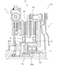
- the clutch device 102 is a device for transmitting power from the engine to the first input shaft 91 and the second input shaft 92 of the transmission, and includes the input rotating body 10 and the first pressure.
- a plate 39, a second pressure plate 49, a first clutch disk assembly 5, a second clutch disk assembly 6, a drive mechanism 7, a rotation support mechanism 11, and a support mechanism 13 are provided.
- the input rotating body 10, the first pressure plate 39, the first clutch disk assembly 5, and the first drive mechanism 7 ⁇ / b> A of the drive mechanism 7 constitute a first clutch C ⁇ b> 1.
- the input clutch 10, the second pressure plate 49, the second clutch disk assembly 6, and the second drive mechanism 7 B of the drive mechanism 7 constitute a second clutch C 2.
- the first clutch C1 and the second clutch C2 are so-called normal open type clutches.
- the first clutch C1 transmits power at the first speed, the third speed, and the fifth speed
- the second clutch C2 transmits power at the second speed and the fourth speed.
- the same number is used about the same member as a 1st embodiment.
- the first input shaft 91 is formed with a step portion 91a, an annular groove 91b, and a spline shaft 91c.
- the spline shaft 91 c is formed in the axial direction on the outer peripheral surface on the distal end side of the first input shaft 91.
- the step portion 91a is formed on the outer periphery of the spline shaft 91c on the transmission side of the spline shaft 91c.
- the annular groove 91 b is formed on the outer periphery on the distal end side of the first input shaft 91.
- the annular groove 91b is formed on the outer periphery of the spline shaft 91c on the engine side of the spline shaft 91c.
- a spline shaft 92 b is formed on the outer peripheral surface on the distal end side of the second input shaft 92.
- An annular groove 92 a is formed on the outer peripheral surface of the second input shaft 92.
- the groove 92a is formed on the outer peripheral surface of the spline shaft 92b on the engine side.
- a stepped portion 92 c is formed on the outer peripheral surface of the second input shaft 92.
- the stepped portion 92c is formed on the outer peripheral surface of the spline shaft 92b on the transmission side.
- the second input shaft 92 is formed so that the diameter of the second input shaft 92 is larger than the diameter of the first input shaft 91.
- the input rotator 10 is a member to which power is transmitted from the engine, and is connected to the crankshaft 99.
- a bearing 34 is fixed to the inner peripheral portion of the crankshaft 99, and the tip of the first input shaft 91 is rotatably supported by the crankshaft 99 by the bearing 34.
- the input rotator 10 mainly includes a first flywheel 3 (first disc portion), a second flywheel 4 (second disc portion), a damper mechanism 15 and an intermediate plate (not shown). Have.
- the intermediate plate is sandwiched between the first flywheel 3 and the second flywheel 4 and can rotate integrally with the first flywheel 3 and the second flywheel 4.
- the first flywheel 3 is connected to the damper mechanism 15 via a connecting member (not shown).
- the damper mechanism 15 is a mechanism for absorbing rotational fluctuations on the engine side, for example, torque fluctuations.
- the damper mechanism 15 is mounted on the outer periphery of the first flywheel 3 so as to be integrally rotatable via a bolt (not shown).
- the damper mechanism 15 includes a torque input member 15a, a plurality of springs 55, and a torque output member 15b.
- the torque input member 15a is a member to which torque is transmitted from the engine side.
- the inner peripheral portion of the torque input member 15a is fixed to the crankshaft 99 with bolts. Further, the torque input member 15a and the torque output member 15b hold the springs 55 at predetermined intervals in the rotation direction.
- the spring 55 is supported between the torque input member 15a and the torque output member 15b so as to be elastically deformable.
- the torque output member 15b is connected to the first flywheel 3 via a bolt (not shown).
- a bearing 34 is fixed to the inner peripheral portion of the crankshaft 99 to which the torque input member 15a is fixed, and the tip of the first input shaft 91 is rotatably supported by the bearing 34 with respect to the crankshaft 99.
- the first pressure plate 39 is disposed in the input rotator 10 and is disposed so as to be able to rotate integrally with the first flywheel 3 and move in the axial direction.
- the first pressure plate 39 is disposed so as to face the first flywheel 3 in the axial direction.
- the first pressure plate 39 is formed with a first support portion 39a protruding outward in the radial direction.
- the 1st support part 39a is arrange
- the first pressure plate 39 is connected to the first drive support member 78 of the first drive mechanism 7A.
- Second Pressure Plate The second pressure plate 49 is disposed in the input rotary body 10 and is disposed so as to be capable of rotating integrally with the second flywheel 4 and moving in the axial direction.
- the second pressure plate 49 is disposed so as to face the second flywheel 4 in the axial direction.
- the second pressure plate 49 is formed with a second support portion 49a that protrudes radially outward.
- the second support portions 49a are arranged at a predetermined interval in the circumferential direction.
- the second pressure plate 49 is connected to the second drive support member 79 of the second drive mechanism 7B.
- the first clutch disk assembly 5 is an assembly for transmitting power from the input rotating body 10 to the first input shaft 91, and supports a support mechanism 13, which will be described later, such as a first support member 35. Connected to the first input shaft 91.
- the first clutch disk assembly 5 includes a first friction part 57, a first input member 52, and a first hub 51.
- the first friction portion 57 is disposed between the first flywheel 3 and the first pressure plate 39 in the axial direction.
- the first friction part 57 is slidably provided on the input rotating body 10 and the first pressure plate 39.
- the first input member 52 is a member to which power is transmitted from the first friction part 57, and is connected to the first friction part 57.
- the first hub 51 supports the first friction part 57 via the first input member 52.
- the first hub 51 is connected to the first input shaft 91 via the first support member 35.
- a spline groove is formed on the inner peripheral surface of the first hub 51.
- Second Clutch Disc Assembly The second clutch disc assembly 6 is an assembly for transmitting power from the input rotating body 10 to the second input shaft 92.
- the second clutch disk assembly 6 includes a second friction portion 67, a second input member 62, a second hub 61, and the shaft movement restriction mechanism 12.
- the second friction portion 67 is disposed between the second flywheel 4 and the second pressure plate 49 in the axial direction.
- the second friction part 67 is slidably provided on the input rotating body 10 and the second pressure plate 49.
- the second input member 62 is a member to which power is transmitted from the second friction portion 67 and is connected to the second friction portion 67.
- the second hub 61 supports the second friction part 67 via the second input member 62.
- the second hub 61 is connected to the second input shaft 92 via the shaft movement restriction mechanism 12.
- a spline groove is formed on the inner peripheral surface of the second hub 61.
- the shaft movement restricting mechanism 12 is provided so as not to rotate with respect to the second input shaft 92, and restricts shaft movement of the rotation support mechanism 11 described later to the engine side.
- the shaft movement restricting mechanism 12 is disposed between the second input shaft 92 and the rotation support mechanism 11, a second support member 45 that supports the rotation support mechanism 11, and shaft movement of the second support member 45 to the engine side.
- the second support member 45 is disposed between the second input shaft 92 and the rotation support mechanism 11 and supports the rotation support mechanism 11.
- the second support member 45 is disposed between the second input shaft 92 and the second hub 61.
- the shaft movement restricting member, for example, the snap ring 46 for the second input shaft restricts the shaft movement of the second support member 45 to the engine side.
- the second support member 45 includes a mechanism support portion 45h that supports the rotation support mechanism 11 and a second hub 61 that is formed integrally with the mechanism support portion 45h and extends radially outward from the mechanism support portion 45h. And a second hub support portion 45i for supporting.
- the mechanism support portion 45 h supports the lower portion of the rotation support mechanism 11, and the second hub support portion 45 i supports the engine-side side portion of the rotation support mechanism 11.
- a spline groove is formed on the inner peripheral surface of the mechanism support portion 45h, and a spline shaft is formed on the outer peripheral portion of the second hub support portion 45i.
- the second support member 45 is attached to the second input shaft 92 by fitting the spline groove of the mechanism support portion 45 h to a spline shaft 92 b formed on the outer peripheral portion of the second input shaft 92.
- the second support member 45 is attached to the second hub 61 by fitting the spline shaft of the second hub support portion 45 i into the spline groove of the second hub 61.
- Drive mechanism The drive mechanism 7 includes a first drive mechanism 7A and a second drive mechanism 7B.
- the first drive mechanism 7 ⁇ / b> A is a mechanism for operating power transmission of the first clutch C ⁇ b> 1, and transmits an axial pressing force to the first pressure plate 39.
- the first drive mechanism 7A includes a first drive support member 78 supported by the input rotator 10 and a first drive support member 78 that moves toward the first flywheel 3 with respect to the input rotator 10.
- the first driving force transmitting portion 71 that transmits the driving force to the driving support member 78 is provided.
- the second drive mechanism 7 ⁇ / b> B is a mechanism for operating the power transmission of the second clutch C ⁇ b> 2 and transmits an axial pressing force to the second pressure plate 49.
- the second drive mechanism 7B includes a second drive support member 79 supported by the input rotator 10, and a second drive mechanism 79 so that the second drive support member 79 moves toward the second flywheel 4 with respect to the input rotator 10.
- the rotation support mechanism 11 is provided between the 2nd input shaft 92 and the input rotary body 10, and supports the input rotary body 10 rotatably with respect to the 2nd input shaft 92. As shown in FIG. Specifically, the rotation support mechanism 11 has a bearing 44. The bearing 44 is disposed between the second flywheel 4 and the second input shaft 92, and supports the second flywheel 4 so as to be rotatable with respect to the second input shaft 92. Specifically, the bearing 44 is disposed between the second flywheel 4 and the mechanism support portion 45 h of the second support member 45 of the shaft movement restriction mechanism 12, and the second flywheel 4 is connected to the second input shaft.
- the support mechanism 13 includes a first support member 35.
- the first support member 35 is mounted on the first input shaft 91, and the first hub support is formed integrally with the mounting portion 35a and extends radially outward from the mounting portion 35a to support the first hub 51.
- the first hub support portion 35b extends radially outward from the axial central portion of the mounting portion 35a.
- a spline groove is formed on the inner peripheral surface of the mounting portion 35a, and a spline shaft is formed on the outer peripheral portion of the first hub support portion 35b. Then, by fitting the spline shaft of the first support member 35 into the spline groove formed in the first hub 51 of the first clutch disk assembly 5, the first support member 35 becomes the first clutch disk assembly. 5 is attached. Further, the first support member 35 cannot rotate with respect to the first input shaft 91 by fitting the spline groove of the first support member 35 to the spline shaft formed on the outer peripheral surface of the first input shaft 91. It is attached to.
- the first support member 35 is attached to the first input shaft 91 by the step 91 a formed on the first input shaft 91 and the snap ring 95 attached to the annular groove 91 b formed on the first input shaft 91.
- ⁇ Assembly of clutch device to input shaft> First, in a state where the clutch device 102 is assembled except for the first support member 35 and the damper mechanism 15, the spline groove of the second support member 45 is fitted into the spline shaft 92 b formed on the outer peripheral surface of the second input shaft 92.
- the transmission-side wall surface of the mechanism support portion 45 h of the second support member 45 abuts on a step portion 92 c formed on the second input shaft 92.
- the second input shaft snap ring 46 which is a shaft movement restricting member, is mounted in an annular groove 92a formed on the outer peripheral surface of the second input shaft 92, whereby the engine of the second support member 45 is engineered. Axial movement to the side is restricted. Thereby, the axial movement to the engine side of the rotation support mechanism 11 is controlled.
- the clutch device 102 including the first support member 35 is positioned by attaching the snap ring 95 for the first input shaft to the annular groove 91 b formed on the outer peripheral surface of the first input shaft 91. Then, by attaching the crankshaft 99 and the damper mechanism 15 to the input rotating body 10, the clutch device 1 is assembled to the input shafts 91 and 92.
- the operation of the clutch device 102 will be described.
- the state shown in FIG. 3 is a state where no pressing force is applied to the first clutch C1 and the second clutch C2 by the drive mechanism 7, and no power is transmitted by the first clutch C1 and the second clutch C2.
- the first pressure plate 39 is connected to the first drive support member 78 of the first drive mechanism 7A, and is disposed to face the first flywheel 3 in the axial direction.
- the second pressure plate 49 is connected to the second drive support member 79 of the second drive mechanism 7B, and is disposed to face the second flywheel 4 in the axial direction.
- the first pressure plate 39, the second pressure plate 49, and the drive mechanism 7 rotate integrally.
- the first input shaft 91 rotatably supports the damper mechanism 15 via the bearing 34. Further, the first input shaft 91 supports the first clutch disk assembly 5 through the first support member 35 so as not to rotate.
- the second input shaft 92 supports the second clutch disk assembly 6 through the second support member 45 in a non-rotatable manner.
- the second support member 45 supports the rotation support mechanism 11 and restricts the movement of the rotation support mechanism 11 toward the engine. Thereby, the rotation of the input rotating body 10 is stabilized.
- the first input shaft 91 side of the transmission is switched to the first speed, and the first drive mechanism 7A is pushed to the engine side by the first actuator (not shown). Then, the first drive support member 78 and the first pressure plate 39 move to the engine side. As a result, the first friction portion 57 of the first clutch disc assembly 5 is sandwiched between the first pressure plate 39 and the first flywheel 3, and the first input shaft 91 is interposed via the first clutch disc assembly 5. Power is transmitted to. By these operations, the vehicle starts to start at the first speed.
- the second input shaft 92 side of the transmission is switched to the second speed.
- the second clutch C2 is switched to the connected state almost simultaneously with the release of the first clutch C1. Specifically, the driving force applied to the first driving mechanism 7A is released. Then, the state of the first drive mechanism 7A returns to the state shown in FIG. 3, and the power transmission via the first clutch C1 is released.
- the first input shaft 91 side of the transmission is switched to the third speed.
- the first clutch C1 is switched to the connected state almost simultaneously with the release of the second clutch C2. Specifically, the driving force applied to the second drive mechanism 7B is released. Then, the state of the second drive mechanism 7B returns to the state shown in FIG. 3, and the power transmission via the second clutch C2 is released.
- the clutch device 102 when traveling at an odd speed, the power is transmitted from the engine to the first input shaft 91 in which an odd number of gears is set. Further, when switching from odd speed to even speed during traveling, even gears are set on the second input shaft 92 in a state where power is transmitted from the engine to the first input shaft 91.
- the second clutch C2 is switched to the connected state almost simultaneously with the release of the first clutch C1
- power is transmitted from the engine to the second input shaft 92 in which an even number of gears is set.
- an odd number of gears is set on the first input shaft 91 in a state where power is transmitted from the engine to the second input shaft 92.
- the first clutch C1 is switched to the connected state almost simultaneously with the release of the second clutch C2
- power is transmitted from the engine to the first input shaft 91 in which an odd number of gears is set.
- the shaft movement of the rotation support mechanism 11 toward the engine is restricted by the shaft movement restriction mechanism 12 included in the second clutch disk assembly 6.
- the shaft movement restricting mechanism 12 is provided so as not to rotate with respect to the second input shaft 92 and restricts the shaft movement of the rotation support mechanism 11 toward the engine.
- the shaft movement restricting mechanism 12 includes a second support member 45 and a shaft movement restricting member such as a snap ring 46 for a second input shaft.
- the second support member 45 supports the rotation support mechanism 11 between the second input shaft 92 and the rotation support mechanism 11.
- the second support member 45 is non-rotatably connected to the second input shaft 92 between the step portion formed on the second input shaft 92 and the snap ring 64 for the second input shaft.
- the axial movement of the second support member 45 toward the engine is restricted. Thereby, the axial movement to the engine side of the rotation support mechanism 11 is controlled.
- the shaft movement to the engine side of the rotation support mechanism 11 with respect to the 2nd input shaft 92 is controlled by the shaft movement control mechanism 12, Therefore Power is transmitted from an engine to a transmission. Thrust force sometimes generated can be transmitted to the second input shaft having a larger diameter than the first input shaft. As described above, in the present clutch device 102, the thrust force generated in the clutch device 102 can be received by the second input shaft 92 having higher rigidity than the first input shaft 91, so that power is stably transmitted from the engine to the transmission. Can be communicated to.
- the present invention is not limited to the above-described embodiment, and various changes and modifications can be made without departing from the gist of the present invention.
- the rotation support mechanism 11 has one bearing 44 is shown, but the number of bearings 44 may be plural.
- the clutch device 103 shown in FIG. 4 includes an input rotator 10, a first pressure plate 39, a second pressure plate 49, a first clutch disk assembly 5, a second clutch disk assembly 6, and a drive.
- a mechanism 7 and a rotation support mechanism 11 are provided.
- the second clutch disk assembly 6 has a shaft movement restricting mechanism 12.
- the rotation support mechanism 11 has two bearings 44.
- the two bearings 44 are disposed between the second flywheel 4 and the second support member 45 of the shaft movement restriction mechanism 12.
- the two bearings 44 are disposed adjacent to each other in the axial direction.
- the first support member 35 has a mounting portion 35a and a first hub support portion 35b.
- the first hub support portion 35 b extends radially outward from the engine side end of the mounting portion 35 a and extends to the transmission side above the rotation support mechanism 11.
- the first hub support portion 35 b supports the second clutch disk assembly 6 above the rotation support mechanism 11.
- the clutch device 104 shown in FIG. 5 includes an input rotator 10, a first pressure plate 39, a second pressure plate 49, a first clutch disk assembly 5, a second clutch disk assembly 6, and a drive.
- a mechanism 7 and a rotation support mechanism 11 are provided.
- the second clutch disk assembly 6 has a shaft movement restricting mechanism 12.
- the rotation support mechanism 11 has a double-row type bearing 44.
- the double row type bearing 44 is disposed between the second flywheel 4 and the second support member 45 of the shaft movement restricting mechanism 12.
- the first support member 35 has a mounting portion 35a and a first hub support portion 35b.
- the first hub support portion 35 b extends radially outward from the engine side end of the mounting portion 35 a and extends to the transmission side above the rotation support mechanism 11.
- the first hub support portion 35 b supports the second clutch disk assembly 6 above the rotation support mechanism 11.
- the input rotator 10 can be supported by two rows of balls, so that the rotation of the input rotator 10 can be stably supported.
- FIGS. 4 and 5 the same reference numerals are used for the same members as in the third embodiment.
- the present invention is applicable to a clutch device for transmitting power from an engine to a transmission having a first input shaft and a second input shaft having a diameter larger than that of the first input shaft.
Landscapes
- Engineering & Computer Science (AREA)
- General Engineering & Computer Science (AREA)
- Mechanical Engineering (AREA)
- Mechanical Operated Clutches (AREA)
Abstract
エンジンからトランスミッションへと動力を安定的に伝達することができるクラッチ装置を、提供することにある。本クラッチ装置(1)は、入力回転体(10)と、第1プレッシャプレート(39)と、第2プレッシャプレート(49)と、第1クラッチディスク組立体(5)と、第2クラッチディスク組立体(6)と、回転支持機構(11)とを備えている。回転支持機構(11)は、第2入力軸(92)と入力回転体(11)との間に設けられており、エンジン側への軸移動が規制されている。この回転支持機構(11)は、入力回転体(10)を第1入力軸(91)および第2入力軸(92)に対して回転可能に支持している。
Description
本発明は、エンジンやモータ等の動力源からトランスミッションへ動力を伝達するためのクラッチ装置に関する。
車両の変速を自動的に行う手段として自動変速機(AT)が知られている。近年のATは、例えばトルクコンバータ、複数の遊星ギアおよびクラッチを組み合わせたものが主流となっている。しかし、ATたとえばトルクコンバータは、流体を介して動力を伝達するので、入力側と出力側とを機械的に直接連結しトルクを伝達する手動変速機(MT)に比べて、動力伝達効率が低下する。したがって、ATは、ドライバーの労力が軽減されるという利点を有している反面、車両の燃費が低下するという欠点を有している。そこで、近年では、MTの伝達効率を確保しつつクラッチ操作を不要とすることを目的とした自動変速機(AMT)が、提案されている(例えば、特許文献1を参照)。この自動変速機では、MTのクラッチ操作およびトランスミッションの変速操作を自動化することができ、従来のMTと同様の伝達効率を確保しつつ、クラッチ操作を不要とすることができる
特許文献1に記載のクラッチ装置は、主に、一対のフライホイールを含むカバー部材、一対のフライホイールの間に配置された一対のプレッシャプレート、およびそれぞれが一対のプレッシャプレートそれぞれによって押圧される一対のクラッチディスクを有している。このようなデュアルタイプのクラッチ装置は、トランスミッションに動力を伝達するための2本のシャフトを介して、エンジンからの動力をトランスミッションへと伝達する。
ここでは、トランスミッションに動力を伝達するための2本のシャフトは、インナーシャフトとアウターシャフトとから構成されている。この場合、クラッチ装置が、主にインナーシャフトに支持された状態において、各シャフトとともに同軸周りに回転することによって、エンジンからの動力をトランスミッションへと伝達する。
このように、従来のデュアルタイプのクラッチ装置は、主にインナーシャフトによって自重が支持されている。この状態において、動力がインナーシャフトへと伝達されると、このインナーシャフトには、自重に加えてスラスト力をも伝達される。しかしながら、インナーシャフトは、構成上、軸径が小さくならざるを得ないので、このインナーシャフトによってクラッチ装置の自重およびスラスト力を支持した状態で、インナーシャフトが回転すると、この回転時に共振等が生じてしまい、エンジンからトランスミッションへの動力の伝達が不安定になってしまうおそれがあった。
本発明は、このような問題を鑑みてなされたものであり、本発明の目的は、エンジンからトランスミッションへと動力を安定的に伝達することができるクラッチ装置を、提供することにある。
請求項1に係るクラッチ装置は、エンジンから、第1入力軸および第1入力軸より大径の第2入力軸を有するトランスミッションへと、動力を伝達するためのクラッチ装置である。
このクラッチ装置は、入力回転体と、第1プレッシャプレートと、第2プレッシャプレートと、第1クラッチディスク組立体と、第2クラッチディスク組立体と、回転支持機構とを備えている。入力回転体は、第1円板部と、第1円板部と空間を隔てて配置された第2円板部とを、有している。第1プレッシャプレートは、入力回転体内に配置され、第1円板部に対して一体回転可能かつ軸方向に移動可能に配置されている。第2プレッシャプレートは、入力回転体内に配置され、第2円板部に対して一体回転可能かつ軸方向に移動可能に配置されている。第1クラッチディスク組立体は、第1円板部と第1プレッシャプレートとの間に配置された第1摩擦部を有しており、第1入力軸に連結されている。第2クラッチディスク組立体は、第2円板部と第2プレッシャプレートとの間に配置された第2摩擦部を有しており、第2入力軸に連結されている。回転支持機構は、第2入力軸と入力回転体との間に設けられており、エンジン側への軸移動が規制されている。この回転支持機構は、入力回転体を第1入力軸および第2入力軸に対して回転可能に支持している。
たとえば、車両を奇数速で発進させる場合、エンジンの動力は、第1プレッシャプレートを第1円板部の方向に移動することによって、第1クラッチディスク組立体を介して、第1円板部から第1入力軸へと伝達される。一方で、車両を偶数速で発進させる場合、エンジンの動力は、第2プレッシャプレートを第2円板部の方向に移動することによって、第2クラッチディスク組立体を介して、第2円板部から第2入力軸へと伝達される。
また、上記のように、エンジンの動力が、第1入力軸および第2入力軸のいずれか一方に伝達される場合には、第1プレッシャプレート又は第2プレッシャプレートを押圧するための反力としてのスラスト力が、発生する。このスラスト力は、エンジン側への軸移動が規制された回転支持機構に入力され、第2入力軸へと伝達される。
このように、本発明では、第2入力軸と入力回転体との間に設けられた回転支持機構のエンジン側への軸移動を規制することによって、エンジンからトランスミッションへと動力を伝達するときに発生するスラスト力を、第1入力軸より大径の第2入力軸に伝達することができる。このように、本発明では、クラッチ装置に発生するスラスト力を、第1入力軸より剛性の高い第2入力軸において受けることができるので、エンジンからトランスミッションへと動力を安定的に伝達することができる。
請求項2に係るクラッチ装置は、請求項1に記載のクラッチ装置において、軸移動規制機構を、さらに備えている。軸移動規制機構は、回転支持機構のエンジン側への軸移動を規制するためのものであり、第2入力軸と回転支持機構との間において第2入力軸に対して回転不能に設けられている。
この場合、第2入力軸と回転支持機構との間に設けられた軸移動規制機構によって、回転支持機構のエンジン側への軸移動が規制されているので、回転支持機構に入力される上記のスラスト力を、第1入力軸より剛性の高い第2入力軸において受けることができる。これにより、エンジンからトランスミッションへと動力を安定的に伝達することができる。
請求項3に係るクラッチ装置では、請求項2に記載のクラッチ装置において、軸移動規制機構は、第2入力軸と回転支持機構との間において回転支持機構を支持する支持部材と、支持部材のエンジン側への軸移動を規制する軸移動規制部材とを有している。
この場合、軸移動規制機構の支持部材によって回転支持機構が支持され、軸移動規制部材によって支持部材のエンジン側への軸移動が規制される。これにより、回転支持機構に入力される上記のスラスト力を、軸移動規制機構を介して、第1入力軸より剛性の高い第2入力軸において受けることができる。これにより、エンジンからトランスミッションへと動力を安定的に伝達することができる。
請求項4に係るクラッチ装置では、請求項1に記載のクラッチ装置において、第2クラッチディスク組立体が、回転支持機構のエンジン側への軸移動を規制する軸移動規制機構を有している。回転支持機構は、軸移動規制機構によって、エンジン側への軸移動が規制される。
この場合、回転支持機構は、第2クラッチディスク組立体が有する軸移動規制機構によって、エンジン側への軸移動が規制されているので、回転支持機構に入力される上記のスラスト力を、第1入力軸より剛性の高い第2入力軸において受けることができる。これにより、エンジンからトランスミッションへと動力を安定的に伝達することができる。
請求項5に係るクラッチ装置では、請求項4に記載のクラッチ装置において、軸移動規制機構が、第2摩擦部を支持し第2入力軸と回転支持機構との間において回転支持機構を支持する支持部材と、支持部材のエンジン側への軸移動を規制する軸移動規制部材とを有している。
この場合、軸移動規制機構の支持部材によって第1摩擦部および回転支持機構が支持され、軸移動規制部材によって支持部材のエンジン側への軸移動が規制される。これにより、回転支持機構に入力される上記のスラスト力を、軸移動規制機構を介して、第1入力軸より剛性の高い第2入力軸において受けることができる。これにより、エンジンからトランスミッションへと動力を安定的に伝達することができる。
本発明では、第2入力軸と入力回転体との間に設けられた回転支持機構のエンジン側への軸移動を規制することによって、エンジンからトランスミッションへと動力を伝達するときに発生するスラスト力を、第1入力軸より大径の第2入力軸に伝達することができる。このように、本発明では、クラッチ装置に発生するスラスト力を、第1入力軸より剛性の高い第2入力軸において受けることができるので、エンジンからトランスミッションへと動力を安定的に伝達することができる。
<クラッチ装置の全体構成>
図1に示すように、本クラッチ装置1は、エンジンから、トランスミッションの第1入力軸91および第2入力軸92に動力を伝達するための装置であって、入力回転体10と、第1プレッシャプレート39と、第2プレッシャプレート49と、第1クラッチディスク組立体5と、第2クラッチディスク組立体6と、駆動機構7と、回転支持機構11と、軸移動規制機構12と、支持機構13とを、備えている。入力回転体10、第1プレッシャプレート39、第1クラッチディスク組立体5、および駆動機構7の第1駆動機構7Aにより、第1クラッチC1が構成されている。入力回転体10、第2プレッシャプレート49、第2クラッチディスク組立体6、および駆動機構7の第2駆動機構7Bにより第2クラッチC2が構成されている。第1クラッチC1および第2クラッチC2は、いわゆるノーマルオープンタイプのクラッチである。第1クラッチC1が第1速、第3速および第5速において動力を伝達し、第2クラッチC2が第2速および第4速において動力を伝達する。
図1に示すように、本クラッチ装置1は、エンジンから、トランスミッションの第1入力軸91および第2入力軸92に動力を伝達するための装置であって、入力回転体10と、第1プレッシャプレート39と、第2プレッシャプレート49と、第1クラッチディスク組立体5と、第2クラッチディスク組立体6と、駆動機構7と、回転支持機構11と、軸移動規制機構12と、支持機構13とを、備えている。入力回転体10、第1プレッシャプレート39、第1クラッチディスク組立体5、および駆動機構7の第1駆動機構7Aにより、第1クラッチC1が構成されている。入力回転体10、第2プレッシャプレート49、第2クラッチディスク組立体6、および駆動機構7の第2駆動機構7Bにより第2クラッチC2が構成されている。第1クラッチC1および第2クラッチC2は、いわゆるノーマルオープンタイプのクラッチである。第1クラッチC1が第1速、第3速および第5速において動力を伝達し、第2クラッチC2が第2速および第4速において動力を伝達する。
第1入力軸91には、段差部91a、環状溝91b、およびスプライン軸91cが、形成されている。スプライン軸91cは、第1入力軸91の先端側の外周面において軸方向に形成されている。段差部91aは、スプライン軸91cのトランスミッション側において、スプライン軸91cの外周に形成されている。環状溝91bは、第1入力軸91の先端側の外周に形成されている。詳細には、環状溝91bは、スプライン軸91cのエンジン側において、スプライン軸91cの外周に形成されている。
第2入力軸92の先端側の外周面には、スプライン軸92bが形成されている。また、第2入力軸92の外周面には、環状の溝部92aが形成されている。さらに、第2入力軸92の径が第1入力軸91の径より大径になるように、第2入力軸92は形成されている。溝部92aを基準としたトランスミッション側の外周面の径が、溝部92aを基準としたエンジン側外周面の径より大きくなるように、第2入力軸92は形成されている。詳細には、第2入力軸92のトランスミッション側の外周面の径が、第2入力軸92のスプライン軸92bの外周面の径より大きくなっている。
・入力回転体
入力回転体10は、エンジンから動力が伝達される部材であり、フレキシブルプレート93を介して、クランクシャフト99に連結されている。フレキシブルプレート93の内周部はボルトによりクランクシャフト99に固定されており、フレキシブルプレート93の外周部はボルト(図示しない)により入力回転体10に固定されている。クランクシャフト99の内周部にはベアリングが固定されており、このベアリングにより第1入力軸91の先端が回転可能に支持されている。
・入力回転体
入力回転体10は、エンジンから動力が伝達される部材であり、フレキシブルプレート93を介して、クランクシャフト99に連結されている。フレキシブルプレート93の内周部はボルトによりクランクシャフト99に固定されており、フレキシブルプレート93の外周部はボルト(図示しない)により入力回転体10に固定されている。クランクシャフト99の内周部にはベアリングが固定されており、このベアリングにより第1入力軸91の先端が回転可能に支持されている。
入力回転体10は、主に、第1フライホイール3(第1円板部)と、第2フライホイール4(第2円板部)と、中間プレート38とを有している。中間プレート38は、第1フライホイール3と第2フライホイール4との間に挟み込まれており、第1フライホイール3および第2フライホイール4と一体回転可能になっている。第1プレッシャプレート39は、図示しない第1ストラッププレートを介して、中間プレート38に一体回転可能にかつ軸方向に弾性的に連結されている。第2プレッシャプレート49は、図示しない第2ストラッププレートを介して、中間プレート38に一体回転可能にかつ軸方向に弾性的に連結されている。
・第1プレッシャプレート
第1プレッシャプレート39は、入力回転体10内に配置されており、第1フライホイール3に対して一体回転可能かつ軸方向に移動可能に配置されている。第1プレッシャプレート39は、第1フライホイール3と軸方向に対向して配置されている。第1プレッシャプレート39には、径方向外方に突出した第1支持部39aが、形成されている。第1支持部39aは、円周方向に、所定の間隔を隔てて配置されている。この第1支持部39aにおいて、第1プレッシャプレート39は、第1駆動機構7Aの第1駆動支持部材78に連結されている。なお、第1プレッシャプレート39には、第1支持部39aとは異なる位置において、円周方向に所定の間隔を隔てて、第1突出部(図示しない)が設けられている。この第1突出部において、第1ストラッププレートは、第1プレッシャプレート39に固定されている。
・第2プレッシャプレート
第2プレッシャプレート49は、入力回転体10内に配置されており、第2フライホイール4に対して一体回転可能かつ軸方向に移動可能に配置されている。第2プレッシャプレート49は、第2フライホイール4と軸方向に対向して配置されている。第2プレッシャプレート49には、径方向外方に突出した第2支持部49aが、形成されている。第2支持部49aは、円周方向に、所定の間隔を隔てて配置されている。この第2支持部49aにおいて、第2プレッシャプレート49は、第2駆動機構7Bの第2駆動支持部材79に連結されている。なお、第2プレッシャプレート49には、第2支持部49aとは異なる位置において、円周方向に所定の間隔を隔てて、第2突出部(図示しない)が設けられている。この第2突出部において、第2ストラッププレートは、第2プレッシャプレート49に固定されている。
・第1クラッチディスク組立体
第1クラッチディスク組立体5は、入力回転体10から第1入力軸91へ動力を伝達するためのアッセンブリであり、後述する支持機構13たとえば第1支持部材35を介して第1入力軸91に連結されている。第1クラッチディスク組立体5は、第1摩擦部57と、第1入力部材52と、第1ハブ51と、複数の第1スプリング55と、を有している。第1摩擦部57は、第1フライホイール3と第1プレッシャプレート39との軸方向間に配置されている。第1摩擦部57は、入力回転体10および第1プレッシャプレート39と摺動可能に設けられている。第1入力部材52は、第1摩擦部57から動力が伝達される部材であり、第1摩擦部57に連結されている。第1ハブ51の内周面には、後述する支持機構13に連結するためのスプライン溝が、形成されている。第1ハブ51は、支持機構13を介して第1入力軸91に連結されている。第1スプリング55は、第1入力部材52により弾性変形可能に支持されており、第1入力部材52と第1ハブ51とを回転方向に弾性的に連結している。
・第2クラッチディスク組立体
第2クラッチディスク組立体6は、入力回転体10から第2入力軸92へ動力を伝達するためのアッセンブリであり、第2入力軸92に連結されている。第2クラッチディスク組立体6は、第2摩擦部67と、第2入力部材62と、第2ハブ61と、複数の第2スプリング65と、を有している。第2摩擦部67は、第2フライホイール4と第2プレッシャプレート49との軸方向間に配置されている。第2摩擦部67は、入力回転体10および第2プレッシャプレート49と摺動可能に設けられている。第2入力部材62は、第2摩擦部67から動力が伝達される部材であり、第2摩擦部67に連結されている。第2ハブ61の内周面には、スプライン溝が形成されており、このスプライン溝によって、第2ハブ61は第2入力軸92に連結されている。第2スプリング65は、第2入力部材62により弾性変形可能に支持されており、第2入力部材62と第2ハブ61とを回転方向に弾性的に連結している。
・駆動機構
駆動機構7は、第1駆動機構7Aおよび第2駆動機構7Bを有している。第1駆動機構7Aは、第1クラッチC1の動力伝達を操作するための機構であって、第1プレッシャプレート39に軸方向の押し付け力を伝達する。第1駆動機構7Aは、入力回転体10に支持された第1駆動支持部材78と、第1駆動支持部材78が入力回転体10に対して第1フライホイール3側に移動するように第1駆動支持部材78に駆動力を伝達する第1駆動力伝達部71とを、有している。第2駆動機構7Bは、第2クラッチC2の動力伝達を操作するための機構であって、第2プレッシャプレート49に軸方向の押し付け力を伝達する。第2駆動機構7Bは、入力回転体10に支持された第2駆動支持部材79と、第2駆動支持部材79が入力回転体10に対して第2フライホイール4側に移動するように第2駆動支持部材79に駆動力を伝達する第2駆動力伝達部72とを、有している。
・回転支持機構
回転支持機構11は、第1回転支持機構211と、第2回転支持機構111とを有している。第1回転支持機構211は、第1入力軸91と入力回転体10との間に設けられており、入力回転体10を第1入力軸91に対して回転可能に支持する。具体的には、第1回転支持機構211は、第1ベアリング34を有している。第1ベアリング34は、第1フライホイール3と第1入力軸91との間に配置されており、第1フライホイール3を第1入力軸91に対して回転可能に支持している。詳細には、第1ベアリング34は、第1フライホイール3と第1支持部材35との間に配置されており、第1フライホイール3を第1入力軸91に対して回転可能に支持している。
・第1プレッシャプレート
第1プレッシャプレート39は、入力回転体10内に配置されており、第1フライホイール3に対して一体回転可能かつ軸方向に移動可能に配置されている。第1プレッシャプレート39は、第1フライホイール3と軸方向に対向して配置されている。第1プレッシャプレート39には、径方向外方に突出した第1支持部39aが、形成されている。第1支持部39aは、円周方向に、所定の間隔を隔てて配置されている。この第1支持部39aにおいて、第1プレッシャプレート39は、第1駆動機構7Aの第1駆動支持部材78に連結されている。なお、第1プレッシャプレート39には、第1支持部39aとは異なる位置において、円周方向に所定の間隔を隔てて、第1突出部(図示しない)が設けられている。この第1突出部において、第1ストラッププレートは、第1プレッシャプレート39に固定されている。
・第2プレッシャプレート
第2プレッシャプレート49は、入力回転体10内に配置されており、第2フライホイール4に対して一体回転可能かつ軸方向に移動可能に配置されている。第2プレッシャプレート49は、第2フライホイール4と軸方向に対向して配置されている。第2プレッシャプレート49には、径方向外方に突出した第2支持部49aが、形成されている。第2支持部49aは、円周方向に、所定の間隔を隔てて配置されている。この第2支持部49aにおいて、第2プレッシャプレート49は、第2駆動機構7Bの第2駆動支持部材79に連結されている。なお、第2プレッシャプレート49には、第2支持部49aとは異なる位置において、円周方向に所定の間隔を隔てて、第2突出部(図示しない)が設けられている。この第2突出部において、第2ストラッププレートは、第2プレッシャプレート49に固定されている。
・第1クラッチディスク組立体
第1クラッチディスク組立体5は、入力回転体10から第1入力軸91へ動力を伝達するためのアッセンブリであり、後述する支持機構13たとえば第1支持部材35を介して第1入力軸91に連結されている。第1クラッチディスク組立体5は、第1摩擦部57と、第1入力部材52と、第1ハブ51と、複数の第1スプリング55と、を有している。第1摩擦部57は、第1フライホイール3と第1プレッシャプレート39との軸方向間に配置されている。第1摩擦部57は、入力回転体10および第1プレッシャプレート39と摺動可能に設けられている。第1入力部材52は、第1摩擦部57から動力が伝達される部材であり、第1摩擦部57に連結されている。第1ハブ51の内周面には、後述する支持機構13に連結するためのスプライン溝が、形成されている。第1ハブ51は、支持機構13を介して第1入力軸91に連結されている。第1スプリング55は、第1入力部材52により弾性変形可能に支持されており、第1入力部材52と第1ハブ51とを回転方向に弾性的に連結している。
・第2クラッチディスク組立体
第2クラッチディスク組立体6は、入力回転体10から第2入力軸92へ動力を伝達するためのアッセンブリであり、第2入力軸92に連結されている。第2クラッチディスク組立体6は、第2摩擦部67と、第2入力部材62と、第2ハブ61と、複数の第2スプリング65と、を有している。第2摩擦部67は、第2フライホイール4と第2プレッシャプレート49との軸方向間に配置されている。第2摩擦部67は、入力回転体10および第2プレッシャプレート49と摺動可能に設けられている。第2入力部材62は、第2摩擦部67から動力が伝達される部材であり、第2摩擦部67に連結されている。第2ハブ61の内周面には、スプライン溝が形成されており、このスプライン溝によって、第2ハブ61は第2入力軸92に連結されている。第2スプリング65は、第2入力部材62により弾性変形可能に支持されており、第2入力部材62と第2ハブ61とを回転方向に弾性的に連結している。
・駆動機構
駆動機構7は、第1駆動機構7Aおよび第2駆動機構7Bを有している。第1駆動機構7Aは、第1クラッチC1の動力伝達を操作するための機構であって、第1プレッシャプレート39に軸方向の押し付け力を伝達する。第1駆動機構7Aは、入力回転体10に支持された第1駆動支持部材78と、第1駆動支持部材78が入力回転体10に対して第1フライホイール3側に移動するように第1駆動支持部材78に駆動力を伝達する第1駆動力伝達部71とを、有している。第2駆動機構7Bは、第2クラッチC2の動力伝達を操作するための機構であって、第2プレッシャプレート49に軸方向の押し付け力を伝達する。第2駆動機構7Bは、入力回転体10に支持された第2駆動支持部材79と、第2駆動支持部材79が入力回転体10に対して第2フライホイール4側に移動するように第2駆動支持部材79に駆動力を伝達する第2駆動力伝達部72とを、有している。
・回転支持機構
回転支持機構11は、第1回転支持機構211と、第2回転支持機構111とを有している。第1回転支持機構211は、第1入力軸91と入力回転体10との間に設けられており、入力回転体10を第1入力軸91に対して回転可能に支持する。具体的には、第1回転支持機構211は、第1ベアリング34を有している。第1ベアリング34は、第1フライホイール3と第1入力軸91との間に配置されており、第1フライホイール3を第1入力軸91に対して回転可能に支持している。詳細には、第1ベアリング34は、第1フライホイール3と第1支持部材35との間に配置されており、第1フライホイール3を第1入力軸91に対して回転可能に支持している。
第2回転支持機構111は、第2入力軸92と入力回転体10との間に設けられており、入力回転体10を第2入力軸92に対して回転可能に支持する。具体的には、第2回転支持機構111は、第2ベアリング44を有している。第2ベアリング44は、第2フライホイール4と第2入力軸92との間に配置されており、第2フライホイール4を第2入力軸92に対して回転可能に支持している。詳細には、第2ベアリング44は、第2フライホイール4と、後述する軸移動規制機構12との間に配置されており、第2フライホイール4を第2入力軸92に対して回転可能に支持している。また、第2ベアリング44は、軸方向に対向する一対のスナップリング20,21によって、第2フライホイール4と、後述する軸移動規制機構12とに対して、軸方向に移動不能に装着されている。
・軸移動規制機構
軸移動規制機構12は、第2入力軸92と、回転支持機構11すなわち第2回転支持機構111との間において第2入力軸92に対して回転不能に設けられ、第2回転支持機構111のエンジン側への軸移動を規制する。軸移動規制機構12は、第2支持部材45と、軸移動規制部材46とを有している。第2支持部材45は、第2入力軸92と第2回転支持機構111との間において、第2回転支持機構111を支持している。軸移動規制部材たとえば第2入力軸用のスナップリング46は、第2支持部材45のエンジン側への軸移動を規制している。
・軸移動規制機構
軸移動規制機構12は、第2入力軸92と、回転支持機構11すなわち第2回転支持機構111との間において第2入力軸92に対して回転不能に設けられ、第2回転支持機構111のエンジン側への軸移動を規制する。軸移動規制機構12は、第2支持部材45と、軸移動規制部材46とを有している。第2支持部材45は、第2入力軸92と第2回転支持機構111との間において、第2回転支持機構111を支持している。軸移動規制部材たとえば第2入力軸用のスナップリング46は、第2支持部材45のエンジン側への軸移動を規制している。
具体的には、第2支持部材45は、筒状に形成されている。第2支持部材45の外周面には、エンジン側において径方向外方に突出し第2ベアリング44を支持する突出部45aと、トランスミッション側において第2ベアリング44を支持するスナップリングを嵌合するための環状溝45bとを有している。また、第2支持部材45の内周面には、第2入力軸用のスナップリング46が待機する待機凹部45cと、第2入力軸用のスナップリング46を係止する係止凹部45dと、第2入力軸用のスナップリング46を回収する回収凹部45eとを有している。第2支持部材45の内周面には、軸方向にスプライン溝が形成されている。
係止凹部45dの底部の内径が、待機凹部45cの底部の内径より小さくなるように、係止凹部45dは形成されている。また、係止凹部45dの底部の内径が、回収凹部45eの底部の内径より小さくなるように、係止凹部45dは形成されている。
なお、自由時のスナップリング46(第2入力軸92に装着前のスナップリング46)の外径が回収凹部45eの外径より大きくなるように、スナップリング46は形成されている。また、自由時のスナップリング46の内径が第2入力軸92のスプライン92bの外径より大きくなるように、スナップリング46は形成されている。さらに、スナップリング46の外径と内径との差が回収凹部45eのエンジン側の壁部の高さより小さくなるように、スナップリング46は形成されている。このようにスナップリング46を形成することによって、スナップリング46を回収凹部45eに確実に回収することができる。
・支持機構
支持機構13は、第1支持部材35を有している。第1支持部材35は、筒状に形成されており、内周面にはスプライン溝が形成されている。そして、第1支持部材35のスプライン溝を、第1入力軸91の外周面に形成されたスプライン軸91cに嵌合することによって、第1支持部材35は、第1入力軸91に対して回転不能に装着される。また、第1支持部材35の外周面には、スプライン軸が形成されている。そして、第1支持部材35のスプライン軸を、第1クラッチディスク組立体5の第1ハブ51に形成されたスプライン溝に嵌合することによって、第1支持部材35が、第1クラッチディスク組立体5に装着される。また、第1入力軸91に形成された段差部91aと、第1入力軸91に形成された環状溝91bに装着されるスナップリング95とによって、第1支持部材35が第1入力軸91に位置決めされる。
・支持機構
支持機構13は、第1支持部材35を有している。第1支持部材35は、筒状に形成されており、内周面にはスプライン溝が形成されている。そして、第1支持部材35のスプライン溝を、第1入力軸91の外周面に形成されたスプライン軸91cに嵌合することによって、第1支持部材35は、第1入力軸91に対して回転不能に装着される。また、第1支持部材35の外周面には、スプライン軸が形成されている。そして、第1支持部材35のスプライン軸を、第1クラッチディスク組立体5の第1ハブ51に形成されたスプライン溝に嵌合することによって、第1支持部材35が、第1クラッチディスク組立体5に装着される。また、第1入力軸91に形成された段差部91aと、第1入力軸91に形成された環状溝91bに装着されるスナップリング95とによって、第1支持部材35が第1入力軸91に位置決めされる。
<クラッチ装置の入力軸への組み付け及び取り外し>
まず、支持機構13を除くクラッチ装置1を組み立てた状態において、第2入力軸用のスナップリング46を、第2支持部材45の待機凹部45cと第2入力軸92のエンジン側先端部外周との間に配置する。
まず、支持機構13を除くクラッチ装置1を組み立てた状態において、第2入力軸用のスナップリング46を、第2支持部材45の待機凹部45cと第2入力軸92のエンジン側先端部外周との間に配置する。
続いて、クラッチ装置1をスプラインに沿ってトランスミッション側へと移動すると、環状突起45kのスプライン溝が、第2入力軸92のスプライン軸92bに嵌合する。そして、クラッチ装置1をスプラインに沿ってトランスミッション側へとさらに移動すると、待機凹部45cに配置されたスナップリング46が、第2入力軸92の溝部92aに到着する。すると、このスナップリング46は、第2入力軸92の溝部92aのトランスミッション側の壁面に当接する。このようにして、スナップリング46のトランスミッション側への移動が、第2入力軸92の溝部92aにより規制される。ここでは、第2入力軸92のトランスミッション側の外周面の径(溝部92aを基準としたトランスミッション側の外周面の径)が、第2入力軸92のスプライン軸92bの外周面の径(溝部92aを基準としたエンジン側外周面の径)より大きくなっているので、スナップリング46のトランスミッション側への移動を、第2入力軸92の溝部92aのトランスミッション側の壁部により規制することができる。なお、この状態では、スナップリング46の内周面と、第2入力軸92の溝部92aの底部との間には、隙間が設けられている。
そして、クラッチ装置1をスプラインに沿ってトランスミッション側へとさらに移動すると、スナップリング46が、待機凹部45cに嵌合された状態すなわち待機凹部45のエンジン側の壁面に当接した状態において、待機凹部45cのエンジン側のテーパ状の壁部において、待機凹部45cから係止凹部45dへと縮径しながら案内され、第2入力軸92の溝部92aに嵌合される。そして、スナップリング46が係止凹部45dに到達すると、スナップリング46は拡径し係止凹部45dに嵌合される。このようにして、スナップリング46は、第2入力軸92の溝部92aと係止凹部45dとに係合し、第2支持部材45のエンジン側への軸移動を規制する。
なお、第2入力軸92のスプライン軸92bは、第2入力軸92の先端部と溝部92aとの間に形成されている。詳細には、スプライン軸92bは、第2入力軸92の外周面においてエンジン側の先端部からトランスミッション側へと延び、溝部92aに到達する手前すなわち概ね溝部92aのエンジン側に、終端を有している。
続いて、支持機構13たとえば第1支持部材35が、第1入力軸91と、第1クラッチディスク組立体5および第1フライホイール3に装着された第1回転支持機構211との間に装着される。たとえば、第1支持部材35の内周面のスプライン溝が、第1入力軸91のスプライン軸に嵌合され、第1支持部材35の外周面のスプライン軸が、第1クラッチディスク組立体5のスプライン溝に嵌合される。そして、クラッチ装置1をスプラインに沿ってトランスミッション側へ移動する。そして、第1支持部材35が、第1入力軸91の段差部91aに当接すると、スナップリング95が第1入力軸91の環状溝91bに装着される。これにより、第1支持部材35が、第1入力軸91に位置決めされる。このようにして、クラッチ装置1は、入力軸91,92に装着される。
次に、クラッチ装置1が入力軸91,92に装着された状態において、第1支持部材35を第1入力軸91に位置決めするためのスナップリング95が、取り外される。そして、取り外し治具(図示しない)がボルトを介して第1支持部材35に装着され、取り外し治具をエンジン側へと移動することによって、第1支持部材35が、第1入力軸91から取り外される。この状態で、クラッチ装置1をスプラインに沿ってトランスミッション側へと移動させると、スナップリング46が、係止凹部45dに嵌合された状態すなわち係止凹部45dのエンジン側のテーパ状の壁部に当接した状態おいて、係止凹部45dから回収凹部45eへと再び縮径しながら案内される。そして、スナップリング46が回収凹部45eに到達すると、スナップリング46は拡径し、回収凹部45eに回収される。続いて、今度は、クラッチ装置1を、スプラインに沿ってエンジン側へと移動すると、スナップリング46が第2支持部材45の回収凹部45eに回収された状態で、第1支持部材35が取り外されたクラッチ装置1が、入力軸91,92から取り外される。
<本クラッチ装置の動作>
クラッチ装置1の動作について説明する。図1に示す状態は、駆動機構7により第1クラッチC1および第2クラッチC2に押付力が付与されていない状態であり、第1クラッチC1および第2クラッチC2で動力伝達が行われていない状態である。この状態では、第1プレッシャプレート39は、図1に示す軸方向位置に保持されており、第2プレッシャプレート49も、図1に示す軸方向位置に保持されている。ここで、エンジンから動力が入力回転体10に伝達されると、入力回転体10、第1プレッシャプレート39、第2プレッシャプレート49および駆動機構7は一体回転する。第1入力軸91が支持部材35を介して第1ベアリング34を支持しており、第1ベアリング34が第1フライホイール3を回転可能に支持している。また、第2入力軸92が軸移動規制機構12を介して第2ベアリング44を支持しており、第2ベアリング44が第2フライホイール4を回転可能に支持している。これにより、入力回転体10の回転が安定する。
クラッチ装置1の動作について説明する。図1に示す状態は、駆動機構7により第1クラッチC1および第2クラッチC2に押付力が付与されていない状態であり、第1クラッチC1および第2クラッチC2で動力伝達が行われていない状態である。この状態では、第1プレッシャプレート39は、図1に示す軸方向位置に保持されており、第2プレッシャプレート49も、図1に示す軸方向位置に保持されている。ここで、エンジンから動力が入力回転体10に伝達されると、入力回転体10、第1プレッシャプレート39、第2プレッシャプレート49および駆動機構7は一体回転する。第1入力軸91が支持部材35を介して第1ベアリング34を支持しており、第1ベアリング34が第1フライホイール3を回転可能に支持している。また、第2入力軸92が軸移動規制機構12を介して第2ベアリング44を支持しており、第2ベアリング44が第2フライホイール4を回転可能に支持している。これにより、入力回転体10の回転が安定する。
例えば、車両が第1速で発進する際、トランスミッションの第1入力軸91側が第1速に切り替えられ、第1駆動機構7Aが第1アクチュエータ(図示せず)によりエンジン側に押される。すると、第1駆動支持部材78および第1プレッシャプレート39がエンジン側に移動する。この結果、第1クラッチディスク組立体5の第1摩擦部57が第1プレッシャプレート39と第1フライホイール3との間に挟み込まれ、第1クラッチディスク組立体5を介して第1入力軸91に動力が伝達される。これらの動作により、車両は第1速で発進を開始する。
第1速から第2速への変速時には、トランスミッションの第2入力軸92側が第2速に切り替えられる。トランスミッションが第2速の状態で、第1クラッチC1の解除とほぼ同時に第2クラッチC2が連結状態に切り替えられる。具体的には、第1駆動機構7Aに付与されている駆動力が解放される。すると、第1駆動機構7Aの状態が図1に示す状態に戻り、第1クラッチC1を介した動力伝達が解除される。
一方で、第2駆動機構7Bが第2アクチュエータ(図示せず)によりエンジン側に押されると、第2駆動支持部材79および第2プレッシャプレート49がトランスミッション側に移動する。この結果、第2クラッチディスク組立体6の第2摩擦部67が第2プレッシャプレート49と第2フライホイール4との間に挟み込まれ、第2クラッチディスク組立体6を介して第2入力軸92に動力が伝達される。これらの動作により、変速段が第1速から第2速に切り替えら、車両は第2速で走行を開始する。
第2速から第3速への変速時には、トランスミッションの第1入力軸91側が第3速に切り替えられる。トランスミッションが第3速の状態で、第2クラッチC2の解除とほぼ同時に第1クラッチC1が連結状態に切り替えられる。具体的には、第2駆動機構7Bに付与されている駆動力が解放される。すると、第2駆動機構7Bの状態が図1に示す状態に戻り、第2クラッチC2を介した動力伝達が解除される。
上記の内容をまとめると、本クラッチ装置1では、奇数速での走行時には、動力は、エンジンから、奇数のギアがセットされた第1入力軸91へと伝達される。また、走行時に奇数速から偶数速へと切り換えられる場合、動力がエンジンから第1入力軸91へと伝達されている状態において、偶数のギアが第2入力軸92にセットされる。そして、第1クラッチC1の解除とほぼ同時に、第2クラッチC2が連結状態に切り替えられると、動力が、エンジンから、偶数のギアがセットされた第2入力軸92へと伝達される。さらに、走行時に偶数速から奇数速へと切り換えられる場合、動力がエンジンから第2入力軸92へと伝達されている状態において、奇数のギアが第1入力軸91にセットされる。そして、第2クラッチC2の解除とほぼ同時に、第1クラッチC1が連結状態に切り替えられると、動力が、エンジンから、奇数のギアがセットされた第1入力軸91へと伝達される。
<本クラッチ装置の特徴>
以下に、クラッチ装置1の特徴を示す。
以下に、クラッチ装置1の特徴を示す。
図1に示したように、本クラッチ装置1では、回転支持機構11すなわち第2回転支持機構111のエンジン側への軸移動が、軸移動規制機構12によって規制されている。軸移動規制機構12は、第2支持部材45と、第2入力軸用のスナップリング46とを有している。第2支持部材45は、第2入力軸92と第2回転支持機構111との間において、第2回転支持機構111を支持している。そして、第2入力軸用のスナップリング46を、第2支持部材45と第2入力軸92とに係合することによって、第2支持部材45のエンジン側への軸移動が規制されている。このようにして、軸移動規制機構12は、第2入力軸92と第2回転支持機構111との間において、第2回転支持機構111のエンジン側への軸移動を規制している。
このように、本クラッチ装置1では、第2入力軸92に対する第2回転支持機構111のエンジン側への軸移動が、軸移動規制機構12によって規制されているので、エンジンからトランスミッションへと動力を伝達するときに発生するスラスト力を、第1入力軸91より大径の第2入力軸92に伝達することができる。このように、本クラッチ装置1では、クラッチ装置1に発生するスラスト力を、第1入力軸91より剛性の高い第2入力軸92において受けることができるので、エンジンからトランスミッションへと動力を安定的に伝達することができる。
<クラッチ装置の全体構成>
図2に示すように、本クラッチ装置101は、エンジンから、トランスミッションの第1入力軸91および第2入力軸92に動力を伝達するための装置であって、入力回転体10と、第1プレッシャプレート39と、第2プレッシャプレート49と、第1クラッチディスク組立体5と、第2クラッチディスク組立体6と、駆動機構7と、回転支持機構11と、軸移動規制機構12と、支持機構13とを、備えている。
図2に示すように、本クラッチ装置101は、エンジンから、トランスミッションの第1入力軸91および第2入力軸92に動力を伝達するための装置であって、入力回転体10と、第1プレッシャプレート39と、第2プレッシャプレート49と、第1クラッチディスク組立体5と、第2クラッチディスク組立体6と、駆動機構7と、回転支持機構11と、軸移動規制機構12と、支持機構13とを、備えている。
図2に示したクラッチ装置101の構成は、軸移動規制機構12の部分を除くと、基本的には、第1実施形態に示したクラッチ装置1と同じである。このため、ここでは、第1実施形態に示したクラッチ装置101と構成が同じ部分についての説明は、省略する。また、第1実施形態と同じ部材については、同じ番号を用いている。
・軸移動規制機構
軸移動規制機構12は、第2入力軸92と、回転支持機構11すなわち第2回転支持機構111との間において第2入力軸92に対して回転不能に設けられ、第2回転支持機構111のエンジン側への軸移動を規制する。軸移動規制機構12は、第2支持部材45と、軸移動規制部材46と、補助部材47とを有している。第2支持部材45は、第2入力軸92と第2回転支持機構111との間において、第2回転支持機構111を支持している。軸移動規制部材たとえば第2入力軸用のスナップリング46は、第2支持部材45のエンジン側への軸移動を規制している。補助部材たとえば補助リング47は、第2支持部材45を第2入力軸92から取り外すために用いる部材である。
・軸移動規制機構
軸移動規制機構12は、第2入力軸92と、回転支持機構11すなわち第2回転支持機構111との間において第2入力軸92に対して回転不能に設けられ、第2回転支持機構111のエンジン側への軸移動を規制する。軸移動規制機構12は、第2支持部材45と、軸移動規制部材46と、補助部材47とを有している。第2支持部材45は、第2入力軸92と第2回転支持機構111との間において、第2回転支持機構111を支持している。軸移動規制部材たとえば第2入力軸用のスナップリング46は、第2支持部材45のエンジン側への軸移動を規制している。補助部材たとえば補助リング47は、第2支持部材45を第2入力軸92から取り外すために用いる部材である。
具体的には、第2支持部材45は、筒状に形成されている。第2支持部材45の外周面には、エンジン側において径方向外方に突出し第2ベアリング44を支持する突出部45aと、トランスミッション側において第2ベアリング44を支持するスナップリングを嵌合するための環状溝45bとを有している。また、第2支持部材45の内周面には、第2入力軸用のスナップリング46が待機する第1待機凹部45fと、補助リング47が待機する第2待機凹部45gとを有している。第2支持部材45の内周面には、スプライン溝が形成されている。
スナップリング46は第1待機凹部45fに待機しているときには、スナップリング46が拡径された状態で、スナップリング46の内周面が、第2入力軸92の外周面に嵌合されている。そして、第1待機凹部45fに待機するスナップリング46が縮径し、第2入力軸92の溝部92aに嵌合されると、スナップリング46は、第1待機凹部45fと溝部92aとの間に配置される。
補助リング47は第2待機凹部45gに待機しているときには、補助リング47が拡径された状態で、補助リング47の内周面が、第2入力軸92の外周面に嵌合されている。そして、第2待機凹部45gに待機する補助リング47が縮径し、第2入力軸92の溝部92aに嵌合されると、補助リング47の外周面は、第2入力軸92の外周面と同一面を形成する。言い換えると、補助リング47は、外周面が第2入力軸92の外周面と同一面となるように、第2入力軸92に形成された環状の溝部92aに嵌合される。
<クラッチ装置の入力軸への組み付け及び取り外し>
まず、支持機構13を除くクラッチ装置101を組み立てた状態において、第2入力軸用のスナップリング46を、第2支持部材45の第1待機凹部45fと第2入力軸92のエンジン側先端部外周との間に配置する。また、補助リング47を、第2支持部材45の第2待機凹部45gと第2入力軸92のエンジン側先端部外周との間に配置する。この状態では、第2入力軸92の外周面に形成されたスプライン軸92bと、第2支持部材45のスプライン溝とが、嵌合されている。続いて、クラッチ装置101をスプラインに沿ってトランスミッション側へと移動し、第1待機凹部45fのスナップリング46が、第2入力軸92の溝部92aに到着すると、このスナップリング46は縮径し第2入力軸92の溝部92aに嵌合される。すると、スナップリング46が、第1待機凹部45fと第2入力軸92の溝部92aとに係合し、第2支持部材45のエンジン側への軸移動が、規制される。
<クラッチ装置の入力軸への組み付け及び取り外し>
まず、支持機構13を除くクラッチ装置101を組み立てた状態において、第2入力軸用のスナップリング46を、第2支持部材45の第1待機凹部45fと第2入力軸92のエンジン側先端部外周との間に配置する。また、補助リング47を、第2支持部材45の第2待機凹部45gと第2入力軸92のエンジン側先端部外周との間に配置する。この状態では、第2入力軸92の外周面に形成されたスプライン軸92bと、第2支持部材45のスプライン溝とが、嵌合されている。続いて、クラッチ装置101をスプラインに沿ってトランスミッション側へと移動し、第1待機凹部45fのスナップリング46が、第2入力軸92の溝部92aに到着すると、このスナップリング46は縮径し第2入力軸92の溝部92aに嵌合される。すると、スナップリング46が、第1待機凹部45fと第2入力軸92の溝部92aとに係合し、第2支持部材45のエンジン側への軸移動が、規制される。
なお、第2入力軸92のスプライン軸92bは、第2入力軸92の先端部と溝部92aとの間に形成されている。詳細には、スプライン軸92bは、第2入力軸92の外周面においてエンジン側の先端部からトランスミッション側へと延び、溝部92aに到達する手前すなわち概ね溝部92aのエンジン側に、終端を有している。
続いて、支持機構13たとえば第1支持部材35が、第1入力軸91と、第1クラッチディスク組立体5および第1フライホイール3に装着された第1回転支持機構211との間に装着される。たとえば、第1支持部材35の内周面のスプライン溝が、第1入力軸91のスプライン軸に嵌合され、第1支持部材35の外周面のスプライン軸が、第1クラッチディスク組立体5のスプライン溝に嵌合される。そして、クラッチ装置101をスプラインに沿ってトランスミッション側へ移動する。そして、第1支持部材35が、第1入力軸91の段差部91aに当接すると、スナップリング95が第1入力軸91の環状溝91bに装着される。これにより、第1支持部材35が、第1入力軸91に位置決めされる。このようにして、クラッチ装置101は、入力軸91,92に装着される。
次に、クラッチ装置101が入力軸91,92に装着された状態において、第1支持部材35を第1入力軸91に位置決めするためのスナップリング95が、取り外される。そして、取り外し治具(図示しない)がボルトを介して第1支持部材35に装着され、取り外し治具をエンジン側へと移動することによって、第1支持部材35が、第1入力軸91から取り外される。この状態で、クラッチ装置101をスプラインに沿ってトランスミッション側へと移動させると、スナップリング46は、第1待機凹部45fに保持された状態で、第2入力軸92の溝部92aのトランスミッション側のテーパ状の壁部を拡径しながら移動する。そして、スナップリング46が、第2入力軸92の溝部92aを脱出し、第2入力軸92の外周面に到達すると、第2待機凹部45gに待機していた補助リング47が、縮径し、第2入力軸92の溝部92aに嵌合される。これにより、第2入力軸92の溝部92aが、補助リング47によって塞がれ、補助リング47の外周面と第2入力軸92の外周面とは同一面となる。この状態において、今度は、クラッチ装置101を、スプラインに沿ってエンジン側へと移動すると、スナップリング46は、第2支持部材45の第1待機凹部45fの内部に保持された状態で、第2入力軸92の溝部92aを塞いだ補助リング47上を通過し、第2入力軸92のエンジン側へと移動する。そして、クラッチ装置101は、入力軸91,92から取り外される。
<本クラッチ装置の動作および特徴>
本クラッチ装置101の動作は、第1実施形態に示したクラッチ装置1の動作と実質的に同じであるため、ここでは説明を省略する。また、本クラッチ装置101においても、第2入力軸92に対する第2回転支持機構111のエンジン側への軸移動が、軸移動規制機構12によって規制されているので、エンジンからトランスミッションへと動力を伝達するときに発生するスラスト力を、第1入力軸91より大径の第2入力軸92に伝達することができる。このように、本クラッチ装置1では、クラッチ装置1に発生するスラスト力を、第1入力軸91より剛性の高い第2入力軸92において受けることができるので、エンジンからトランスミッションへと動力を安定的に伝達することができる。
本クラッチ装置101の動作は、第1実施形態に示したクラッチ装置1の動作と実質的に同じであるため、ここでは説明を省略する。また、本クラッチ装置101においても、第2入力軸92に対する第2回転支持機構111のエンジン側への軸移動が、軸移動規制機構12によって規制されているので、エンジンからトランスミッションへと動力を伝達するときに発生するスラスト力を、第1入力軸91より大径の第2入力軸92に伝達することができる。このように、本クラッチ装置1では、クラッチ装置1に発生するスラスト力を、第1入力軸91より剛性の高い第2入力軸92において受けることができるので、エンジンからトランスミッションへと動力を安定的に伝達することができる。
<クラッチ装置の全体構成>
図3に示すように、本クラッチ装置102は、エンジンから、トランスミッションの第1入力軸91および第2入力軸92に動力を伝達するための装置であって、入力回転体10と、第1プレッシャプレート39と、第2プレッシャプレート49と、第1クラッチディスク組立体5と、第2クラッチディスク組立体6と、駆動機構7と、回転支持機構11と、支持機構13とを、備えている。入力回転体10、第1プレッシャプレート39、第1クラッチディスク組立体5、および駆動機構7の第1駆動機構7Aにより、第1クラッチC1が構成されている。入力回転体10、第2プレッシャプレート49、第2クラッチディスク組立体6、および駆動機構7の第2駆動機構7Bにより第2クラッチC2が構成されている。第1クラッチC1および第2クラッチC2は、いわゆるノーマルオープンタイプのクラッチである。第1クラッチC1が第1速、第3速および第5速において動力を伝達し、第2クラッチC2が第2速および第4速において動力を伝達する。以下では、第1実施形態と同じ部材については、同じ番号を用いている。
図3に示すように、本クラッチ装置102は、エンジンから、トランスミッションの第1入力軸91および第2入力軸92に動力を伝達するための装置であって、入力回転体10と、第1プレッシャプレート39と、第2プレッシャプレート49と、第1クラッチディスク組立体5と、第2クラッチディスク組立体6と、駆動機構7と、回転支持機構11と、支持機構13とを、備えている。入力回転体10、第1プレッシャプレート39、第1クラッチディスク組立体5、および駆動機構7の第1駆動機構7Aにより、第1クラッチC1が構成されている。入力回転体10、第2プレッシャプレート49、第2クラッチディスク組立体6、および駆動機構7の第2駆動機構7Bにより第2クラッチC2が構成されている。第1クラッチC1および第2クラッチC2は、いわゆるノーマルオープンタイプのクラッチである。第1クラッチC1が第1速、第3速および第5速において動力を伝達し、第2クラッチC2が第2速および第4速において動力を伝達する。以下では、第1実施形態と同じ部材については、同じ番号を用いている。
第1入力軸91には、段差部91a、環状溝91b、およびスプライン軸91cが、形成されている。スプライン軸91cは、第1入力軸91の先端側の外周面において軸方向に形成されている。段差部91aは、スプライン軸91cのトランスミッション側において、スプライン軸91cの外周に形成されている。環状溝91bは、第1入力軸91の先端側の外周に形成されている。詳細には、環状溝91bは、スプライン軸91cのエンジン側において、スプライン軸91cの外周に形成されている。
第2入力軸92の先端側の外周面には、スプライン軸92bが形成されている。また、第2入力軸92の外周面には、環状の溝部92aが形成されている。詳細には、溝部92aは、スプライン軸92bのエンジン側の外周面に形成されている。また、第2入力軸92の外周面には、段差部92cが形成されている。詳細には、段差部92cは、スプライン軸92bのトランスミッション側の外周面に形成されている。さらに、第2入力軸92の径が第1入力軸91の径より大径になるように、第2入力軸92は形成されている。
・入力回転体
入力回転体10は、エンジンから動力が伝達される部材であり、クランクシャフト99に連結されている。クランクシャフト99の内周部には、ベアリング34が固定されており、このベアリング34により第1入力軸91の先端が、クランクシャフト99に回転可能に支持されている。
・入力回転体
入力回転体10は、エンジンから動力が伝達される部材であり、クランクシャフト99に連結されている。クランクシャフト99の内周部には、ベアリング34が固定されており、このベアリング34により第1入力軸91の先端が、クランクシャフト99に回転可能に支持されている。
入力回転体10は、主に、第1フライホイール3(第1円板部)と、第2フライホイール4(第2円板部)と、ダンパー機構15と、中間プレート(図示しない)とを、有している。中間プレートは、第1フライホイール3と第2フライホイール4との間に挟み込まれており、第1フライホイール3および第2フライホイール4と一体回転可能になっている。第1フライホイール3は、図示しない連結部材を介して、ダンパー機構15に連結されている。
ダンパー機構15は、エンジン側の回転変動たとえばトルク変動を吸収するための機構である。ダンパー機構15は、第1フライホイール3の外周部において、ボルトを介して、一体回転可能に装着されている(図示しない)。ダンパー機構15は、トルク入力部材15aと、複数のスプリング55と、トルク出力部材15bとを有している。トルク入力部材15aは、エンジン側からトルクが伝達される部材である。トルク入力部材15aの内周部は、ボルトによりクランクシャフト99に固定されている。また、トルク入力部材15aおよびトルク出力部材15bは、複数のスプリング55それぞれを、回転方向に所定の間隔で保持している。言い換えると、スプリング55は、トルク入力部材15aとトルク出力部材15bとの間で弾性変形可能に支持されている。トルク出力部材15bは、ボルト(図示しない)を介して第1フライホイール3に連結されている。この構成によればエンジンからのトルクがトルク入力部材15aに入力されると、トルク変動が複数のスプリング55によって減衰され、トルク変動が除去されたトルクが、トルク出力部材15bを介して、第1フライホイール3に入力される。このように、本ダンパー機構15では、エンジンからのトルクが入力回転体10に入力される前に、トルク変動を除去することができる。
なお、トルク入力部材15aが固定されたクランクシャフト99の内周部にはベアリング34が固定されており、このベアリング34により第1入力軸91の先端が、クランクシャフト99に対して回転可能に支持されている。
・第1プレッシャプレート
第1プレッシャプレート39は、入力回転体10内に配置されており、第1フライホイール3に対して一体回転可能かつ軸方向に移動可能に配置されている。第1プレッシャプレート39は、第1フライホイール3と軸方向に対向して配置されている。第1プレッシャプレート39には、径方向外方に突出した第1支持部39aが、形成されている。第1支持部39aは、円周方向に、所定の間隔を隔てて配置されている。この第1支持部39aにおいて、第1プレッシャプレート39は、第1駆動機構7Aの第1駆動支持部材78に連結されている。
・第2プレッシャプレート
第2プレッシャプレート49は、入力回転体10内に配置されており、第2フライホイール4に対して一体回転可能かつ軸方向に移動可能に配置されている。第2プレッシャプレート49は、第2フライホイール4と軸方向に対向して配置されている。第2プレッシャプレート49には、径方向外方に突出した第2支持部49aが、形成されている。第2支持部49aは、円周方向に、所定の間隔を隔てて配置されている。この第2支持部49aにおいて、第2プレッシャプレート49は、第2駆動機構7Bの第2駆動支持部材79に連結されている。
・第1クラッチディスク組立体
第1クラッチディスク組立体5は、入力回転体10から第1入力軸91へ動力を伝達するためのアッセンブリであり、後述する支持機構13たとえば第1支持部材35を介して第1入力軸91に連結されている。第1クラッチディスク組立体5は、第1摩擦部57と、第1入力部材52と、第1ハブ51を、有している。第1摩擦部57は、第1フライホイール3と第1プレッシャプレート39との軸方向間に配置されている。第1摩擦部57は、入力回転体10および第1プレッシャプレート39と摺動可能に設けられている。第1入力部材52は、第1摩擦部57から動力が伝達される部材であり、第1摩擦部57に連結されている。第1ハブ51は、第1入力部材52を介して第1摩擦部57を支持している。第1ハブ51は、第1支持部材35を介して第1入力軸91に連結されている。第1ハブ51の内周面には、スプライン溝が形成されている。
・第2クラッチディスク組立体
第2クラッチディスク組立体6は、入力回転体10から第2入力軸92へ動力を伝達するためのアッセンブリである。第2クラッチディスク組立体6は、第2摩擦部67と、第2入力部材62と、第2ハブ61と、軸移動規制機構12とを有している。第2摩擦部67は、第2フライホイール4と第2プレッシャプレート49との軸方向間に配置されている。第2摩擦部67は、入力回転体10および第2プレッシャプレート49と摺動可能に設けられている。第2入力部材62は、第2摩擦部67から動力が伝達される部材であり、第2摩擦部67に連結されている。第2ハブ61は、第2入力部材62を介して第2摩擦部67を支持している。第2ハブ61は、軸移動規制機構12を介して、第2入力軸92に連結されている。第2ハブ61の内周面には、スプライン溝が形成されている。
・第1プレッシャプレート
第1プレッシャプレート39は、入力回転体10内に配置されており、第1フライホイール3に対して一体回転可能かつ軸方向に移動可能に配置されている。第1プレッシャプレート39は、第1フライホイール3と軸方向に対向して配置されている。第1プレッシャプレート39には、径方向外方に突出した第1支持部39aが、形成されている。第1支持部39aは、円周方向に、所定の間隔を隔てて配置されている。この第1支持部39aにおいて、第1プレッシャプレート39は、第1駆動機構7Aの第1駆動支持部材78に連結されている。
・第2プレッシャプレート
第2プレッシャプレート49は、入力回転体10内に配置されており、第2フライホイール4に対して一体回転可能かつ軸方向に移動可能に配置されている。第2プレッシャプレート49は、第2フライホイール4と軸方向に対向して配置されている。第2プレッシャプレート49には、径方向外方に突出した第2支持部49aが、形成されている。第2支持部49aは、円周方向に、所定の間隔を隔てて配置されている。この第2支持部49aにおいて、第2プレッシャプレート49は、第2駆動機構7Bの第2駆動支持部材79に連結されている。
・第1クラッチディスク組立体
第1クラッチディスク組立体5は、入力回転体10から第1入力軸91へ動力を伝達するためのアッセンブリであり、後述する支持機構13たとえば第1支持部材35を介して第1入力軸91に連結されている。第1クラッチディスク組立体5は、第1摩擦部57と、第1入力部材52と、第1ハブ51を、有している。第1摩擦部57は、第1フライホイール3と第1プレッシャプレート39との軸方向間に配置されている。第1摩擦部57は、入力回転体10および第1プレッシャプレート39と摺動可能に設けられている。第1入力部材52は、第1摩擦部57から動力が伝達される部材であり、第1摩擦部57に連結されている。第1ハブ51は、第1入力部材52を介して第1摩擦部57を支持している。第1ハブ51は、第1支持部材35を介して第1入力軸91に連結されている。第1ハブ51の内周面には、スプライン溝が形成されている。
・第2クラッチディスク組立体
第2クラッチディスク組立体6は、入力回転体10から第2入力軸92へ動力を伝達するためのアッセンブリである。第2クラッチディスク組立体6は、第2摩擦部67と、第2入力部材62と、第2ハブ61と、軸移動規制機構12とを有している。第2摩擦部67は、第2フライホイール4と第2プレッシャプレート49との軸方向間に配置されている。第2摩擦部67は、入力回転体10および第2プレッシャプレート49と摺動可能に設けられている。第2入力部材62は、第2摩擦部67から動力が伝達される部材であり、第2摩擦部67に連結されている。第2ハブ61は、第2入力部材62を介して第2摩擦部67を支持している。第2ハブ61は、軸移動規制機構12を介して、第2入力軸92に連結されている。第2ハブ61の内周面には、スプライン溝が形成されている。
軸移動規制機構12は、第2入力軸92に対して回転不能に設けられ、後述する回転支持機構11のエンジン側への軸移動を規制する。軸移動規制機構12は、第2入力軸92と回転支持機構11との間に配置され回転支持機構11を支持する第2支持部材45と、第2支持部材45のエンジン側への軸移動を規制する軸移動規制部材46とを有している。
第2支持部材45は、第2入力軸92と回転支持機構11との間に配置され、回転支持機構11を支持している。また、第2支持部材45は、第2入力軸92と第2ハブ61との間に配置されている。軸移動規制部材たとえば第2入力軸用のスナップリング46は、第2支持部材45のエンジン側への軸移動を規制している。
具体的には、第2支持部材45は、回転支持機構11を支持する機構支持部45hと、機構支持部45hに一体に形成され機構支持部45hから径方向外方に延び第2ハブ61を支持する第2ハブ支持部45iとを有している。機構支持部45hは、回転支持機構11の下部を支持し、第2ハブ支持部45iは、回転支持機構11のエンジン側の側部を支持する。機構支持部45hの内周面には、スプライン溝が形成されており、第2ハブ支持部45iの外周部には、スプライン軸が形成されている。第2支持部材45は、機構支持部45hのスプライン溝を、第2入力軸92の外周部に形成されたスプライン軸92bに嵌合することによって、第2入力軸92に装着される。また、第2支持部材45は、第2ハブ支持部45iのスプライン軸を、第2ハブ61のスプライン溝に嵌合することによって、第2ハブ61に装着される。
・駆動機構
駆動機構7は、第1駆動機構7Aおよび第2駆動機構7Bを有している。第1駆動機構7Aは、第1クラッチC1の動力伝達を操作するための機構であって、第1プレッシャプレート39に軸方向の押し付け力を伝達する。第1駆動機構7Aは、入力回転体10に支持された第1駆動支持部材78と、第1駆動支持部材78が入力回転体10に対して第1フライホイール3側に移動するように第1駆動支持部材78に駆動力を伝達する第1駆動力伝達部71とを、有している。第2駆動機構7Bは、第2クラッチC2の動力伝達を操作するための機構であって、第2プレッシャプレート49に軸方向の押し付け力を伝達する。第2駆動機構7Bは、入力回転体10に支持された第2駆動支持部材79と、第2駆動支持部材79が入力回転体10に対して第2フライホイール4側に移動するように第2駆動支持部材79に駆動力を伝達する第2駆動力伝達部72と、を有している。
・回転支持機構
回転支持機構11は、第2入力軸92と入力回転体10との間に設けられており、入力回転体10を第2入力軸92に対して回転可能に支持する。具体的には、回転支持機構11は、ベアリング44を有している。ベアリング44は、第2フライホイール4と第2入力軸92との間に配置されており、第2フライホイール4を第2入力軸92に対して回転可能に支持している。詳細には、ベアリング44は、第2フライホイール4と、軸移動規制機構12の第2支持部材45の機構支持部45hとの間に配置されており、第2フライホイール4を第2入力軸92に対して回転可能に支持している。また、ベアリング44は、スナップリング48によって、第2フライホイール4に位置決めされている。さらに、ベアリング44は、第2ハブ支持部45iのトランスミッション側の壁面に当接している。
・支持機構
支持機構13は、第1支持部材35を有している。第1支持部材35は、第1入力軸91に装着される装着部35aと、装着部35aと一体に形成され装着部35aから径方向外方に延び第1ハブ51を支持する第1ハブ支持部35bとを有している。第1ハブ支持部35bは、装着部35aの軸方向中央部から径方向外方に延びている。装着部35aの内周面には、スプライン溝が形成されており、第1ハブ支持部35bの外周部には、スプライン軸が形成されている。そして、第1支持部材35のスプライン軸を、第1クラッチディスク組立体5の第1ハブ51に形成されたスプライン溝に嵌合することによって、第1支持部材35が、第1クラッチディスク組立体5に装着される。また、第1支持部材35のスプライン溝を、第1入力軸91の外周面に形成されたスプライン軸に嵌合することによって、第1支持部材35が、第1入力軸91に対して回転不能に装着される。そして、第1入力軸91に形成された段差部91aと、第1入力軸91に形成された環状溝91bに装着されるスナップリング95とによって、第1支持部材35が第1入力軸91に位置決めされる。
<クラッチ装置の入力軸への組み付け>
まず、第1支持部材35およびダンパー機構15を除いてクラッチ装置102を組み立てた状態において、第2支持部材45のスプライン溝が、第2入力軸92の外周面に形成されたスプライン軸92bに嵌合される。続いて、クラッチ装置102をスプラインに沿ってトランスミッション側へと移動すると、第2支持部材45における機構支持部45hのトランスミッション側の壁面が、第2入力軸92に形成された段差部92cに当接する。この状態において、軸移動規制部材である第2入力軸用のスナップリング46を、第2入力軸92の外周面に形成された環状の溝部92aに装着することによって、第2支持部材45のエンジン側への軸移動が規制される。これにより、回転支持機構11のエンジン側への軸移動が、規制される。
・駆動機構
駆動機構7は、第1駆動機構7Aおよび第2駆動機構7Bを有している。第1駆動機構7Aは、第1クラッチC1の動力伝達を操作するための機構であって、第1プレッシャプレート39に軸方向の押し付け力を伝達する。第1駆動機構7Aは、入力回転体10に支持された第1駆動支持部材78と、第1駆動支持部材78が入力回転体10に対して第1フライホイール3側に移動するように第1駆動支持部材78に駆動力を伝達する第1駆動力伝達部71とを、有している。第2駆動機構7Bは、第2クラッチC2の動力伝達を操作するための機構であって、第2プレッシャプレート49に軸方向の押し付け力を伝達する。第2駆動機構7Bは、入力回転体10に支持された第2駆動支持部材79と、第2駆動支持部材79が入力回転体10に対して第2フライホイール4側に移動するように第2駆動支持部材79に駆動力を伝達する第2駆動力伝達部72と、を有している。
・回転支持機構
回転支持機構11は、第2入力軸92と入力回転体10との間に設けられており、入力回転体10を第2入力軸92に対して回転可能に支持する。具体的には、回転支持機構11は、ベアリング44を有している。ベアリング44は、第2フライホイール4と第2入力軸92との間に配置されており、第2フライホイール4を第2入力軸92に対して回転可能に支持している。詳細には、ベアリング44は、第2フライホイール4と、軸移動規制機構12の第2支持部材45の機構支持部45hとの間に配置されており、第2フライホイール4を第2入力軸92に対して回転可能に支持している。また、ベアリング44は、スナップリング48によって、第2フライホイール4に位置決めされている。さらに、ベアリング44は、第2ハブ支持部45iのトランスミッション側の壁面に当接している。
・支持機構
支持機構13は、第1支持部材35を有している。第1支持部材35は、第1入力軸91に装着される装着部35aと、装着部35aと一体に形成され装着部35aから径方向外方に延び第1ハブ51を支持する第1ハブ支持部35bとを有している。第1ハブ支持部35bは、装着部35aの軸方向中央部から径方向外方に延びている。装着部35aの内周面には、スプライン溝が形成されており、第1ハブ支持部35bの外周部には、スプライン軸が形成されている。そして、第1支持部材35のスプライン軸を、第1クラッチディスク組立体5の第1ハブ51に形成されたスプライン溝に嵌合することによって、第1支持部材35が、第1クラッチディスク組立体5に装着される。また、第1支持部材35のスプライン溝を、第1入力軸91の外周面に形成されたスプライン軸に嵌合することによって、第1支持部材35が、第1入力軸91に対して回転不能に装着される。そして、第1入力軸91に形成された段差部91aと、第1入力軸91に形成された環状溝91bに装着されるスナップリング95とによって、第1支持部材35が第1入力軸91に位置決めされる。
<クラッチ装置の入力軸への組み付け>
まず、第1支持部材35およびダンパー機構15を除いてクラッチ装置102を組み立てた状態において、第2支持部材45のスプライン溝が、第2入力軸92の外周面に形成されたスプライン軸92bに嵌合される。続いて、クラッチ装置102をスプラインに沿ってトランスミッション側へと移動すると、第2支持部材45における機構支持部45hのトランスミッション側の壁面が、第2入力軸92に形成された段差部92cに当接する。この状態において、軸移動規制部材である第2入力軸用のスナップリング46を、第2入力軸92の外周面に形成された環状の溝部92aに装着することによって、第2支持部材45のエンジン側への軸移動が規制される。これにより、回転支持機構11のエンジン側への軸移動が、規制される。
続いて、第1支持部材35における装着部35aのスプライン溝と、第1入力軸91の外周面に形成されたスプライン軸91cとが、嵌合される。同時に、第1支持部材35における第1ハブ支持部35bのスプライン軸と、第1ハブ61の内周部に形成されたスプライン溝とが、嵌合される。この状態において、第1支持部材35をスプラインに沿ってトランスミッション側へと移動すると、第1支持部材35における装着部35aのトランスミッション側の壁面が、第1入力軸91に形成された段差部91aに当接する。この状態において、第1入力軸用のスナップリング95を、第1入力軸91の外周面に形成された環状溝91bに装着することによって、第1支持部材35を含むクラッチ装置102が、位置決めされる。そして、クランクシャフト99およびダンパー機構15を、入力回転体10に装着することによって、クラッチ装置1が入力軸91,92組み付けられる。
<本クラッチ装置の動作>
クラッチ装置102の動作について説明する。図3に示す状態は、駆動機構7により第1クラッチC1および第2クラッチC2に押付力が付与されていない状態であり、第1クラッチC1および第2クラッチC2で動力伝達が行われていない状態である。この状態では、第1プレッシャプレート39は、第1駆動機構7Aの第1駆動支持部材78に連結されており、第1フライホイール3と軸方向に対向して配置されている。第2プレッシャプレート49は、第2駆動機構7Bの第2駆動支持部材79に連結されており、第2フライホイール4と軸方向に対向して配置されている。ここで、エンジンから動力が入力回転体10に伝達されると、入力回転体10、第1プレッシャプレート39、第2プレッシャプレート49および駆動機構7は一体回転する。
クラッチ装置102の動作について説明する。図3に示す状態は、駆動機構7により第1クラッチC1および第2クラッチC2に押付力が付与されていない状態であり、第1クラッチC1および第2クラッチC2で動力伝達が行われていない状態である。この状態では、第1プレッシャプレート39は、第1駆動機構7Aの第1駆動支持部材78に連結されており、第1フライホイール3と軸方向に対向して配置されている。第2プレッシャプレート49は、第2駆動機構7Bの第2駆動支持部材79に連結されており、第2フライホイール4と軸方向に対向して配置されている。ここで、エンジンから動力が入力回転体10に伝達されると、入力回転体10、第1プレッシャプレート39、第2プレッシャプレート49および駆動機構7は一体回転する。
第1入力軸91は、ベアリング34を介して、ダンパー機構15を回転可能に支持している。また、第1入力軸91は、第1支持部材35を介して、第1クラッチディスク組立体5を回転不能に支持している。第2入力軸92は、第2支持部材45を介して、第2クラッチディスク組立体6を回転不能に支持している。また、第2支持部材45は、回転支持機構11を支持しており、且つこの回転支持機構11のエンジン側への移動を規制している。これにより、入力回転体10の回転が安定する。
例えば、車両が第1速で発進する際、トランスミッションの第1入力軸91側が第1速に切り替えられ、第1駆動機構7Aが第1アクチュエータ(図示せず)によりエンジン側に押される。すると、第1駆動支持部材78および第1プレッシャプレート39がエンジン側に移動する。この結果、第1クラッチディスク組立体5の第1摩擦部57が第1プレッシャプレート39と第1フライホイール3との間に挟み込まれ、第1クラッチディスク組立体5を介して第1入力軸91に動力が伝達される。これらの動作により、車両は第1速で発進を開始する。
第1速から第2速への変速時には、トランスミッションの第2入力軸92側が第2速に切り替えられる。トランスミッションが第2速の状態で、第1クラッチC1の解除とほぼ同時に第2クラッチC2が連結状態に切り替えられる。具体的には、第1駆動機構7Aに付与されている駆動力が解放される。すると、第1駆動機構7Aの状態が図3に示す状態に戻り、第1クラッチC1を介した動力伝達が解除される。
一方で、第2駆動機構7Bの第2駆動ベアリング77が第2アクチュエータ(図示せず)によりエンジン側に押されると、第2駆動支持部材79および第2プレッシャプレート49がトランスミッション側に移動する。この結果、第2クラッチディスク組立体6の第2摩擦部67が第2プレッシャプレート49と第2フライホイール4との間に挟み込まれ、第2クラッチディスク組立体6を介して第2入力軸92に動力が伝達される。これらの動作により、変速段が第1速から第2速に切り替えられ、車両は第2速で走行を開始する。
第2速から第3速への変速時には、トランスミッションの第1入力軸91側が第3速に切り替えられる。トランスミッションが第3速の状態で、第2クラッチC2の解除とほぼ同時に第1クラッチC1が連結状態に切り替えられる。具体的には、第2駆動機構7Bに付与されている駆動力が解放される。すると、第2駆動機構7Bの状態が図3に示す状態に戻り、第2クラッチC2を介した動力伝達が解除される。
上記の内容をまとめると、本クラッチ装置102では、奇数速での走行時には、動力は、エンジンから、奇数のギアがセットされた第1入力軸91へと伝達される。また、走行時に奇数速から偶数速へと切り換えられる場合、動力がエンジンから第1入力軸91へと伝達されている状態において、偶数のギアが第2入力軸92にセットされる。そして、第1クラッチC1の解除とほぼ同時に、第2クラッチC2が連結状態に切り替えられると、動力が、エンジンから、偶数のギアがセットされた第2入力軸92へと伝達される。さらに、走行時に偶数速から奇数速へと切り換えられる場合、動力がエンジンから第2入力軸92へと伝達されている状態において、奇数のギアが第1入力軸91にセットされる。そして、第2クラッチC2の解除とほぼ同時に、第1クラッチC1が連結状態に切り替えられると、動力が、エンジンから、奇数のギアがセットされた第1入力軸91へと伝達される。
<本クラッチ装置の特徴>
以下に、クラッチ装置102の特徴を示す。
以下に、クラッチ装置102の特徴を示す。
図3に示したように、本クラッチ装置102では、回転支持機構11のエンジン側への軸移動が、第2クラッチディスク組立体6が有する軸移動規制機構12によって、規制されている。具体的には、軸移動規制機構12は、第2入力軸92に対して回転不能に設けられ、回転支持機構11のエンジン側への軸移動を規制している。軸移動規制機構12は、第2支持部材45と、軸移動規制部材たとえば第2入力軸用のスナップリング46とを有している。第2支持部材45は、第2入力軸92と回転支持機構11との間において、回転支持機構11を支持している。また、第2支持部材45を、第2入力軸92に形成された段差部と第2入力軸用のスナップリング64との間で、第2入力軸92に対して回転不能に連結することによって、第2支持部材45のエンジン側への軸移動が規制されている。これにより、回転支持機構11のエンジン側への軸移動が、規制される。
このように、本クラッチ装置102では、第2入力軸92に対する回転支持機構11のエンジン側への軸移動が、軸移動規制機構12によって規制されているので、エンジンからトランスミッションへと動力を伝達するときに発生するスラスト力を、第1入力軸より大径の第2入力軸に伝達することができる。このように、本クラッチ装置102では、クラッチ装置102に発生するスラスト力を、第1入力軸91より剛性の高い第2入力軸92において受けることができるので、エンジンからトランスミッションへと動力を安定的に伝達することができる。
(a)本発明は、以上のような実施形態に限定されるものではなく、本発明の主旨を逸脱することなく種々の変形または修正が可能である。たとえば、前記第3実施形態では、回転支持機構11が1個のベアリング44を有する場合の例が示されているが、ベアリング44の個数は、複数個であっても良い。
たとえば、図4に示すクラッチ装置103は、入力回転体10と、第1プレッシャプレート39と、第2プレッシャプレート49と、第1クラッチディスク組立体5と、第2クラッチディスク組立体6と、駆動機構7と、回転支持機構11とを、備えている。第2クラッチディスク組立体6は、軸移動規制機構12を有している。この場合、回転支持機構11は、2個のベアリング44を有している。2個のベアリング44は、第2フライホイール4と、軸移動規制機構12の第2支持部材45との間に配置されている。また、2個のベアリング44は、軸方向に隣接して配置されている。また、第1支持部材35は、装着部35aと第1ハブ支持部35bとを有している。第1ハブ支持部35bは、装着部35aのエンジン側端部から径方向外方に延び、回転支持機構11の上方においてトランスミッション側へと延びている。そして、第1ハブ支持部35bは、回転支持機構11の上方において第2クラッチディスク組立体6を支持している。
たとえば、図5に示すクラッチ装置104は、入力回転体10と、第1プレッシャプレート39と、第2プレッシャプレート49と、第1クラッチディスク組立体5と、第2クラッチディスク組立体6と、駆動機構7と、回転支持機構11とを、備えている。第2クラッチディスク組立体6は、軸移動規制機構12を有している。この場合、回転支持機構11は、複列タイプのベアリング44を有している。複列タイプのベアリング44は、第2フライホイール4と、軸移動規制機構12の第2支持部材45との間に配置されている。また、第1支持部材35は、装着部35aと第1ハブ支持部35bとを有している。第1ハブ支持部35bは、装着部35aのエンジン側端部から径方向外方に延び、回転支持機構11の上方においてトランスミッション側へと延びている。そして、第1ハブ支持部35bは、回転支持機構11の上方において第2クラッチディスク組立体6を支持している。
図4および図5に示した構成のクラッチ装置103,104では、2列のボールで入力回転体10を支持することができるので、入力回転体10の回転を安定的に支持することができる。
なお、図4および図5では、前記第3実施形態と同じ部材については、同じ番号を用いている。
本発明は、エンジンから、第1入力軸および第1入力軸より大径の第2入力軸を有するトランスミッションへと、動力を伝達するためのクラッチ装置に、利用可能である。
1,101,102,103,104 クラッチ装置
3 第1フライホイール(第1円板部)
4 第2フライホイール(第2円板部)
5 第1クラッチディスク組立体
6 第2クラッチディスク組立体
7 駆動機構
10 入力回転体
111 第2回転支持機構(回転支持機構)
12 軸移動規制機構
15 ダンパー機構
35 第1支持部材
45 第2支持部材
34 第1ベアリング
44 第2ベアリング
39 第1プレッシャプレート
49 第2プレッシャプレート
51 第1ハブ
52 第1入力部材
57 第1摩擦部
61 第2ハブ
62 第2入力部材
67 第2摩擦部
91 第1入力軸(出力回転体の一例)
92 第2入力軸(出力回転体の一例)
C1 第1クラッチ
C2 第2クラッチ
3 第1フライホイール(第1円板部)
4 第2フライホイール(第2円板部)
5 第1クラッチディスク組立体
6 第2クラッチディスク組立体
7 駆動機構
10 入力回転体
111 第2回転支持機構(回転支持機構)
12 軸移動規制機構
15 ダンパー機構
35 第1支持部材
45 第2支持部材
34 第1ベアリング
44 第2ベアリング
39 第1プレッシャプレート
49 第2プレッシャプレート
51 第1ハブ
52 第1入力部材
57 第1摩擦部
61 第2ハブ
62 第2入力部材
67 第2摩擦部
91 第1入力軸(出力回転体の一例)
92 第2入力軸(出力回転体の一例)
C1 第1クラッチ
C2 第2クラッチ
Claims (5)
- エンジンから、第1入力軸および前記第1入力軸より大径の第2入力軸を有するトランスミッションへと、動力を伝達するためのクラッチ装置であって、
第1円板部と、前記第1円板部と空間を隔てて配置された第2円板部とを、有する入力回転体と、
前記入力回転体内に配置され、前記第1円板部に対して一体回転可能かつ軸方向に移動可能に配置された第1プレッシャプレートと、
前記入力回転体内に配置され、前記第2円板部に対して一体回転可能かつ軸方向に移動可能に配置された第2プレッシャプレートと、
前記第1円板部と前記第1プレッシャプレートとの間に配置された第1摩擦部を有し、前記第1入力軸に連結された第1クラッチディスク組立体と、
前記第2円板部と前記第2プレッシャプレートとの間に配置された第2摩擦部を有し、前記第2入力軸に連結された第2クラッチディスク組立体と、
前記第2入力軸と前記入力回転体との間に設けられ、エンジン側への軸移動が規制され、前記入力回転体を前記第1入力軸および前記第2入力軸に対して回転可能に支持する回転支持機構と、
を備えたクラッチ装置。 - 前記第2入力軸と前記回転支持機構との間において前記第2入力軸に対して回転不能に設けられ、前記回転支持機構のエンジン側への軸移動を規制する軸移動規制機構、
をさらに備え、
前記回転支持機構は、前記軸移動規制機構によって、エンジン側への軸移動が規制される、
請求項1に記載のクラッチ装置。 - 前記軸移動規制機構は、前記第2入力軸と前記回転支持機構との間において前記回転支持機構を支持する支持部材と、前記支持部材のエンジン側への軸移動を規制する軸移動規制部材とを有している、
請求項2に記載のクラッチ装置。 - 前記第2クラッチディスク組立体は、前記回転支持機構のエンジン側への軸移動を規制する軸移動規制機構を有し、
前記回転支持機構は、前記軸移動規制機構によって、エンジン側への軸移動が規制される、
請求項1に記載のクラッチ装置。 - 前記軸移動規制機構は、前記第2摩擦部を支持し前記第2入力軸と前記回転支持機構との間において前記回転支持機構を支持する支持部材と、前記支持部材のエンジン側への軸移動を規制する軸移動規制部材とを有している、
請求項4に記載のクラッチ装置。
Applications Claiming Priority (2)
| Application Number | Priority Date | Filing Date | Title |
|---|---|---|---|
| JP2010-111026 | 2010-05-13 | ||
| JP2010111026A JP4921574B2 (ja) | 2010-05-13 | 2010-05-13 | クラッチ装置 |
Publications (1)
| Publication Number | Publication Date |
|---|---|
| WO2011142250A1 true WO2011142250A1 (ja) | 2011-11-17 |
Family
ID=44914306
Family Applications (1)
| Application Number | Title | Priority Date | Filing Date |
|---|---|---|---|
| PCT/JP2011/060124 Ceased WO2011142250A1 (ja) | 2010-05-13 | 2011-04-26 | クラッチ装置 |
Country Status (2)
| Country | Link |
|---|---|
| JP (1) | JP4921574B2 (ja) |
| WO (1) | WO2011142250A1 (ja) |
Citations (2)
| Publication number | Priority date | Publication date | Assignee | Title |
|---|---|---|---|---|
| JPH04302715A (ja) * | 1991-03-29 | 1992-10-26 | Suzuki Motor Corp | クラッチ |
| JP2007255551A (ja) * | 2006-03-23 | 2007-10-04 | Jatco Ltd | クラッチ |
Family Cites Families (1)
| Publication number | Priority date | Publication date | Assignee | Title |
|---|---|---|---|---|
| JP2009222100A (ja) * | 2008-03-14 | 2009-10-01 | Toyota Motor Corp | 摩擦係合装置および動力伝達装置 |
-
2010
- 2010-05-13 JP JP2010111026A patent/JP4921574B2/ja not_active Expired - Fee Related
-
2011
- 2011-04-26 WO PCT/JP2011/060124 patent/WO2011142250A1/ja not_active Ceased
Patent Citations (2)
| Publication number | Priority date | Publication date | Assignee | Title |
|---|---|---|---|---|
| JPH04302715A (ja) * | 1991-03-29 | 1992-10-26 | Suzuki Motor Corp | クラッチ |
| JP2007255551A (ja) * | 2006-03-23 | 2007-10-04 | Jatco Ltd | クラッチ |
Also Published As
| Publication number | Publication date |
|---|---|
| JP4921574B2 (ja) | 2012-04-25 |
| JP2011237013A (ja) | 2011-11-24 |
Similar Documents
| Publication | Publication Date | Title |
|---|---|---|
| CN104204585B (zh) | 离合器装置 | |
| US7966901B2 (en) | Torque transfer device | |
| JP5098095B2 (ja) | トルク伝達装置 | |
| KR102320710B1 (ko) | 습식 이중 클러치용 유압식 제어 시스템 | |
| KR102218998B1 (ko) | 특히 자동차용의 마모 보상 클러치 장치 | |
| CN105299134B (zh) | 用于离合器和/或减振器装置的转动组件及扭矩传递装置 | |
| CN102713327A (zh) | 扭矩传递装置 | |
| JP2009079706A (ja) | 多板クラッチ | |
| KR20170107926A (ko) | 제어 시스템 상에 지지된 습식 이중 클러치 | |
| US20160061275A1 (en) | Transmission system having a double wet clutch mechanism | |
| CN105090266B (zh) | 用于车辆的湿式多离合器装置以及转矩传递装置 | |
| US10486519B2 (en) | Torque transmission device, in particular for a motor vehicle | |
| CN109661526B (zh) | 紧凑的双离合器机构和包括这种双离合机构的变速器系统 | |
| WO2016046963A1 (ja) | トルクコンバータ | |
| US9157490B2 (en) | Clutch device | |
| JP4921574B2 (ja) | クラッチ装置 | |
| JP5074230B2 (ja) | 多板クラッチ | |
| JP4662899B2 (ja) | 多板クラッチ | |
| CN111379797A (zh) | 湿式离合器单元和包括这样的湿式离合器单元的离合器 | |
| JP5462702B2 (ja) | クラッチ装置 | |
| US7004296B2 (en) | Torque transmission system for a vehicle | |
| JP5460460B2 (ja) | クラッチ装置 | |
| JP2018096454A (ja) | 振動低減装置 | |
| JP2006200684A (ja) | 動力伝達機構 | |
| WO2016046962A1 (ja) | トルクコンバータ |
Legal Events
| Date | Code | Title | Description |
|---|---|---|---|
| 121 | Ep: the epo has been informed by wipo that ep was designated in this application |
Ref document number: 11780507 Country of ref document: EP Kind code of ref document: A1 |
|
| NENP | Non-entry into the national phase |
Ref country code: DE |
|
| 122 | Ep: pct application non-entry in european phase |
Ref document number: 11780507 Country of ref document: EP Kind code of ref document: A1 |