WO2011138919A1 - Lentille pour enregistreur optique - Google Patents
Lentille pour enregistreur optique Download PDFInfo
- Publication number
- WO2011138919A1 WO2011138919A1 PCT/JP2011/060282 JP2011060282W WO2011138919A1 WO 2011138919 A1 WO2011138919 A1 WO 2011138919A1 JP 2011060282 W JP2011060282 W JP 2011060282W WO 2011138919 A1 WO2011138919 A1 WO 2011138919A1
- Authority
- WO
- WIPO (PCT)
- Prior art keywords
- lens
- zone
- optical pickup
- optical
- annular
- Prior art date
Links
Images


Classifications
-
- G—PHYSICS
- G02—OPTICS
- G02B—OPTICAL ELEMENTS, SYSTEMS OR APPARATUS
- G02B27/00—Optical systems or apparatus not provided for by any of the groups G02B1/00 - G02B26/00, G02B30/00
- G02B27/0025—Optical systems or apparatus not provided for by any of the groups G02B1/00 - G02B26/00, G02B30/00 for optical correction, e.g. distorsion, aberration
-
- G—PHYSICS
- G02—OPTICS
- G02B—OPTICAL ELEMENTS, SYSTEMS OR APPARATUS
- G02B27/00—Optical systems or apparatus not provided for by any of the groups G02B1/00 - G02B26/00, G02B30/00
- G02B27/42—Diffraction optics, i.e. systems including a diffractive element being designed for providing a diffractive effect
- G02B27/4233—Diffraction optics, i.e. systems including a diffractive element being designed for providing a diffractive effect having a diffractive element [DOE] contributing to a non-imaging application
- G02B27/4238—Diffraction optics, i.e. systems including a diffractive element being designed for providing a diffractive effect having a diffractive element [DOE] contributing to a non-imaging application in optical recording or readout devices
-
- G—PHYSICS
- G02—OPTICS
- G02B—OPTICAL ELEMENTS, SYSTEMS OR APPARATUS
- G02B27/00—Optical systems or apparatus not provided for by any of the groups G02B1/00 - G02B26/00, G02B30/00
- G02B27/42—Diffraction optics, i.e. systems including a diffractive element being designed for providing a diffractive effect
- G02B27/4283—Diffraction optics, i.e. systems including a diffractive element being designed for providing a diffractive effect having a diffractive element with major temperature dependent properties
-
- G—PHYSICS
- G11—INFORMATION STORAGE
- G11B—INFORMATION STORAGE BASED ON RELATIVE MOVEMENT BETWEEN RECORD CARRIER AND TRANSDUCER
- G11B7/00—Recording or reproducing by optical means, e.g. recording using a thermal beam of optical radiation by modifying optical properties or the physical structure, reproducing using an optical beam at lower power by sensing optical properties; Record carriers therefor
- G11B7/12—Heads, e.g. forming of the optical beam spot or modulation of the optical beam
- G11B7/135—Means for guiding the beam from the source to the record carrier or from the record carrier to the detector
- G11B7/1353—Diffractive elements, e.g. holograms or gratings
-
- G—PHYSICS
- G11—INFORMATION STORAGE
- G11B—INFORMATION STORAGE BASED ON RELATIVE MOVEMENT BETWEEN RECORD CARRIER AND TRANSDUCER
- G11B7/00—Recording or reproducing by optical means, e.g. recording using a thermal beam of optical radiation by modifying optical properties or the physical structure, reproducing using an optical beam at lower power by sensing optical properties; Record carriers therefor
- G11B7/12—Heads, e.g. forming of the optical beam spot or modulation of the optical beam
- G11B7/135—Means for guiding the beam from the source to the record carrier or from the record carrier to the detector
- G11B7/1365—Separate or integrated refractive elements, e.g. wave plates
- G11B7/1367—Stepped phase plates
-
- G—PHYSICS
- G11—INFORMATION STORAGE
- G11B—INFORMATION STORAGE BASED ON RELATIVE MOVEMENT BETWEEN RECORD CARRIER AND TRANSDUCER
- G11B7/00—Recording or reproducing by optical means, e.g. recording using a thermal beam of optical radiation by modifying optical properties or the physical structure, reproducing using an optical beam at lower power by sensing optical properties; Record carriers therefor
- G11B7/12—Heads, e.g. forming of the optical beam spot or modulation of the optical beam
- G11B7/135—Means for guiding the beam from the source to the record carrier or from the record carrier to the detector
- G11B7/1372—Lenses
- G11B7/1374—Objective lenses
-
- G—PHYSICS
- G11—INFORMATION STORAGE
- G11B—INFORMATION STORAGE BASED ON RELATIVE MOVEMENT BETWEEN RECORD CARRIER AND TRANSDUCER
- G11B7/00—Recording or reproducing by optical means, e.g. recording using a thermal beam of optical radiation by modifying optical properties or the physical structure, reproducing using an optical beam at lower power by sensing optical properties; Record carriers therefor
- G11B7/12—Heads, e.g. forming of the optical beam spot or modulation of the optical beam
- G11B7/135—Means for guiding the beam from the source to the record carrier or from the record carrier to the detector
- G11B7/1392—Means for controlling the beam wavefront, e.g. for correction of aberration
- G11B7/13922—Means for controlling the beam wavefront, e.g. for correction of aberration passive
Definitions
- the present invention relates to an optical pickup lens used in an optical system that performs recording or reproduction on an optical disc.
- the recording capacity of optical discs continues to increase, and the recording density also continues to increase. Reading of information recorded on the optical disc is performed by the optical disc apparatus. Laser light emitted from the laser light source of the optical disk device passes through a transparent member such as a wave plate or a collimator disposed in the optical path, and finally enters the optical pickup lens. Then, the optical pickup lens condenses the incident laser light on the optical disc and forms a light spot on the optical disc.
- a transparent member such as a wave plate or a collimator disposed in the optical path
- laser light emitted from a laser light source is converted into substantially parallel light by a collimator lens or the like, and the substantially parallel light enters an optical pickup lens.
- the numerical aperture NA of an optical pickup lens used for such a large-capacity optical disk is often 0.8 or more or 0.84 or more.
- the wavelength of the laser beam used for the large-capacity optical disk is 405 nm.
- glass material of an optical pickup lens for a blue-ray disc (BD) having a numerical aperture NA of 0.85 or more glass is often used in order to cope with various problems.
- BD blue-ray disc
- NA numerical aperture
- glass is more excellent in light resistance than a resin material such as plastic.
- the plastic If the plastic continues to be exposed to light before absorbing the light and releasing the absorbed energy, the plastic will be decomposed, leading to material deterioration. Further, once the material deterioration occurs, the broken resin breaks the surrounding resin, so that the speed of the material deterioration is accelerated.
- a short wavelength laser beam having high energy is incident on the optical pickup lens for BD. Therefore, as the glass material of the optical pickup lens for BD, glass that is more excellent in light resistance than plastic is often used.
- the power at the condensing position of the laser beam for BD is less than 0.40 mW.
- resin materials having light resistance to this level of laser light Even at the present stage, a resin having light resistance to a high-power laser beam such as a recording laser is being developed, and it is expected to be realized.
- resin materials such as plastics are more excellent in moldability and productivity than glass materials.
- the amount of change in the refractive index of glass is small, when glass is used as a glass material, it is possible to manufacture a lens with little aberration deterioration due to wavelength variation or temperature change. For example, even if the lens is formed by using glass so that the laser light source side and the disk surface side have a single aspherical surface, it is assumed due to manufacturing variation of the BD laser light source and usage environment. Less aberration deterioration due to wavelength fluctuations and temperature changes assumed in the usage environment.
- FIG. 2 of Patent Document 1 a blazed diffraction structure as shown in FIG. 2 of Patent Document 1 is designed on the lens surface (optical function surface) of the optical pickup lens.
- an annular structure different from the diffractive structure shown in FIG. 1 of Patent Document 1 may be designed on the lens surface of the optical pickup lens.
- FIG. 7 shows an optical pickup lens (hereinafter referred to as a non-diffractive annular lens) in which an annular structure different from the diffractive structure is formed on the lens surface.
- the step difference between adjacent annular zones is large, and a projection is formed at the outer edge of the lens.
- the non-diffractive annular zone lens there may be a problem in molding due to a step amount between the annular zones or a projection.
- each annular region is defined as the first annular zone, the second annular zone, ..., the Nth annular zone (N is a positive integer).
- the aspheric surface of each annular zone has a shape such that the lens surface on which the annular zone structure is formed is convex.
- a step is formed in the direction in which the lens center thickness decreases from the lens center to the lens outer edge portion, between adjacent zones.
- a step is formed between adjacent annular zones in the direction in which the lens center thickness increases from the lens center toward the lens outer edge.
- n is an integer satisfying 1 ⁇ n ⁇ N
- D n is an integer satisfying 1 ⁇ n ⁇ N
- D m is an integer satisfying 1 ⁇ m + 1
- the axial step amount from the lens center to the lens outer edge portion between adjacent annular zones in the non-diffractive annular zone lens shown in FIG. 7, in the range from the first annular zone to the m-th annular zone, the axial step amount from the lens center to the lens outer edge portion between adjacent annular zones.
- a step is formed in the direction in which D n increases, and in the range from the m-th zone to the N-th zone, the axial step amount D n is between adjacent zones from the lens center to the lens outer edge.
- a step is formed in the decreasing direction.
- a step is formed in the direction in which the lens center thickness becomes thinner between adjacent annular zones
- a step is formed in the direction in which the lens center thickness increases between adjacent annular zones. That is, the ring zone structure is formed so that the lens middle thickness in the m-th zone is the thinnest. Therefore, hereinafter, the m-th ring zone is referred to as a valley ring zone.
- the non-diffractive annular lens is formed from a resin material using a mold
- a transfer defect of a step between the annular zones of the mold becomes a problem.
- the wavefront aberration is degraded based on the transfer failure.
- the resin material is likely to be insufficiently filled in the portion corresponding to the valley zone of the mold.
- transfer failure becomes a problem in the valley zone that becomes a joint between the different transfer properties.
- a transfer failure occurs in the entire annular zone of the valley zone, spherical aberration occurs based on the transfer failure. Further, the order of the spherical aberration varies depending on the position of the valley zone where the transfer defect occurs. Further, when a transfer failure occurs in a part of the annular zone of the valley ring zone, coma and astigmatism occur based on the transfer failure. Further, the order of the coma aberration and astigmatism varies depending on the position of the valley zone where the transfer failure occurs. Therefore, in forming a non-diffractive annular zone lens having a valley zone, it is important to improve the step between the zone zones and the transfer accuracy in the valley zone.
- the molten resin is filled into the mold and hardened. Then, the resin contracts as the mold cools from the time when the resin is filled in the mold.
- the degree of shrinkage of this resin is greater than the degree of shrinkage of the mold. Therefore, when the resin shrinks, the resin in the stepped portion between adjacent ring zones in the lens center side portion from the valley ring zone shrinks in a direction that is easily detached from the mold, but the portion on the lens outer edge side from the valley ring zone The resin in the stepped portion between adjacent ring zones contracts in the direction to bite into the mold.
- the shape of the valley zone is distorted due to the difference in the difficulty of detachment from the resin mold between the lens center side of the valley zone and the portion on the outer edge side of the valley zone lens. It ’s broken. In other words, the aberration is deteriorated due to the difference in difficulty of the resin from coming off from the mold between the lens center side of the valley zone and the portion on the outer edge side of the valley zone lens.
- the resin at the step between adjacent ring zones in the lens center side of the valley ring zone shrinks in a direction that is easy to come off from the mold, so it may come off the mold early in the molding process. In some cases, the transferability of the portion closer to the center of the lens than the trough is deteriorated.
- the annular zone width is narrow, the transferability in the valley zone is further deteriorated and the aberration is deteriorated.
- the laser light is transmitted through a lens with poor transfer, the laser light does not pass through the designed optical path and is scattered as unnecessary light or stray light.
- the present invention has been made to solve such problems, and provides an optical pickup lens that can be molded more accurately when an annular structure is provided in order to prevent aberration deterioration based on wavelength fluctuations and temperature changes. For the purpose.
- the optical pickup lens of the present invention is an optical pickup lens having a numerical aperture NA of 0.8 or more for condensing laser light on an optical disk.
- the optical pickup lens is divided into a plurality of concentric annular zones on a laser light source side lens surface (R1 surface) and an optical disk side lens surface (R2 surface) by steps.
- An annular zone structure is provided.
- the annular structure on the surface having the larger number of annular zones has the respective annular zones as the first annular zone, the second annular zone,..., Nth, from the lens center toward the lens outer edge.
- the intersection with the optical axis passing through the center of the lens is C n (n is an integer satisfying 1 ⁇ n ⁇ N)
- the distance between the intersection C 1 and the intersection C n is the axial step amount D n
- the direction toward the optical disk side as a positive direction is at least one m-th zone (m is an integer satisfying 1 ⁇ m ⁇ N) satisfying the following expressions (4) and (5): Prepare.
- the radius of the boundary of the m-th annular zone on the lens center side is Rb
- the radius of the boundary of the m-th annular zone on the lens outer edge side is Re
- the mold part corresponding to the m-th zone cannot be sufficiently filled with resin, and the aberration performance of the lens is deteriorated.
- the zone width (Re-Rb) of the m-th zone is 25% or more of the effective radius Rs of the optical pickup lens, the mold part corresponding to the m-th zone is sufficiently filled with resin. Not only can this be performed, but also the resin can be prevented from being disturbed when the mold is filled with the resin. This more reliably prevents the deterioration of the aberration performance of the lens.
- the adjacent step amount is a step amount of a step between each annular zone region.
- a step is formed in the direction from the lens center toward the lens outer edge in a direction in which the axial step amount D n decreases in the range closer to the lens center than the m-th ring zone.
- a step is formed in the direction in which the axial step amount D n increases from the lens center toward the lens outer edge.
- a step is formed in the direction in which the lens center thickness is reduced between adjacent annular zones in the range closer to the lens center than the m-th annular zone from the lens center toward the lens outer edge.
- a step is formed between adjacent annular zones in a direction in which the lens center thickness increases.
- a step is formed in the direction from the center of the lens toward the outer edge of the lens in the direction closer to the center of the lens than the m-th zone in the direction in which the lens center thickness increases between adjacent zones.
- a step is formed between adjacent annular zones in a direction in which the lens center thickness becomes thinner.
- the lens zone structure is formed such that the lens center thickness in the m-th zone is the thinnest, and when D n ⁇ 0, the lens center thickness in the m-th zone is the thickest.
- An annular structure is formed so as to be.
- the adjacent step amount between the ring zones on the side surface of the laser must be about 3 to 11 ⁇ m even in consideration of the ring zone structure that facilitates molding, The necessity of reducing the amount of adjacent steps between the laser side annular zones, in other words, the amount of phase difference burden between the laser side annular zones is increased.
- the desired phase difference is obtained from the ring of the laser side and the ring of the disk side. Since the burden of the phase difference between the bands can be reduced, the method of forming the ring on the side surface of the laser becomes easy.
- the depth of the on-axis step and the adjacent step it is possible to reduce the depth of the on-axis step and the adjacent step, or to reduce the bonding region range described later, and to make an optical pickup lens that is easier to mold. Can be provided.
- the depth of the annular step on the laser side surface can be reduced, the amount of sag on the laser side surface can be reduced, leading to downsizing of the laser side surface. It is possible to reduce the possibility that the objective lens will collide with other parts such as the rising mirror of the optical pickup during operation.
- the annular zone structure on the surface having the larger number of annular zones is provided between at least one n-1 annular zone and the nth annular zone satisfying D n-1 > D n.
- a joining region provided on the surface.
- the surface shape of the bonding region is such that the positions of substantially all points on the surface of the bonding region in the optical axis direction are in the optical axis direction of the boundary on the lens outer edge side of the n-1 ring zone.
- the shape is closer to the optical disc than the position at.
- a projection that protrudes toward the laser light source is formed between the n-1 zone and the n-th zone that satisfies D n-1 > D n , and the moldability of the lens due to the projection. Becomes worse.
- the ring zone structure includes a junction region between at least one n-1 zone and the nth zone that satisfy D n-1 > D n .
- the surface shape of the junction region is such that the positions in the optical axis direction of substantially all points on the surface of the junction region are more than the positions in the optical axis direction of the boundary on the lens outer edge side of the n-1th annular zone.
- the shape is also on the optical disc side.
- the surface shape of the joining region is a shape that does not protrude toward the laser light source side from the boundary on the lens outer edge side of the (n-1) -th zone. Therefore, a problem in forming an optical pickup lens due to the formation of the protrusions between adjacent annular zones is less likely to occur. Therefore, it is possible to provide an optical pickup lens that is easier to mold.
- the ring structure of the surface having the larger number of ring zones is between all the n-1 ring zones and the nth ring zone satisfying D n-1 > D n. It is provided with a joint region to be provided.
- the surface shape of the bonding region is such that the positions of substantially all points on the surface of the bonding region in the optical axis direction are in the optical axis direction of the boundary on the lens outer edge side of the n-1 ring zone.
- the shape is closer to the optical disc than the position at.
- a projection that is convex toward the laser light source side is formed between the n-1 zone and the nth zone that satisfies D n-1 > D n , and the projection of the lens The moldability becomes worse.
- the annular structure includes a junction region between all the n ⁇ 1 annular zones and the nth annular zone that satisfy D n ⁇ 1 > D n .
- the surface shape of the junction region is such that the positions in the optical axis direction of substantially all points on the surface of the junction region are more than the positions in the optical axis direction of the boundary on the lens outer edge side of the n-1th annular zone. The shape is also on the optical disc side.
- the surface shape of the joining region is a shape that does not protrude toward the laser light source side from the lens outer edge side boundary of the (n-1) -th zone. Therefore, there is no problem in forming the optical pickup lens due to the formation of the protrusions between the adjacent annular zones. Therefore, it is possible to provide an optical pickup lens that is easier to mold.
- the optical pickup lens according to the third aspect of the present invention is an optical pickup lens having a numerical aperture NA of 0.8 or more for condensing laser light on an optical disk.
- the ring zone structure on the surface with the larger number of ring zones is such that the position in the lens radial direction of the boundary on the lens center side of the nth zone that satisfies D n ⁇ 1 > D n is the position of the optical pickup lens.
- D n the position of the optical pickup lens.
- the surface shape of the bonding region is such that the positions of substantially all points on the surface of the bonding region in the optical axis direction are in the optical axis direction of the boundary on the lens outer edge side of the n-1 ring zone.
- the shape is closer to the optical disc than the position at.
- a projection that is convex toward the laser light source side is formed between the n-1 zone and the nth zone that satisfies D n-1 > D n , and the projection of the lens
- the moldability becomes worse.
- the degree of deterioration of moldability due to the protrusions is greater in the outer edge portion than in the center portion of the lens. And it turned out that the deterioration of the moldability by the said protrusion part arises especially in the range from which the tangent angle of the lens surface of an optical pick-up lens becomes 40 degrees or more.
- the position in the lens radial direction of the lens center side boundary of the n-th annular zone that satisfies D n ⁇ 1 > D n is a tangent to the lens surface of the optical pickup lens.
- a junction region is provided between the n-1 annular zone adjacent to the nth annular zone and the nth annular zone.
- the surface shape of the junction region is such that the positions in the optical axis direction of substantially all points on the surface of the junction region are more than the positions in the optical axis direction of the boundary on the lens outer edge side of the n-1th annular zone.
- the shape is also on the optical disc side.
- the surface shape of the joining region is a shape that does not protrude toward the laser light source side from the lens outer edge side boundary of the (n-1) -th zone. Therefore, there is no problem in forming the optical pickup lens due to the formation of the protrusions between the adjacent annular zones. Therefore, it is possible to provide an optical pickup lens that is easier to mold.
- the on-axis step amount D n has been described.
- the on-axis step amount D n can be set to a completely different value in a lens having a zonal structure.
- the same effect as the present invention can be obtained. This is because different sag amounts on the axis can be obtained to obtain the same sag amount as the sag amount at the position of the radius away from the optical axis. This is apparent from the aspherical surface that defines the surface shape described later.
- the optical pickup lens of the present invention is an optical pickup lens having a numerical aperture NA of 0.8 or more for condensing laser light on an optical disk.
- the optical pickup lens is divided into a plurality of concentric annular zones on a laser light source side lens surface (R1 surface) and an optical disk side lens surface (R2 surface) by steps.
- An annular zone structure is provided.
- the ring structure of the surface with the larger number of ring zones is that the ring zones are divided into the first ring zone, the second ring zone,..., The N-th ring from the lens center toward the lens outer edge.
- the surface shape of the joining region is preferably a planar shape that is inclined at an angle ⁇ (°) in a direction from the laser light source side to the optical disk side from a surface perpendicular to the optical axis. Furthermore, it is preferable to satisfy the following expression (9). 0 ⁇ ⁇ ⁇ 15 (9)
- the inclination angle of the n-1 zone can be made close to the inclination angle of the joining region.
- the shrinkage direction in the (n ⁇ 1) -th zone during molding and the shrinkage direction in the joining region can be matched as much as possible. Therefore, it becomes possible to more easily find molding conditions for accurately obtaining the dimensions of the optical pickup lens.
- the inclination angles of the plurality of bonding regions provided in one optical pickup lens may be different depending on the positions in the lens radial direction where the bonding regions are provided.
- the axial step difference D n of the nth annular zone and the axial step difference of the n ⁇ 1th annular zone The value obtained by adding the absolute value
- ⁇ is a value obtained by adding the absolute value
- the bonding region is not an optical function surface. For this reason, when the above-described joining region is provided between adjacent annular zones, the light amount of the light spot is reduced accordingly.
- the laser light incident on the lens is not absorbed by the lens and is not reflected on the lens surface, an annular structure is formed on the lens surface on the laser light source side of the optical pickup lens, and the lens surface on the optical disk side is continuous. If it has a typical shape, the light amount ratio (%) of the light spot can be expressed by the following equation (18).
- Light intensity ratio (%) (1 ⁇ ((area of lens surface within effective radius) ⁇ (area other than optical functional surface)) / (area of lens surface within effective deformation)) ⁇ 100 ( 18)
- (area other than the optical functional surface) in the equation (18) is substantially equal to the sum of the areas of all the bonding regions. Therefore, the light quantity of the light spot can be improved by reducing the number of joining regions provided in the optical pickup lens as much as possible.
- the portion where the junction region is provided is between the n-1 and n-th annular zones that satisfy D n-1 > D n . Therefore, it is possible to improve the light amount of the light spot by making the cumulative value of the step amount between the annular zones without the joint region larger than the cumulative value of the step amount between the annular zones with the joint region. Conceivable. Therefore, in the present invention, by satisfying the expression (14), ⁇ , which is a cumulative value of the step amount between the annular zones where the joint region is not provided, is represented by ⁇ , which is a cumulative value of the step amount between the annular zones where the joint region is provided. Thus, the light quantity of the light spot can be improved.
- the refractive index of the optical pickup lens changes due to the wavelength change of the laser diode, and the position of the light spot converged by the optical pickup lens changes abruptly.
- This change is called axial chromatic aberration (hereinafter referred to as chromatic aberration).
- chromatic aberration In order to improve the light quantity of the light spot, if the configuration satisfying the equation (14) is adopted, chromatic aberration is deteriorated, and when the optical pickup lens is used, recording / reproduction on the optical disc cannot be performed, or focus control is performed. It comes off.
- the optical pickup lens preferably focuses laser light having a wavelength in the range of 395 nm to 415 nm on the optical disc. Thereby, it is possible to provide an optical pickup lens that forms a light spot favorably with respect to the BD.
- the operating wavelength of BD is 405 nm, but considering the manufacturing variation of the laser light source, the operating wavelength range of the optical pickup lens of the present invention is set to a wavelength of 395 nm or more and 415 nm or less.
- the plurality of steps on the lens surface (R1 surface) on the laser light source side and the lens surface (R2 surface) on the optical disk side of the optical pickup lens are such that the phase of incident light at the design wavelength and the design temperature is mutually different It is preferable that the difference in level is approximately an integral multiple of the wavelength. As a result, it is possible to have a step amount that causes the light flux to generate a phase difference that reduces the aberration that occurs in the optical pickup objective lens when the ambient temperature changes.
- the absolute value of the adjacent step amount between the n-th annular zone (2 ⁇ n ⁇ m) and the n ⁇ 1-th annular zone is
- the wavelength is ⁇ (mm)
- the optical pickup objective lens is refracted.
- the rate is N, it is preferable to satisfy the following expression (10). 3 ⁇ (N ⁇ 1) ⁇
- the adjacent step amount ⁇ (refractive index ⁇ 1) is preferably 3 to 15 times the design wavelength.
- the adjacent step amount ⁇ (refractive index ⁇ 1) is less than three times the design wavelength, it is necessary to increase the number of annular regions formed in the optical pickup objective lens in order to sufficiently correct the aberration. For this reason, the light utilization efficiency is lowered.
- the adjacent step amount ⁇ (refractive index ⁇ 1) is larger than 15 times the design wavelength, the step amount becomes large, which makes it difficult to manufacture the optical pickup objective lens. Therefore, by forming the step so as to satisfy the expression (10), it is possible to prevent the light use efficiency from being lowered and to easily manufacture the optical pickup objective lens.
- ⁇ (refractive index-1) of the difference between the n- th annular zone axial step amount D n and the n ⁇ 1-th annular zone axial step amount D n ⁇ 1 is obtained.
- the wavelength is preferably 3 to 12 times the design wavelength.
- ⁇ (refractive index ⁇ 1) is less than three times the design wavelength, it is necessary to increase the number of annular regions formed in the optical pickup objective lens in order to sufficiently correct the aberration. For this reason, the light utilization efficiency is lowered.
- of the absolute value of the adjacent step amount in the n-th annular zone (2 ⁇ n ⁇ m) is ⁇
- is ⁇
- of the adjacent step amount is preferably 10 ⁇ or more and 40 ⁇ or less.
- the difference between the maximum value Dmax and the minimum value Dmin of the axial step amount D n is 10 ⁇ or more, It is preferable that it is 40 ⁇ or less.
- the difference between the maximum value Dmax and minimum value Dmin of the axial step difference D n is larger than 40Ramuda, since from excessively corrected wavefront aberration caused by changes in ambient temperature, rather, the wavefront aberration is deteriorated End up. In addition, the amount of step becomes large, making it difficult to manufacture the optical pickup objective lens.
- the effective radius Rs when the numerical aperture NA is 0.85 is substantially equal to the opening radius of the actuator on which the optical pickup lens is mounted.
- the opening radius of the actuator varies from product to product.
- the effective radius Rs when the numerical aperture NA of the optical pickup lens is 0.85 is substantially equal to the aperture radius of the actuator, the aperture radius of the actuator reflects the aperture radius of the actuator.
- the zone width can be defined.
- the optical pickup lens is preferably molded from a resin material or a material obtained by dispersing an inorganic material or a material mainly composed of an inorganic material in the resin material.
- the optical pickup lens is preferably molded from a glass material.
- the optical pickup lens is preferably mounted on a BD pickup.
- an optical pickup lens that can be molded more accurately when an annular structure is provided in order to prevent aberration deterioration based on wavelength fluctuations and temperature changes.
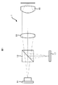
- FIG. 1 shows an example of an optical pickup optical system according to an embodiment of the present invention.
- FIG. 2 is a diagram (FIG. 2A) showing the wavefront (phase) of the laser light that passes through the pickup lens according to the present embodiment at the design wavelength and design temperature, and the ambient temperature becomes lower than the design temperature
- the laser FIG. 2B shows a wavefront (phase) of laser light that passes through the pickup lens according to the present embodiment when the wavelength of the light is shorter than the design wavelength (FIG. 2B), the ambient temperature becomes higher than the design temperature
- the laser It is a figure (Drawing 2 (c)) which shows the wavefront (phase) of the laser beam which permeate
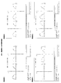
- FIG. 3 is a side view (a) showing an example of an optical pickup lens according to an embodiment of the present invention, and a side view (b) showing an example of an optical pickup lens similar to the embodiment of the present invention.
- FIG. 4 is a side view (a) showing an example of the optical pickup lens according to the embodiment of the present invention, and an enlarged view (b) showing an enlarged part of the side view (a).
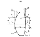
- FIG. 5 is a side view schematically showing the lens surface shape of the optical pickup lens.
- FIG. 6 is a side view schematically showing the lens surface shape of the optical pickup lens.
- FIG. 7 is a side view showing a conventional non-diffractive annular lens.
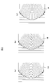
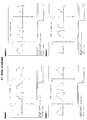
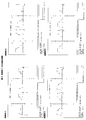
- FIG. 8 is a wavefront aberration diagram of Examples 1 to 4 of the present invention.
- FIG. 9 is a wavefront aberration diagram of Examples 5 to 8 of the present invention.
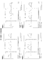
- FIG. 10 is a wavefront aberration diagram of Examples 9 to 12 of the present invention.
- FIG. 11 is a wavefront aberration diagram of Examples 13 to 16 of the present invention.
- FIG. 12 is a wavefront aberration diagram of Examples 17 to 20 of the present invention.
- FIG. 13 is a wavefront aberration diagram of Examples 21 to 24 of the present invention.
- FIG. 14 is a wavefront aberration diagram of Examples 25 to 28 of the present invention.
- FIG. 15 is a wavefront aberration diagram of Examples 29 to 30 of the present invention.
- FIG. 1 shows an example of an optical pickup optical system 1 according to an embodiment of the present invention.
- the optical pickup optical system 1 according to the present embodiment is used in an optical pickup device or an optical disc device according to the present invention.
- the optical pickup optical system 1 includes a light source 11 (laser light source), a beam splitter 12, a collimator lens 13, a pickup lens 14 (optical pickup objective lens), a detection system 16, and the like.
- a BD Blu-ray disc
- the optical disc 15 is used as the optical disc 15.
- the light source 11 includes a blue laser diode or the like used for BD.
- a beam splitter 12 is provided on the optical path of the laser light (light beam) emitted from the light source 11.
- a collimator lens 13 is provided on the optical path of the laser light emitted from the beam splitter 12.
- the collimator lens 13 adjusts the degree of divergence of the laser light emitted from the beam splitter 12 and emits the laser light.
- a pickup lens 14 is provided on the optical path of the laser light transmitted through the collimator lens 13.
- the pickup lens 14 has a function of collecting incident light on the information recording surface of the optical disc (BD) 15.
- BD a single layer BD having only one recording layer and a multilayer BD having a plurality of recording layers are known.
- the transparent substrate thickness of the single layer BD is 0.100 mm.
- the transparent substrate thickness of each recording layer of the two-layer BD having two recording layers is 0.075 mm and 0.100 mm.
- the pickup lens 14 When the pickup lens 14 focuses the laser beam on the recording layer of the two-layer BD, a large spherical aberration of about 0.25 ⁇ rms occurs due to a substrate thickness difference of 0.025 mm between the recording layers. Therefore, normally, the spherical aberration is corrected by moving the collimator lens 13 along the optical axis and adjusting the degree of divergence of the light beam incident on the pickup lens 14.
- correcting by moving the collimator lens 13 along the optical axis means adjusting the degree of divergence of the laser light incident on the pickup lens 14. This is equivalent to adjusting the virtual issue point position (object position) of the light incident on the pickup lens 14 and causing the pickup lens 14 to enter from the virtual issue point position without passing through the collimator lens 13. is there.
- the spherical aberration is corrected by adjusting the object distance of the pickup lens 14.
- the pickup lens 14 according to the embodiment of the present invention is favorably gathered at 0.0875 mm, which is an intermediate transparent substrate thickness of the transparent substrate thickness (0.075 mm, 0.100 mm) of each recording layer in the two-layer BD. Designed to shine.
- 0.0875 mm is an intermediate transparent substrate thickness of the transparent substrate thickness (0.075 mm, 0.100 mm) of each recording layer in the two-layer BD.
- the thickness of the transparent substrate that can be used by the pickup lens 14 according to the embodiment of the invention is not limited to 0.0875 mm designed in this example.
- the transparent substrate of the optical disk 15 is polycarbonate (PC).
- the pickup lens 14 further has a function of guiding the laser beam reflected by the information recording surface of the optical disc 15 to the detection system 16.
- a plurality of annular zones that are concentric with the optical axis of the pickup lens 14 are formed on both surfaces of the lens surface (R1 surface) on the laser light source side and the lens surface (R2 surface) on the optical disk side of the pickup lens 14. Yes. Further, a step is formed between adjacent annular zones.
- At least one surface of the pickup lens 14 is divided into a plurality of annular regions having the optical axis of the pickup lens 14 concentric by a plurality of steps.
- the pickup lens 14 is formed from a plastic material.
- the steps of the plurality of steps formed on both the laser light source side lens surface (R1 surface) and the optical disk side lens surface (R2 surface) of the pickup lens 14 are at the design wavelength and design temperature (the wavelength of the laser light is designed).
- the wavelength of the laser light incident when the ambient temperature is the design temperature) is set so that the adjacent annular zones differ from each other by an approximately integer multiple of the wavelength.
- the plurality of steps formed on the pickup lens 14 have a step amount that causes a phase difference in the laser light so as to reduce aberrations that occur due to changes in the ambient temperature.
- the substantially integer multiple of the wavelength is preferably (integer) ⁇ 0.999 times the wavelength to (integer) ⁇ 1.001 times the wavelength.
- the substantially integer multiple of the wavelength may be (integer) ⁇ 0.995 times the wavelength to (integer) ⁇ 1.005 times the wavelength. Even in this case, the wavefront aberration generated when the ambient temperature changes can be sufficiently reduced by the step formed on the pickup lens 14.
- the pickup lens 14 is operated by an actuator (not shown).
- the laser light emitted from the light source 11 passes through the beam splitter 12 and enters the collimator lens 13.
- the collimator lens 13 adjusts the degree of divergence of the laser light emitted from the beam splitter 12 and emits the laser light.
- the laser beam that has passed through the collimator lens 13 enters the pickup lens 14.
- the plurality of steps provided in the pickup lens 14 correct the phase of the laser beam so as to reduce the aberration caused by the change in the ambient temperature. .
- the pickup lens 14 focuses the corrected laser beam on the information recording surface of the optical disc 15.
- the laser beam reflected by the information recording surface of the optical disc 15 enters the detection system 16 via the pickup lens 14 and is detected.
- the detection system 16 detects the laser beam and performs photoelectric conversion to generate a focus servo signal, a track servo signal, a reproduction signal, and the like.
- the optical pickup lens according to the present embodiment focuses laser light having a wavelength in the range of 395 nm to 415 nm on the information recording surface of a BD (Blu-ray disc).
- the numerical aperture NA of the optical pickup lens according to the present embodiment is 0.8 or more.
- the optical pickup lens according to the present invention is divided into a plurality of concentric annular zones on the lens surface (R1 surface) on the laser light source side and the lens surface (R2 surface) on the optical disk side by steps.
- An annular zone structure is provided.
- both the laser light source side lens surface (R1 surface) and the optical disk side lens surface (R2 surface) of the optical pickup lens according to the present invention are concentrically divided into a plurality of annular zones, A step is formed between adjacent annular zones.
- optical pickup lens 14 used in the optical pickup optical system 1 according to the embodiment of the present invention will be described in detail.
- FIG. 2 is a diagram showing the optical pickup lens 14 in the optical pickup optical system 1 according to the present embodiment.
- 2A shows the wavefront (phase) of the laser beam at the design wavelength and the design temperature
- FIG. 2B shows the laser beam wavelength shorter than the design wavelength because the ambient temperature is lower than the design temperature.
- FIG. 2 (c) shows the wavefront (phase) of the laser light when the ambient temperature is higher than the design temperature and the wavelength of the laser light is longer than the design wavelength. Is shown.
- the plurality of steps described above are provided on the surface of the optical pickup lens 14 on the light source 11 side.
- the step amounts of the plurality of steps are set such that the phase of the transmitted laser light is different from each other in the adjacent annular zone regions by an approximately integer multiple of the wavelength. Further, the step of the optical pickup lens 14 has a step amount that causes a phase difference in the laser beam so as to reduce aberration caused by the change of the ambient temperature when the ambient temperature changes.
- the phases of the laser light transmitted through each annular zone differ from each other by an integral multiple of the wavelength. Therefore, as shown in FIG. 2A, at the design wavelength and design temperature, there is no phase difference in the laser light transmitted through different annular zones. Therefore, the laser light incident on the optical pickup lens 14 is emitted with the same phase. Accordingly, at the design wavelength and design temperature, the aberration of the laser beam condensed by the optical pickup lens 14 is the same as when no step is formed.
- the phase difference is sized so as to reduce aberrations caused by changes in ambient temperature. For this reason, when the ambient temperature changes, conventionally, aberrations collected by the optical pickup lens increase. However, in the present invention, due to the phase difference of the laser light transmitted through each annular zone of the optical pickup lens 14. In addition, an increase in aberration associated with a change in ambient temperature is suppressed. Then, the laser beam emitted from the optical pickup lens 14 is favorably condensed on the information recording surface of the optical disc 15.
- each annular region is defined as a first annular zone, a second annular zone, ..., an Nth annular zone (N is a positive integer) from the lens center toward the lens outer edge.
- N is a positive integer
- the intersection of the aspherical surface and the optical axis passing through the lens center is defined as C n (N is an integer satisfying 1 ⁇ n ⁇ N)
- the distance between the intersection C 1 and the intersection C n is the axial step amount D n, and is parallel to the optical axis toward the optical disc (from the laser light source to the optical disc).
- the ring zone structure satisfies D m ⁇ 1 ⁇ D m and D m > D m + 1 when D n > 0, or D m ⁇ 1 > D m and D m ⁇ D when D n ⁇ 0.
- At least one m-th zone that satisfies D m + 1 is provided.
- a step is formed in the direction in which the axial step amount Dn increases from the lens center toward the lens outer edge
- the m th In the range on the lens outer edge side from the annular zone, a step is formed in the direction in which the axial step amount D n decreases from the lens center toward the lens outer edge.
- a step is formed in the direction from the lens center toward the lens outer edge in a direction in which the axial step amount D n decreases in the range closer to the lens center than the m-th ring zone.
- a step is formed in the direction in which the axial step amount D n increases from the lens center toward the lens outer edge.
- a step is formed in the direction in which the lens center thickness is reduced between adjacent annular zones in the range closer to the lens center than the m-th annular zone from the lens center toward the lens outer edge.
- a step is formed between adjacent annular zones in a direction in which the lens center thickness increases.
- a step is formed in the direction from the center of the lens toward the outer edge of the lens in the direction closer to the center of the lens than the m-th zone in the direction in which the lens center thickness increases between adjacent zones.
- a step is formed between adjacent annular zones in a direction in which the lens center thickness becomes thinner. That is, when D n > 0, the lens zone structure is formed such that the lens center thickness in the m-th zone is the thinnest, and when D n ⁇ 0, the lens center thickness in the m-th zone is the thickest.
- An annular structure is formed so as to be.
- the annular structure includes a junction region provided between at least one n ⁇ 1 annular zone and the nth annular zone that satisfies D n ⁇ 1 > D n .
- the surface shape of the junction region is such that the positions in the optical axis direction of substantially all points on the surface of the junction region are more than the positions in the optical axis direction of the boundary on the lens outer edge side of the n-1 zone.
- the shape is on the optical disc side.
- the annular structure includes a junction region between at least one n ⁇ 1 annular zone and the nth annular zone satisfying D n ⁇ 1 > D n. Yes.
- the surface shape of the junction region is such that the positions in the optical axis direction of substantially all points on the surface of the junction region are more than the positions in the optical axis direction of the boundary on the lens outer edge side of the n-1th annular zone. The shape is also on the optical disc side.
- the surface shape of the joining region is a shape that does not protrude toward the laser light source side from the lens outer edge side boundary of the (n-1) -th zone. Therefore, a problem in forming an optical pickup lens due to the formation of the protrusions between adjacent annular zones is less likely to occur. Therefore, it is possible to provide an optical pickup lens that is easier to mold.
- FIG. 3A shows an example of an optical pickup lens according to the embodiment of the present invention.
- an annular structure is formed on the lens surface 101 on the laser light source side.
- An annular structure is also formed on the lens surface 102 of the optical pickup lens 14 on the optical disk side.
- the ring zone structure includes one m- th zone 103 that satisfies D m ⁇ 1 ⁇ D m and D m > D m + 1 .
- a step is formed in the direction in which the axial step amount Dn increases from the lens center toward the lens outer edge, and the lens outside the lens from the m-th zone 103.
- a step is formed in the direction in which the axial step amount Dn decreases from the lens center toward the lens outer edge.
- a step is formed in the direction in which the lens center thickness becomes thinner between adjacent ring zones.
- a step is formed in the direction in which the lens center thickness increases between adjacent annular zones. That is, the annular structure is formed so that the lens center thickness in the m-th annular zone 103 is the thinnest.
- the optical pickup lens 14-1 shown in FIG. 3A is provided with an annular structure on the disk side opposite to the laser light source side, so that a desired phase difference can be obtained with light rays passing between the annular areas.
- a desired phase difference can be obtained with light rays passing between the annular areas.
- an optical pickup lens 14-1 having an annular structure only on the laser light source side is shown in FIG.
- an annular structure is formed on the lens surface 101 on the laser light source side.
- the lens surface 102 on the optical disc side of the optical pickup lens 14 is not formed with an annular structure, and the surface shape of the lens surface 102 on the optical disc side is a single aspherical shape.
- FIG. 3 (a) and 3 (b) have the same optical characteristics, although the shape of the disk side opposite to the laser light source is different. Comparing FIG. 3 (a) and FIG. 3 (b), it can be seen that the depth of the annular zone step in the first annular zone and the second annular zone formed on the laser light source side is shallow.
- the on-axis step amount D n has been described.
- the on-axis step amount D n can be set to a completely different value in a lens having a zonal structure.
- the same effect as the present invention can be obtained. This is because different sag amounts on the axis can be obtained to obtain the same sag amount as the sag amount at the position of the radius away from the optical axis. This is apparent from the aspherical surface that defines the surface shape described later.
- the ring zone structure includes a junction region 104 provided between the n-1 zone and the n-th zone that satisfies D n-1 > D n .
- the junction region 104 may be provided between at least one n ⁇ 1 annular zone and the nth annular zone that satisfy D n ⁇ 1 > D n .
- the surface shape of the joining region 104 is such that the positions in the optical axis direction of substantially all points on the surface of the joining region 104 are the positions in the optical axis direction of the boundary on the lens outer edge side of the n-1 ring zone. The shape is closer to the optical disc side.
- the surface shape of the joining region 104 is a shape that does not protrude toward the laser light source side from the boundary on the lens outer edge side of the (n ⁇ 1) th zone. More specifically, in the optical pickup lens 14-1, the surface shape of the bonding region 104 is a planar shape perpendicular to the optical axis.
- FIG. 4A shows another example of the optical pickup lens according to the embodiment of the present invention.
- the optical pickup lens 14-2 shown in FIG. 4 (a) has substantially the same structure as the optical pickup lens 1 shown in FIG. 3 (a). Specifically, an annular structure is formed on the lens surface 201 on the laser light source side, and an annular structure is also formed on the surface shape of the lens surface 202 on the optical disk side.
- the ring zone structure includes one m- th ring zone 203 that satisfies D m ⁇ 1 ⁇ D m and D m > D m + 1 . That is, the annular structure is formed so that the lens center thickness in the m-th annular zone 203 is the thinnest.
- the ring zone structure includes a junction region 204 provided between the n-1 zone and the n-th zone that satisfies D n-1 > D n .
- the junction region 204 may be provided between at least one n ⁇ 1 annular zone and the nth annular zone that satisfy D n ⁇ 1 > D n .
- the surface shape of the joining region 204 is a shape that does not protrude toward the laser light source side from the boundary on the lens outer edge side of the (n ⁇ 1) th zone.
- FIG. 4B shows an enlarged view of a portion satisfying D n ⁇ 1 > D n (a portion surrounded by a one-dot chain line in FIG. 4A) in the optical pickup lens 14-2.
- the surface shape of the bonding region 204 is an angle ⁇ (°) in a direction from the surface perpendicular to the optical axis toward the optical disc side from the laser light source side. It has an inclined planar shape.
- the surface shape of the bonding region 204 satisfies the following expression (9). 0 ⁇ ⁇ ⁇ 15 (9)
- the inclination angle of the (n-1) -th zone and the inclination angle of the joining region 204 can be made close to each other.
- the shrinkage direction in the (n ⁇ 1) -th zone during molding and the shrinkage direction in the joining region 204 can be matched as much as possible. Therefore, it becomes possible to easily find molding conditions for accurately obtaining the dimensions of the optical pickup lens 2.
- the inclination angles of the plurality of joining regions 204 provided in one optical pickup lens 2 are different depending on the positions in the lens radial direction where the joining regions 204 are provided. (For example, ⁇ 1, ⁇ 2, and ⁇ 3 shown in FIG. 4B).
- a transparent resin material represented by polyolefin resin, polycarbonate resin, acrylic resin, epoxy resin, ABS resin, glass, or the like can be used.
- a laser beam having a wavelength of 405 nm is usually used for recording / reproducing BD, it is preferable to use a transparent resin material having a high transmittance of a laser beam having a wavelength in the range of 395 nm to 415 nm.
- transparent resin materials include cycloolefin polymers and cyclic olefin polymers.
- the optical pickup lens 14 can be manufactured by injection molding these transparent resin materials.
- the optical pickup lens 14 may be molded by a 2P (Photo-Polymer) method.
- the optical pickup lens 14 may be cured by irradiating with ultraviolet rays after pouring a resin that cures at a specific wavelength, for example, an ultraviolet curable resin into a mold.
- the optical pickup lens 14 may be molded by pouring a resin material such as epoxy into a mold, mixing and curing.
- the optical pickup lens 14 may be molded by pouring and mixing a resin that cures at a specific temperature into a mold.
- optical glass may be used, or polishing or molding may be used.
- FIG. 5 is a side view showing an objective lens which is an example of a pickup lens.
- the definition of the surface shapes of the lens surface (R1 surface) on the laser light source side and the lens surface (R2 surface) on the optical disk side of the optical pickup lens 14 will be described.
- the direction is parallel to the optical axis and is directed from the laser light source side lens surface (R1 surface) to the optical disk side lens surface (R2 surface). The direction is the positive direction.
- the surface shape of the disk side surface (R2 surface) of the optical pickup lens 14 in the present embodiment will be described.
- the vertex of the light incident surface R2 of the objective lens is e
- the point of the light ray height h on the tangent surface in contact with the vertex e and the light incident surface R1 in a direction parallel to the optical axis OA from this point c.
- the distance Z B (mm) between the points c and d with respect to an arbitrary ray height h (mm) is As shown, the surface shape of the disk side surface (R2 surface) is formed.
- the vertex of the light incident surface R1 of the objective lens is f
- the point of the ray height h on the tangent surface in contact with the vertex f is a
- the upper point is b
- the distance Z A (mm) between the points a and b with respect to an arbitrary ray height h (mm) is As shown, the surface shape of the laser side surface (R1 surface) is formed.
- the Nth annular region (N is a positive integer) of the pickup lens 14 according to the present embodiment are defined (21)
- the value of the annular zone position of the first annular zone region, the second annular zone region,..., The N-th annular zone shown in Table 5 is substituted for the ray height h in the equation.
- the equation (21) and the coefficients shown in Table 5 are used.
- the surface shape of the first to N-th zone regions of the pickup lens 14 according to the first example is defined by the value of.
- a junction region formed after the m-th annular zone (m is an integer satisfying 1 ⁇ m ⁇ N) can be expressed by using the equation (21).
- the surface shape of the joining region of the pickup lens 14 is also defined.
- FIG. 6 is a side view schematically showing the pickup lens 14.
- the adjacent step amount is a step amount between the annular zones.
- the sign of the adjacent step amount d is the same as that of so-called geometric optics, and the innermost point of the next annular zone from the outermost point of the annular zone on the lens center side is the disc side (in FIG. 6).
- the sign of + (plus) is taken when it becomes the right side of (-), and the sign of-(minus) is taken when it becomes the laser side (left side in FIG. 6).
- the lens surface (R1 surface) on the laser light source side or the lens surface (R2 surface) on the optical disk side of the optical pickup lens 14 is not limited to the above-described surface shape.
- a structure may be formed on the laser light source (R1 surface) or the optical disk side lens surface (R2 surface).
- the surface shape of the lens surface (R1 surface) on the laser light source side of the optical pickup lens 14 is not limited to the above-described surface shape.
- an annular zone having a certain width and depth may be formed concentrically or spirally on the laser light source side lens (R1 surface) or the optical disk side lens surface (R2 surface).
- a film for controlling the transmittance of incident light is formed on the lens surface (R1 surface) on the laser light source side of the optical pickup lens 14 or the lens surface (R2 surface) on the optical disk side. May be.
- the film thickness and material of these films are selected so that the desired transmittance performance of the optical pickup lens 14 can be achieved.
- these films may have a single-layer structure including a single thin film, or may have a multiple-layer structure in which a plurality of thin films are stacked. When these films are composed of a plurality of thin films, thin films of different materials may be alternately stacked.
- each figure has two figures on the left and right, but shows two directions perpendicular to the optical axis, and the horizontal axis shows the relative pupil coordinates when the effective radius of each embodiment is 1, and the vertical axis.
- the axis is wavefront aberration ( ⁇ ).
- the display range is ⁇ 1 on the horizontal axis and ⁇ 50 ⁇ on the vertical axis.
- Tables 1 to 3 show a list of refractive indexes of the optical pickup lens 14 and the disk 15 used in Examples 1 to 30.
- the meaning of each symbol in the wavefront aberration characteristic is as follows.
- TOTAL TOTAL wavefront aberration SA3: third-order spherical aberration COMA3: third-order coma aberration
- AS3 third-order astigmatism
- Table 4 shows configurations in Examples 1 to 30.
- Table 5 shows lens data of the optical pickup lens 14 in Examples 1 to 30.
- Table 6 shows the amount of adjacent steps in Examples 1 to 30 (however, only between the annular zones inside the valley annular zone).
- Table 7 shows a comparison table corresponding to each claim in Examples 1 to 30.
- Table 8 shows a comparison table of optical characteristics in Examples 1 to 30.
- Table 9 shows a comparison table of the sixth zone sag (Z A ) of Example 2 and the sixth zone sag of Example 30.
- Example 30 only Example 30 will be described in detail.
- Example 2 shown in (Table 5) was changed from 0.005410305 mm to 0.008 mm.
- Light source (laser light source) 12 Beam splitter 13 Collimator lens 14 Pickup lens (Optical pickup objective lens) 14-1 Pickup Lens 14-2 Pickup Lens 15 Optical Disk 16 Detection System 101 Lens Surface 102 Lens Surface 103 M-th Ring Zone 104 Joining Area 201 Lens Face 202 Lens Face 203 M-th Ring Zone 204 Joining Area
Abstract
L'invention concerne une lentille pour enregistreur optique, une structure de zones orbiculaires servant à la prévention de la détérioration d'aberration causée par une variation de la longueur d'onde ou un changement de température pouvant être formée avec une précision supérieure. Une lentille pour objectif d'enregistreur optique en plastique (14) servant à concentrer un flux de lumière provenant d'une source de lumière laser (11) sur un disque optique, par exemple un disque Blu-ray, comprend une structure de zones orbiculaires comprenant une pluralité de zones orbiculaires sur les deux surfaces qui sont une surface de lentille (surface R1) (101) du côté de la source de lumière laser (11) et une surface de lentille (surface R2) (102) du côté du disque optique, les surfaces de lentille étant divisées par marches en une pluralité de zones orbiculaires concentriques (103), des zones de connexion (104) sont disposées entre les zones orbiculaires respectives, et la pluralité de marches sont configurées de manière à ce que les hauteurs des marches fassent générer par le flux de lumière d'entrée des différences de phases telles qu'elles réduisent l'aberration produite dans la lentille pour objectif d'enregistreur optique (14) lorsque la température ambiante change, et qu'elles satisfont NA ≥ 0,8 et 1,0 ≤ f ≤ 1,8, NA représentant une ouverture numérique de la lentille pour objectif d'enregistreur optique (14) et f (mm) représentant une longueur focale.
Applications Claiming Priority (2)
| Application Number | Priority Date | Filing Date | Title |
|---|---|---|---|
| JP2010106448A JP2011238304A (ja) | 2010-05-06 | 2010-05-06 | 光ピックアップレンズ |
| JP2010-106448 | 2010-05-06 |
Publications (1)
| Publication Number | Publication Date |
|---|---|
| WO2011138919A1 true WO2011138919A1 (fr) | 2011-11-10 |
Family
ID=44903771
Family Applications (1)
| Application Number | Title | Priority Date | Filing Date |
|---|---|---|---|
| PCT/JP2011/060282 WO2011138919A1 (fr) | 2010-05-06 | 2011-04-27 | Lentille pour enregistreur optique |
Country Status (2)
| Country | Link |
|---|---|
| JP (1) | JP2011238304A (fr) |
| WO (1) | WO2011138919A1 (fr) |
Citations (6)
| Publication number | Priority date | Publication date | Assignee | Title |
|---|---|---|---|---|
| JP2004101954A (ja) * | 2002-09-10 | 2004-04-02 | Konica Minolta Holdings Inc | 合成樹脂製レンズ及びこれを用いた光ピックアップ装置 |
| JP2004310976A (ja) * | 2003-03-26 | 2004-11-04 | Asahi Glass Co Ltd | 光ピックアップ装置 |
| JP2005050433A (ja) * | 2003-07-29 | 2005-02-24 | Asahi Glass Co Ltd | 対物レンズ及び光ヘッド装置 |
| JP2006024344A (ja) * | 2004-06-11 | 2006-01-26 | Nidec Nissin Corp | 輪帯位相補正レンズおよび光ヘッド装置 |
| JP2009295244A (ja) * | 2008-06-06 | 2009-12-17 | Ricoh Co Ltd | 光学素子、光ピックアップおよび光情報処理装置 |
| JP2010080040A (ja) * | 2008-04-10 | 2010-04-08 | Hitachi Maxell Ltd | 光ピックアップ対物レンズ、光ピックアップ装置及び光ディスク装置 |
-
2010
- 2010-05-06 JP JP2010106448A patent/JP2011238304A/ja active Pending
-
2011
- 2011-04-27 WO PCT/JP2011/060282 patent/WO2011138919A1/fr active Application Filing
Patent Citations (6)
| Publication number | Priority date | Publication date | Assignee | Title |
|---|---|---|---|---|
| JP2004101954A (ja) * | 2002-09-10 | 2004-04-02 | Konica Minolta Holdings Inc | 合成樹脂製レンズ及びこれを用いた光ピックアップ装置 |
| JP2004310976A (ja) * | 2003-03-26 | 2004-11-04 | Asahi Glass Co Ltd | 光ピックアップ装置 |
| JP2005050433A (ja) * | 2003-07-29 | 2005-02-24 | Asahi Glass Co Ltd | 対物レンズ及び光ヘッド装置 |
| JP2006024344A (ja) * | 2004-06-11 | 2006-01-26 | Nidec Nissin Corp | 輪帯位相補正レンズおよび光ヘッド装置 |
| JP2010080040A (ja) * | 2008-04-10 | 2010-04-08 | Hitachi Maxell Ltd | 光ピックアップ対物レンズ、光ピックアップ装置及び光ディスク装置 |
| JP2009295244A (ja) * | 2008-06-06 | 2009-12-17 | Ricoh Co Ltd | 光学素子、光ピックアップおよび光情報処理装置 |
Also Published As
| Publication number | Publication date |
|---|---|
| JP2011238304A (ja) | 2011-11-24 |
Similar Documents
| Publication | Publication Date | Title |
|---|---|---|
| US6118594A (en) | Objective lens for optical pick-up | |
| TWI393132B (zh) | 光學元件、像差校正元件、光收斂元件、物鏡光學系統、光學攝像裝置、和光學資訊記錄再生裝置 | |
| US7123424B2 (en) | Objective lens for optical information recording medium | |
| US7755998B2 (en) | Optical pickup system, optical head, optical disk apparatus, and objective lens | |
| JP4060007B2 (ja) | 光ディスク装置の光学系 | |
| US7957249B2 (en) | Objective lens, optical pickup apparatus and optical information recording and/or reproducing apparatus | |
| JP2003167187A (ja) | 対物レンズ、光ピックアップ装置及び記録・再生装置 | |
| EP1562187A2 (fr) | Appareil de lecture optique et appareil d'enregistrement et/ou de reproduction optique d'informations | |
| US7924685B2 (en) | Objective lens | |
| WO2005117002A1 (fr) | Système optique à objectif, dispositif de prélèvement optique et dispositif de lecteur de disque optique | |
| JP4531649B2 (ja) | 反射防止膜、光ピックアップ用光学部品、対物レンズ及び光ピックアップ用光学部品の製造方法 | |
| KR100506565B1 (ko) | 광 디스크용 대물 렌즈 | |
| JP4296868B2 (ja) | 光ピックアップ装置用の光学系、光ピックアップ装置及び光情報記録再生装置 | |
| JP4852271B2 (ja) | 光ピックアップ光学系、光ヘッド及び光ディスク装置 | |
| WO2011138919A1 (fr) | Lentille pour enregistreur optique | |
| WO2011013339A1 (fr) | Lentille de detection de lumiere | |
| JP2005535063A (ja) | 2種類の材料で形成された対物レンズを含むスキャン装置 | |
| JP4232188B2 (ja) | 光ピックアップ装置用の対物レンズ、光ピックアップ装置及び光情報記録再生装置 | |
| JP2012053958A (ja) | 光ピックアップ用対物レンズおよび光ピックアップ装置 | |
| JP5119080B2 (ja) | 光学記録読み取り用ピックアップ用光学素子 | |
| JP2006114081A (ja) | 対物レンズ及び光ピックアップ装置 | |
| JP5180138B2 (ja) | 光ピックアップレンズ | |
| JP2010281847A (ja) | 対物レンズ | |
| JP2005050433A (ja) | 対物レンズ及び光ヘッド装置 | |
| JP2009146486A (ja) | レンズユニット、収差補正用素子、及び収差補正用素子の設計方法 |
Legal Events
| Date | Code | Title | Description |
|---|---|---|---|
| 121 | Ep: the epo has been informed by wipo that ep was designated in this application |
Ref document number: 11777438 Country of ref document: EP Kind code of ref document: A1 |
|
| NENP | Non-entry into the national phase |
Ref country code: DE |
|
| 122 | Ep: pct application non-entry in european phase |
Ref document number: 11777438 Country of ref document: EP Kind code of ref document: A1 |