WO2011136033A1 - 通信システム、送信装置、受信装置、プログラム、及びプロセッサ - Google Patents
通信システム、送信装置、受信装置、プログラム、及びプロセッサ Download PDFInfo
- Publication number
- WO2011136033A1 WO2011136033A1 PCT/JP2011/059288 JP2011059288W WO2011136033A1 WO 2011136033 A1 WO2011136033 A1 WO 2011136033A1 JP 2011059288 W JP2011059288 W JP 2011059288W WO 2011136033 A1 WO2011136033 A1 WO 2011136033A1
- Authority
- WO
- WIPO (PCT)
- Prior art keywords
- unit
- constraint length
- bits
- decoding
- decoding unit
- Prior art date
- Legal status (The legal status is an assumption and is not a legal conclusion. Google has not performed a legal analysis and makes no representation as to the accuracy of the status listed.)
- Ceased
Links
Images


Classifications
-
- H—ELECTRICITY
- H03—ELECTRONIC CIRCUITRY
- H03M—CODING; DECODING; CODE CONVERSION IN GENERAL
- H03M13/00—Coding, decoding or code conversion, for error detection or error correction; Coding theory basic assumptions; Coding bounds; Error probability evaluation methods; Channel models; Simulation or testing of codes
- H03M13/29—Coding, decoding or code conversion, for error detection or error correction; Coding theory basic assumptions; Coding bounds; Error probability evaluation methods; Channel models; Simulation or testing of codes combining two or more codes or code structures, e.g. product codes, generalised product codes, concatenated codes, inner and outer codes
- H03M13/2957—Turbo codes and decoding
- H03M13/296—Particular turbo code structure
-
- H—ELECTRICITY
- H03—ELECTRONIC CIRCUITRY
- H03M—CODING; DECODING; CODE CONVERSION IN GENERAL
- H03M13/00—Coding, decoding or code conversion, for error detection or error correction; Coding theory basic assumptions; Coding bounds; Error probability evaluation methods; Channel models; Simulation or testing of codes
- H03M13/63—Joint error correction and other techniques
- H03M13/6306—Error control coding in combination with Automatic Repeat reQuest [ARQ] and diversity transmission, e.g. coding schemes for the multiple transmission of the same information or the transmission of incremental redundancy
-
- H—ELECTRICITY
- H04—ELECTRIC COMMUNICATION TECHNIQUE
- H04L—TRANSMISSION OF DIGITAL INFORMATION, e.g. TELEGRAPHIC COMMUNICATION
- H04L1/00—Arrangements for detecting or preventing errors in the information received
- H04L1/004—Arrangements for detecting or preventing errors in the information received by using forward error control
- H04L1/0041—Arrangements at the transmitter end
-
- H—ELECTRICITY
- H04—ELECTRIC COMMUNICATION TECHNIQUE
- H04L—TRANSMISSION OF DIGITAL INFORMATION, e.g. TELEGRAPHIC COMMUNICATION
- H04L1/00—Arrangements for detecting or preventing errors in the information received
- H04L1/004—Arrangements for detecting or preventing errors in the information received by using forward error control
- H04L1/0056—Systems characterized by the type of code used
- H04L1/0064—Concatenated codes
- H04L1/0066—Parallel concatenated codes
-
- H—ELECTRICITY
- H04—ELECTRIC COMMUNICATION TECHNIQUE
- H04L—TRANSMISSION OF DIGITAL INFORMATION, e.g. TELEGRAPHIC COMMUNICATION
- H04L1/00—Arrangements for detecting or preventing errors in the information received
- H04L1/12—Arrangements for detecting or preventing errors in the information received by using return channel
- H04L1/16—Arrangements for detecting or preventing errors in the information received by using return channel in which the return channel carries supervisory signals, e.g. repetition request signals
- H04L1/18—Automatic repetition systems, e.g. Van Duuren systems
- H04L1/1812—Hybrid protocols; Hybrid automatic repeat request [HARQ]
- H04L1/1819—Hybrid protocols; Hybrid automatic repeat request [HARQ] with retransmission of additional or different redundancy
-
- H—ELECTRICITY
- H03—ELECTRONIC CIRCUITRY
- H03M—CODING; DECODING; CODE CONVERSION IN GENERAL
- H03M13/00—Coding, decoding or code conversion, for error detection or error correction; Coding theory basic assumptions; Coding bounds; Error probability evaluation methods; Channel models; Simulation or testing of codes
- H03M13/03—Error detection or forward error correction by redundancy in data representation, i.e. code words containing more digits than the source words
- H03M13/05—Error detection or forward error correction by redundancy in data representation, i.e. code words containing more digits than the source words using block codes, i.e. a predetermined number of check bits joined to a predetermined number of information bits
- H03M13/09—Error detection only, e.g. using cyclic redundancy check [CRC] codes or single parity bit
Definitions
- the present invention relates to a communication system, a transmission device, a reception device, a program, and a processor.
- This application claims priority based on Japanese Patent Application No. 2010-105157 filed in Japan on April 30, 2010, the contents of which are incorporated herein by reference.
- a technique for compensating for such deterioration in communication quality with an error correction code is known.
- a receiving apparatus using such a technique cannot always correctly decode data. Therefore, it is known that the receiving apparatus performs retransmission control (automatic retransmission control, also referred to as ARQ (Automatic Repeat reQuest)) for transmitting the same data again when the data cannot be correctly decoded.
- ARQ Automatic Repeat reQuest
- the retransmission control includes non-adaptive ARQ (Non-adaptive ARQ) and adaptive ARQ (Adaptive ARQ).
- Non-adaptive ARQ uses the same transmission method for retransmission data and initial transmission data.
- the Chase Combining method is used for a technique to which non-adaptive ARQ is applied.
- a technique to which adaptive ARQ is applied a technique described in Patent Document 1 is known.
- a turbo code that can achieve characteristics close to the Shannon limit is known as an error correction code (see Non-Patent Document 1).
- a recursive systematic convolutional (RSC) code of a plurality of component encoders is connected in parallel.
- a turbo equalizer that applies an iterative decoding method based on the turbo principle used in a turbo code decoding process to a MAP (Maximum A Positive Probability) detector and a decoding unit. It is coming.
- a technique described in Patent Document 2 is known.
- the present invention has been made in view of the above points, and provides a communication system, a transmission device, a reception device, a program, and a processor that can improve communication quality.
- the present invention has been made to solve the above problem, and the present invention generates a retransmission signal by encoding bits with a constraint length different from the constraint length used in the previous transmission, A transmission device that transmits the generated retransmission signal, and a reception device that decodes the bit with a constraint length different from the constraint length used in the previous reception and performs turbo equalization using the bits of the retransmission signal.
- This is a communication system characterized by the above.
- the present invention is characterized in that, in the communication system, the previous transmission is an initial transmission.
- the transmission device includes a turbo coding unit that encodes bits with a constraint length different from the constraint length used in the previous transmission
- the reception device includes: A decoding unit for decoding bits with a constraint length different from the constraint length used in the previous reception is provided.
- the turbo encoding unit includes a first encoding unit that encodes bits and a constraint length different from a constraint length in the first encoding unit.
- a second encoding unit that encodes the bits, encoding the bits of the signal in the previous transmission using the first encoding unit, and using the second encoding unit Then, the bits of the retransmission signal are encoded.
- the decoding unit has a first decoding unit that decodes a bit and a bit having a constraint length different from a constraint length in the first decoding unit.
- the decoding unit has a first decoding unit that decodes a bit and a bit having a constraint length different from a constraint length in the first decoding unit.
- a second decoding unit for decoding wherein the first decoding unit and the second decoding unit are connected in series.
- the transmitting apparatus rearranges and encodes the bit sequence in an order different from the order used in the previous transmission, and the receiving apparatus performs the previous reception.
- the decoding is performed by rearranging the bit strings in an order different from the used order.
- the transmission device has a first encoding unit that encodes bits and a constraint length different from a constraint length in the first encoding unit.
- a second encoding unit that encodes the bits, encoding the bits of the signal in the previous transmission using the first encoding unit, and using the second encoding unit.
- the bits of the retransmission signal which are bits in which the bit string is rearranged in an order different from the order used in the previous transmission, are encoded.
- the receiving device has a first decoding unit that decodes a bit and a bit having a constraint length different from a constraint length in the first decoding unit.
- a second decoding unit for decoding, decoding the bits of the signal in the previous reception using the first decoding unit, and for the previous reception using the second encoding unit It is characterized in that the bit of the retransmission signal is decoded, which is a bit in which the bit string is rearranged in an arrangement order different from the arrangement order.
- the receiving device has a first decoding unit that decodes a bit and a bit having a constraint length different from a constraint length in the first decoding unit.
- the first decoding unit performs decoding using the decoded bits.
- the present invention is characterized in that the constraint length used for the retransmission signal is shorter than the constraint length used in the previous transmission.
- a constraint length used for the retransmission signal is determined based on information indicating convergence of the turbo code, and information indicating convergence of the turbo code is retransmission The number of times or the number of retransmissions and the coding rate, the number of receiving antennas of the receiving device, the number of modulation levels, the overlapping bandwidth, or the bandwidth for clipping.
- the present invention is a transmission device characterized in that a retransmission signal is generated by encoding bits with a constraint length different from the constraint length used in the previous transmission, and the generated retransmission signal is transmitted. is there.
- the present invention is a receiving apparatus characterized in that a bit is decoded with a constraint length different from the constraint length used in the previous reception, and turbo equalization is performed using bits of the retransmission signal. .
- the present invention is a program for causing a computer of a transmission apparatus to execute a procedure for generating a retransmission signal by encoding bits with a constraint length different from the constraint length used in the previous transmission.
- the present invention also executes a procedure for turbo equalization using bits of the retransmission signal, which are bits decoded with a constraint length different from the constraint length used in the previous reception, to the computer of the reception apparatus. It is a program to make it.
- the present invention is a processor that encodes bits of a retransmission signal with a constraint length different from the constraint length used in the previous transmission.
- the present invention is a processor for decoding bits of a retransmission signal with a constraint length different from the constraint length used in the previous reception.
- FIG. 10 is a schematic diagram illustrating a configuration of a code unit according to Modification 4. It is a schematic block diagram which shows the structure of the mobile station apparatus which concerns on the 2nd Embodiment of this invention. It is a schematic block diagram which shows the structure of the turbo code
- FIG. 10 is a schematic block diagram illustrating a configuration of a turbo code unit according to Modification 5. FIG.
- FIG. 10 is a schematic block diagram illustrating a configuration of a decoding unit according to Modification 5.
- FIG. 10 is a schematic block diagram illustrating a configuration of a decoding unit D5 according to Modification 6. It is the schematic which shows an example of arrangement
- FIG. 14 is a schematic diagram illustrating an example of a constraint length table according to Modification 11.
- FIG. 14 is a schematic block diagram which shows the structure of the decoding part which concerns on a prior art.
- FIG. 1 is a conceptual diagram of a communication system in each embodiment.
- mobile station devices User Equipment; user equipment
- eNodeB base station apparatus
- Base station apparatus eNodeB; base station apparatus
- a mobile station apparatus 1A includes a plurality of antennas and performs data transmission such as MIMO (Multiple Input Multiple Output) transmission and transmission diversity.
- the mobile station devices 2A and 3A are provided with one antenna and perform data transmission.
- the number of antennas of the mobile station apparatuses 1A to 3A and the base station apparatus 1B may be any number.
- the mobile station apparatuses 2A and 3A may include a plurality of antennas and perform data transmission by single user MIMO, or a plurality of mobile stations perform data transmission using the same time and the same frequency.
- User MIMO may be performed, or base station apparatus 1B may receive a multi-user signal with one antenna and remove interference using turbo equalization.
- the mobile station devices 2A and 3A in FIG. 1 are referred to as a mobile station device 1a
- the base station device 1B is referred to as a base station device 1b.
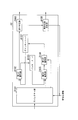
- FIG. 2 is a schematic block diagram showing the configuration of the mobile station device 1a according to the first embodiment of the present invention.
- the mobile station apparatus 1a includes a control signal receiving unit 11a, a transmission apparatus a1, and a transmission antenna 12a.
- the transmission device a1 includes a retransmission control unit a101, a buffer unit a102, a turbo coding unit C1, a modulation unit a103, an FFT (Fast Fourier Transform) unit a104, a mapping unit a105, an IFFT (Inverse Fast Fourier Transform), and an inverse fast Fourier transform.
- the control signal receiving unit 11a is notified of control information from the base station apparatus 1b.
- the control information includes band allocation information used for data transmission, modulation scheme information, and coding information (coding rate (or puncture pattern) and constraint length). However, the control information may include a part of these pieces of information, or may include other information.
- the control signal receiving unit 11a receives a delivery confirmation signal indicating whether or not the data is correctly received by the receiving device of the base station device 1b.
- the delivery confirmation signal includes an ACK (ACKnowledgement) signal or NACK (Negative ACKnowledgement).
- the ACK is a signal notified from the base station device 1b to the mobile station device 1a when the receiving device can correctly receive data.
- NACK is a signal notified from the base station apparatus 1b to the mobile station apparatus 1a when the receiving apparatus cannot receive data correctly, and indicates a retransmission request indicating that the base station apparatus 1b is requested to retransmit data.
- This delivery confirmation signal includes control information (referred to as retransmission control information) for the retransmission signal.
- the control signal receiving unit 11a extracts modulation scheme information and band allocation information from the received control information and retransmission control information, and outputs them to the modulation unit a103 and the mapping unit a105, respectively. In addition, the control signal receiving unit 11a outputs the encoded information extracted from the control information and the retransmission control information, and the delivery confirmation signal to the retransmission control unit 110.
- the retransmission control unit a101 determines whether the delivery confirmation signal input from the control signal receiving unit 11a is ACK or NACK. When it is determined as ACK, the retransmission control unit a101 outputs an initial transmission data input command to the buffer unit a102. In this case, the retransmission control unit a101 outputs the encoded information input from the control signal receiving unit 11a to the turbo encoding unit C1. On the other hand, when it is determined as NACK, the retransmission control unit a101 outputs a retransmission data input command to the buffer unit a102. In this case, the retransmission control unit a101 outputs the encoded information of the retransmission control information input from the control signal receiving unit 11a to the turbo coding unit C1.
- the buffer unit a102 stores the input data bits.
- the buffer unit a102 outputs the next data bit sequence (referred to as initial transmission data bit sequence) of the transmitted data bit sequence in the previous frame to the turbo encoding unit C1.
- initial transmission data bit sequence the next data bit sequence of the transmitted data bit sequence in the previous frame
- turbo encoding unit C1 the buffer unit a102 outputs the same data bit sequence (referred to as a retransmission data bit sequence) as the transmitted data bit sequence in the previous frame to the turbo encoding unit C1.
- the turbo encoding unit C1 generates encoded bits by turbo-encoding the bit string input from the buffer unit a102 based on the encoding information input from the retransmission control unit a101. Bits for cyclic redundancy check (CRC) are added to the encoded bits.
- the turbo encoder C1 outputs the generated encoded bits to the modulator a103. Details of the turbo encoding unit C1 will be described later.
- the modulation unit a103 generates a modulation symbol by modulating the coded bits input from the turbo coding unit C1 with the modulation method indicated by the modulation method information input from the control signal receiving unit 11a.
- the modulation scheme includes, for example, QPSK (Quaternary Phase Shift Keying) and 16QAM (16-ary Quadrature Amplitude Modulation).
- the modulation unit a103 outputs the generated modulation symbol to the FFT unit a104.
- the FFT unit a104 converts the modulation symbol input from the modulation unit a103 from a time domain signal to a frequency domain signal, and outputs the signal to the mapping unit a105.
- the mapping unit a105 arranges (maps) the signal input from the FFT unit a104 in each band based on the band allocation information input from the control signal receiving unit 11a and outputs the signal to the IFFT unit a106.
- the IFFT unit a106 converts the signal input from the mapping unit a105 from a frequency domain to a time domain signal, and outputs the signal to the reference signal multiplexing unit a107.
- the reference signal multiplexing unit a107 generates a reference signal in which waveforms are stored in advance in the transmitting device a1 of the mobile station device 1a and the receiving device b1 of the base station device 1b, and the signal input from the IFFT unit a106 in the time domain. Multiplex. For example, the transmission device a1 may multiplex the reference signal in the frequency domain with the signal before the IFFT unit a106 processes.
- the reference signal multiplexing unit a107 outputs the multiplexed signal to the transmission processing unit a108.
- the transmission processing unit a108 inserts a CP (Cyclic Prefix) into the signal input from the reference signal multiplexing unit a107.
- the transmission processing unit a108 performs D / A (Digital / Analog; digital / analog) conversion on the signal after inserting the CP, and upconverts the signal to a radio frequency.
- the transmission processing unit a108 amplifies the signal after up-conversion to transmission power using PA (Power Amplifier), and transmits it through the transmission antenna 12a.
- PA Power Amplifier
- FIG. 3 is a schematic block diagram showing the configuration of the turbo encoding unit C1 according to the present embodiment.
- the turbo coding unit C1 includes a CRC adding unit C111, an interleaver C112, a coding scheme selecting unit C113, a first coding unit C114, a second coding unit C115, a third coding unit C116, a puncturing unit C117, And a sign bit output unit C118.
- the first encoding unit C114 and the second encoding unit C115 perform encoding with a constraint length of “4”.
- the third encoding unit C116 performs encoding with a constraint length of “3”.
- the constraint length of the third encoding unit C116 is not limited to this constraint length value as long as the constraint length is different from that of the other encoding units.
- the turbo encoding unit C1 may include an encoding unit having a constraint length different from that of other encoding units.
- the CRC adding unit C111 receives a bit string (initial transmission data bit string or retransmission data bit string) from the buffer unit a102.
- the CRC adding unit C111 adds a cyclic redundancy check bit to the input bit string, and outputs the bit sequence to the interleaver C112 and the first encoding unit C114.
- the interleaver C112 rearranges (interleaves) the bit string input from the CRC adding unit C111 in a predetermined order and outputs the bit sequence to the encoding scheme selecting unit C113.
- the encoding scheme selection unit C113 outputs the bit string input from the interleaver C112 to the encoding unit corresponding to the constraint length indicated by the encoding information input from the retransmission control unit a101. Specifically, the coding scheme selection unit C113 outputs a bit string to the third coding unit C116 when the constraint length indicated by the encoding information is “3”, while the constraint length indicated by the encoding information. Is “4”, a bit string is output to the second encoding unit C115.
- the first encoding unit C114 outputs the systematic bits that are the input bit string to the code bit output unit C118. Also, the first encoding unit C114 encodes the bits input from the CRC adding unit C111 using an RSC (recursive systematic convolution) code having a constraint length of “4”. The first encoding unit C114 outputs the parity bits generated by encoding to the puncturing unit C117. The second encoding unit C115 encodes the bits input from the encoding method selection unit C113 using an RSC code having a constraint length of “4”. The second encoding unit C115 outputs the parity bits generated by encoding to the puncturing unit C117.
- RSC recursive systematic convolution
- the third encoding unit C116 encodes the bits input from the encoding method selection unit C113 using an RSC code having a constraint length of “3”.
- the third encoding unit C116 outputs the parity bits generated by encoding to the puncture unit C117.
- the puncture unit C117 stores in advance puncture information in which a coding rate and a puncture pattern are associated with each other.
- the puncture unit C117 selects a puncture pattern from the puncture information based on the coding rate indicated by the coding information input from the retransmission control unit a101.
- the puncturing unit C117 punctures the parity bits input from the first encoding unit C114 and the second encoding unit C115 or the third encoding unit C116 with the selected puncture pattern.
- the puncturing unit C117 outputs the punctured parity bits to the code bit output unit C118.
- the code bit output unit C118 generates encoded bits by concatenating the systematic bits input from the first encoding unit C114 and the parity bits input from the puncture unit C117 according to a predetermined concatenation order. To do. Specifically, the code bit output unit C118 includes systematic bits (referred to as a bit string B11), a parity bit part (referred to as a bit string B12) of the first encoding unit C114, the second encoding unit C115, or the third encoding. Concatenation is performed in the order of the parity bit part (bit string B13) of the part C116. The sign bit output unit C118 outputs the generated coded bits.
- the constraint length indicated by the encoded information is “4”.
- the constraint length indicated by the encoded information is “3”.
- the configuration of the turbo coding unit C1 the initial transmission data bit string output via the CRC adding unit C111, the interleaver C112, and the coding method selection unit C113 is encoded by the second coding unit C115 ( The constraint length is “4”) and punctured by the puncture unit C117.
- the retransmission data bit string output via the CRC adding unit C111, the interleaver C112, and the encoding scheme selecting unit C113 is encoded (constraint length “3”) by the third encoding unit C116, and the puncturing unit C117. Punctured. That is, the turbo encoding unit C1 has a constraint length “3” (encoding unit C116) and a constraint length “4” (encoding unit) different from the constraint length “4” (encoding units C114 and C115) used in the initial transmission. 117) is used together, and bits are encoded to generate a retransmission signal.
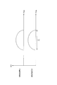
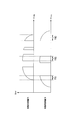
- FIG. 4 is a schematic diagram illustrating a configuration of the first encoding unit C114 according to the present embodiment.
- the first encoding unit C114 includes adders C1141, C1143, C1146, C1147, and delay circuits C1142, C1144, C1145.
- Adders C1141, C1143, C1146, and C1147 add the input bits.
- the delay circuits C1142, C1144, and C1145 delay the input bit by 1 bit and output it.
- the configuration of the second encoding unit C115 is obtained by removing the output of systematic bits from the configuration of the first encoding unit C114.
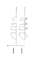
- the third encoding unit C116 includes adders C1161, C1163, C1165, and delay circuits C1162, C1164. Adders C1161, C1163, and C1165 add the input bits.
- the delay circuits C1162 and C1164 delay the input bits by one bit and output them.
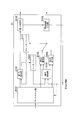
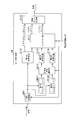
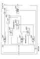
- FIG. 6 is a schematic block diagram illustrating the configuration of the base station device 1b according to the present embodiment.
- the base station apparatus 1b includes a reception antenna 11b, a reception apparatus b1, a control information generation unit 12b, and a delivery confirmation signal transmission unit 13b.
- the reception device b1 includes a reception processing unit b101, a reference signal separation unit b102, a propagation path estimation unit b103, an FFT unit b104, a demapping unit b105, a soft canceller unit b106, an equalization unit b107, a signal addition unit b108, an IFFT unit b109, A demodulator b110, a decoder D1, a symbol generator b111, an FFT unit b112, and a replica generator b113 are included.
- the reception processing unit b101 receives a signal transmitted from the mobile station device 1a via the reception antenna 11b.
- the reception processing unit b101 down-converts the received signal to a baseband frequency and performs A / D (Analog / Digital) conversion.
- the reception processing unit b101 removes the CP from the signal after A / D conversion, and outputs the signal to the reference signal separation unit b102.
- the reference signal separation unit b102 divides the signal input from the reception processing unit b101 into a reference signal and a signal other than the reference signal.
- the reference signal separation unit b102 outputs the divided reference signal to the propagation path estimation unit b103, and outputs a signal other than the reference signal to the FFT unit b104.
- the propagation path estimation unit b103 estimates the frequency response of the propagation path (referred to as propagation path characteristics) based on the reference signal input from the reference signal separation unit b102 and the reference signal stored in advance.
- the propagation path estimation unit b103 outputs the propagation path characteristic information indicating the estimated propagation path characteristics to the control information generation unit 12b, the equalization unit b107, and the replica generation unit b113.
- the control information generation section 12b Based on the propagation path characteristics indicated by the information input from the propagation path estimation section b103, the control information generation section 12b assigns a band to each mobile station apparatus 1a, a modulation scheme, a coding rate (or puncture pattern), and a constraint. Determine the length.
- the control information generating unit 12b generates band allocation information indicating the determined band allocation, modulation scheme information indicating the modulation scheme, encoding information indicating the coding rate (or puncture pattern), and constraint length.
- the control information generation unit 12b notifies the mobile station apparatus 1a of the control information including the generated band allocation information, modulation scheme information, and encoding information.
- the control information generation unit 12b outputs the generated band allocation information to the demapping unit b105.
- the control information generation unit 12b outputs the generated modulation scheme information to the demodulation unit b110 and the symbol generation unit b111.
- the control information generation unit 12b outputs the generated encoded information to the decoding unit D1.
- the FFT unit b104 converts the signal input from the reference signal separation unit b102 from a time domain signal to a frequency domain signal, and outputs the signal to the demapping unit b105.
- the demapping unit b105 extracts (demappings) the signal input from the FFT unit b104 from each band based on the band allocation information input from the control information generation unit 12b, and outputs the extracted signal to the soft canceller unit b106.
- the demapping unit b105 performs demapping based on the band allocation information.
- the soft canceller unit b106 receives (feeds back) a replica signal (soft replica) of a desired signal generated from the decoded data bits from the replica generation unit b113.
- the soft canceller unit b106 stores the signal input from the demapping unit b105, and subtracts the input soft replica from the stored signal.
- the soft canceller unit b106 outputs the subtracted signal to the equalization unit b107.
- the signal input from the demapping unit b105 is output to the equalizing unit b107 as it is.
- the equalization unit b107 performs equalization processing on the signal input from the soft canceller unit b106 based on the channel characteristic information input from the channel estimation unit b103. This equalization processing is processing for compensating for distortion due to a radio propagation path by multiplying a weight based on a MMSE (Minimum Mean Square Error) standard, a ZF (Zero Forcing) weight, or the like.
- the equalization unit b107 outputs the equalized signal to the signal addition unit b108.
- the signal adder b108 receives a symbol frequency domain replica signal generated from the decoded data bits from the FFT unit b112.
- the signal addition unit b108 adds the input replica signal to the signal input from the equalization unit b107.
- the signal adder b108 outputs the added signal to the IFFT unit b109.
- the IFFT unit b109 converts the signal input from the signal addition unit b108 from a frequency domain to a time domain signal and outputs the signal to the demodulation unit b110. Based on the modulation scheme information input from the control information generation unit 12b, the demodulation unit b110 demodulates the signal input from the IFFT unit b109 to convert it into encoded bits. However, when the decoding unit D1 determines the modulation scheme information for the retransmission signal, the demodulation unit b110 demodulates based on the modulation scheme information. The demodulator b110 outputs the demodulated encoded bits to the decoder D1.
- the decoding unit D1 decodes the encoded bits input from the demodulation unit b110 based on the encoded information input from the control information generation unit 12b. However, when the decoding unit D1 determines the encoding information for the retransmission signal, the decoding unit D1 decodes the encoded bit of the retransmission signal based on the determined encoding information. The decoding unit D1 checks whether or not the data bits have been correctly acquired based on the cyclic redundancy check bits included in the decoded bit string. The decoding unit D1 determines retransmission control information based on the inspection result after performing feedback to the soft canceller an arbitrary number of times.
- the decoding unit D1 outputs the data bits excluding the cyclic redundancy check bits and the retransmission control information to the external device.
- the error correction decoding result of the encoded bit by the decoding unit D1 is an error
- a bit punctured again with respect to the decoded bit is output to the symbol generation unit b111.
- the decoding unit D1 outputs a transmission command and retransmission control information for transmitting a delivery confirmation signal to the delivery confirmation signal transmission unit 13b based on the test result after feedback to the soft canceller any number of times or a predetermined number of times. Details of the decoding unit D1 will be described later.
- the symbol generation unit b111 generates a symbol replica by performing the same processing (modulation) as the modulation unit a103 of the mobile station apparatus 1a based on the modulation scheme information input from the control information generation unit 12b. However, when the decoding unit D1 determines the modulation scheme information for the retransmission signal, the symbol generation unit b111 modulates based on the modulation scheme information.
- the symbol generation unit b111 outputs the generated symbol replica to the FFT unit b112.
- the FFT unit b112 converts the symbol replica input from the symbol generation unit b111 from a time domain to a frequency domain signal (replica signal), and outputs the signal to the replica generation unit b113 and the signal addition unit b108.
- the replica generation unit b113 generates a soft replica by multiplying the propagation path characteristic information input from the propagation path estimation unit b103 by the replica signal input from the FFT unit b112.
- the replica generation unit b113 outputs the generated soft replica to the soft canceller unit b106.
- the delivery confirmation signal transmission unit 13b notifies the mobile station apparatus 1a of ACK or NACK as a delivery confirmation signal in accordance with the transmission command input from the decoding unit D1.
- the delivery confirmation signal transmitting unit 13b notifies the delivery confirmation signal including the retransmission control information input from the decoding unit D1.
- the delivery confirmation signal transmission part 13b may notify NACK and retransmission control information simultaneously, and may notify separately at a different timing.
- the inter-symbol interference is obtained by using the soft canceller and the equalizer in the single carrier as the MAP detector and performing the reception process for the repetition process of the MAP detector and the decoder.
- turbo equalization configuration is not limited to this example.
- the present invention can be applied to a case where an intersymbol interference or intercarrier interference is canceled by a turbo equalization reception process in which a MAP detector in a multicarrier is a soft canceller and the MAP detector and decoder are repeated.
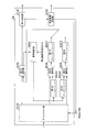
- FIG. 7 is a schematic block diagram showing the configuration of the decoding unit D1 according to this embodiment.
- the decoding unit D1 includes a depuncture unit D101, a first decoding unit D102, an interleaver D103, a decoding control unit D104, a second decoding unit D105, a third decoding unit D106, a deinterleaver D107, an error determination. Part D108 and retransmission control determining part D109.
- the depuncture unit D101 and the decoding control unit D104 receive the encoded information from the control information generation unit 12b and the retransmission control determination unit D109.
- the depuncture unit D101 and the decoding control unit D104 select the encoding information from the retransmission control determination unit D109 when performing processing on the retransmission signal, and the encoding information from the control information generation unit 12b otherwise. Select to process.
- the depuncture unit D101 divides the encoded bits input from the demodulation unit b110 according to the same concatenation order used by the code bit output unit C118 of the turbo encoding unit C1. Specifically, the depuncture unit D101 divides into the above bit strings B11, B12, and B13. The depuncture unit D101 stores the same puncture pattern information as that stored by the puncture unit C117. The depuncture unit D101 selects a puncture pattern from the puncture information based on the selected encoding information. The depuncture unit D101 inserts (depunctures) a bit indicating “0” into a portion punctured with the selected puncture pattern for the divided bit strings B12 and B13.
- the depuncture unit D101 outputs the divided bit string B11 (referred to as systematic bit 11) and the depunctured bit string B12 (referred to as parity bit 21) to the first decoding unit D102. Further, the depuncture unit D101 outputs the depunctured bit string B13 (referred to as the parity bit 22) to a decoding unit corresponding to the constraint length indicated by the selected encoded information. Specifically, when the constraint length indicated by the encoding information is “3”, the depuncture unit D101 outputs the parity bit 22 to the third decoding unit D106, while the constraint length indicated by the encoding information is “ In the case of “4”, the parity bit 22 is output to the second decoding unit D105.
- the first decoding unit D102 stores the parity bit 1 input from the depuncture unit D101.
- the first decoding unit D102 performs decoding processing based on MAP (Maximum A Positive Probability) estimation using the stored parity bit 21 and the bit string (systematic bit 12) input from the deinterleaver D107. Accordingly, the first decoding unit D102 performs error correction processing on desired data bits (referred to as systematic bits 13). However, in the first process, the first decoding unit D102 performs a decoding process by MAP estimation using the stored parity bit 21 and systematic bit 11.
- the first decoding unit D102 outputs the decoded systematic bit 13 to the error determination unit D108 when the predetermined number of decoding processes are performed, and performs the decoding when the predetermined number of decoding processes are not performed.
- the systematic bit 13 is output to the interleaver D103.
- the interleaver D103 rearranges (interleaves) the systematic bits 13 input from the first decoding unit D102 in a predetermined order and outputs the rearranged bit string to the decoding control unit D104. Called systematic bit 14).
- the predetermined order is the same as the order used by the interleaver C112 of the turbo encoding unit C1.
- the decoding control unit D104 outputs the systematic bit 14 input from the interleaver D103 to a decoding unit corresponding to the constraint length indicated by the selected encoding information.
- the decoding control unit D104 outputs the systematic bit 14 to the third decoding unit D106, while the constraint length indicated by the encoding information is In the case of “4”, the systematic bit 14 is output to the second decoding unit D105.
- the second decoding unit D105 stores the parity bit 22 input from the depuncture unit D101.
- the second decoding unit D105 performs a decoding process based on MAP estimation using the stored parity bit 22 and the systematic bit 14 input from the interleaver D103. Accordingly, the second decoding unit D105 performs error correction processing on the desired interleaved data bit (referred to as systematic bit 15).
- the second decoding unit D105 performs a decoding process of the constraint length “4”.
- the second decoding unit D105 outputs the decoded systematic bit 15 to the deinterleaver D107.
- the third decoding unit D106 stores the parity bit 22 input from the depuncture unit D101.
- the third decoding unit D106 uses the stored parity bit 22 and the systematic bit 14 input from the interleaver D103 to perform decoding processing based on MAP estimation, thereby interleaving desired data bits (systematic bits). 16) is subjected to error correction processing.
- the third decoding unit D106 performs a decoding process of the constraint length “3”.
- the third decoding unit D106 outputs the decoded systematic bit 16 to the deinterleaver D107.
- FIG. 7 the case where the deinterleaver D107 is connected to the second decoding unit D105 is described. However, the deinterleaver D107 is either the second decoding unit D105 or the third decoding unit D106. The connection can be switched to. Specifically, the deinterleaver D107 is connected to a decoding unit corresponding to the constraint length indicated by the encoding information.
- the deinterleaver D107 rearranges the systematic bits 15 input from the second decoding unit D105 or the systematic bits 16 input from the third decoding unit D106 in a predetermined order, so that the first decoding unit Output to D102 (the bit string after the rearrangement is systematic bit 12).
- the predetermined order is an order reverse to the order used by the interleaver C112.
- the systematic bit 12 input from the deinterleaver D107 is decoded by the first decoding unit D102, interleaved by the interleaver D103, and decoded by the second decoding unit D105 or the third decoding unit D106. Is done.
- the decoded bit string is then interleaved by the deinterleaver D107 and input to the first decoding unit D102.
- the systematic bit 12 repeats these processes a predetermined number of times, and outputs it to the error determination unit D108.
- the decoding unit D1 can perform decoding by switching between the decoding unit and the deinterleaver even when an encoded retransmission signal is received with a constraint length different from the constraint length of the encoded bits received in the initial transmission. it can.
- the error determination unit D108 extracts a cyclic redundancy check bit from the systematic bit 13 input from the first decoding unit D102, and checks whether or not the data bit has been correctly acquired based on this bit. If it is determined that the data has been correctly acquired (no error), the error determination unit D108 outputs the acquired data bits to an external device. In this case, the error determination unit D108 outputs a transmission command indicating transmission of ACK to the delivery confirmation signal transmission unit 13b. On the other hand, when it is determined that the data cannot be acquired correctly (there is an error), the error determination unit D108 outputs the acquired data bits to the symbol generation unit b111.
- the error determination unit D108 counts the number of times it is determined that acquisition is not possible, that is, the number of times equalization processing has been performed (referred to as the number of equalizations). If the error determination unit D108 determines that the data cannot be correctly acquired when the number of equalizations exceeds a predetermined value, the error determination unit D108 outputs information indicating that retransmission is requested to the retransmission control determination unit D109.
- the retransmission control determination unit D109 determines that the constraint length is “3” when information indicating that retransmission is requested is input. This restraint length is shorter than the initially sent restraint length “4”. In this case, in the communication system, in retransmission, encoding and decoding are performed with a constraint length shorter than the constraint length of the initial transmission (previous transmission) that could not be received correctly.
- the retransmission control determination unit D109 generates retransmission control information including encoded information indicating the determined constraint length.
- the retransmission control determination unit D109 outputs the generated retransmission control information and a transmission command indicating transmission of NACK to the delivery confirmation signal transmission unit 13b.
- retransmission control determining section D110 outputs the encoded information included in the generated retransmission control information to depuncture section D101 and decoding control section D104.
- retransmission control determining section D109 may determine coding information indicating band allocation information, modulation scheme information, and coding rate (or puncture pattern) based on propagation path characteristic information. Then, retransmission control information including these pieces of information is generated.
- the error determination unit D108 has been described as an example in which the bit output from the first decoding unit D102 after the turbo decoding is repeated an arbitrary number of times or a predetermined number of times, the turbo decoding is performed an arbitrary number of times or a predetermined number of times. May be output from the second decoding unit D105 or the third decoding unit D106 after the number of repetitions.
- FIG. 31 is a schematic block diagram showing the configuration of the decoding unit E1 according to the conventional technique.
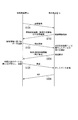
- FIG. 8 is a sequence diagram showing an example of the operation of the communication system according to the present embodiment.
- this figure is an example of the uplink communication from the mobile station apparatus 1a to the base station apparatus 1b.
- This figure is an example in which an error is detected in the first transmission and no error is detected in the second transmission (first retransmission).
- Step S101 The mobile station apparatus 1a transmits a reference signal to the base station apparatus 1b.
- This reference signal may be multiplexed with a data signal, or may be a signal in which only the reference signal is transmitted without multiplexing. Thereafter, the process proceeds to step S102.
- Step S102 The base station apparatus 1b receives the reference signal transmitted in step S101, and estimates the propagation path characteristic from the received reference signal.
- the base station apparatus 1b determines control information (including band allocation information, modulation scheme information, and coding information) for the mobile station apparatus 1a based on the estimated propagation path characteristics.
- the base station device 1b transmits the determined control information to the mobile station device. Thereafter, the process proceeds to step S103.
- Step S103 The mobile station apparatus 1a receives the control information transmitted in step S103, and transmits a signal obtained by encoding and modulating data bits based on the received control information (initial transmission; initial transmission). Thereafter, the process proceeds to step S104.
- Step S104 The base station apparatus 1b receives the signal transmitted in step S103, and demodulates and decodes the received signal based on the control information notified in S102. The base station apparatus 1b performs a cyclic redundancy check on the decoded data bit to check whether the data bit has been correctly acquired. In the example of FIG. 8, it is determined that the data bits cannot be acquired correctly, that is, an error is detected.
- the base station apparatus 1b transmits a NACK signal and retransmission control information (including band allocation information, modulation scheme information, and encoding information) as a delivery confirmation signal. Thereafter, the process proceeds to step S105. If it is determined that the data bits have been correctly acquired, the base station apparatus 1b transmits an ACK and completes the transmission of the data bits.
- retransmission control information including band allocation information, modulation scheme information, and encoding information
- Step S105 The mobile station apparatus 1a receives the delivery confirmation signal transmitted in step S104. Based on the received delivery confirmation signal, the mobile station device 1a encodes and modulates the same data bits as the data bits transmitted in step S103, and generates a retransmission signal. Here, the constraint length used for retransmission encoding is different from the constraint length used for encoding in step S103.
- the mobile station apparatus 1a transmits the generated retransmission signal, that is, retransmits the data bit signal. Thereafter, the process proceeds to step S106.
- the base station apparatus 1b receives the signal transmitted in step S105, and demodulates and decodes it using the received retransmission signal and initial transmission signal.
- the base station apparatus 1b performs a cyclic redundancy check on the decoded data bit to check whether the data bit has been correctly acquired. In the example of FIG. 8, it is determined that the data bits have been correctly acquired. In this case, the base station apparatus 1b transmits an ACK signal as a delivery confirmation signal.
- the mobile station apparatus 1a generates a retransmission signal by encoding bits with a constraint length different from the constraint length used in the previous (initial transmission) transmission, and the generated retransmission.
- the receiving device b1 repeats equalization using bits of the retransmission signal, which are bits decoded with a constraint length different from the constraint length used in the previous (initial transmission) reception.
- the communication system can improve communication quality. For example, by using a constraint length shorter than the constraint length used in the previous communication, turbo equalization can be converged and communication quality can be improved in the communication system.
- the turbo equalization when the turbo equalization is retransmitted without converging, the turbo equalization can be converged and the communication quality can be improved. Therefore, in the communication system, it is possible to improve the error rate characteristic at the time of retransmission, and to prevent a decrease in cell throughput.
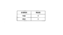
- ⁇ Modification 1> In the first embodiment, the case has been described in which encoded information indicating the constraint length is transmitted from the base station apparatus 1b to the mobile station apparatus 1a. In the first modification, a case will be described in the communication system where the constraint length is selected according to whether the delivery confirmation signal is ACK or NACK. In this modification, the encoding scheme selection unit C113 and the retransmission control determination unit D109 store a constraint length table (FIG. 9) in advance.
- FIG. 9 is a schematic diagram illustrating an example of a constraint length table according to the first modification.
- the constraint length table has a column for each item of the transmission type indicating whether the transmission is initial transmission or retransmission, and the constraint length.
- the constraint length table is two-dimensional tabular data composed of rows and columns in which information indicating the constraint length is stored for each transmission type. In this figure, for example, when the transmission type is “initial transmission”, the constraint length “4” is associated, and when the transmission type is “retransmission”, the constraint length “3” is associated.
- the encoding scheme selection unit C113 determines whether the transmission type is initial transmission or retransmission by determining whether the delivery confirmation signal is ACK or NACK. In the case of ACK (initial transmission), the encoding scheme selection unit C113 outputs a bit string to the second encoding unit C115 whose constraint length is “4”. On the other hand, in the case of NACK (retransmission), the encoding scheme selection unit C113 outputs a bit string to the third encoding unit C116 whose constraint length is “3”. As described above, according to the first modification, the constraint length can be changed without transmitting encoded information indicating the constraint length from the base station device 1b to the mobile station device 1a, thereby improving transmission efficiency. be able to.
- ⁇ Modification 2> In the first embodiment, the case has been described in which the constraint length is determined according to retransmission or initial transmission. In the second modification, the case where the constraint length is selected according to the number of transmissions in the communication system will be described.
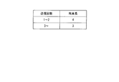
- the encoding scheme selection unit C113 and the retransmission control determination unit D109 according to the second modification store a constraint length table (FIG. 10) in advance.
- FIG. 10 is a schematic diagram illustrating an example of a constraint length table according to the second modification.
- the constraint length table has columns for each item of the number of transmissions and the constraint length.
- the constraint length table is two-dimensional tabular data composed of rows and columns in which information indicating the constraint length is stored for each transmission count. In this figure, for example, when the number of transmissions is “1” or more and “2” or less, the constraint length “4” is associated, and when the number of transmissions is “3” or more, the constraint length “3” is associated. It has been.
- the encoding method selection unit C113 and the retransmission control determination unit D109 count the number of transmissions.
- the encoding scheme selection unit C113 and the retransmission control determination unit D109 select a constraint length corresponding to the counted number of transmissions based on a constraint length table stored in advance. Only the retransmission control determining unit D109 may store the constraint length table and select the constraint length based on the constraint length table. In this case, retransmission control determining section D109 transmits encoded information indicating the selected constraint length to mobile station apparatus 1a.
- communications with different constraint lengths are not limited to initial transmission and retransmission.
- the encoding scheme selection unit C113 and the retransmission control determination unit D109 are different between the first retransmission (transmission count “2”) and the second retransmission (transmission count “3”).
- the coding length may be selected. That is, the transmission before the constraint lengths are different is not limited to the initial transmission, and may be retransmission.
- turbo coding (first coding unit C114 and second coding unit C115) with a constraint length of “4” is performed in the first transmission, and part of the retransmission is performed.
- turbo encoding (first encoding unit C114 and third encoding unit C116) with a constraint length “3” is performed
- the decoding method is not limited to the above.
- the code control unit D104 may switch the output destination according to the number of turbo decoding iterations. A modification is shown below. In FIG. 7, systematic bits that are output from the first decoding unit D102 are rearranged by the interleave D103, and the rearranged bits are input to the decoding control unit 104.
- the decoding control unit D104 inputs the systematic bits input from the interleaver D103 to the second decoding unit D105.
- the decoding result in the second decoding unit D105 is input to the first decoding unit D102 via the deinterleaver D107.
- the initial transmission is the same as the conventional turbo decoding by the first decoding unit D102 and the second decoding unit D105.
- the decoding control unit D104 inputs the systematic bits input from the interleaver D103 to the third decoding unit D106.
- the decoding result of the third decoding unit D106 is input to the first decoding unit D102 via the deinterleaver D107.
- the decoding result in the first decoding unit D102 is again output to the decoding control unit D104 via the interleaver D103, but the decoding control unit D104 changes the decoding unit to be output.
- the decoding control unit D104 outputs the input bits to the second decoding unit D105 instead of the third decoding unit D106 used in the first decoding process.
- the second decoding unit D105 decoding is performed using the parity bit transmitted in the initial transmission, and the result is output to the deinterleaver D107.
- the deinterleaver D107 performs rearrangement of processing reverse to that of the interleaver, and outputs the rearranged bits to the first decoding unit D102.
- the decoding process is performed by repeating this process. Therefore, in the decoding unit D1, the third decoding unit D106 is used in odd-numbered processes such as the first, third, and fifth iterations of turbo decoding, and even numbers such as the second, fourth, and sixth times are used.
- the second decoding unit D105 is used in the processing of the first time.
- the parity bits received in the initial transmission and the retransmission can be used as in the case where the constraint length is not changed between the initial transmission and the retransmission.
- the error rate characteristic can be improved and the cell throughput can be prevented from decreasing.
- the configuration of the decoding unit D1 is not limited to this, and may be the configuration of the decoding unit D2 as shown in FIG.
- FIG. 11 is a schematic diagram illustrating a configuration of the decoding unit D2 according to the fourth modification.
- the second decoding unit D105 and the third decoding unit D106 are connected in series.
- the systematic bit 14 output from the interleaver D103 is decoded by the second decoding unit D105 when the constraint length is “4”, and the third decoding unit when the constraint length is “3”.
- the data is decoded at D106 and output to the deinterleaver D107.
- the decoding unit D2 can perform communication with the constraint length changed without the code control unit D104, and the circuit and program can be simplified compared to the decoding unit D1.
- the first transmission signal is decoded by the first decoding unit D102, and the decoding result is used as prior information of the second decoding unit D105 or the third decoding unit D106.
- the decoding unit D1 may be configured to first decode the retransmission signal and use the decoding result as prior information of the first decoding unit D102.
- the communication system performs rearrangement of the bit order using rearrangement different from the rearrangement used in the previous transmission.
- a case will be described in which the communication system selects the constraint length depending on whether the delivery confirmation signal is ACK or NACK.
- the present invention is not limited to this, and in the communication system, as in the first embodiment, the base station device 1b determines the constraint length and transmits the encoded information indicating the determined constraint length to the mobile station device 1a. May be.
- the mobile station devices 2A and 3A in FIG. 1 are referred to as a mobile station device 2a
- the base station device 1B is referred to as a base station device 2b.
- FIG. 12 is a schematic block diagram showing the configuration of the mobile station device 2a according to the second embodiment of the present invention.
- the turbo coding unit C3 of the transmission apparatus a2 is different.
- other components control signal receiving unit 11a, transmission antenna 12a, retransmission control unit a101, buffer unit a102, modulation unit a103, FFT unit a104, mapping unit a105, IFFT unit a106, reference signal multiplexing unit a107, and transmission
- the function of the processing unit a108 is the same as that of the first embodiment. A description of the same functions as those in the first embodiment is omitted.
- FIG. 13 is a schematic block diagram showing the configuration of the turbo encoding unit C3 according to this embodiment.
- the turbo encoder C3 (FIG. 13) according to the present embodiment is compared with the turbo encoder C1 (FIG. 3) according to the first embodiment, the first interleaver C3121, the second interleaver C3122, and The encoding method selection unit C313 is different.
- the turbo coding unit C1 is a CRC adding unit C111, a first coding unit C114, a second coding unit C115, a third coding unit C116, a puncturing unit C117, and a code bit output.
- Part C118 has the same function as in the first embodiment. A description of the same functions as those in the first embodiment is omitted.
- the first interleaver C3121 rearranges (interleaves) the bit string input from the CRC adding unit C111 in a predetermined order.
- the first interleaver C3121 receives a delivery confirmation signal from the retransmission control unit a101.
- the first interleaver C3121 determines whether the input acknowledgment signal is ACK or NACK. That is, the first interleaver C 3121 determines whether the bit string to be processed is the first transmission or the retransmission.
- the first interleaver C3121 outputs the rearranged bit string to the encoding scheme selection unit C113.
- the first interleaver C3121 outputs the rearranged bit string to the second interleaver C3122.
- the second interleaver C3122 rearranges (interleaves) the bit string input from the first interleaver C3121 in a predetermined order and outputs the bit sequence to the encoding scheme selection unit C113.
- the second interleaver C3122 rearranges the bit strings so that they are in a different order from the bit strings output by the CRC adding unit C11 and the first interleaver C3121.
- the encoding scheme selection unit C313 receives the delivery confirmation signal from the retransmission control unit a101. The encoding scheme selection unit C313 determines whether the input delivery confirmation signal is ACK or NACK. If it is determined that the delivery confirmation signal is ACK, the encoding scheme selection unit C313 outputs the bit string input from the first interleaver C3121 to the second encoding unit C115. On the other hand, when it is determined that the delivery confirmation signal is NACK, the encoding scheme selection unit C313 outputs the bit string input from the second interleaver C3122 to the third encoding unit C116.
- the bit string output from the first interleaver C3121 is encoded by the second encoding unit C115.
- the bit string output from the first interleaver C3121 is interleaved by the second interleaver C3122 and encoded by the third encoding unit C116.
- FIG. 14 is a schematic block diagram showing the configuration of the base station device 2b according to this embodiment.
- the turbo decoding unit D3 of the receiving apparatus b2 is different.
- reception antenna 11b reception antenna 11b, control information generation unit 12b, delivery confirmation signal transmission unit 13b, reception processing unit b101, reference signal separation unit b102, propagation path estimation unit b103, FFT unit b104, demapping unit b105
- the functions of the soft canceller unit b106, equalization unit b107, IFFT unit b109, demodulation unit b110, symbol generation unit b111, FFT unit b112, and replica generation unit b113 are the same as those in the first embodiment. A description of the same functions as those in the first embodiment is omitted.
- FIG. 15 is a schematic block diagram showing the configuration of the decoding unit D3 according to this embodiment. Comparing the decoding unit D3 (FIG. 15) according to the present embodiment and the decoding unit D1 (FIG. 7) according to the first embodiment, the second decoding unit D305, the first interleaver D3031, the second interleaver The leaver D3032, the first deinterleaver D3071 and the second deinterleaver D3072 are different. However, the functions of other components (depuncture unit D101, first decoding unit D102, decoding control unit D104, third decoding unit D106, error determination unit D108, and retransmission control determination unit D109) are the same as those in the first embodiment. The form is the same. A description of the same functions as those in the first embodiment is omitted.
- the first interleaver D3031 rearranges the systematic bits 13 input from the first decoding unit D102 in a predetermined order (interleaved), and outputs the rearranged bits to the second decoding unit D305 (rearrangement).
- the subsequent bit string is referred to as systematic bit 14).
- the predetermined order is the same as the order used by the first interleaver C3121 of the turbo encoding unit C3.
- the second decoding unit D305 stores the parity bit 22 input from the depuncture unit D101.
- the second decoding unit D305 performs decoding processing based on MAP estimation using the stored parity bit 22 and the systematic bit 14 input from the first interleaver D3031.
- the second decoding unit D305 performs error correction on the desired interleaved data bit (referred to as systematic bit 15).
- the second decoding unit D305 receives the delivery confirmation signal from the retransmission control determination unit D109.
- the second decoding unit D305 determines whether the input delivery confirmation signal is ACK or NACK. When determining that the delivery confirmation signal is ACK, the second decoding unit D305 outputs the systematic bit 15 subjected to error correction to the first deinterleaver D3071.
- the second decoding unit D305 when it is determined that the delivery confirmation signal is NACK, the second decoding unit D305 outputs the systematic bit 15 subjected to error correction to the second interleaver D3032. In this case, the second decoding unit D305 switches the switch so as to be connected to the second interleaver D3032.
- the second interleaver D3032 rearranges the systematic bits 15 input from the second decoding unit D305 in a predetermined order (interleaved), and outputs the rearranged bits to the third decoding unit D106 (rearrangement).
- the subsequent bit string is called systematic bit 17).
- the predetermined order is the same as the order used by the second interleaver C3122 of the turbo encoding unit C3.
- the systematic bit 17 is decoded by the third decoding unit D106 and output to the second deinterleaver D3072.
- the second deinterleaver D3072 rearranges the bit sequence output from the third decoding unit D106 in a predetermined order and outputs the rearranged bit sequence to the first deinterleaver D3071 (the rearranged bit sequence is Systematic bit 18).
- the predetermined order is an order opposite to the order used by the second interleaver D3032.
- the first deinterleaver D3071 rearranges the systematic bit 15 input from the second decoding unit D305 or the systematic bit 18 input from the second deinterleaver D3072 in a predetermined order, and 1 to the decoding unit D102 (the rearranged bit string is the systematic bit 12).
- the predetermined order is an order opposite to the order used by the first interleaver D3031.
- the bit string output from the second decoding unit D305 is output to the first deinterleaver D3071.
- the bit string output from the second decoding unit D305 is interleaved by the second interleaver D3032 and decoded by the third decoding unit D106. Thereafter, the decoded bit string is deinterleaved by the second deinterleaver D3072 and output to the first deinterleaver D3071.
- the transmission device a2 reorders and encodes the bit sequence in an arrangement order different from the arrangement order used in the previous (initial transmission) transmission, and the reception device b2 ) Are rearranged and decoded in a different order from the order used for reception.
- the communication system can converge turbo equalization and improve communication quality. Therefore, in the communication system, it is possible to improve the error rate characteristic at the time of retransmission, and to prevent a decrease in cell throughput.
- communication in which the bit order is different is not limited to initial transmission and retransmission.
- the first interleaver C3121, the encoding scheme selection unit C113, and the second decoding unit D305 are different between the first retransmission (transmission count “2”) and the second retransmission (transmission count “3”).
- the output destination may be selected. That is, the transmission before the bit arrangement order is different is not limited to the initial transmission, and may be retransmission.
- the configurations of the turbo coding unit C3 and the decoding unit D3 are not limited to this, and the bit string input to the coding method selection unit C113 may be different depending on the type of acknowledgment signal (ACK or NACK). Good.
- the predetermined order used by the first interleaver C3121 and the second interleaver C3122 may be the same order or different orders.
- cord part C4 and the decoding part D4 as shown in FIG. 16, FIG. 17 may be sufficient.
- FIG. 16 is a schematic block diagram illustrating a configuration of a turbo encoding unit C4 according to the fifth modification.
- the turbo coding unit C4 (FIG. 16) according to the present modification is compared with the turbo coding unit C3 (FIG. 13) according to the second embodiment, the CRC adding unit C411 and the first interleaver C4121 are different.
- the functions of other components are the same as those in the first embodiment. A description of the same functions as those in the first embodiment is omitted.
- the CRC adding unit C411 receives a bit string (initial transmission data bit string or retransmission data bit string) from the buffer unit a102.
- the CRC adding unit C411 adds bits for cyclic redundancy check to the input bit string, and outputs the result to the first encoding unit C114.
- the CRC adding unit C411 receives the delivery confirmation signal from the retransmission control unit a101.
- the CRC adding unit C411 determines whether the input delivery confirmation signal is ACK or NACK. If it is determined that the delivery confirmation signal is ACK, the CRC adding unit C411 outputs the rearranged bit string to the first interleaver C4121.
- the CRC adding unit C411 when it is determined that the delivery confirmation signal is NACK, the CRC adding unit C411 outputs the rearranged bit string to the second interleaver C3122.
- the first interleaver C4121 rearranges (interleaves) the bit string input from the CRC adding unit C411 in a predetermined order and outputs the bit sequence to the encoding scheme selection unit C313.
- FIG. 17 is a schematic block diagram illustrating a configuration of the decoding unit D4 according to the fifth modification.
- the code control unit D404 and the second decoding unit D105 are different.
- the functions of other components are the same as in the second embodiment.
- a description of the same functions as those in the second embodiment is omitted.
- the function of the second decoding unit D105 is the same as that of the first embodiment, and a description thereof will be omitted.
- the code control unit D404 receives the delivery confirmation signal from the retransmission control determination unit D111.
- the code control unit D404 determines whether the input delivery confirmation signal is ACK or NACK. When it is determined that the delivery confirmation signal is ACK, the code control unit D404 outputs the systematic bit 13 input from the first decoding unit D102 to the first interleaver D3031. On the other hand, when it is determined that the delivery confirmation signal is NACK, the code control unit D404 outputs the systematic bit 13 input from the first decoding unit D102 to the second interleaver D3032. In FIG. 17, the case where the first decoding unit D102 is connected to the first deinterleaver D3071 is described.
- the first decoding unit D102 is configured to use the first deinterleaver D3071 or the second deinterleaver D3071.
- the connection can be switched to one of the deinterleavers D3072.
- the first decoding unit D102 is connected to the first deinterleaver D3071 or the second deinterleaver D3072 depending on whether the delivery confirmation signal is ACK or NACK, respectively. .
- the code control unit D404 may switch the output destination according to the number of times of turbo decoding repetition processing.
- the systematic bit that is the output from the first decoding unit D102 is input to the decoding control unit 104.
- the decoding control unit D404 inputs the input systematic bits to the first interleaver D3031.
- the systematic bits are rearranged by the first interleaver D3031, and the rearranged bits are input to the second decoding unit D105.
- the decoding result in the second decoding unit D105 is input to the first decoding unit D102 via the first deinterleaver D3071.
- the decoding control unit D404 inputs the input systematic bits to the second interleaver D3032.
- the systematic bits are rearranged by the second interleaver D3032, and the rearranged bits are input to the third decoding unit D106.
- the decoding result in the third decoding unit D106 is input to the first decoding unit D102 via the second deinterleaver D3072.
- the decoding result in the first decoding unit D102 is input again to the decoding control unit D404, but the decoding control unit D404 changes the output interleaver.
- the decoding control unit D404 outputs the input bits to the first interleaver D3031, not to the second interleaver D3032 used in the first decoding process.
- the bits rearranged by the first interleaver are decoded by the second decoding unit D105 using the parity bits transmitted in the initial transmission.
- the second decoding unit D105 outputs the result to the first deinterleaver D3071.
- the first deinterleaver D3071 performs rearrangement of processing opposite to that of the first interleaver D3031, and outputs the rearranged bits to the first decoding unit D102.
- the decoding process is performed by repeating this process.
- the second interleaver 3032, the third decoding unit D106, and the second deinterleaver D3072 are performed in odd-numbered processes such as the first, third, and fifth iterations of turbo decoding. Will be used.
- the first interleaver D3031, the second decoding unit D105, and the first deinterleaver D3071 are used in even-numbered processing such as the second time, the fourth time, and the sixth time.
- FIG. 18 is a schematic block diagram illustrating a configuration of the decoding unit D5 according to the sixth modification.
- the decoding unit D5 (FIG. 18) according to the present modification is compared with the decoding unit D3 (FIG. 15) according to the second embodiment, the second deinterleaver D5072 and the third decoding unit D506 are different.
- the functions of other components are the same as in the second embodiment. A description of the same functions as those in the second embodiment is omitted.
- the third decoding unit D506 stores the parity bit 22 input from the depuncture unit D101.
- the third decoding unit D506 uses the stored parity bit 22 and the systematic bit 17 input from the second interleaver D3032 to perform decoding processing by MAP estimation, thereby interleaving desired data bits. Error correction is performed on (systematic bit 16).
- the third decoding unit D506 performs a decoding process of the constraint length “3”.
- the third decoding unit D506 outputs the systematic bit 16 subjected to error correction to the second deinterleaver D5072.
- the second deinterleaver D5072 rearranges the systematic bits 16 output from the third decoding unit D506 in a predetermined order.
- the predetermined order is an order opposite to the order used by the second interleaver D3032.
- the second deinterleaver D5072 counts the number of processes, and determines whether or not a predetermined number of processes have been performed, whereby the second decoding unit D305, the second interleaver D3032, the third It is determined whether or not a series of decoding processes of the decoding unit D506 and the second deinterleaver D5072 have been performed a predetermined number of times.
- the second deinterleaver D5072 outputs the rearranged bit string to the first deinterleaver D3071 when the predetermined number of times of processing has been performed, and when the predetermined number of times of decoding processing has not been performed. Outputs the rearranged bit string to the second decoding unit D305. Due to the configuration of the decoding unit D5, in the case of retransmission, the bits input from the first interleaver D3031 to the second decoding unit D305 include the second decoding unit D305, the second interleaver D3032, A series of decoding processes of the third decoding unit D506 and the second deinterleaver D5072 are performed a predetermined number of times (this process is called decoding process A).
- the bits input from the depuncture unit D101 to the first decoding unit D102 are processed by the first decoding unit D102, the processing by the first interleaver, the decoding processing A, the first The process in the deinterleaver D3071 is performed a predetermined number of times and input to the error determination unit D108.
- FIG. 19 and FIG. 20 are diagrams when a continuous frequency band is allocated and the mobile station apparatuses 2A and 3A arrange signals in this frequency band.
- the signals of the mobile station apparatuses 2A and 3A are arranged so as to overlap the frequency band f1 and in FIG. 20 the frequency band f2.
- FIG. 22 are diagrams in the case where a distributed frequency band is allocated and the mobile station apparatuses 2A and 3A arrange signals in this frequency band.
- the signals of the mobile station apparatuses 2A and 3A are arranged so as to overlap the frequency bands f31 to f34 and in FIG. 22 the frequency bands f41 to f43.
- the frequency bands in which the mobile station apparatuses 2A and 3A arrange the signals may overlap all or may partially overlap.
- the base station apparatus B1 receives signals from the plurality of mobile station apparatuses 2A and 3A, removes the IUI from the received signals, and acquires data bits from the mobile station apparatuses 2A and 3A.
- the base station apparatus 1B is referred to as a base station apparatus 3b.
- the mobile station apparatuses 2A and 3A according to the present embodiment are the same as the mobile station apparatus 1a according to the first embodiment, description thereof is omitted.
- FIG. 23 is a schematic block diagram illustrating a configuration of the base station device 3b according to the present embodiment.
- the base station device 3b includes a reception antenna 11b, a transmission device b3, a control information generation unit 12b, and a delivery confirmation signal transmission unit 13b.
- the reception device b1 includes a reception processing unit b101, a reference signal separation unit b102, a propagation path estimation unit b303, an FFT unit b104, a demapping unit b305, soft canceller units b306-1, b306-2, and equalization units b107-1, b107.
- reception antenna 11b the control information generation unit 12b, the reception processing unit b101, the reference signal separation unit b102, the FFT unit b104, and the delivery confirmation signal transmission unit 13b are the same as those in the first embodiment. The description is omitted.
- the functions of the equalization units b107-1 and b107-2 are the same as those of the equalization unit b107, the functions of the IFFT units b109-1 and b109-2 are the same as those of the IFFT unit b109, and the demodulation unit b110- 1 and b110-2 have the same functions as the demodulation unit b110.
- the functions of the decoding units D1-1 and 1-2 are the same as those of the decoding unit D1, the functions of the symbol generation units b111-1 and b111-2 are the same as those of the symbol generation unit b111, and the FFT unit b112-1 , B112-2 has the same function as the FFT unit b112, and the functions of the ISI generation units b113-1 and b113-2 are the same as the replica generation unit b113. Description of these configurations is omitted.
- the propagation path estimation unit b303 receives the frequency response of the propagation path (propagation path) based on the reference signal from each of the mobile station devices 2A and 3A input from the reference signal separation unit b102 and the reference signal stored in advance. Estimated). The propagation path estimation unit b303 generates propagation path characteristic information indicating the estimated propagation path characteristics, the control information generation unit 12b, the equalization units b107-1, b107-2, the replica generation units b113-1, b113-2, and the IUI generation The data is output to the parts b314-1 and b314-2.
- the propagation path estimation unit b303 outputs the propagation path characteristic information about the mobile station apparatus 2A to the replica generation unit b113-1 and the IUI generation part b314-1, and the propagation path characteristic information about the mobile station apparatus 3A.
- the data is output to the replica generation unit b113-2 and the IUI generation unit b314-2.
- the demapping unit b305 extracts (demappings) the signal input from the FFT unit b104 from each band based on the band allocation information input from the control information generation unit 12b. However, when the decoding unit D1-1 or D1-2 determines band allocation information for the retransmission signal, the demapping unit b105 performs demapping based on the band allocation information.
- the demapping unit b305 outputs a signal from the mobile station device 2A to the soft canceller unit b106-1, and outputs a signal from the mobile station device 3A to the soft canceller unit b106-2.
- the soft canceller unit b306-1 receives the soft replica for the mobile station device 2A from the replica generation unit b113-1.
- the soft canceller unit b306-1 generates an IUI replica signal (referred to as IUI replica 1) generated for a signal from the mobile station apparatus 2A by a signal from a mobile station apparatus (mobile station apparatus 3A) other than the mobile station apparatus 2A. , Input from the IUI generation unit b 314-2.
- the soft canceller unit b306-2 receives the soft replica for the mobile station device 3A from the replica generation unit b113-2.
- the soft canceller unit b306-2 generates an IUI replica signal (referred to as IUI replica 2) generated for a signal from the mobile station apparatus 3A by a signal from a mobile station apparatus (mobile station apparatus 2A) other than the mobile station apparatus 3A. , Input from the IUI generation unit b 314-1.
- the soft canceller units b306-1 and b306-2 store the signal input from the demapping unit b305.
- the soft canceller units b306-1 and b306-2 subtract the input IUI replica and soft replica from the stored signal.
- the soft canceller units b306-1 and b306-2 output the subtracted signals to the equalization units b107-1 and b107-2, respectively.
- the IUI generation units b314-1 and b314-2 receive the channel characteristic information from the channel estimation unit b303. Further, the IUI generation units b314-1 and b314-2 are input with symbol replicas in the frequency domain from the FFT units b112-1 and b112-2, respectively. The IUI generation units b314-1 and b314-2 respectively generate IUI replicas 2 and 1 from the input symbol replicas based on the input propagation path characteristic information. The IUI generation units b314-1 and b314-2 output the generated IUI replicas 2 and 1 to the soft canceller units b306-1 and b306-2, respectively.
- communication quality can be improved even when signals overlap in a frequency band.
- turbo equalization is performed when turbo equalization is retransmitted without converging due to overlapping signals in the frequency band. Convergence and communication quality can be improved.
- ⁇ Modification 7> the case where the retransmission control determining unit D610 selects a constraint length according to the number of users with which signals overlap will be described.
- the retransmission control determination unit D109 according to the seventh modification stores a constraint length table (FIG. 24) in advance.
- FIG. 24 is a schematic diagram illustrating an example of a constraint length table according to Modification 7.
- the constraint length table has columns for each item of the number of users and the constraint length indicating the number of mobile station apparatuses 1a with which signals overlap.
- the constraint length table is two-dimensional tabular data composed of rows and columns in which information indicating the constraint length is stored for each user.
- a constraint length “4” is associated, and when the number of transmissions is “3” or more, a constraint length “3” is associated. It has been. That is, the greater the number of users, the shorter the constraint length.
- the retransmission control determination unit D610 selects the constraint length according to the bandwidth in which signals overlap, the number of antennas used by the base station apparatus, the modulation scheme used for transmission, and the coding rate. Also good. Examples of shortening the constraint length include a case where a bandwidth where signals overlap is wide, a case where the number of antennas used for reception is small, a case where the modulation multi-level number is high, and a case where the coding rate is high.
- the case where signals from a plurality of mobile station apparatuses 1a overlap has been described. However, the present invention is not limited to this, and is applied to a case where signals from different antennas overlap in a communication system. May be.
- FIG. 25 is an explanatory diagram illustrating clipping processing according to the fourth embodiment of the present invention.
- a signal spectrum S1 (frequency band f5) is a signal spectrum when clipping processing is not performed.
- the signal spectrum S11 (frequency band f51) is a signal spectrum when clipping processing is not performed. That is, the signal spectrum S12 (frequency band f52) is deleted by the clipping process.
- the mobile station devices 2A and 3A are referred to as a mobile station device 4a
- the base station device 1B is referred to as a base station device 4b.
- FIG. 26 is a schematic block diagram showing the configuration of the mobile station device 4a according to this embodiment.
- the control information receiving unit 41a and the clipping unit a409 of the transmitting apparatus a4 are different.
- transmission antenna 12a transmission antenna 12a, retransmission control unit a101, buffer unit a102, turbo coding unit C1, modulation unit a103, FFT unit a104, mapping unit a105, IFFT unit a106, reference signal multiplexing unit a107, and transmission processing
- the function of the part a108 is the same as that of the first embodiment. A description of the same functions as those in the first embodiment is omitted.
- the control information receiving unit 41a has the following functions in addition to the functions of the control signal receiving unit 11a of the first embodiment.
- the control signal receiving unit 11a receives control information and retransmission control information including clipping information indicating a frequency band to be clipped (frequency band f52 in the example of FIG. 25).
- the control information receiving unit 41a outputs the received clipping information and band allocation information to the clipping unit a409 and the mapping unit a105, respectively.
- the clipping unit a409 replaces the frequency signal indicated by the clipping information input from the control information receiving unit 41a with “0” (null) based on the band allocation information input from the control information receiving unit 41a. Is deleted (clipping processing).
- the clipping unit a409 outputs the replaced signal to the mapping unit a105.
- FIG. 27 is a schematic block diagram showing the configuration of the base station device 4b according to this embodiment.
- the control information generating unit 42b and the clipping unit b415 of the receiving apparatus b4 are different.
- other components reception antenna 11b, delivery confirmation signal transmission unit 13b, reception processing unit b101, reference signal separation unit b102, propagation path estimation unit b103, FFT unit b104, demapping unit b105, soft canceller unit b106, etc.
- the function of the conversion unit b107, the signal addition unit b108, the IFFT unit b109, the demodulation unit b110, the decoding unit D1, the symbol generation unit b111, the FFT unit b112, and the replica generation unit b113) is the same as that of the first embodiment. A description of the same functions as those in the first embodiment is omitted.
- the control information generation unit 42b has the following functions in addition to the functions of the control information generation unit 12b of the first embodiment.
- the control information generation unit 42b determines the frequency band to be clipped based on the propagation path characteristics indicated by the information input from the propagation path estimation unit b103.
- the control information generation unit 42b generates clipping information indicating the determined frequency band, and notifies the mobile station apparatus 1a of control information including the generated clipping information. Further, the control information generation unit 42b outputs the generated clipping information and band allocation information to the clipping unit b415.
- the clipping unit b415 sets the signal arranged in the frequency band indicated by the clipping information input from the control information generation unit 42b to “0” (null) based on the band allocation information input from the control information generation unit 42b. replace.
- the clipping unit a409 outputs the replaced signal to the replica generation unit a113.
- communication quality can be improved even when clipping is performed.
- the communication system can converge turbo equalization when the turbo equalization is retransmitted without converging due to clipping. It can be improved.
- the retransmission control determination unit D109 may select the constraint length according to the size of the band to be clipped. In this case, for example, the retransmission control determination unit D109 selects a shorter constraint length as the size of the band to be clipped increases. Further, retransmission control determining section D109 may select the constraint length according to the size of the band that is not clipped. In this case, for example, the retransmission control determination unit D109 selects a shorter constraint length as the size of the band to be clipped is smaller. In addition to the band to be clipped, the constraint length may be determined in consideration of any or all of the number of antennas used by the base station apparatus, the modulation scheme used for transmission, and the coding rate.
- ⁇ Modification 9> when the number of transmissions increases, the case where the constraint length is shorter or the same as the constraint length in the previous transmission has been described. However, the present invention is not limited to this. In the communication system, when the number of transmissions increases, the constraint length may be longer than the constraint length in the previous transmission.
- the encoding scheme selection unit C113 and the retransmission control determination unit D109 according to the ninth modification store a constraint length table (FIG. 28) in advance.
- FIG. 28 is a schematic diagram illustrating an example of a constraint length table according to the ninth modification.
- the constraint length table has columns for each item of the number of transmissions and the constraint length.
- the constraint length table is two-dimensional tabular data composed of rows and columns in which information indicating the constraint length is stored for each transmission count.
- n is a natural number. In this figure, for example, when the number of transmissions is “1”, the constraint length “3” is associated, and when the number of transmissions is “2” or more, the constraint length “4” is associated.
- the constraint length used for the retransmission signal is longer than the constraint length used in the previous transmission.
- ⁇ Modification 10> different constraint lengths may be used alternately in the communication system.
- the encoding scheme selection unit C113 and the retransmission control determination unit D109 according to the tenth modification store a constraint length table (FIG. 29) in advance.
- FIG. 29 is a schematic diagram illustrating an example of a constraint length table according to the tenth modification.
- the constraint length table has columns for each item of the number of transmissions and the constraint length.
- the constraint length table is two-dimensional tabular data composed of rows and columns in which information indicating the constraint length is stored for each transmission count.
- n is a natural number.
- the constraint length “4” is associated, and when the number of transmissions is an even number “2”, the constraint length “3” is associated. It has been.
- the constraint length “4” is associated.
- the constraint lengths having different lengths are alternately used.
- the present modification 10 can selectively apply the case where the constraint length is shortened to improve the convergence of turbo equalization and the case where the constraint length is lengthened to improve the reception characteristics.
- the communication quality can be improved based on the characteristics.
- the turbo encoding unit C1 includes three or more encoding units having different constraint lengths
- the decoding unit D1 includes three or more decoding units having different constraint lengths.
- the encoding scheme selection unit C113 and the retransmission control determination unit D109 according to the eleventh modification store a constraint length table (FIG. 30) in advance.
- FIG. 30 is a schematic diagram illustrating an example of a constraint length table according to the eleventh modification.
- the constraint length table has columns for each item of the number of transmissions and the constraint length.
- the constraint length table is two-dimensional tabular data composed of rows and columns in which information indicating the constraint length is stored for each transmission count.
- the constraint length “5” is associated, and when the number of transmissions is “2” or more and “4” or less, the constraint length “4” is associated.
- the constraint length “3” is associated.
- transmission apparatus a1, a2, and a4 have multiple transmission.
- An antenna may be provided.
- the case where the receiving devices b1 to b4 are provided with one transmission antenna has been described.
- the present invention is not limited to this, and the receiving devices b1 to b4 are provided with a plurality of transmitting antennas. Also good.
- the transmission devices a1, a2, and a4 and the reception devices b1 to b4 may perform MIMO transmission data transmission.
- the mobile station devices 1a, 2a, 4a and the base station devices 1b to b4 may store each of the constraint length tables in advance as a constraint length pattern.
- the base station devices 1b to b4 transmit identification information for identifying the constraint length pattern to the mobile station devices 1a, 2a, and 4a.
- the base station devices 1b to b4 and the mobile station devices 1a, 2a, and 4a change the constraint length based on the constraint length pattern indicated by the identification information.
- the base station devices 1b to b4 may transmit this identification information in the connection procedure with the mobile station devices 1a, 2a, and 4a, or may be transmitted during communication.
- the present invention is not limited to this, and may be applied to downlink communication from the base station devices 1b to b4 to the mobile station devices 1a, 2a, and 4a.
- the base station devices 1b to b4 include transmission devices a1, a2, and a4
- the mobile station devices 1a, 2a, and 4a include reception devices b1 to b4.
- the base station apparatuses 1b to b4 may include a control information generation unit 12b, a propagation path estimation unit b103, a control information generation unit 12b, a retransmission control determination unit D109, and a delivery confirmation signal transmission 13b.
- the control information generation unit 12b and the retransmission control determination unit D109 of the base station devices 1b to b4 receive the control information and the retransmission control information based on the propagation characteristic information notified from the mobile station devices 1a, 2a, and 4a. You may decide.
- a part of the mobile station devices 1a, 2a, 4a or base station devices 1b to b4 in the above-described embodiment for example, the retransmission control unit a101, the turbo code units C1, C3, C4, the modulation unit a103, the FFT unit a104, Mapping unit a105, IFFT unit a106, reference signal multiplexing unit a107, transmission processing unit a108, clipping unit a409, CRC adding unit C111, C411, interleaver C112, first interleaver C3121, C4121, second interleaver C3122, Coding method selection units C113 and C313, first coding unit C114, second coding unit C115, third coding unit C116, puncturing unit C117, code bit output unit C118, control information generation units 12b and 42b , Delivery confirmation signal transmitter 13b, reception processor b101, reference signal separation b102, channel estimation units b103 and b303, FFT unit b104, demapping units b
- a program for realizing this control function may be recorded on a computer-readable recording medium, and the program recorded on this recording medium may be read into a computer system and executed.
- the “computer system” is a computer system built in the mobile station apparatuses 1a, 2a, 4a or the base station apparatuses 1b to b4, and includes hardware such as an OS and peripheral devices.
- the “computer-readable recording medium” refers to a storage device such as a flexible medium, a magneto-optical disk, a portable medium such as a ROM or a CD-ROM, and a hard disk incorporated in a computer system.
- the “computer-readable recording medium” is a medium that dynamically holds a program for a short time, such as a communication line when transmitting a program via a network such as the Internet or a communication line such as a telephone line,
- a volatile memory inside a computer system serving as a server or a client may be included and a program that holds a program for a certain time.
- the program may be a program for realizing a part of the functions described above, and may be a program capable of realizing the functions described above in combination with a program already recorded in a computer system.
- a part or all of the mobile station devices 1a, 2a, 4a and the base station devices 1b to b4 in the above-described embodiment may be realized as an integrated circuit such as an LSI (Large Scale Integration).
- LSI Large Scale Integration
- Each functional block of the mobile station devices 1a, 2a, 4a and the base station devices 1b to b4 may be individually made into a processor, or a part or all of them may be integrated into a processor.
- the method of circuit integration is not limited to LSI, and may be realized by a dedicated circuit or a general-purpose processor. Further, in the case where an integrated circuit technology that replaces LSI appears due to progress in semiconductor technology, an integrated circuit based on the technology may be used.
- the present invention can be used in a mobile communication system in which a mobile phone device is a terminal device.
- Interleaver C3121, C4121 ... first interleaver, C3122 ... second interleaver, C113, C313 ... encoding method selection unit, C114 ... first Encoding unit, C115 ... second encoding unit, C116 ... third encoding unit, C117 ... puncture unit, C118 ... code bit output unit, C1141, C1143, C1146, C1147 ..Adder, C1142, C1144, C1145 ... delay circuit, C1161, C1163, C1165 ... adder, C1162, C1164 ... delay circuit, 11b ... receiving antenna, b1 ... receiving device, 12b, 42b ... control information generation unit, 13b ... delivery confirmation signal transmission unit, b101 ...
- reception processing unit b102 ... reference signal separation unit, b103, b303 ... propagation path estimation unit, b104 ... FFT part, b105, b305 ... Demapping part, b106, b306-1, b306-2 ... Soft canceller part, b1 7, b107-1, b107-2... Equalization unit, b108, b108-1, b108-2... Signal addition unit, b109, b109-1, b109-2... IFFT unit, b110, b110 -1, b110-2 ... demodulator, D1, D2, D3, D4, D5, D6 ... decoder, b111, b111-1, b111-2 ...
- D101 Depuncture unit, D102: first decoding unit, D103: interleaver, D104, D404 ... decoding control unit, D105, D305, D405 ... second decoding unit, D106, D506 ... third decoding unit, D107 ... deinterleaver, D3071 ... first deinterleaver, D3072, D5072 ... second deinterleaver, D108 ... error determination Part, D109 ... retransmission control determining part
Landscapes
- Engineering & Computer Science (AREA)
- Physics & Mathematics (AREA)
- Probability & Statistics with Applications (AREA)
- Theoretical Computer Science (AREA)
- Computer Networks & Wireless Communication (AREA)
- Signal Processing (AREA)
- Detection And Prevention Of Errors In Transmission (AREA)
- Mobile Radio Communication Systems (AREA)
- Error Detection And Correction (AREA)
- Transmission Systems Not Characterized By The Medium Used For Transmission (AREA)
- Cable Transmission Systems, Equalization Of Radio And Reduction Of Echo (AREA)
Priority Applications (1)
| Application Number | Priority Date | Filing Date | Title |
|---|---|---|---|
| US13/643,495 US8874985B2 (en) | 2010-04-30 | 2011-04-14 | Communication system, transmission device, reception device, program, and processor |
Applications Claiming Priority (2)
| Application Number | Priority Date | Filing Date | Title |
|---|---|---|---|
| JP2010-105157 | 2010-04-30 | ||
| JP2010105157A JP2011234282A (ja) | 2010-04-30 | 2010-04-30 | 通信システム、送信装置、受信装置、プログラム、及びプロセッサ |
Publications (1)
| Publication Number | Publication Date |
|---|---|
| WO2011136033A1 true WO2011136033A1 (ja) | 2011-11-03 |
Family
ID=44861343
Family Applications (1)
| Application Number | Title | Priority Date | Filing Date |
|---|---|---|---|
| PCT/JP2011/059288 Ceased WO2011136033A1 (ja) | 2010-04-30 | 2011-04-14 | 通信システム、送信装置、受信装置、プログラム、及びプロセッサ |
Country Status (3)
| Country | Link |
|---|---|
| US (1) | US8874985B2 (enExample) |
| JP (1) | JP2011234282A (enExample) |
| WO (1) | WO2011136033A1 (enExample) |
Families Citing this family (7)
| Publication number | Priority date | Publication date | Assignee | Title |
|---|---|---|---|---|
| CN103503351B (zh) * | 2011-04-19 | 2016-08-17 | 松下电器(美国)知识产权公司 | 接收装置及其接收方法 |
| US10270705B1 (en) * | 2013-12-18 | 2019-04-23 | Violin Systems Llc | Transmission of stateful data over a stateless communications channel |
| JP2015128290A (ja) | 2013-12-27 | 2015-07-09 | パナソニック インテレクチュアル プロパティ コーポレーション オブアメリカPanasonic Intellectual Property Corporation of America | 送信装置、受信装置、送信方法および受信方法 |
| WO2015098037A1 (ja) | 2013-12-27 | 2015-07-02 | パナソニック インテレクチュアル プロパティ コーポレーション オブ アメリカ | 送信装置、受信装置、送信方法および受信方法 |
| US9838512B2 (en) | 2014-10-30 | 2017-12-05 | Splunk Inc. | Protocol-based capture of network data using remote capture agents |
| US9596253B2 (en) | 2014-10-30 | 2017-03-14 | Splunk Inc. | Capture triggers for capturing network data |
| JP7574108B2 (ja) | 2021-03-05 | 2024-10-28 | 日本放送協会 | 送信装置及び受信装置 |
Citations (5)
| Publication number | Priority date | Publication date | Assignee | Title |
|---|---|---|---|---|
| JPH1117650A (ja) * | 1997-06-27 | 1999-01-22 | Nec Corp | 可変レート通信方法および装置 |
| JPH11205279A (ja) * | 1998-01-08 | 1999-07-30 | Toshiba Corp | 再送制御方法及び再送制御装置 |
| JP2001028548A (ja) * | 1999-05-28 | 2001-01-30 | Canon Inc | 誤り訂正符号化装置及び方法、誤り訂正復号装置及び方法、情報処理装置、無線通信装置、並びに記憶媒体 |
| JP2002026879A (ja) * | 2000-07-05 | 2002-01-25 | Seiko Epson Corp | データ誤り訂正装置 |
| WO2009104683A1 (ja) * | 2008-02-21 | 2009-08-27 | シャープ株式会社 | 通信装置、通信システム、受信方法および通信方法 |
Family Cites Families (16)
| Publication number | Priority date | Publication date | Assignee | Title |
|---|---|---|---|---|
| JPH02281835A (ja) * | 1989-04-24 | 1990-11-19 | Matsushita Electric Ind Co Ltd | Arq伝送装置 |
| JPH05103309A (ja) * | 1991-10-04 | 1993-04-23 | Canon Inc | 情報伝送方法及び装置 |
| JPH10262281A (ja) * | 1997-03-18 | 1998-09-29 | Toshiba Corp | 再送制御機能を備えた無線データ伝送システム |
| US6101168A (en) * | 1997-11-13 | 2000-08-08 | Qualcomm Inc. | Method and apparatus for time efficient retransmission using symbol accumulation |
| JPH11261534A (ja) * | 1998-03-10 | 1999-09-24 | Matsushita Electric Ind Co Ltd | 通信装置、通信方法および通信信号方式 |
| JP4521906B2 (ja) * | 1999-10-26 | 2010-08-11 | キヤノン株式会社 | 符号化装置および無線通信装置 |
| US7076720B1 (en) | 1999-05-28 | 2006-07-11 | Canon Kabushiki Kaisha | Encoding apparatus and decoding apparatus |
| JP4231593B2 (ja) * | 1999-07-21 | 2009-03-04 | 株式会社日立コミュニケーションテクノロジー | 通信システム及びその通信方法 |
| EP1179934A1 (en) * | 2000-08-11 | 2002-02-13 | Mitsubishi Electric Information Technology Centre Europe B.V. | Adaptive turbo-equalization |
| JP3647437B2 (ja) * | 2000-10-21 | 2005-05-11 | サムスン エレクトロニクス カンパニー リミテッド | 移動通信システムにおける複合再伝送装置及び方法 |
| EP1337066B1 (en) * | 2002-02-15 | 2005-01-12 | Matsushita Electric Industrial Co., Ltd. | Hybrid arq retransmission method with reduced buffer size requirement and receiver therefor |
| EP1754333A1 (en) * | 2004-05-28 | 2007-02-21 | Koninklijke Philips Electronics N.V. | Extended convolutional codes |
| JP4936680B2 (ja) | 2005-05-20 | 2012-05-23 | 富士通株式会社 | Ofdm受信方法及び受信装置 |
| US8194786B2 (en) * | 2005-07-04 | 2012-06-05 | Panasonic Corporation | Wireless communication method, wireless transmitter and wireless receiver |
| JP4583319B2 (ja) | 2006-02-08 | 2010-11-17 | 株式会社エヌ・ティ・ティ・ドコモ | 移動局及び基地局 |
| JP4963703B2 (ja) * | 2006-05-22 | 2012-06-27 | シャープ株式会社 | 受信機、受信方法および集積回路 |
-
2010
- 2010-04-30 JP JP2010105157A patent/JP2011234282A/ja active Pending
-
2011
- 2011-04-14 US US13/643,495 patent/US8874985B2/en not_active Expired - Fee Related
- 2011-04-14 WO PCT/JP2011/059288 patent/WO2011136033A1/ja not_active Ceased
Patent Citations (5)
| Publication number | Priority date | Publication date | Assignee | Title |
|---|---|---|---|---|
| JPH1117650A (ja) * | 1997-06-27 | 1999-01-22 | Nec Corp | 可変レート通信方法および装置 |
| JPH11205279A (ja) * | 1998-01-08 | 1999-07-30 | Toshiba Corp | 再送制御方法及び再送制御装置 |
| JP2001028548A (ja) * | 1999-05-28 | 2001-01-30 | Canon Inc | 誤り訂正符号化装置及び方法、誤り訂正復号装置及び方法、情報処理装置、無線通信装置、並びに記憶媒体 |
| JP2002026879A (ja) * | 2000-07-05 | 2002-01-25 | Seiko Epson Corp | データ誤り訂正装置 |
| WO2009104683A1 (ja) * | 2008-02-21 | 2009-08-27 | シャープ株式会社 | 通信装置、通信システム、受信方法および通信方法 |
Also Published As
| Publication number | Publication date |
|---|---|
| US20130039405A1 (en) | 2013-02-14 |
| US8874985B2 (en) | 2014-10-28 |
| JP2011234282A (ja) | 2011-11-17 |
Similar Documents
| Publication | Publication Date | Title |
|---|---|---|
| US12068851B2 (en) | Apparatus and method of transmission using HARQ in communication or broadcasting system | |
| TWI436615B (zh) | 用於以交錯形式將對數概度比儲存在記憶體中以減少記憶體需求的方法、接收器、裝置與電腦可讀取媒體 | |
| JP3701263B2 (ja) | Cdma移動通信システムにおけるデータの送受信装置およびその方法 | |
| US9071402B2 (en) | Selection of retransmission settings for HARQ in WCDMA and LTE networks | |
| JP5356073B2 (ja) | 符号化装置、受信装置、無線通信システム、パンクチャパターン選択方法及びそのプログラム | |
| JP2010521916A (ja) | 性能の向上と多重コードブロックを持つ送信の速い複号を可能にする方法及び装置 | |
| CN101983486A (zh) | 发送装置、接收装置、通信系统、发送方法和接收方法 | |
| WO2011136033A1 (ja) | 通信システム、送信装置、受信装置、プログラム、及びプロセッサ | |
| JP2020507990A (ja) | 情報を処理するための方法および装置、通信デバイス、ならびに通信システム | |
| WO2009104683A1 (ja) | 通信装置、通信システム、受信方法および通信方法 | |
| JP5770464B2 (ja) | 通信システム、送信装置、及び、受信装置 | |
| US11405057B2 (en) | System and method for hybrid-ARQ | |
| CN102007718A (zh) | 通信装置、通信系统、接收方法及程序 | |
| JP2013005139A (ja) | 受信装置、周波数割当方法、制御プログラムおよび集積回路 | |
| JP5622404B2 (ja) | 無線通信システム、および通信装置 | |
| CN110476381B (zh) | 在通信或广播系统中使用harq传输的装置和方法 | |
| JPWO2007029734A1 (ja) | データ伝送システム及びデータ伝送方法 | |
| JP5013617B2 (ja) | 通信装置、通信システムおよび受信方法 | |
| JP2024535436A (ja) | サブブロックインターリーバに従って生成されたチェックブロックを用いた無線通信再送信のための方法および装置 | |
| WO2014060028A1 (en) | Rate matching | |
| JP2010219747A (ja) | 送信装置、通信システム、通信装置、送信方法、受信方法、送信制御プログラム、及び受信制御プログラム | |
| CN121399868A (en) | Methods, systems, and apparatus for rate-less polarization coding and incremental redundancy | |
| CN113039731A (zh) | 用于支持ieee 802.11的harq的设备和方法 | |
| KR20080093555A (ko) | 경합 없는 인터리버 또는 디인터리버를 이용한 신호 송수신방법 및 장치 |
Legal Events
| Date | Code | Title | Description |
|---|---|---|---|
| 121 | Ep: the epo has been informed by wipo that ep was designated in this application |
Ref document number: 11774817 Country of ref document: EP Kind code of ref document: A1 |
|
| WWE | Wipo information: entry into national phase |
Ref document number: 13643495 Country of ref document: US |
|
| NENP | Non-entry into the national phase |
Ref country code: DE |
|
| 122 | Ep: pct application non-entry in european phase |
Ref document number: 11774817 Country of ref document: EP Kind code of ref document: A1 |