WO2011132250A1 - 磁石埋め込み型同期モータ用ロータ - Google Patents
磁石埋め込み型同期モータ用ロータ Download PDFInfo
- Publication number
- WO2011132250A1 WO2011132250A1 PCT/JP2010/056929 JP2010056929W WO2011132250A1 WO 2011132250 A1 WO2011132250 A1 WO 2011132250A1 JP 2010056929 W JP2010056929 W JP 2010056929W WO 2011132250 A1 WO2011132250 A1 WO 2011132250A1
- Authority
- WO
- WIPO (PCT)
- Prior art keywords
- rotor
- magnet
- assembly
- rotor core
- synchronous motor
- Prior art date
- Legal status (The legal status is an assumption and is not a legal conclusion. Google has not performed a legal analysis and makes no representation as to the accuracy of the status listed.)
- Ceased
Links
Images




Classifications
-
- H—ELECTRICITY
- H02—GENERATION; CONVERSION OR DISTRIBUTION OF ELECTRIC POWER
- H02K—DYNAMO-ELECTRIC MACHINES
- H02K1/00—Details of the magnetic circuit
- H02K1/06—Details of the magnetic circuit characterised by the shape, form or construction
- H02K1/22—Rotating parts of the magnetic circuit
- H02K1/27—Rotor cores with permanent magnets
- H02K1/2706—Inner rotors
- H02K1/272—Inner rotors the magnetisation axis of the magnets being perpendicular to the rotor axis
- H02K1/274—Inner rotors the magnetisation axis of the magnets being perpendicular to the rotor axis the rotor consisting of two or more circumferentially positioned magnets
- H02K1/2753—Inner rotors the magnetisation axis of the magnets being perpendicular to the rotor axis the rotor consisting of two or more circumferentially positioned magnets the rotor consisting of magnets or groups of magnets arranged with alternating polarity
- H02K1/276—Magnets embedded in the magnetic core, e.g. interior permanent magnets [IPM]
- H02K1/2766—Magnets embedded in the magnetic core, e.g. interior permanent magnets [IPM] having a flux concentration effect
Definitions
- the present invention relates to a rotor for a magnet-embedded synchronous motor in which two permanent magnets are embedded in a rotor core with a gap between them.
- FIG. 16 shows the relationship between a conventional rotor for a magnet-embedded synchronous motor and the stator 40. In the stator 40, the coil is omitted. An effective magnetic flux IA generated by a coil (not shown) flows through the teeth 41 to the permanent magnets 31 and 32 in the rotor core 12.
- the permanent magnet 31 and the permanent magnet 32 are arranged so that the directions of the magnetic poles are opposite to each other.
- the magnet-embedded synchronous motor rotor has the following problems. That is, there is a problem that the leakage magnetic flux IB passes through the vicinity between the permanent magnet 31 and the permanent magnet 32, the so-called center bridge portion 18, or the boundary region portion 19 between the permanent magnet 31 (32) and the outer peripheral edge. Since the leakage magnetic flux IB passing through the center bridge portion 18 and the boundary region portion 19 does not contribute to the motor torque, there is a problem of reducing the motor efficiency. In order to solve the problem, it is conceivable to form holes in the center bridge portion 18 and the boundary region portion 19, but in that case, the permanent magnet 31 ( There is a concern that the strength covering the centrifugal force generated in 32) is insufficient.
- Patent Document 1 proposes providing a non-magnetic metal material or a resin material in the center bridge portion 18.
- Patent Document 2 proposes that the center bridge portion 18 is formed of a non-magnetic material, in particular, an insulating material such as a resin in order to avoid loss due to an increase in eddy current.
- Patent Documents 1 and 2 have the following problems.
- the strength of the rotor can be ensured, but when magnetic flux flows in the non-magnetic metal, eddy current loss due to induced current occurs, resulting in a problem that motor efficiency is reduced. It was.
- an insulator such as a resin
- eddy current loss can be avoided without generating an induced current, but insufficient strength of the rotor core has been a problem.
- a magnet-embedded synchronous motor used in a hybrid vehicle may be rotated at a high speed of 10,000 rotations or more, but at such a high speed rotation, a centrifugal force generated in the permanent magnet is large, and a part of the rotor core If the resin is made of resin, the resin portion cannot withstand the strength and may be damaged. Therefore, using a resin for a part of the rotor core has not been feasible in a hybrid vehicle.
- An object of the present invention is to solve the above-described problems, and to provide a rotor for an embedded magnet synchronous motor capable of avoiding eddy current loss and maintaining the strength of the rotor.
- a rotor for a magnet-embedded synchronous motor has the following configuration.
- a rotor for a magnet-embedded synchronous motor formed by embedding two permanent magnets in one magnetic pole at an interval and embedded in a rotor core, and in a rotor core forming a magnet hole into which a permanent magnet is inserted, It has the aggregate
- the non-magnetic metal aggregate is provided in the rotor core (center bridge portion) between the two permanent magnets.
- the nonmagnetic metal assembly is any one of a small ball assembly, a thin wire assembly, and a laminated thin plate. It is characterized by that.
- the thin lines are arranged so that the center line of the rotor and the center line of the thin lines are substantially parallel.
- laminated thin plates the laminated thin plates are arranged so that the radial direction of the rotor and the arrangement direction of the laminated thin plates are substantially parallel. That is, the thin wires and thin plates are arranged so that the plane perpendicular to the direction of the magnetic flux is subdivided.
- the diameter of the small sphere, the thickness of the thin wire, and the thickness of the thin plate are equal to or less than the thickness of the electromagnetic steel plate forming the rotor core. It is characterized by doing.
- the casing is filled with the assembly, and is attached to a case hole formed in the rotor core. And an assembly case having a fastening portion protruding from both ends of the rotor core.
- the fastening part for example, by welding a bolt member having a male screw formed on the outer peripheral surface to the fastening part and fastening with a nut, by forming a crimping part on the fastening part and caulking the crimping part A method of fastening is conceivable.
- the assembly case has an engaging portion that engages with the rotor core.
- the rotor for a magnet-embedded synchronous motor of the present invention has the following operations and effects. (1), (3) A rotor for a magnet-embedded synchronous motor in which two permanent magnets are embedded in a rotor core with a space between one magnetic pole, and a magnet hole into which the permanent magnet is inserted is formed. Since the rotor core has a non-magnetic metal aggregate, the magnitude of the eddy current induced when the magnetic flux passes through the non-magnetic metal aggregate is limited by the thickness of the thin wire. Therefore, the eddy current loss can be reduced and the nonmagnetic metal aggregate is used, so that sufficient strength is secured against the centrifugal force of the permanent magnet when rotating at high speed. can do.
- the eddy current induced by the magnetic flux is generated on the metal surface, and in the same metal solid, an eddy current corresponding to the magnetic flux strength is generated, but even if another metal solid is strongly pressed, During that time, almost no eddy current flows. That is, when the rotor core is composed of laminated steel sheets, it is known that the eddy current magnitude is proportional to the square of the thickness of the steel sheet, and the magnitude of the eddy current generated in the laminated steel sheet is approximately one sheet. It may be considered that it is determined by the thickness of the steel plate.
- a rotor for a magnet-embedded synchronous motor formed by embedding two permanent magnets in one magnetic pole at an interval and embedded in the rotor core, and in the rotor core (center) between the two permanent magnets (Bridge part) has an assembly of non-magnetic metals (one of small spheres, thin wires, or laminated thin plates), so it is induced when magnetic flux passes through the non-magnetic metal assembly. Since the magnitude of the eddy current is limited by the thickness of the thin wire, it becomes extremely small, and eddy current loss can be reduced. Sufficient strength can be ensured against the centrifugal force of the permanent magnet.
- the eddy current induced by the magnetic flux is generated on the metal surface, and in the same metal solid, an eddy current corresponding to the magnetic flux strength is generated, but even if another metal solid is strongly pressed, During that time, almost no eddy current flows. That is, when the rotor core is composed of laminated steel sheets, it is known that the eddy current magnitude is proportional to the square of the thickness of the steel sheet, and the magnitude of the eddy current generated in the laminated steel sheet is approximately one sheet. It may be considered that it is determined by the thickness of the steel plate. Similarly, in the case of a thin line, the magnitude of eddy current loss is determined by the thickness of the thin line.
- the diameter of the small sphere, the thickness of the thin wire, and the thickness of the thin plate are determined by the electromagnetic steel plate forming the rotor core. Since the thickness is equal to or less than the thickness, an eddy current larger than the magnitude of the eddy current generated in the electromagnetic steel sheet is not generated, so that a new eddy current loss is hardly generated.
- the casing is filled with the assembly, and is attached to a case hole formed in the rotor core.
- the assembly case has an assembly case provided with fastening portions protruding from both end portions of the rotor core, so that small balls, fine wires, and laminated thin plates can be handled integrally by storing them in the assembly case. Therefore, in the production line, the assembly efficiency of the rotor can be increased and the cost can be reduced.
- the assembly case has an engaging portion that engages with the rotor core. The assembly case that may be generated by centrifugal force can be prevented from being displaced with respect to the rotor core. That is, since the contact surface with the rotor core can be made large as the engaging portion, the assembly case does not shift even if a force is applied to the assembly case filled with the assembly.
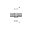
- FIG. 6 is a diagram showing manufacturing steps subsequent to FIG. 5. It is a figure which shows the manufacturing process following FIG. It is a figure which shows the manufacturing process of the rotor for embedded magnet synchronous motors of 2nd Embodiment.
- FIG. 9 is a diagram showing manufacturing steps subsequent to FIG. 8.
- FIG. 10 is a diagram showing a manufacturing process continued from FIG.
- FIG. 11 is a diagram showing a manufacturing process continued from FIG. 10.
- FIG. 12 is a diagram showing manufacturing steps subsequent to FIG. 11. It is a figure which shows the aggregate
- FIG. 1 the rotor 11 of this embodiment is shown with a top view.
- the rotor 11 includes a rotor core 12, a single shaft fastening hole 13 formed at the center of the rotor core 12, a rotor shaft 14 assembled in the shaft fastening hole 13, and a coupling that couples the rotor core 12 and the rotor shaft 14. And a structure.
- the rotor core 12 is formed by laminating thin steel plates having a thickness of 0.3 mm.
- a plurality of slots 15 are formed on the outer periphery of the rotor core 12.
- the plurality of slots 15 are arranged along the outer peripheral edge of the rotor core 12, and are arranged so that two adjacent slots 15 form a “C” shape or “reverse C shape”.
- a permanent magnet 31 (32) for field is incorporated and fixed.
- FIG. 2 is an enlarged plan view of the portion surrounded by the chain ellipse S1 of FIG.
- a center bridge portion 18 is formed between two adjacent slots 15 having an “inverted C shape” as a meat portion that divides both slots 15. Further, a boundary region portion 19 as a flesh portion is formed between each slot 15 and the outer peripheral edge of the rotor core 12.
- the permanent magnet 31 (32) incorporated in each slot 15 in the state in which the rotor 11 is assembled to the stator is brought close to the stator located around the rotor 11 in the boundary region. It is necessary to make the portion 19 as thin as possible.
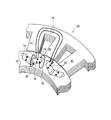
- FIG. 3 is a perspective view showing the structure of the nonmagnetic metal assembly 10. In FIG. 3, the fastening portions at both ends are omitted, and only the portion located in the rotor core 12 is illustrated. 4 to 7 show a manufacturing method in which the nonmagnetic metal assembly 10 is assembled and fixed to the rotor core 12.
- the substantially I-shaped assembly case 21 is formed with a pair of engaging portions 21 a that are swelled at both ends.
- the pair of engaging portions 21a are connected by an intermediate portion 21b.
- the material of the assembly case 21 is SUS304, which is a nonmagnetic metal, and the thickness is 0.3 mm.
- the area where the assembly case 21 and the rotor core 12 contact can be doubled by the engaging portion 21a.
- the specific resistance of SUS304 is the same as the specific resistance of the thin steel plate constituting the rotor core 12.
- a lower bolt member 23 having a male screw formed on the outer periphery is joined to the lower end of the assembly case 21 by welding.
- the lower bolt member 23 forms a bottom plate, and a thin wire 22 having a diameter of 0.3 mm is pushed into the assembly case 21 and is densely stored.
- the material of the thin wire 22 is SUS304 which is a nonmagnetic metal.
- An upper end 21 c for welding the upper bolt member 24 is formed at the upper end of the assembly case 21. Since the thin wire 22 does not exist inside the upper end portion 21c, the thickness of the upper end portion 21c may be thicker than the portion in which the thin wire 22 is stored.
- FIG. 4A a fine wire 22 that has been press-molded in advance into the space inside the assembly case 21 and whose outer shape is matched to the space of the assembly case 21 is pushed in and stored tightly.
- the state is shown in FIG.
- FIG. 4C the assembly case 21 in which the thin wires 22 are stored is inserted into the insertion holes 18 a formed in the center bridge portion 18 of the rotor core 12.
- the inserted state is shown in FIG.
- the fine line 22 is arranged so that the center line of the rotor and the center line of the fine line 22 are parallel to each other.
- the thin wire 22 is inserted in the center line direction with respect to the assembly case 21. Thereby, it arrange
- the upper end portion 21 c protrudes from the upper surface of the rotor core 12.
- the upper side bolt member 24 by which the external thread was formed in the outer peripheral surface is fitted by the outer periphery of the upper end part 21c.
- the upper bolt member 24 is welded to the upper end portion 21 c by the laser welding machine 25.
- the upper bolt member 24 constitutes an upper cover plate, and the thin wire 22 is hermetically held by the assembly case 21, the lower bolt member 23, and the upper bolt member 24.
- the upper nut member 26 is screwed to the upper bolt member 24.
- the lower nut member 27 is screwed to the lower bolt member 23.
- the upper nut member 26 and the lower nut member 27 are evenly screwed with the same force, and the thin wire 22 accommodated in the assembly case 21 is fixed to the rotor core 12.
- the non-magnetic metal assembly 10 is configured by the thin wire 22, the assembly case 21, the upper bolt member 24, the lower bolt member 23, the upper nut member 26, and the lower nut member 27.
- FIG. 15 shows a state where the rotor for a magnet-embedded synchronous motor according to the present invention is incorporated in the stator 40.
- the coil is omitted.
- An effective magnetic flux IA generated by a coil (not shown) flows through the teeth 41 to the permanent magnets 31 and 32 in the rotor core 12.
- the leakage magnetic flux IB shown in FIG. Since the leakage magnetic flux IB passing through the center bridge portion 18 is small, it is possible to provide a motor with high motor efficiency without reducing motor efficiency.
- the nonmagnetic metal is integrally formed as in the prior art, there is a problem that eddy current loss occurs due to leakage magnetic flux.
- the nonmagnetic metal aggregate 10 that is an aggregate of the thin wires 22 is used, the generation of eddy current loss is less than or equal to the eddy current loss generated in the rotor core 12 made of laminated steel sheets, Eddy current loss can be reduced. That is, the eddy current induced by the magnetic flux is generated on the metal surface. In the same metal solid, an eddy current corresponding to the magnetic flux strength is generated, but another metal solid is strongly pressed. However, almost no eddy current flows between them.
- the eddy current magnitude is proportional to the square of the thickness of the steel plates, and the magnitude of the eddy current generated in the laminated steel plates is approximately one sheet. It may be considered that it is determined by the thickness of the steel plate.
- the thickness of the thin wire 22 is 0.3 mm opposite to the direction in which the magnetic flux passes, the magnitude of the eddy current is proportional to the square of the thickness of the thin wire 22 and is therefore non-magnetic. The eddy current loss can be greatly reduced as compared with the case where the metals are integrated.
- the fine wire 22 which is a nonmagnetic metal is densely filled, and the upper bolt member 24, the lower bolt member 23, the upper nut member 26, and the lower nut member 27 at both ends are securely attached to the rotor core 12. Since the non-magnetic metal assembly 10 is securely fixed to the rotor core 12, the non-magnetic metal assembly 10 does not shift with respect to the rotor core 12, and the rotor rotates at high speed. Sufficient strength can be secured against the centrifugal force of the permanent magnet 31 (32).
- the nonmagnetic metal assembly 10 disposed in the center bridge portion 18 has been described.
- the basic configuration of the nonmagnetic metal assembly 9 disposed in the boundary region portion 19 is the same.
- the boundary region 19 is close to the outer peripheral edge of the rotor core 12, the upper bolt member 24, the lower bolt member 23, the upper nut member 26, and the lower nut member 27 do not protrude from the outer peripheral edge. Need to be placed. Further, both ends of the hole may be closed by welding the cover without using the bolt members 23 and 24 and the nut members 26 and 27, and the nonmagnetic metal aggregate 9 is attached to the hole of the rotor core 12. You may press fit.
- the two permanent magnets 31 (32) are embedded in the rotor core 12 with a gap therebetween.
- a rotor 11 for a synchronous motor with a built-in magnet which has nonmagnetic metal assemblies 10 and 9 in a rotor core 12 forming a slot 15 into which a permanent magnet 31 (32) is inserted.
- the magnitude of the eddy current induced when the magnetic flux passes through the nonmagnetic metal assembly 10 is limited by the thickness (0.3 mm) of the thin wire 22, it becomes extremely small, and the eddy current The current loss can be reduced and the nonmagnetic metal assembly 10 is used, so that sufficient strength can be secured against the centrifugal force of the permanent magnet 31 (32) when rotating at high speed. That.
- the upper bolt member 24 is pulled upward by the upper nut member 26 and the lower bolt member 23 is pulled downward by the lower nut member 27, the nonmagnetic metal assembly 10 is securely attached to the rotor core 12.
- the nonmagnetic metal assembly 10 is not displaced with respect to the rotor core 12, and the centrifugal force generated by the permanent magnet 31 (32) can be received integrally with the rotor core 12, thereby increasing the strength of the rotor core 12. be able to.
- the thickness (0.3 mm) of the thin wire 22 is set to be equal to or less than the thickness (0.3 mm) of the electromagnetic steel sheet forming the rotor core, the magnitude of the eddy current generated in the electromagnetic steel sheet Since a large eddy current is not generated, a new eddy current loss is hardly generated.
- the case is filled with an assembly of fine wires 22, and when installed in the insertion hole 18 a formed in the rotor core 12, the upper end portion 21 c protruding from both end portions of the rotor core 12 and the lower bolt member 23. In the production line, the assembly efficiency of the rotor is increased, because the thin wire 22 can be handled integrally by storing the thin wire 22 in the assembly case 21. Cost can be reduced.
- the assembly case 21 since the assembly case 21 has the engaging part 21a engaged with the rotor core 12, it is a nonmagnetic metal that may be generated by the centrifugal force of the permanent magnet 31 (32) when rotating at high speed. Deviation of the assembly 10 with respect to the rotor core 12 can be reliably prevented. That is, since the contact surface with the rotor core 12 can be made large as the engaging portion 21 a, the nonmagnetic metal assembly 10 does not shift with respect to the rotor core 12 even when a force is applied to the nonmagnetic metal assembly 10. .
- a rotor for a magnet-embedded synchronous motor according to a second embodiment of the present invention. Since the second embodiment is basically the same configuration and operation as the first embodiment, only the differences will be described in detail, and the description of the same parts will be omitted.
- 8 to 12 show a method for manufacturing the rotor for a magnet-embedded synchronous motor according to the second embodiment.
- an assembly of small spheres is used as the nonmagnetic assembly.
- the diameter of the small sphere is 0.3 mm
- the material is SUS304 which is a nonmagnetic metal.
- the assembly case 21 is the same as in the first embodiment.
- small balls 30 are filled into the assembly case 21.
- it inserts in the insertion hole 18a as it is.
- the inserted state is shown in FIG.
- the assembly case 21 filled with the small balls 30 is pressed in the vertical direction using the press die 28.
- the assembly case 21 and the small balls 30 spread laterally in the insertion hole 18a and fill the insertion hole 18a without any gaps.
- the press die 28 is raised.
- the following steps are the same as those in the first embodiment. 10 is the same as the process shown in FIG. 5, the process shown in FIG. 11 is the same as the process shown in FIG. 6, and the process shown in FIG. 12 is the same as the process shown in FIG. It is. Therefore, a detailed description is omitted.
- the diameter (0.3 mm) of the small sphere 30 corresponds to the direction in which the magnetic flux passes, regardless of which direction the small sphere 30 is arranged. Is limited by the diameter of the small sphere (0.3 mm), so that eddy current loss can be reduced.
- the small balls 30 having a diameter of 0.3 mm are used as the assembly filled in the assembly case 21. Unlike the thin wire 22, there is no directionality, so that it can be arranged freely. Further, since the small balls 30 filled in the assembly case 21 are pressed and strongly pressed against the inner wall surface of the insertion hole 18a of the rotor core 12, the centrifugal force of the permanent magnet 31 (32) when the rotor core 12 rotates at high speed. In contrast, sufficient strength can be secured. Naturally, the magnitude of the eddy current induced when the magnetic flux passes through the non-magnetic metal assembly 10 is limited by the diameter (0.3 mm) of the small sphere 30 and thus becomes extremely small. Loss can be reduced
- a rotor for a magnet-embedded synchronous motor according to a third embodiment of the present invention will be described. Since the third embodiment is basically the same configuration and operation as the first embodiment, only the differences will be described in detail, and the description of the same parts will be omitted.
- a thin plate of SUS304 which is a nonmagnetic metal having a thickness of 0.3 mm, is used as the aggregate.
- the assembly case 21 is omitted, and the arrangement direction of the thin plates 33 arranged in the assembly case 21 is shown.
- the thin plates 33 have the same arrangement direction as the arrangement of the laminated steel plates of the rotor core 12.
- the magnitude of the eddy current induced when the magnetic flux passes through the non-magnetic metal assembly 10 is limited by the thickness (0.3 mm) of the thin plate 33, and thus becomes extremely small. Current loss can be reduced.
- the thin plates 34 may be arranged as shown in FIG.
- the thin plates 34 are arranged in parallel to the center line connecting the engaging portions at both ends in a direction orthogonal to the laminated steel plates of the rotor core 12.
- the magnitude of the eddy current induced when the magnetic flux passes through the non-magnetic metal assembly 10 is limited by the thickness (0.3 mm) of the thin plate 33, and thus becomes extremely small. Current loss can be reduced.
- the handling of the assembly is performed as compared with the case where the thin wire 22 or the small sphere 30 is used. Has the advantage of easy.
- the rotor for a magnet-embedded synchronous motor is not limited to the above-described embodiment, and various applications are possible.
- the example in which the nonmagnetic metal assembly 10 is disposed in the center bridge portion 18 has been mainly described.
- the boundary region 19 is close to the outer peripheral edge of the rotor core 12, the upper bolt member 24, the lower bolt member 23, the upper nut member 26, and the lower nut member 27 do not protrude from the outer peripheral edge. Need to be placed.
- both ends of the hole may be closed by welding the cover without using the bolt members 23, 24 and the nut members 26, 27, and the nonmagnetic metal aggregate 9 may be attached to the hole of the rotor core 12.
- the thickness of the thin wire 22, the diameter of the small sphere 30, and the thickness of the thin plate 33 (34) are the same length as the thickness 0.3 mm of the laminated steel plate of the rotor core 12. As long as the thickness of the laminated steel sheet is shorter than 0.3 mm, it may be adopted as appropriate.
- SUS304 is used as the nonmagnetic metal, but another nonmagnetic metal such as SUS305 may be used.
- a magnetic material having a high electrical resistance such as NiCr may be used.
- This relates to a rotor for a magnet-embedded synchronous motor formed by embedding two permanent magnets in one magnetic pole with a gap therebetween and embedded in a rotor core.
Landscapes
- Engineering & Computer Science (AREA)
- Power Engineering (AREA)
- Permanent Field Magnets Of Synchronous Machinery (AREA)
- Iron Core Of Rotating Electric Machines (AREA)
Abstract
1つの磁極に2つの永久磁石が間隔を開けてロータコアに埋め込まれて形成された磁石埋め込み型同期モータ用ロータであって、永久磁石が挿入される磁石孔を形成するロータコア内(特には、センターブリッジ部)に、非磁性金属の集合体を有する。
Description
本発明は、1つの磁極に2つの永久磁石が間隔を開けてロータコアに埋め込まれて形成された磁石埋め込み型同期モータ用ロータに関するものである。
従来、ハイブリッド自動車用駆動用モータとして、エネルギ効率の高い磁石埋め込み型同期モータが使用されている。特に、1つの磁極に、2つの永久磁石が間隔を開けてロータコアに埋め込まれたものが、使用されている。それは、2つの永久磁石の補助磁極に起因するリアクタンストルクを利用でき、高いモータ効率を得られるためである。
図16に、従来の磁石埋め込み型同期モータ用ロータとステータ40との関係を示す。ステータ40では、コイルを省略して示している。図示しないコイルにより発生した有効磁束IAは、ティース41を通って、ロータコア12内の永久磁石31、32へと流れる。永久磁石31と永久磁石32とは、磁極の向きが逆向きに配置されている。
しかし、上記磁石埋め込み型同期モータ用ロータには、次のような問題がある。すなわち、永久磁石31と永久磁石32の間付近、いわゆるセンターブリッジ部18、または永久磁石31(32)と外周縁との間の境界領域部19を、漏れ磁束IBが通り抜ける問題があった。センターブリッジ部18や境界領域部19を通り抜ける漏れ磁束IBは、モータのトルクに寄与しないため、モータ効率を低下させる問題がある。
その問題を解決するために、センターブリッジ部18や境界領域部19に空孔を形成することが考えられるが、それでは、ロータの強度不足、特に高回転数で回転したときに、永久磁石31(32)で発生する遠心力をカバーする強度に強度不足の懸念がある。
図16に、従来の磁石埋め込み型同期モータ用ロータとステータ40との関係を示す。ステータ40では、コイルを省略して示している。図示しないコイルにより発生した有効磁束IAは、ティース41を通って、ロータコア12内の永久磁石31、32へと流れる。永久磁石31と永久磁石32とは、磁極の向きが逆向きに配置されている。
しかし、上記磁石埋め込み型同期モータ用ロータには、次のような問題がある。すなわち、永久磁石31と永久磁石32の間付近、いわゆるセンターブリッジ部18、または永久磁石31(32)と外周縁との間の境界領域部19を、漏れ磁束IBが通り抜ける問題があった。センターブリッジ部18や境界領域部19を通り抜ける漏れ磁束IBは、モータのトルクに寄与しないため、モータ効率を低下させる問題がある。
その問題を解決するために、センターブリッジ部18や境界領域部19に空孔を形成することが考えられるが、それでは、ロータの強度不足、特に高回転数で回転したときに、永久磁石31(32)で発生する遠心力をカバーする強度に強度不足の懸念がある。
この強度不足の問題を解決するために、特許文献1では、非磁性金属材料、または樹脂材料をセンターブリッジ部18に設けることが提案されている。
また、特許文献2では、センターブリッジ部18を非磁性体により形成すること、特に、渦電流の増大による損失を回避するために、樹脂等の絶縁体により形成することが提案されている。
また、特許文献2では、センターブリッジ部18を非磁性体により形成すること、特に、渦電流の増大による損失を回避するために、樹脂等の絶縁体により形成することが提案されている。
しかしながら、特許文献1,2に記載された発明には、次のような問題があった。
すなわち、非磁性金属を使用する場合には、ロータの強度は確保できるが、非磁性金属内を磁束が流れたときに、誘起電流による渦電流損失が発生し、モータ効率が低下する問題があった。
一方、樹脂等の絶縁体を使用する場合には、誘起電流が発生することなく渦電流損失を回避することはできるが、ロータコアの強度不足が問題であった。すなわち、ハイブリッド自動車で使用される磁石埋め込み型同期モータは、1万回転以上の高速回転される場合があるが、そのような高速回転では、永久磁石に発生する遠心力が大きく、ロータコアの一部を樹脂で構成すると、樹脂部分が強度的に耐えることができず、破損する恐れがある。そのため、ロータコアの一部に樹脂を使用することは、ハイブリッド自動車では、実現性がなかった。
すなわち、非磁性金属を使用する場合には、ロータの強度は確保できるが、非磁性金属内を磁束が流れたときに、誘起電流による渦電流損失が発生し、モータ効率が低下する問題があった。
一方、樹脂等の絶縁体を使用する場合には、誘起電流が発生することなく渦電流損失を回避することはできるが、ロータコアの強度不足が問題であった。すなわち、ハイブリッド自動車で使用される磁石埋め込み型同期モータは、1万回転以上の高速回転される場合があるが、そのような高速回転では、永久磁石に発生する遠心力が大きく、ロータコアの一部を樹脂で構成すると、樹脂部分が強度的に耐えることができず、破損する恐れがある。そのため、ロータコアの一部に樹脂を使用することは、ハイブリッド自動車では、実現性がなかった。
本発明は、上記問題点を解決することを目的とし、渦電流損失を回避すると共に、ロータの強度を維持可能な磁石埋め込み型同期モータ用ロータを提供することを目的とする。
本発明の一態様における磁石埋め込み型同期モータ用ロータは、次のような構成を有している。
(1)1つの磁極に2つの永久磁石が間隔を開けてロータコアに埋め込まれて形成された磁石埋め込み型同期モータ用ロータであって、永久磁石が挿入される磁石孔を形成するロータコア内に、非磁性金属の集合体を有することを特徴とする。
(2)(1)に記載する磁石埋め込み型同期モータ用ロータにおいて、前記2つの永久磁石の間の前記ロータコア内(センターブリッジ部)に、前記非磁性金属の集合体を有する。
(3)(1)または(2)に記載する磁石埋め込み型同期モータ用ロータにおいて、非磁性金属の集合体は、小球の集合体、細線の集合体、積層薄板のいずれか1つであることを特徴とする。ここで、細線を用いる場合には、ロータの中心線と細線の中心線が略平行になるように、細線を配列する。また、積層薄板を用いる場合には、ロータの半径方向と積層薄板の配置方向がほぼ平行となるように、積層薄板を配列する。すなわち、磁束の方向に垂直な面が、細分化されているように、細線や薄板を配列する。
(1)1つの磁極に2つの永久磁石が間隔を開けてロータコアに埋め込まれて形成された磁石埋め込み型同期モータ用ロータであって、永久磁石が挿入される磁石孔を形成するロータコア内に、非磁性金属の集合体を有することを特徴とする。
(2)(1)に記載する磁石埋め込み型同期モータ用ロータにおいて、前記2つの永久磁石の間の前記ロータコア内(センターブリッジ部)に、前記非磁性金属の集合体を有する。
(3)(1)または(2)に記載する磁石埋め込み型同期モータ用ロータにおいて、非磁性金属の集合体は、小球の集合体、細線の集合体、積層薄板のいずれか1つであることを特徴とする。ここで、細線を用いる場合には、ロータの中心線と細線の中心線が略平行になるように、細線を配列する。また、積層薄板を用いる場合には、ロータの半径方向と積層薄板の配置方向がほぼ平行となるように、積層薄板を配列する。すなわち、磁束の方向に垂直な面が、細分化されているように、細線や薄板を配列する。
(4)(3)に記載する磁石埋め込み型同期モータ用ロータにおいて、前記小球の直径、前記細線の太さ、前記薄板の厚さを、ロータコアを形成している電磁鋼板の厚さ以下とすることを特徴とする。
(5)(1)乃至(4)に記載する磁石埋め込み型同期モータ用ロータのいずれか1つにおいて、内部に前記集合体が充填されるケースであって、ロータコアに形成したケース孔に装着されたときに、前記ロータコアの両端部から突き出た締結部を備える集合体ケースを有することを特徴とする。
締結部の締結方法としては、例えば、締結部に外周面に雄ネジが形成されたボルト部材を溶接し、ナットで締結する方法、締結部にカシメ部を形成し、カシメ部をかしめることにより締結する方法が考えられる。
(6)(5)に記載する磁石埋め込み型同期モータ用ロータにおいて、前記集合体ケースが、前記ロータコアと係合する係合部を有することを特徴とする。
(5)(1)乃至(4)に記載する磁石埋め込み型同期モータ用ロータのいずれか1つにおいて、内部に前記集合体が充填されるケースであって、ロータコアに形成したケース孔に装着されたときに、前記ロータコアの両端部から突き出た締結部を備える集合体ケースを有することを特徴とする。
締結部の締結方法としては、例えば、締結部に外周面に雄ネジが形成されたボルト部材を溶接し、ナットで締結する方法、締結部にカシメ部を形成し、カシメ部をかしめることにより締結する方法が考えられる。
(6)(5)に記載する磁石埋め込み型同期モータ用ロータにおいて、前記集合体ケースが、前記ロータコアと係合する係合部を有することを特徴とする。
本発明の磁石埋め込み型同期モータ用ロータは、次のような作用、効果を奏する。
(1)、(3)1つの磁極に2つの永久磁石が間隔を開けてロータコアに埋め込まれて形成された磁石埋め込み型同期モータ用ロータであって、永久磁石が挿入される磁石孔を形成するロータコア内に、非磁性金属の集合体を有することを特徴とするので、非磁性金属の集合体内を磁束が通過するときに、誘起される渦電流の大きさは、細線の太さにより制限されるため、極めて小さいものとなり、渦電流損失を低減することができると共に、非磁性金属の集合体を用いているため、高速回転した場合の永久磁石の遠心力に対して、十分な強度を確保することができる。
磁束により誘起される渦電流は、金属表面に発生することを特徴とし、同じ金属固体内では、磁束強さに対応する渦電流を発生するが、別な金属固体が強く押圧されていても、その間では渦電流はほとんど流れることはない。すなわち、ロータコアを積層鋼板で構成した場合に、渦電流大きさは、鋼板の厚みの2乗に比例することが知られており、積層鋼板で発生する渦電流の大きさは、ほぼ1枚の鋼板の厚みで決定されると考えてよい。
(1)、(3)1つの磁極に2つの永久磁石が間隔を開けてロータコアに埋め込まれて形成された磁石埋め込み型同期モータ用ロータであって、永久磁石が挿入される磁石孔を形成するロータコア内に、非磁性金属の集合体を有することを特徴とするので、非磁性金属の集合体内を磁束が通過するときに、誘起される渦電流の大きさは、細線の太さにより制限されるため、極めて小さいものとなり、渦電流損失を低減することができると共に、非磁性金属の集合体を用いているため、高速回転した場合の永久磁石の遠心力に対して、十分な強度を確保することができる。
磁束により誘起される渦電流は、金属表面に発生することを特徴とし、同じ金属固体内では、磁束強さに対応する渦電流を発生するが、別な金属固体が強く押圧されていても、その間では渦電流はほとんど流れることはない。すなわち、ロータコアを積層鋼板で構成した場合に、渦電流大きさは、鋼板の厚みの2乗に比例することが知られており、積層鋼板で発生する渦電流の大きさは、ほぼ1枚の鋼板の厚みで決定されると考えてよい。
(2)、(3)1つの磁極に2つの永久磁石が間隔を開けてロータコアに埋め込まれて形成された磁石埋め込み型同期モータ用ロータであって、2つの永久磁石の間のロータコア内(センターブリッジ部)に、非磁性金属(小球の集合体、細線の集合体、積層薄板のいずれか1つ)の集合体を有するので、非磁性金属の集合体内を磁束が通過するときに、誘起される渦電流の大きさは、細線の太さにより制限されるため、極めて小さいものとなり、渦電流損失を低減することができると共に、非磁性金属の集合体を用いているため、高速回転した場合の永久磁石の遠心力に対して、十分な強度を確保することができる。
磁束により誘起される渦電流は、金属表面に発生することを特徴とし、同じ金属固体内では、磁束強さに対応する渦電流を発生するが、別な金属固体が強く押圧されていても、その間では渦電流はほとんど流れることはない。すなわち、ロータコアを積層鋼板で構成した場合に、渦電流大きさは、鋼板の厚みの2乗に比例することが知られており、積層鋼板で発生する渦電流の大きさは、ほぼ1枚の鋼板の厚みで決定されると考えてよい。これと同様に、細線の場合には、細線の太さにより渦電流損失の大きさが決定される。
磁束により誘起される渦電流は、金属表面に発生することを特徴とし、同じ金属固体内では、磁束強さに対応する渦電流を発生するが、別な金属固体が強く押圧されていても、その間では渦電流はほとんど流れることはない。すなわち、ロータコアを積層鋼板で構成した場合に、渦電流大きさは、鋼板の厚みの2乗に比例することが知られており、積層鋼板で発生する渦電流の大きさは、ほぼ1枚の鋼板の厚みで決定されると考えてよい。これと同様に、細線の場合には、細線の太さにより渦電流損失の大きさが決定される。
(4)(1)または(2)に記載する磁石埋め込み型同期モータ用ロータにおいて、前記小球の直径、前記細線の太さ、前記薄板の厚さを、ロータコアを形成している電磁鋼板の厚さ以下とすることを特徴とするので、電磁鋼板で発生する渦電流の大きさより大きな渦電流を発生することがないため、新たな渦電流損失をほとんど発生することがない。
(5)(1)乃至(4)に記載する磁石埋め込み型同期モータ用ロータのいずれか1つにおいて、内部に前記集合体が充填されるケースであって、ロータコアに形成したケース孔に装着されたときに、前記ロータコアの両端部から突き出た締結部を備える集合体ケースを有することを特徴とするので、小球、細線、積層薄板を集合体ケースに収納することにより、一体的に取り扱うことができるため、生産ラインにおいて、ロータの組み立て効率を高くして、コストを低減することができる。
(6)(5)に記載する磁石埋め込み型同期モータ用ロータにおいて、前記集合体ケースが、前記ロータコアと係合する係合部を有することを特徴とするので、高速回転した場合の永久磁石の遠心力により発生する恐れのある集合体ケースの、ロータコアに対するずれを防止することができる。すなわち、係合部としてロータコアとの接触面を大きく取ることができるため、集合体が充填された集合体ケースに力が加わっても、集合体ケースがずれることがない。
(5)(1)乃至(4)に記載する磁石埋め込み型同期モータ用ロータのいずれか1つにおいて、内部に前記集合体が充填されるケースであって、ロータコアに形成したケース孔に装着されたときに、前記ロータコアの両端部から突き出た締結部を備える集合体ケースを有することを特徴とするので、小球、細線、積層薄板を集合体ケースに収納することにより、一体的に取り扱うことができるため、生産ラインにおいて、ロータの組み立て効率を高くして、コストを低減することができる。
(6)(5)に記載する磁石埋め込み型同期モータ用ロータにおいて、前記集合体ケースが、前記ロータコアと係合する係合部を有することを特徴とするので、高速回転した場合の永久磁石の遠心力により発生する恐れのある集合体ケースの、ロータコアに対するずれを防止することができる。すなわち、係合部としてロータコアとの接触面を大きく取ることができるため、集合体が充填された集合体ケースに力が加わっても、集合体ケースがずれることがない。
本発明に係る磁石埋め込み型同期モータ用ロータの第1の実施形態について、図面を参照しながら詳細に説明する。
図1に、本実施形態のロータ11を平面図により示す。ロータ11は、ロータコア12と、ロータコア12の中心に形成された一つのシャフト締付孔13と、そのシャフト締付孔13に組み付けられたロータシャフト14と、ロータコア12とロータシャフト14を結合させる結合構造とを備える。
この実施形態で、ロータコア12は、厚さ0.3mmの薄板鋼板を積層することにより形成される。図1に示すように、ロータコア12の外周部には、複数のスロット15が形成される。複数のスロット15は、ロータコア12の外周縁に沿って配列され、隣り合う2つのスロット15が「ハの字状」又は「逆ハの字状」をなすように配置される。各スロット15には、それぞれ界磁用の永久磁石31(32)が組み込まれて固定される。
図1に、本実施形態のロータ11を平面図により示す。ロータ11は、ロータコア12と、ロータコア12の中心に形成された一つのシャフト締付孔13と、そのシャフト締付孔13に組み付けられたロータシャフト14と、ロータコア12とロータシャフト14を結合させる結合構造とを備える。
この実施形態で、ロータコア12は、厚さ0.3mmの薄板鋼板を積層することにより形成される。図1に示すように、ロータコア12の外周部には、複数のスロット15が形成される。複数のスロット15は、ロータコア12の外周縁に沿って配列され、隣り合う2つのスロット15が「ハの字状」又は「逆ハの字状」をなすように配置される。各スロット15には、それぞれ界磁用の永久磁石31(32)が組み込まれて固定される。
また、ロータコア12には、シャフト締付孔13と複数のスロット15との間にて、シャフト締付孔13の周囲に複数(この実施形態では「8個」)の孔17が形成される。これらの孔17は、平面視で略台形状をなし、ロータコア12を軸方向に貫通する。これらの孔17は、「逆ハの字状」をなす二つ一組のスロット15の間に一つずつ配置される。 図2に、ロータ11につき図1の鎖線楕円S1で囲んだ部分を拡大して平面図により示す。「逆ハの字状」をなす隣り合う二つのスロット15の間には、両スロット15を区画する肉部分としてのセンターブリッジ部18が形成される。また、各スロット15からロータコア12の外周縁までの間には、肉部分としての境界領域部19が形成される。モータを構成するために、このロータ11がステータに組み付けられた状態で、各スロット15に組み込まれた永久磁石31(32)を、ロータ11の周囲に位置するステータに近付けるためには、境界領域部19を極力薄くする必要がある。
図1に示すセンターブリッジ部18には、図2に示すように、非磁性金属集合体10が固定されている。また、図1に示す境界領域部19には、図2に示すように非磁性金属集合体9が固定されている。
非磁性金属集合体10と非磁性金属集合体9の構成は基本的に同じなので、本実施の形態では、センターブリッジ部18に固定された非磁性金属集合体10について詳細に説明する。
図3に、非磁性金属集合体10の構造を斜視図で示す。図3では、両端の締結部を省略して、ロータコア12内に位置する部分のみを図示している。図4から図7に、非磁性金属集合体10をロータコア12に組み込んで固定する製造方法を示す。
図3に示すように、略I字型の集合体ケース21は、両端部に膨らんだ部分である一対の係合部21aが形成されている。一対の係合部21aは、中間部21bにより接続している。集合体ケース21の材質は、非磁性金属であるSUS304であり、厚みは0.3mmである。係合部21aにより、集合体ケース21とロータコア12の接触する面積を倍増することができる。SUS304の比抵抗は、ロータコア12を構成している薄板鋼板の比抵抗と同じである。
非磁性金属集合体10と非磁性金属集合体9の構成は基本的に同じなので、本実施の形態では、センターブリッジ部18に固定された非磁性金属集合体10について詳細に説明する。
図3に、非磁性金属集合体10の構造を斜視図で示す。図3では、両端の締結部を省略して、ロータコア12内に位置する部分のみを図示している。図4から図7に、非磁性金属集合体10をロータコア12に組み込んで固定する製造方法を示す。
図3に示すように、略I字型の集合体ケース21は、両端部に膨らんだ部分である一対の係合部21aが形成されている。一対の係合部21aは、中間部21bにより接続している。集合体ケース21の材質は、非磁性金属であるSUS304であり、厚みは0.3mmである。係合部21aにより、集合体ケース21とロータコア12の接触する面積を倍増することができる。SUS304の比抵抗は、ロータコア12を構成している薄板鋼板の比抵抗と同じである。
図4(a)に示すように、集合体ケース21の下端には、外周に雄ネジが形成された下側ボルト部材23が溶接により接合されている。下側ボルト部材23は、底板を形成しており、集合体ケース21内には、直径0.3mmの細線22が、押し込まれて密に収納されている。細線22の材質は、非磁性金属であるSUS304である。集合体ケース21の上端部には、上側ボルト部材24を溶接するための上端部21cが形成されている。上端部21cの内側には細線22が存在しないため、上端部21cの厚みは、細線22が収納されている部分よりも肉厚にしても良い。
次に、非磁性金属集合体10をロータコア12に組み込んで固定する製造方法について説明する。
図4(a)に示すように、集合体ケース21内の空間に、予めプレス成形されて、外形が集合体ケース21の空間に合わせられている細線22を押し込んで密に収納する。その状態を図4(b)に示す。次に、図4(c)に示すように、細線22が収納された集合体ケース21をロータコア12のセンターブリッジ部18に形成された挿入孔18aに挿入する。挿入した状態を、図5(a)に示す。細線22は、ロータの中心線と細線22の中心線が平行になるように配置されている。すなわち、細線22は、集合体ケース21に対して、中心線方向に挿入されている。これにより、磁束の通過方向に対して、細線22が直交するように配置される。
この状態では、上端部21cは、ロータコア12の上面より突き出ている。次に、図5(b)に示すように、上端部21cの外周に、外周面に雄ネジが形成された上側ボルト部材24を嵌合させる。
次に、非磁性金属集合体10をロータコア12に組み込んで固定する製造方法について説明する。
図4(a)に示すように、集合体ケース21内の空間に、予めプレス成形されて、外形が集合体ケース21の空間に合わせられている細線22を押し込んで密に収納する。その状態を図4(b)に示す。次に、図4(c)に示すように、細線22が収納された集合体ケース21をロータコア12のセンターブリッジ部18に形成された挿入孔18aに挿入する。挿入した状態を、図5(a)に示す。細線22は、ロータの中心線と細線22の中心線が平行になるように配置されている。すなわち、細線22は、集合体ケース21に対して、中心線方向に挿入されている。これにより、磁束の通過方向に対して、細線22が直交するように配置される。
この状態では、上端部21cは、ロータコア12の上面より突き出ている。次に、図5(b)に示すように、上端部21cの外周に、外周面に雄ネジが形成された上側ボルト部材24を嵌合させる。
次に、図6に示すように、レーザ溶接機25により、上側ボルト部材24を上端部21cに溶接結合させる。上側ボルト部材24は上蓋板を構成し、細線22は、集合体ケース21、下側ボルト部材23、及び上側ボルト部材24により、密閉保持される。
次に、上側ボルト部材24に対して上側ナット部材26をネジ締結する。同時に、下側ボルト部材23に対して下側ナット部材27をネジ締結する。そして、上側ナット部材26と下側ナット部材27とを同じ力で均等にネジ込んでいき、ロータコア12に対して、集合体ケース21に収納された細線22を固定する。これにより、細線22が充填された集合体ケース21は、ロータコア12に対して確実に固定されるため、遠心力が作用しても、細線22が充填された集合体ケース21が、ロータコア12に対してずれることがない。
細線22、集合体ケース21、上側ボルト部材24、下側ボルト部材23、上側ナット部材26、及び下側ナット部材27により、非磁性金属集合体10が構成される。
次に、上側ボルト部材24に対して上側ナット部材26をネジ締結する。同時に、下側ボルト部材23に対して下側ナット部材27をネジ締結する。そして、上側ナット部材26と下側ナット部材27とを同じ力で均等にネジ込んでいき、ロータコア12に対して、集合体ケース21に収納された細線22を固定する。これにより、細線22が充填された集合体ケース21は、ロータコア12に対して確実に固定されるため、遠心力が作用しても、細線22が充填された集合体ケース21が、ロータコア12に対してずれることがない。
細線22、集合体ケース21、上側ボルト部材24、下側ボルト部材23、上側ナット部材26、及び下側ナット部材27により、非磁性金属集合体10が構成される。
次に、上記構成を有する磁石埋め込み型同期モータ用ロータの効果について説明する。図15に、本発明の磁石埋め込み型同期モータ用ロータを、ステータ40に組み込んだ状態を示す。ステータ40では、コイルを省略して示している。図示しないコイルにより発生した有効磁束IAは、ティース41を通って、ロータコア12内の永久磁石31、32へと流れる。
このとき、永久磁石31と永久磁石32の中間付近である、センターブリッジ部18には、非磁性金属集合体10が配置されているので、図16に示す漏れ磁束IBが通り抜けることが少ない。センターブリッジ部18を通り抜ける漏れ磁束IBが少ないため、モータ効率を低下させることがなく、モータ効率の高いモータを提供することができる。
このとき、永久磁石31と永久磁石32の中間付近である、センターブリッジ部18には、非磁性金属集合体10が配置されているので、図16に示す漏れ磁束IBが通り抜けることが少ない。センターブリッジ部18を通り抜ける漏れ磁束IBが少ないため、モータ効率を低下させることがなく、モータ効率の高いモータを提供することができる。
ここで、従来技術のように、非磁性金属を一体で構成した場合には、漏れ磁束により、渦電流損失が発生する問題があった。しかし、本実施の形態では、細線22の集合体である非磁性金属集合体10を用いているので、渦電流損失の発生は、積層鋼板からなるロータコア12に発生する渦電流損失以下であり、渦電流損失を低減できる。
すなわち、磁束により誘起される渦電流は、金属表面に発生することを特徴とし、同じ金属固体内では、磁束強さに対応する渦電流を発生するが、別な金属固体が強く押圧されていても、その間では渦電流はほとんど流れることはない。すなわち、ロータコア12を積層鋼板で構成した場合に、渦電流大きさは、鋼板の厚みの2乗に比例することが知られており、積層鋼板で発生する渦電流の大きさは、ほぼ1枚の鋼板の厚みで決定されると考えてよい。同様に、細線22は、磁束が通過する方向に対して、太さ0.3mmが対向しているため、渦電流の大きさは、細線22の太さの2乗に比例するため、非磁性金属が一体である場合と比較して、渦電流損失を大幅に低減することができる。
また、非磁性金属である細線22が密に充填されており、両端部の上側ボルト部材24、下側ボルト部材23、上側ナット部材26、及び下側ナット部材27により、ロータコア12に対して確実に固定されているので、非磁性金属集合体10はロータコア12に対して確実に固定されているため、非磁性金属集合体10がロータコア12に対してずれることがなく、ロータが高速回転した場合の永久磁石31(32)の遠心力に対して、十分な強度を確保することができる。
すなわち、磁束により誘起される渦電流は、金属表面に発生することを特徴とし、同じ金属固体内では、磁束強さに対応する渦電流を発生するが、別な金属固体が強く押圧されていても、その間では渦電流はほとんど流れることはない。すなわち、ロータコア12を積層鋼板で構成した場合に、渦電流大きさは、鋼板の厚みの2乗に比例することが知られており、積層鋼板で発生する渦電流の大きさは、ほぼ1枚の鋼板の厚みで決定されると考えてよい。同様に、細線22は、磁束が通過する方向に対して、太さ0.3mmが対向しているため、渦電流の大きさは、細線22の太さの2乗に比例するため、非磁性金属が一体である場合と比較して、渦電流損失を大幅に低減することができる。
また、非磁性金属である細線22が密に充填されており、両端部の上側ボルト部材24、下側ボルト部材23、上側ナット部材26、及び下側ナット部材27により、ロータコア12に対して確実に固定されているので、非磁性金属集合体10はロータコア12に対して確実に固定されているため、非磁性金属集合体10がロータコア12に対してずれることがなく、ロータが高速回転した場合の永久磁石31(32)の遠心力に対して、十分な強度を確保することができる。
上記実施の形態では、センターブリッジ部18に配置する非磁性金属集合体10について説明したが、境界領域部19に配置する非磁性金属集合体9についても、基本的構成は同じである。ただし、境界領域部19では、ロータコア12の外周縁に近いため、上側ボルト部材24、下側ボルト部材23、上側ナット部材26、及び下側ナット部材27が外周縁から外にはみ出さないように配置する必要がある。また、ボルト部材23、24や、ナット部材26、27を用いずに、孔の両端を、カバーを溶接することにより塞いでも良いし、ロータコア12の孔に対して、非磁性金属集合体9を圧入しても良い。
以上詳細に説明したように、本発明の第1実施の形態の磁石埋め込み型同期モータ用ロータによれば、1つの磁極に2つの永久磁石31(32)が間隔を開けてロータコア12に埋め込まれて形成された磁石埋め込み型同期モータ用ロータ11であって、永久磁石31(32)が挿入されるスロット15を形成するロータコア12内に、非磁性金属集合体10、9を有することを特徴とするので、非磁性金属集合体10内を磁束が通過するときに、誘起される渦電流の大きさは、細線22の太さ(0.3mm)により制限されるため、極めて小さいものとなり、渦電流損失を低減することができると共に、非磁性金属集合体10を用いているため、高速回転した場合の永久磁石31(32)の遠心力に対して、十分な強度を確保することができる。
特に、上側ナット部材26により上側ボルト部材24を上向きに引き上げると共に、下側ナット部材27により下側ボルト部材23を下向きに引き下げているので、非磁性金属集合体10をロータコア12に対して、確実に固定できるため、非磁性金属集合体10がロータコア12に対してずれることがなく、永久磁石31(32)による遠心力をロータコア12と一体となって受けることができ、ロータコア12の強度を強めることができる。
特に、上側ナット部材26により上側ボルト部材24を上向きに引き上げると共に、下側ナット部材27により下側ボルト部材23を下向きに引き下げているので、非磁性金属集合体10をロータコア12に対して、確実に固定できるため、非磁性金属集合体10がロータコア12に対してずれることがなく、永久磁石31(32)による遠心力をロータコア12と一体となって受けることができ、ロータコア12の強度を強めることができる。
また、細線22の太さ(0.3mm)を、ロータコアを形成している電磁鋼板の厚さ(0.3mm)以下とすることを特徴とするので、電磁鋼板で発生する渦電流の大きさより大きな渦電流を発生することがないため、新たな渦電流損失をほとんど発生することがない。
また、内部に細線22の集合体が充填されるケースであって、ロータコア12に形成した挿入孔18aに装着されたときに、ロータコア12の両端部から突き出た上端部21c、下側ボルト部材23を備える集合体ケース21を有することを特徴とするので、細線22を集合体ケース21に収納することにより、一体的に取り扱うことができるため、生産ラインにおいて、ロータの組み立て効率を高くして、コストを低減することができる。
また、集合体ケース21が、ロータコア12と係合する係合部21aを有することを特徴とするので、高速回転した場合の永久磁石31(32)の遠心力により発生する恐れのある非磁性金属集合体10のロータコア12に対するずれを確実に防止することができる。すなわち、係合部21aとしてロータコア12との接触面を大きく取ることができるため、非磁性金属集合体10に力が加わっても、非磁性金属集合体10がロータコア12に対してずれることがない。
また、内部に細線22の集合体が充填されるケースであって、ロータコア12に形成した挿入孔18aに装着されたときに、ロータコア12の両端部から突き出た上端部21c、下側ボルト部材23を備える集合体ケース21を有することを特徴とするので、細線22を集合体ケース21に収納することにより、一体的に取り扱うことができるため、生産ラインにおいて、ロータの組み立て効率を高くして、コストを低減することができる。
また、集合体ケース21が、ロータコア12と係合する係合部21aを有することを特徴とするので、高速回転した場合の永久磁石31(32)の遠心力により発生する恐れのある非磁性金属集合体10のロータコア12に対するずれを確実に防止することができる。すなわち、係合部21aとしてロータコア12との接触面を大きく取ることができるため、非磁性金属集合体10に力が加わっても、非磁性金属集合体10がロータコア12に対してずれることがない。
次に、本発明の第2の実施の形態の磁石埋め込み型同期モータ用ロータについて説明する。第2の実施の形態は、基本的には、第1の実施の形態と同じ構成・作用なので、相違する点のみ詳細に説明し、同じ部分については説明を割愛する。
図8から図12に第2の実施の形態の磁石埋め込み型同期モータ用ロータの製造方法を示す。第2の実施の形態では、非磁性集合体として、小球の集合体を用いている。小球の直径は、0.3mmであり、材質は非磁性金属であるSUS304である。
小球30を用いる場合には、細線22のように事前に成形するよりも、ロータコア12の挿入孔18aに挿入した後で、成形する方が、作業性が良いので、そのようにしている。
図8(a)に示すように、集合体ケース21は、第1実施の形態と同じである。図8(b)に示すように、集合体ケース21の中に、小球30を充填する。そして、そのまま挿入孔18aに挿入する。挿入した状態を図9(a)に示す。図に示すように、集合体ケース21の外周と挿入孔18aとの間には、少しの隙間がある。これは、集合体ケース21を挿入孔18aに挿入しやすくするための隙間である。
図8から図12に第2の実施の形態の磁石埋め込み型同期モータ用ロータの製造方法を示す。第2の実施の形態では、非磁性集合体として、小球の集合体を用いている。小球の直径は、0.3mmであり、材質は非磁性金属であるSUS304である。
小球30を用いる場合には、細線22のように事前に成形するよりも、ロータコア12の挿入孔18aに挿入した後で、成形する方が、作業性が良いので、そのようにしている。
図8(a)に示すように、集合体ケース21は、第1実施の形態と同じである。図8(b)に示すように、集合体ケース21の中に、小球30を充填する。そして、そのまま挿入孔18aに挿入する。挿入した状態を図9(a)に示す。図に示すように、集合体ケース21の外周と挿入孔18aとの間には、少しの隙間がある。これは、集合体ケース21を挿入孔18aに挿入しやすくするための隙間である。
次に、ロータコア12と下側ボルト部材23を下側から支持した状態で、プレス金型28を用いて、小球30の充填された集合体ケース21を上下方向にプレスする。これにより、図9(b)に示すように、集合体ケース21と小球30は、挿入孔18aの中で横方向に広がって、挿入孔18a内を隙間なく充填する。その後、図9(c)に示すように、プレス金型28が上昇する。
以下の工程は、第1実施の形態と同じである。すなわち、図10に示す工程は、図5に示す工程と同じであり、図11に示す工程は、図6に示す工程と同じであり、図12に示す工程は、図7に示す工程と同じである。したがって、詳細な説明を割愛する。
小球30を用いる場合には、どちらの方向に小球30を配置したとしても、磁束の通る方向に対して、小球30の直径(0.3mm)が対応するので、発生する渦電流損失は、小球の直径(0.3mm)により制限されるため、渦電流損失を低減することができる。
以下の工程は、第1実施の形態と同じである。すなわち、図10に示す工程は、図5に示す工程と同じであり、図11に示す工程は、図6に示す工程と同じであり、図12に示す工程は、図7に示す工程と同じである。したがって、詳細な説明を割愛する。
小球30を用いる場合には、どちらの方向に小球30を配置したとしても、磁束の通る方向に対して、小球30の直径(0.3mm)が対応するので、発生する渦電流損失は、小球の直径(0.3mm)により制限されるため、渦電流損失を低減することができる。
以上詳細に説明したように、第2実施の形態の磁石埋め込み型同期モータ用ロータによれば、集合体ケース21内に充填する集合体として、直径0.3mmの小球30を用いているので、細線22と違って方向性がないため、自由に配置することができる。
また、集合体ケース21に充填した小球30をプレスしてロータコア12の挿入孔18aの内壁面に強く押圧しているので、ロータコア12が高速回転した場合の永久磁石31(32)の遠心力に対して、十分な強度を確保することができる。
当然、非磁性金属集合体10内を磁束が通過するときに、誘起される渦電流の大きさは、小球30の直径(0.3mm)により制限されるため、極めて小さいものとなり、渦電流損失を低減することができる
また、集合体ケース21に充填した小球30をプレスしてロータコア12の挿入孔18aの内壁面に強く押圧しているので、ロータコア12が高速回転した場合の永久磁石31(32)の遠心力に対して、十分な強度を確保することができる。
当然、非磁性金属集合体10内を磁束が通過するときに、誘起される渦電流の大きさは、小球30の直径(0.3mm)により制限されるため、極めて小さいものとなり、渦電流損失を低減することができる
次に、本発明の第3の実施の形態の磁石埋め込み型同期モータ用ロータについて説明する。第3の実施の形態は、基本的には、第1の実施の形態と同じ構成・作用なので、相違する点のみ詳細に説明し、同じ部分については説明を割愛する。
図13に示すように、第3の実施例では、集合体として、厚さ0.3mmの非磁性金属であるSUS304の薄板を用いている。図では、集合体ケース21を省略して、集合体ケース21内に配列された薄板33の配列方向を記載している。
薄板33は、図13に示すように、ロータコア12の積層鋼板の配列と同じ配列方向である。これにより、非磁性金属集合体10内を磁束が通過するときに、誘起される渦電流の大きさは、薄板33の厚さ(0.3mm)により制限されるため、極めて小さいものとなり、渦電流損失を低減することができる。
図13に示すように、第3の実施例では、集合体として、厚さ0.3mmの非磁性金属であるSUS304の薄板を用いている。図では、集合体ケース21を省略して、集合体ケース21内に配列された薄板33の配列方向を記載している。
薄板33は、図13に示すように、ロータコア12の積層鋼板の配列と同じ配列方向である。これにより、非磁性金属集合体10内を磁束が通過するときに、誘起される渦電流の大きさは、薄板33の厚さ(0.3mm)により制限されるため、極めて小さいものとなり、渦電流損失を低減することができる。
集合体として、薄板を用いるときの配列方向としては、図14に示すように、薄板34を配列しても良い。薄板34は、ロータコア12の積層鋼板に対して直交する方向で、両端の係合部を結ぶ中心線に対して平行に配列されている。
これにより、非磁性金属集合体10内を磁束が通過するときに、誘起される渦電流の大きさは、薄板33の厚さ(0.3mm)により制限されるため、極めて小さいものとなり、渦電流損失を低減することができる。
以上説明したように、図13または図14に示す第3の実施の形態によれば、薄板33(34)を用いているので、細線22や小球30を用いる場合よりも、集合体の取り扱いが容易となる利点を有する。
これにより、非磁性金属集合体10内を磁束が通過するときに、誘起される渦電流の大きさは、薄板33の厚さ(0.3mm)により制限されるため、極めて小さいものとなり、渦電流損失を低減することができる。
以上説明したように、図13または図14に示す第3の実施の形態によれば、薄板33(34)を用いているので、細線22や小球30を用いる場合よりも、集合体の取り扱いが容易となる利点を有する。
本発明の磁石埋め込み型同期モータ用ロータは、上記実施の形態に限定されることなく、色々な応用が可能である。
例えば、本実施の形態では、センターブリッジ部18に、非磁性金属集合体10を配置する例について主に説明したが、境界領域部19に非磁性金属集合体9を配設するときも、ほぼ同様である。
ただし、境界領域部19では、ロータコア12の外周縁に近いため、上側ボルト部材24、下側ボルト部材23、上側ナット部材26、及び下側ナット部材27が外周縁から外にはみ出さないように配置する必要がある。また、ボルト部材23、24や、ナット部材26、27を用いずに、孔の両端を、カバーを溶接することにより塞いでも良いし、ロータコア12の孔に対して、非磁性金属集合体9を圧入しても良い。
また、本実施の形態では、細線22の太さ、小球30の直径、薄板33(34)の厚さとして、ロータコア12の積層鋼板の厚さ0.3mmと同じ長さを用いているが、積層鋼板の厚さ0.3mmより短い寸法であれば、適宜採用すれば良い。
また、本実施の形態では、非磁性金属として、SUS304を用いているが、他の非磁性金属、例えばSUS305等を用いても良い。
更に、細線や小球の径が0.3mmを超えてしまう場合、NiCrのような電気抵抗の高い磁性材料を用いても良い。
例えば、本実施の形態では、センターブリッジ部18に、非磁性金属集合体10を配置する例について主に説明したが、境界領域部19に非磁性金属集合体9を配設するときも、ほぼ同様である。
ただし、境界領域部19では、ロータコア12の外周縁に近いため、上側ボルト部材24、下側ボルト部材23、上側ナット部材26、及び下側ナット部材27が外周縁から外にはみ出さないように配置する必要がある。また、ボルト部材23、24や、ナット部材26、27を用いずに、孔の両端を、カバーを溶接することにより塞いでも良いし、ロータコア12の孔に対して、非磁性金属集合体9を圧入しても良い。
また、本実施の形態では、細線22の太さ、小球30の直径、薄板33(34)の厚さとして、ロータコア12の積層鋼板の厚さ0.3mmと同じ長さを用いているが、積層鋼板の厚さ0.3mmより短い寸法であれば、適宜採用すれば良い。
また、本実施の形態では、非磁性金属として、SUS304を用いているが、他の非磁性金属、例えばSUS305等を用いても良い。
更に、細線や小球の径が0.3mmを超えてしまう場合、NiCrのような電気抵抗の高い磁性材料を用いても良い。
1つの磁極に2つの永久磁石が間隔を開けてロータコアに埋め込まれて形成された磁石埋め込み型同期モータ用ロータに関するものである。
9、10 非磁性金属集合体
11 ロータ
12 ロータコア
18 センターブリッジ部
19 境界領域部
21 集合体ケース
21a 係合部
22 細線
23 下側ボルト部材
24 上側ボルト部材
26 上側ナット部材
27 下側ナット部材
30 小球
31、32 永久磁石
33、34 薄板
11 ロータ
12 ロータコア
18 センターブリッジ部
19 境界領域部
21 集合体ケース
21a 係合部
22 細線
23 下側ボルト部材
24 上側ボルト部材
26 上側ナット部材
27 下側ナット部材
30 小球
31、32 永久磁石
33、34 薄板
Claims (6)
- 1つの磁極に2つの永久磁石が間隔を開けてロータコアに埋め込まれて形成された磁石埋め込み型同期モータ用ロータにおいて、
前記永久磁石が挿入される磁石孔を形成する前記ロータコア内に、非磁性金属の集合体を有することを特徴とする磁石埋め込み型同期モータ用ロータ。 - 請求項1に記載する磁石埋め込み型同期モータ用ロータにおいて、
前記2つの永久磁石の間の前記ロータコア内に、前記非磁性金属の集合体を有することを特徴とする磁石埋め込み型同期モータ用ロータ。 - 請求項1または請求項2に記載する磁石埋め込み型同期モータ用ロータにおいて、
非磁性金属の集合体は、小球の集合体、細線の集合体、積層薄板のいずれか1つであることを特徴とする磁石埋め込み型同期モータ用ロータ。 - 請求項3に記載する磁石埋め込み型同期モータ用ロータにおいて、
前記小球の直径、前記細線の太さ、前記薄板の厚さを、ロータコアを形成している電磁鋼板の厚さ以下とすることを特徴とする磁石埋め込み型同期モータ用ロータ。 - 請求項1乃至請求項4に記載する磁石埋め込み型同期モータ用ロータのいずれか1つにおいて、
内部に前記集合体が充填されるケースであって、ロータコアに形成したケース孔に装着されたときに、前記ロータコアの両端部から突き出た締結部を備える集合体ケースを有することを特徴とする磁石埋め込み型同期モータ用ロータ。 - 請求項5に記載する磁石埋め込み型同期モータ用ロータにおいて、
前記集合体ケースが、前記ロータコアと係合する係合部を有することを特徴とする磁石埋め込み型同期モータ用ロータ。
Priority Applications (1)
| Application Number | Priority Date | Filing Date | Title |
|---|---|---|---|
| PCT/JP2010/056929 WO2011132250A1 (ja) | 2010-04-19 | 2010-04-19 | 磁石埋め込み型同期モータ用ロータ |
Applications Claiming Priority (1)
| Application Number | Priority Date | Filing Date | Title |
|---|---|---|---|
| PCT/JP2010/056929 WO2011132250A1 (ja) | 2010-04-19 | 2010-04-19 | 磁石埋め込み型同期モータ用ロータ |
Publications (1)
| Publication Number | Publication Date |
|---|---|
| WO2011132250A1 true WO2011132250A1 (ja) | 2011-10-27 |
Family
ID=44833812
Family Applications (1)
| Application Number | Title | Priority Date | Filing Date |
|---|---|---|---|
| PCT/JP2010/056929 Ceased WO2011132250A1 (ja) | 2010-04-19 | 2010-04-19 | 磁石埋め込み型同期モータ用ロータ |
Country Status (1)
| Country | Link |
|---|---|
| WO (1) | WO2011132250A1 (ja) |
Cited By (4)
| Publication number | Priority date | Publication date | Assignee | Title |
|---|---|---|---|---|
| JP2014068472A (ja) * | 2012-09-26 | 2014-04-17 | Hitachi Automotive Systems Ltd | 回転電機、磁極ピース製造方法 |
| TWI580158B (zh) * | 2016-01-08 | 2017-04-21 | Taiwan Electric Motor Co Ltd | 同步馬達之轉子的結構 |
| EP3629447A1 (en) * | 2018-09-28 | 2020-04-01 | General Electric Company | Electric machine assembly with reduced rotor post leakage |
| US11362553B2 (en) | 2019-01-18 | 2022-06-14 | Ford Global Technologies, Llc | Motor rotor |
Citations (4)
| Publication number | Priority date | Publication date | Assignee | Title |
|---|---|---|---|---|
| JPH09163648A (ja) * | 1995-12-11 | 1997-06-20 | Yaskawa Electric Corp | 内磁形同期モータ |
| JP2008278696A (ja) * | 2007-05-02 | 2008-11-13 | Sumitomo Electric Ind Ltd | モータおよびロータ |
| JP2009201269A (ja) * | 2008-02-22 | 2009-09-03 | Fuji Electric Systems Co Ltd | 埋込磁石モータおよびその製造方法 |
| WO2009154007A1 (ja) * | 2008-06-20 | 2009-12-23 | 株式会社 東芝 | 永久磁石式回転電機 |
-
2010
- 2010-04-19 WO PCT/JP2010/056929 patent/WO2011132250A1/ja not_active Ceased
Patent Citations (4)
| Publication number | Priority date | Publication date | Assignee | Title |
|---|---|---|---|---|
| JPH09163648A (ja) * | 1995-12-11 | 1997-06-20 | Yaskawa Electric Corp | 内磁形同期モータ |
| JP2008278696A (ja) * | 2007-05-02 | 2008-11-13 | Sumitomo Electric Ind Ltd | モータおよびロータ |
| JP2009201269A (ja) * | 2008-02-22 | 2009-09-03 | Fuji Electric Systems Co Ltd | 埋込磁石モータおよびその製造方法 |
| WO2009154007A1 (ja) * | 2008-06-20 | 2009-12-23 | 株式会社 東芝 | 永久磁石式回転電機 |
Cited By (7)
| Publication number | Priority date | Publication date | Assignee | Title |
|---|---|---|---|---|
| JP2014068472A (ja) * | 2012-09-26 | 2014-04-17 | Hitachi Automotive Systems Ltd | 回転電機、磁極ピース製造方法 |
| TWI580158B (zh) * | 2016-01-08 | 2017-04-21 | Taiwan Electric Motor Co Ltd | 同步馬達之轉子的結構 |
| EP3629447A1 (en) * | 2018-09-28 | 2020-04-01 | General Electric Company | Electric machine assembly with reduced rotor post leakage |
| CN110971098A (zh) * | 2018-09-28 | 2020-04-07 | 通用电气公司 | 减少转子柱泄漏的电机组件 |
| US11095198B2 (en) | 2018-09-28 | 2021-08-17 | General Electric Company | Electric machine assembly with reduced rotor post leakage |
| US11606012B2 (en) | 2018-09-28 | 2023-03-14 | General Electric Company | Electric machine assembly with reduced rotor post leakage |
| US11362553B2 (en) | 2019-01-18 | 2022-06-14 | Ford Global Technologies, Llc | Motor rotor |
Similar Documents
| Publication | Publication Date | Title |
|---|---|---|
| CN104054237B (zh) | 转子铁芯、马达以及马达的制造方法 | |
| CN104704714B (zh) | 永磁体埋入型电动机 | |
| JP5370433B2 (ja) | 永久磁石埋設型電動モータ | |
| JP5502571B2 (ja) | 永久磁石式回転電機 | |
| US8937417B2 (en) | Rotating electric machine and wind power generation system | |
| EP2293421A2 (en) | Permanent magnet electrical machine and its manufacturing method | |
| CN109314413B (zh) | 永磁铁式同步机及永磁铁式同步机的固定件的制造方法 | |
| CN110086274A (zh) | 永久磁铁埋入型电动机及其制造方法 | |
| WO2014034344A1 (ja) | 回転電機 | |
| CN101931274A (zh) | 模块化式电机定子结构及其应用 | |
| JP2013059262A (ja) | 固定子鉄心及び固定子及び電動機及び圧縮機 | |
| JP2010119192A (ja) | 永久磁石形モータ | |
| JP5531841B2 (ja) | 電動機 | |
| JP5672149B2 (ja) | 回転電機用ロータ、および、これを用いた回転電機 | |
| JP5493792B2 (ja) | Ipmモータ用ロータとipmモータ | |
| WO2011132250A1 (ja) | 磁石埋め込み型同期モータ用ロータ | |
| CN109845070B (zh) | 转子以及旋转电机 | |
| JP6112970B2 (ja) | 永久磁石式回転電機 | |
| GB2506932A (en) | Laminated rotor assembly | |
| JP2011125163A (ja) | 電動機ロータ | |
| JP5176466B2 (ja) | 埋込磁石同期モータのロータおよび埋込磁石同期モータ | |
| JP5653298B2 (ja) | 永久磁石埋込型モータの回転子 | |
| JP5793948B2 (ja) | 同期電動機 | |
| TWI584558B (zh) | Rotary motor stator core and stator, and rotary motor | |
| JP5261080B2 (ja) | リニアモータ |
Legal Events
| Date | Code | Title | Description |
|---|---|---|---|
| 121 | Ep: the epo has been informed by wipo that ep was designated in this application |
Ref document number: 10850195 Country of ref document: EP Kind code of ref document: A1 |
|
| NENP | Non-entry into the national phase |
Ref country code: DE |
|
| 122 | Ep: pct application non-entry in european phase |
Ref document number: 10850195 Country of ref document: EP Kind code of ref document: A1 |
|
| NENP | Non-entry into the national phase |
Ref country code: JP |