WO2011129298A1 - ガスタービンエンジンおよびそのタービン静翼 - Google Patents
ガスタービンエンジンおよびそのタービン静翼 Download PDFInfo
- Publication number
- WO2011129298A1 WO2011129298A1 PCT/JP2011/058997 JP2011058997W WO2011129298A1 WO 2011129298 A1 WO2011129298 A1 WO 2011129298A1 JP 2011058997 W JP2011058997 W JP 2011058997W WO 2011129298 A1 WO2011129298 A1 WO 2011129298A1
- Authority
- WO
- WIPO (PCT)
- Prior art keywords
- passage
- turbine
- gas turbine
- stationary blade
- blade
- Prior art date
Links
Images


Classifications
-
- F—MECHANICAL ENGINEERING; LIGHTING; HEATING; WEAPONS; BLASTING
- F01—MACHINES OR ENGINES IN GENERAL; ENGINE PLANTS IN GENERAL; STEAM ENGINES
- F01D—NON-POSITIVE DISPLACEMENT MACHINES OR ENGINES, e.g. STEAM TURBINES
- F01D9/00—Stators
- F01D9/06—Fluid supply conduits to nozzles or the like
- F01D9/065—Fluid supply or removal conduits traversing the working fluid flow, e.g. for lubrication-, cooling-, or sealing fluids
-
- F—MECHANICAL ENGINEERING; LIGHTING; HEATING; WEAPONS; BLASTING
- F01—MACHINES OR ENGINES IN GENERAL; ENGINE PLANTS IN GENERAL; STEAM ENGINES
- F01D—NON-POSITIVE DISPLACEMENT MACHINES OR ENGINES, e.g. STEAM TURBINES
- F01D9/00—Stators
- F01D9/02—Nozzles; Nozzle boxes; Stator blades; Guide conduits, e.g. individual nozzles
-
- F—MECHANICAL ENGINEERING; LIGHTING; HEATING; WEAPONS; BLASTING
- F05—INDEXING SCHEMES RELATING TO ENGINES OR PUMPS IN VARIOUS SUBCLASSES OF CLASSES F01-F04
- F05D—INDEXING SCHEME FOR ASPECTS RELATING TO NON-POSITIVE-DISPLACEMENT MACHINES OR ENGINES, GAS-TURBINES OR JET-PROPULSION PLANTS
- F05D2250/00—Geometry
- F05D2250/10—Two-dimensional
- F05D2250/18—Two-dimensional patterned
- F05D2250/185—Two-dimensional patterned serpentine-like
-
- F—MECHANICAL ENGINEERING; LIGHTING; HEATING; WEAPONS; BLASTING
- F05—INDEXING SCHEMES RELATING TO ENGINES OR PUMPS IN VARIOUS SUBCLASSES OF CLASSES F01-F04
- F05D—INDEXING SCHEME FOR ASPECTS RELATING TO NON-POSITIVE-DISPLACEMENT MACHINES OR ENGINES, GAS-TURBINES OR JET-PROPULSION PLANTS
- F05D2260/00—Function
- F05D2260/20—Heat transfer, e.g. cooling
- F05D2260/201—Heat transfer, e.g. cooling by impingement of a fluid
Definitions
- the present invention relates to a gas turbine engine and its turbine stationary blade, particularly an air-cooled turbine stationary blade.
- a turbine stationary blade of a gas turbine engine has a structure in which the turbine stationary blade is cooled by cooling air in order to improve the heat resistance of the blade body facing a passage through which high-temperature combustion gas generated by a combustor flows.
- air extracted from the compressor is introduced into a cooling passage formed inside the blade body.
- the efficiency of the gas turbine engine is reduced. Therefore, it is necessary to cool effectively with as little air as possible.
- the turbine stationary blade is generally cast, it is relatively difficult to form a small cooling passage inlet for introducing a small amount of cooling air into the stationary blade body.
- the introduction hole having a small opening area for introducing a small amount of air into the passage inlet 53 of the cooling passage 52 formed inside the blade body 51 of the turbine stationary blade 50.
- the structure which covers the adjustment plate 54 in which 58 is formed from the outside can be considered. In this structure, only a required amount of cooling air A can be introduced into the cooling passage 52 through the introduction hole 58 and the passage inlet 53. However, as a result of the numerical analysis, the cooling air A immediately after being introduced from the passage inlet 53 is drifted. As a result, in the front and rear regions S1 and S2 in the vicinity of the passage inlet 53, a stagnation or low-speed flow of the cooling air A is formed. The Since the front-side (upstream side of the combustion gas G) region S1 is formed in the vicinity of the blade body front edge that should be cooled most because the combustion gas G directly hits it, effective cooling of the blade body 51 is achieved. Not done.
- An object of the present invention is to provide a turbine stationary blade having a cooling structure capable of effectively cooling a blade body with a small required air flow rate, and a gas turbine engine having the turbine stationary blade.
- a turbine stationary blade of a gas turbine has a blade body disposed facing a combustion gas passage.
- the blade main body has a cooling passage located on the upstream side of the gas turbine engine and extending radially with respect to the central axis of the gas turbine engine.
- the blade body has a passage inlet connected to the radially outer end of the cooling passage.
- the wing body has an adjustment member fixed to the wing body so as to cover the cooling air.
- the adjusting member is disposed apart from each other along the camber line CL of the stationary blade and is opened to the passage inlet, and two introduction holes are formed to guide the cooling air radially inward toward the passage inlet. ing.
- the cooling air is introduced into the cooling passage through the passage inlet from each of the two introduction holes arranged apart from each other along the camber line. Therefore, the introduced cooling air does not concentrate on the central portion of the cooling passage as in the case of introducing the cooling air from a single introduction hole. As a result, the drift of cooling air does not occur in the cooling passage. Further, the cooling air flows through the cooling passage with a uniform flow rate. Therefore, the turbine stationary blade, particularly the front edge portion can be effectively cooled. In addition, by setting the opening area of the two introduction holes so that the total flow rate of the cooling air passing through them becomes the required flow rate, the amount of cooling air is suppressed while obtaining a high cooling effect. Efficiency reduction can be prevented.
- the passage entrance has an elongated shape extending along the camber line.
- the passage entrance has a length L along the camber line.
- One of the two introduction holes located upstream is centered from the upstream end of the passage entrance to the rear of the 1/4 to 1/3 L along the camber line, and the center of the two introduction holes.
- the center of the other introduction hole located on the downstream side is located 2/3 to 3 / 4L behind the upstream end of the passage inlet.
- the two introduction holes are holes having the same inner diameter and a circular cross section.
- the two introduction holes can be formed by repeating the same process using one kind of drill twice, it is easy to process the adjusting member.
- the wing body has a flange on the radially outer side.
- a passage entrance is formed in the flange, and an adjustment member is fixed to the radially outer side surface of the flange.
- the adjustment member can be firmly fixed to the outer surface of the flange by fixing means such as welding.
- the cooling air passes through the passage inlet in a state of being dispersed from the two introduction holes provided apart along the camber line. Introduced in.
- the introduced cooling air is not concentrated in the central portion of the cooling passage.
- the occurrence of uneven flow of the cooling air in the cooling passage is suppressed and a uniform flow velocity is obtained.
- the edge can be cooled effectively. Further, by appropriately setting the opening areas of the two introduction holes, it is possible to suppress the amount of cooling air and prevent a reduction in the efficiency of the gas turbine while obtaining a high cooling effect.
- FIG. 1 It is a fragmentary longitudinal cross-sectional view of the gas turbine which concerns on one Embodiment of this invention. It is a disassembled perspective view of the stationary blade shown in FIG. It is a partial expansion perspective view of the stationary blade shown in FIG. FIG. 2 is a partially enlarged longitudinal sectional view of the stationary blade shown in FIG. 1. It is a fragmentary longitudinal cross-sectional view of the stationary blade shown in FIG.
- the gas turbine engine includes a compressor that compresses air, a combustor that supplies and burns fuel to compressed air from the compressor, and a turbine that is driven by high-temperature, high-pressure combustion gas from the combustor.
- the turbine T alternately turns the turbine stationary blades 1 and the turbine rotor blades 21 and 22 in an axial direction P parallel to the central axis (corresponding to the rotation axis of the rotor) of the gas turbine engine. It is arranged and configured. In general, one moving blade is arranged behind one stationary blade.
- an outer flange 3 and an inner flange 4 are integrally formed at the outer end and the inner end of the blade body 2 in the radial direction R of the turbine.
- the wing body 2 is cast using a mold.
- the outer flange 3 is integrally formed with outer mounting pieces 8 and 9 on the front side and the rear side in the axial direction P, respectively.
- the inner diameter side flange 4 is integrally formed with a locking projection 10 and an inner mounting piece 11 on the front side and the rear side in the axial direction P, respectively.
- the turbine vane 1 having such a configuration has the attachment pieces 8 and 9 of the outer flange 3 fitted into the fitting recesses 13 and 14 of the turbine casing 12 from the circumferential direction of the turbine.
- the main body 2 is supported by the turbine casing 12 so as to face the combustion gas passage 18 through which high-temperature combustion gas flows.
- the locking projection 10 of the inner flange 4 and the inner mounting piece 11 are engaged with or fitted into the connecting ring 41 on the radially inner side.
- the turbine casing 12 is formed with an air supply chamber 43 into which a required amount of compressed air A extracted from the compressor is supplied via the extraction passage 42 and the air inlet 23.
- a cooling passage 24 is formed by two partition walls 31 and 32 extending in the radial direction and formed integrally with the blade body 2.
- the cooling passage has three passage portions extending substantially parallel to the front wall 2, and the first passage portion adjacent to the front wall 2 a and the second passage portion on the rear side thereof are in the radial direction thereof. It is connected at the inner end, and the second passage portion and the third passage portion on the rear side thereof are connected at their radially outer end portions.
- a passage inlet 28 for introducing the cooling air A into the cooling passage 24 is formed in an outer flange portion on the radially inner side of the air inlet 23 of the outer flange 3.
- the passage inlet 28 opens the most upstream portion of the cooling passage 24 to the air supply chamber 43 in the vicinity of the front blade wall 2 a of the blade body 2.
- a cooling air amount adjusting plate 29 is provided in the air supply chamber 43. As shown in the figure, the adjustment plate 29 is fixed on the outer surface 3 a of the outer flange 3 so as to cover the passage inlet 28.
- the adjustment plate 29 is formed with two introduction holes 30, 30 for introducing the cooling air A toward the cooling passage 24 through the passage inlet 28.
- the cooling air A that has flowed to the most downstream side of the cooling passage 24 is pin-pin cooling passage 38 through the outlet hole 34 that is a gap between the plurality of guide walls 33, 33 arranged at intervals in the radial direction R. Then, after cooling the blade body 2 through a large number of pin fins 39 integrally formed with the blade body 2, the blade body 2 is discharged from the opening 40 of the rear wall 2 b of the blade body 2 to the combustion gas passage 18. Note that the pin fin 39 may be omitted.
- the passage inlet 28 is formed in the outer diameter side flange 3 in the vicinity of the front wall 2 a of the blade body 2, and when viewed from the outside in the radial direction R, the blade thickness of the blade body 2. It elongates along the camber line CL passing through the center.
- An adjustment member 29 having two introduction holes 30a and 30b is fixed to the outer surface 3a of the outer flange 3 by welding so as to cover the passage inlet 28.
- the two introduction holes 30a and 30b of the adjustment member 29 are through holes having a circular cross section with the same inner diameter, for example.
- the sizes and shapes of the introduction holes 30a and 30b are adjusted so that the flow rate of the cooling air A introduced into the cooling passage 24 through the introduction holes 30a and 30b becomes a required amount.
- the adjustment member 29 has two introduction holes 3030a and 30b that communicate with the passage inlet 28, and the centers of the introduction holes 30a and 30b are substantially located on the camber line CL. It is fixed to the outer diameter side flange 3.
- the passage inlet 28 has a length L (see FIG. 2) along the camber line CL.
- the center of the introduction hole 30a on the front side is located at a position spaced rearward from the front end of the passage inlet 28 by a distance L1 of 1 ⁇ 4 to 1L along the camber line CL.
- the center of the rear side (right side in the figure) of the introduction hole 30b is located at a position spaced rearward from the front end of the passage inlet 28 by a distance L2 of 2/3 to 3 / 4L along the camber line CL.
- the radially outer surface 50 a ( 5) is inclined radially outward toward the rear.
- the introduction hole 58 is formed in the plate thickness direction TD of the adjustment plate 54, the air blown into the cooling passage 52 from the introduction hole 58 goes in a direction away from the front wall.
- the two introduction holes 30a and 30b shown in FIG. 4 are formed such that the center axis of the introduction hole 30 is directed in the radial direction R in a state where the adjustment member 29 is fixed. Further, as described above, the two introduction holes 30a and 30b are spaced apart from each other on the camber line CL. Therefore, the cooling air supplied to the cooling passage 24 from the introduction holes 30 a and 30 b is dispersed throughout the cooling passage 24 without forming a drift.
- the cooling air A supplied from the compressor through the extraction passage 42 is supplied from the air supply chamber 43 of the turbine casing 12 to 2 of the adjusting member 29.
- the blade body 2 After being introduced into the cooling passage 24 through the two introduction holes 30 a and 30 b, the blade body 2 is cooled while flowing in the cooling passage 24.
- the cooling air A is dispersed from the two introduction holes 30 and 30 and introduced into the passage inlet 28 and further into the cooling passage 24. Therefore, the introduced cooling air A does not concentrate in the central portion of the cooling passage as in the case of introducing the cooling air A from a single introduction hole, and flows into the cooling passage 24 almost uniformly. As a result, there is no occurrence of uneven flow and there is almost no low flow velocity region in the flow of the cooling air A, so that the blade body 2 of the turbine stationary blade 1 can be effectively cooled.
- the center of the front introduction hole 30a is located 1 ⁇ 4 to 3L along the camber line CL from the front end of the passage inlet 28, and the center of the rear introduction hole 30b is 2/3 from the front end. Since it is located behind ⁇ 3 / 4L, the cooling air A can be introduced into the cooling passage 24 almost uniformly through the entire passage inlet 28. Further, since the front introduction hole 30a is located at the front side, the flow rate of the cooling air A flowing in the vicinity of the blade wall of the blade body leading edge 2a is sufficiently large, and as a result, the blade exposed to the high-temperature combustion gas G. The main body front edge 2a is effectively cooled.
- the central axes of the two introduction holes 30a and 30b are directed in the radial direction R, an even flow distribution of the cooling air A is obtained in the cooling passage 24, and the blade wall of the blade body leading edge 2a is obtained.
- the flow of the cooling air A along is reliably formed.
- the opening area of the two introduction holes 30a and 30b is determined so that the total flow rate of the cooling air A passing through them becomes a required flow rate, it is possible to obtain a high cooling effect while increasing the extraction amount. A reduction in efficiency of the gas turbine can be suppressed.
- the two introduction holes 30a and 30b of the adjustment member 29 have the same inner diameter, the same process is performed twice using one type of drill (that is, without exchanging the two drills).
- the adjustment member 29 can be easily formed by repeating the process. Further, since the passage inlet 28 is formed in the outer flange 3 and the adjustment member 29 is fixed to the outer surface 3a of the outer flange 3, the adjustment member 29 is fixed to the outer diameter side flange by simple fixing means such as welding. 3 can be firmly fixed.
- the present invention is not limited to the contents shown in the above embodiment, and various additions, modifications, or deletions are possible within the scope not departing from the gist of the present invention. It is included within the scope of the present invention.
Landscapes
- Engineering & Computer Science (AREA)
- Mechanical Engineering (AREA)
- General Engineering & Computer Science (AREA)
- Physics & Mathematics (AREA)
- Fluid Mechanics (AREA)
- Turbine Rotor Nozzle Sealing (AREA)
Abstract
ガスタービンエンジンは、少ない所要の空気流量で効果的に冷却できる冷却構造を備えたタービン静翼1を有する。タービン静翼は、燃焼ガス通路18に臨んで配置される翼本体2を有する。翼本体は、内部に、ガスタービンエンジンの上流側に位置しかつガスタービンエンジンの中心軸に対して径方向に伸びる冷却通路24を有する。翼本体は、冷却通路の径方向外側端部に接続する通路入口28を有する。翼本体は、冷却空気を覆うように翼本体に固定された調整部材29を有する。調整部材は、静翼のキャンバーラインCLに沿って互いに離間して配置されるとともに通路入口に開放されており、冷却空気を通路入口に向けて径方向内側に案内する2つの導入孔30a,30bが形成されている。
Description
本発明は、ガスタービンエンジンおよびそのタービン静翼、特に空冷式のタービン静翼、に関する。
一般に、ガスタービンエンジンのタービン静翼は、燃焼器で生成された高温の燃焼ガスが流れる通路に臨む翼本体の耐熱性向上を図るために、冷却用空気により該タービン静翼を冷却する構造を採用しており、そこでは、翼本体内部に形成された冷却通路に、圧縮機から抽出した空気を導入するようにしている。この冷却構造では、抽出された冷却空気量が多くなると、ガスタービンエンジンの効率低下を招くことになるので、できるだけ少ない空気量で効果的に冷却する必要がある。ところが、タービン静翼は、一般には鋳造されるものであることから、少量の冷却空気を静翼本体に導入するための小さな冷却通路入口を静翼に形成することは比較的難しい。そこで、従来、静翼の空気通路内に挿入されるインサート部材に、多数の調量孔が形成された流量調整プレートを装着することで、少ない所要の空気量で効果的に冷却できるようにした冷却構造が知られている(特許文献1参照)。しかしながら、この冷却構造は、インサート部材を用いることから、構造が複雑で、高価になる。
これに代わり、図5に示すように、タービン静翼50の翼本体51の内部に形成された冷却通路52の通路入口53に、少量の空気量を導入するための小さな開口面積を有する導入孔58が形成された調整プレート54を外側から被せる構造が考えられる。この構造では、所要量だけの冷却空気Aを導入孔58および通路入口53を介して冷却通路52内に導入できる。しかし、数値解析の結果、通路入口53から導入された直後の冷却空気Aに偏流が生じる結果、通路入口53の近傍の前後領域S1,S2に、冷却空気Aの滞留又は低速の流れが形成される。そして、前側(燃焼ガスGの上流側)の領域S1が、燃焼ガスGが直接当たるために最も冷却すべき翼本体前縁部の近傍に形成されるので、翼本体51の効果的な冷却がなされない。
本発明は、少ない所要の空気流量で効果的に翼本体を冷却できる冷却構造を備えたタービン静翼、およびそのタービン静翼を備えたガスタービンエンジンを提供することを目的とする。
上記目的を達成するために、本発明に係るガスタービンのタービン静翼は、燃焼ガス通路に臨んで配置される翼本体を有する。翼本体は、内部に、ガスタービンエンジンの上流側に位置しかつガスタービンエンジンの中心軸に対して径方向に伸びる冷却通路を有する。翼本体は、冷却通路の径方向外側端部に接続する通路入口を有する。翼本体は、冷却空気を覆うように翼本体に固定された調整部材を有する。調整部材は、静翼のキャンバーラインCLに沿って互いに離間して配置されるとともに通路入口に開放されており、冷却空気を通路入口に向けて径方向内側に案内する2つの導入孔が形成されている。
このタービン静翼によれば、冷却空気は、キャンバーライン沿って離間して配置された2つの導入孔のそれぞれから通路入口を介して冷却通路内に導入され。そのため、導入された冷却空気が、単一の導入孔から冷却空気を導入する場合のように、冷却通路の中央部分に集中することがない。その結果、冷却通路に冷却空気の偏流が発生することはない。また、均一な流速をもって冷却空気が冷却通路を流れる。したがって、タービン静翼、特に前縁部を効果的に冷却できる。また、2つの導入孔は、これらを通る冷却空気の合計流量が所要の流量となるようにその開口面積を設定することにより、高い冷却効果を得ながら、冷却空気量を抑制してガスタービンの効率低下を防止できる。
本発明の他の形態では、通路入口はキャンバーラインに沿って延びる細長い形状である。また、通路入口は、キャンバーラインに沿って長さLを有する。そして、2つの導入孔のうち上流側に位置する一方の導入孔はその中心が通路入口の上流端からキャンバーラインに沿って1/4~1/3L後方に位置し、2つの導入孔のうち下流側に位置する他方の導入孔はその中心が通路入口の上流端から2/3~3/4L後方に位置している。このように、2つの導入孔を配置することにより、冷却空気を通路入口の全体にわたりほぼ均一速度で通過させて冷却通路内に導入することができる。特に、一方の導入孔が、通路入口上流端から1/4~1/3L後方に位置しているので、タービン静翼の最も冷却が必要な前縁付近の流量が増し、この前縁付近が効果的に冷却される。
本発明の他の形態では、2つの導入孔は同一内径を有する横断面が円形の孔である。この場合、2つの導入孔は、一種類のドリルを用いた同一の工程を2回繰り返すことによって形成できるので、調整部材の加工が簡単である。
本発明の他の形態では、翼本体は径方向外側にフランジを備えている。また、フランジに通路入口が形成されており、フランジの径方向外側面に調整部材が固定されている。この場合、調整部材を溶接などの固定手段でフランジの外側面に強固に固定できる。
本発明のタービン静翼及びそれを備えたガスタービンエンジンによれば、冷却空気は、キャンバーラインに沿って離間して設けられた2つの導入孔から分散された状態で通路入口を通って冷却通路内に導入される。これにより、導入された冷却空気が冷却通路の中央部分に集中することがなくなる結果、冷却通路における冷却空気の偏流の発生が抑制されるとともに均一な流速が得られるので、タービン静翼の特に前縁部を効果的に冷却できる。また、2つの導入孔の開口面積を適宜設定することにより、高い冷却効果を得ながら、冷却空気量を抑制してガスタービンの効率低下を防止できる。
以下、本発明の好ましい実施形態について図面を参照しながら詳細に説明する。ガスタービンエンジンは、空気を圧縮する圧縮機、圧縮機からの圧縮空気に燃料を供給して燃焼させる燃焼器、および燃焼器からの高温、高圧の燃焼ガスにより駆動されるタービンを備えている。図1に示すように、タービンTは、ガスタービンエンジンの中心軸(ロータの回転軸に相当する。)に平行な軸方向Pに、タービン静翼1とタービン動翼21,22とを交互に配置して構成されている。一般には、一つの静翼の後側に一つの動翼が配置される。
図2に示すように、タービン静翼1は、タービンの径方向Rに関して翼本体2の外側端と内側端に外側フランジ3と内側フランジ4が一体的に形成されている。一般に、翼本体2は、鋳型を使って鋳造される。外側フランジ3には、軸方向Pの前側と後側にそれぞれ外側取付片8,9が一体に形成されている。また、内径側フランジ4には、軸方向Pの前側と後側にそれぞれ係止突起10と内側取付片11が一体に形成されている。
このような構成を有するタービン静翼1は、図1に示すように、外側フランジ3の取付片8,9がタービンケーシング12の嵌合凹所13,14にタービンの周方向から嵌め込まれ、翼本体2を高温の燃焼ガスが流れる燃焼ガス通路18内に臨ませて、タービンケーシング12に支持される。また、内側フランジ4の係止突起10と内側取付片11は、径方向内側の連結リング41に係合又は嵌合される。
図1に戻り、タービンケーシング12には、圧縮機から抽気された所要量の圧縮空気Aが抽気通路42および空気流入口23を介して供給される空気供給室43が形成されている。翼本体2の内部には、この翼本体2に一体形成された、径方向に延びる2つの仕切壁31,32によって冷却通路24が形成されている。実施形態では、冷却通路は、前壁2と略平行に伸びる3つの通路部分を有し、前壁2aに隣接する第1の通路部分とその後側にある第2の通路部分がそれらの径方向内側端部で連結されており、第2の通路部分とその後側にある第3の通路部分がそれらの径方向外側端部で連結されている。また、外側フランジ3の空気流入口23の径方向内側にある外側フランジ部分には、冷却空気Aを冷却通路24内に導入する通路入口28が形成されている。通路入口28は、翼本体2の前翼壁2aの近傍で、冷却通路24の最上流部を空気供給室43に開口している。空気供給室43には冷却空気量調整板29が設けてある。図示するように、調整板29は、外側フランジ3の外面3a上に通路入口28を覆うように、固定されている。調整板29は、通路入口28を介して冷却通路24に向けて冷却空気Aを導入するための2つの導入孔30,30が形成されている。
したがって、冷却通路24の最下流側まで流れた冷却空気Aは、径方向Rに間隔をあけて配置された複数のガイド壁33,33間の隙間である導出孔34を介してピンフィン冷却通路38に入り、そこで翼本体2に一体形成された多数のピンフィン39を介して翼本体2を冷却したのち、翼本体2の後壁2bの開口40から燃焼ガス通路18へ排出される。なお、ピンフィン39は省略される場合もある。
図2に示すように、通路入口28は、翼本体2の前壁2a近傍で、外径側フランジ3に形成されており、径方向Rの外方から見たとき、翼本体2の翼厚中心を通るキャンバーラインCLに沿って細長く伸びている。また、2つの導入孔30a,30bを有する調整部材29が、通路入口28を覆うように外側フランジ3の外面3aに溶接で固定されている。調整部材29の2つの導入孔30a,30bは例えば同一内径の円形横断面を有する貫通孔である。導入孔30a,30bの大きさと形状は、導入孔30a,30bを通じて冷却通路24に導入される冷却空気Aの流量が所要量となるように調整される。
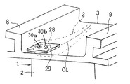
図3に示すように、調整部材29は、2つの導入孔3030a,30bが通路入口28に対向して連通し、かつ、導入孔30a,30bの中心をほぼキャンバーラインCL上に位置させて、外径側フランジ3に固定されている。図4を参照してさらに詳細に説明すると、通路入口28は、キャンバーラインCLに沿って、L(図2参照)の長さを有する。この場合、前側(図の左側)の導入孔30aの中心は、通路入口28の前端からキャンバーラインCLに沿って1/4~1/3Lの距離L1だけ後方に離間した位置にある。また、後側(図の右側)の導入孔30bの中心は、通路入口28の前端からキャンバーラインCLに沿って2/3~3/4Lの距離L2だけ後方に離間した位置にある。
また、図1,4,5に示すように、燃焼ガス通路59において、下流側(後方)に向かって径方向外側に広がる箇所では、これに合わせて、タービン静翼50の径方向外面50a(図5参照)が後方へ向かって径方向外側に傾斜している。この場合、調整プレート54の板厚方向TDに導入孔58が形成されていれば、その導入孔58から冷却通路52に吹き込まれる空気は、前壁から離れる方向に向かう。
これに対し、図4に示す2つの導入孔30a,30bは、調整部材29が固定された状態で、それら導入孔30の中心軸が径方向Rに向けられるように、形成されている。また、上述のように、2つの導入孔30a,30bは、キャンバーラインCL上に離間して配置されている。したがって、導入孔30a,30bから冷却通路24に供給された冷却空気は、冷却通路24内に偏流を形成することなく、その全体に分散する。
そのため、タービン静翼1によれば、図1、4に示すように、圧縮機から抽気通路42を通って供給された冷却空気Aは、タービンケーシング12の空気供給室43から調整部材29の2つの導入孔30a,30bを通って冷却通路24内に導入されたのち、冷却通路24内を流動しながら翼本体2を冷却する。このとき、冷却空気Aは、2つの導入孔30,30から分散して通路入口28、さらに冷却通路24内に導入される。したがって、導入された冷却空気Aは、単一の導入孔から冷却空気Aを導入する場合のように冷却通路の中央部分に集中することがなく、冷却通路24内にほぼ均一に流れ込む。その結果、偏流の発生が無く、冷却空気Aの流れに流速の低い領域が殆ど存在しなくなることから、タービン静翼1の翼本体2を効果的に冷却することができる。
特に、前側の導入孔30aはその中心が通路入口28の前端からキャンバーラインCLに沿って1/4~1/3L後方に位置し、後側の導入孔30bはその中心が前端から2/3~3/4L後方に位置しているので、冷却空気Aを通路入口28の全体にわたりほぼ均等に通過させて冷却通路24内に導入できる。また、前側の導入孔30aが前寄りに位置しているので、翼本体前縁2aの翼壁付近を流れる冷却空気Aの流量が十分大きくなり、その結果、高温の燃焼ガスGにさらされる翼本体前縁2aが効果的に冷却される。
さらに、2つの導入孔30a,30bの中心軸が径方向Rに向けられているので、一層、冷却通路24内に冷却空気Aの均等な流量分布が得られ、翼本体前縁2aの翼壁に沿った冷却空気Aの流れが確実に形成される。また、2つの導入孔30a,30bは、これらを通る冷却空気Aの合計流量が所要の流量となるように開口面積に決められているので、高い冷却効果を得ながらも、抽気量の増大によるガスタービンの効率低下を抑制することができる。
また、実施の形態では、調整部材29の2つの導入孔30a,30bは同一内径を有するので、一種類のドリルを用いて(すなわち、2つのドリルを交換することなく)同一の工程を2回繰り返すことによって形成でき、調整部材29の加工が容易である。さらに、外側フランジ3に通路入口28を形成し、外側フランジ3の外面3aに調整部材29を固定する構成を採用しているので、溶接などの簡易な固定手段で調整部材29を外径側フランジ3に強固に固定できる。
なお、本発明は、以上の実施形態で示した内容に限定されるものではなく、本発明の要旨を逸脱しない範囲内で、種々の追加、変更または削除が可能であり、そのようなものも本発明の範囲内に含まれる。
1 タービン静翼
2 翼本体
2a 前縁
3 外径側フランジ
12 タービンケーシング
18 燃焼ガス通路
24 冷却通路
28 通路入口
29 調整部材
30a,30b 導入孔
A 冷却空気
CL キャンバーライン
G 燃焼ガス
R 径方向
T タービン
2 翼本体
2a 前縁
3 外径側フランジ
12 タービンケーシング
18 燃焼ガス通路
24 冷却通路
28 通路入口
29 調整部材
30a,30b 導入孔
A 冷却空気
CL キャンバーライン
G 燃焼ガス
R 径方向
T タービン
Claims (5)
- ガスタービンエンジンのタービンケーシングに支持されるタービン静翼であって、
前記静翼は、燃焼ガス通路に臨んで配置される翼本体を有し、
前記翼本体は、内部に、前記ガスタービンエンジンの上流側に位置しかつ前記ガスタービンエンジンの中心軸に対して径方向に伸びる冷却通路を有し、
前記翼本体は、前記冷却通路の径方向外側端部に接続する通路入口を有し、
前記翼本体は、前記冷却空気を覆うように前記翼本体に固定された調整部材を有し、
前記調整部材は、前記静翼のキャンバーラインに沿って互いに離間して配置されるとともに前記通路入口に開放されており、前記冷却空気を前記通路入口に向けて径方向に案内する2つの導入孔が形成されている、ガスタービンのタービン静翼。 - 前記通路入口は前記キャンバーラインに沿って延びる細長い形状であり、
前記通路入口は、前記キャンバーラインに沿って長さLを有し、
前記2つの導入孔のうち前記上流側に位置する一方の導入孔は、その中心が前記通路入口の上流端からキャンバーラインに沿って1/4~1/3L後方に位置し、
前記2つの導入孔のうち下流側に位置する他方の導入孔は、その中心が前記通路入口の上流端から2/3~3/4L後方に位置している、請求項1のガスタービンのタービン静翼。 - 前記2つの導入孔は同一内径を有する横断面が円形の孔である、請求項1又は2のガスタービンのタービン静翼。
- 前記翼本体は径方向外側にフランジを備え、
前記フランジに前記通路入口が形成されており、
前記フランジの径方向外側面に前記調整部材が固定されている、請求項1~3のいずれかのカスタービンのタービン静翼。 - 圧縮機、燃焼器、およびタービンを有するガスタービンエンジンであって、
前記タービンが、請求項1~4のいずれかのタービン静翼を備えていることを特徴とする、ガスタービンエンジン。
Priority Applications (2)
| Application Number | Priority Date | Filing Date | Title |
|---|---|---|---|
| EP11768819.2A EP2559857B1 (en) | 2010-04-15 | 2011-04-11 | Gas turbine and turbine stationary blade for same |
| US13/641,063 US9234432B2 (en) | 2010-04-15 | 2011-04-11 | Gas turbine and turbine stationary blade for same |
Applications Claiming Priority (2)
| Application Number | Priority Date | Filing Date | Title |
|---|---|---|---|
| JP2010-093666 | 2010-04-15 | ||
| JP2010093666A JP4841678B2 (ja) | 2010-04-15 | 2010-04-15 | ガスタービンのタービン静翼 |
Publications (1)
| Publication Number | Publication Date |
|---|---|
| WO2011129298A1 true WO2011129298A1 (ja) | 2011-10-20 |
Family
ID=44798671
Family Applications (1)
| Application Number | Title | Priority Date | Filing Date |
|---|---|---|---|
| PCT/JP2011/058997 WO2011129298A1 (ja) | 2010-04-15 | 2011-04-11 | ガスタービンエンジンおよびそのタービン静翼 |
Country Status (4)
| Country | Link |
|---|---|
| US (1) | US9234432B2 (ja) |
| EP (1) | EP2559857B1 (ja) |
| JP (1) | JP4841678B2 (ja) |
| WO (1) | WO2011129298A1 (ja) |
Families Citing this family (12)
| Publication number | Priority date | Publication date | Assignee | Title |
|---|---|---|---|---|
| EP2941784B1 (en) * | 2012-12-10 | 2017-02-15 | Sieva, Podjetje Za Razvoj In Trzenje V Avtomobilski Industrij, D.O.O. | Advanced heat exchanger with integrated coolant fluid flow deflector |
| US9464538B2 (en) * | 2013-07-08 | 2016-10-11 | General Electric Company | Shroud block segment for a gas turbine |
| US9518478B2 (en) * | 2013-10-28 | 2016-12-13 | General Electric Company | Microchannel exhaust for cooling and/or purging gas turbine segment gaps |
| JP6245739B2 (ja) * | 2013-11-19 | 2017-12-13 | 三菱日立パワーシステムズ株式会社 | ガスタービンの冷却構造 |
| JP6230383B2 (ja) * | 2013-11-21 | 2017-11-15 | 三菱日立パワーシステムズ株式会社 | 蒸気タービンの静翼と蒸気タービン |
| US8864438B1 (en) * | 2013-12-05 | 2014-10-21 | Siemens Energy, Inc. | Flow control insert in cooling passage for turbine vane |
| US10436113B2 (en) | 2014-09-19 | 2019-10-08 | United Technologies Corporation | Plate for metering flow |
| CN107849925B (zh) * | 2015-07-06 | 2020-03-17 | 西门子股份公司 | 具有冷却流量调节特征的涡轮机定子叶片和/或涡轮机转子叶片以及适应叶片的对应方法 |
| GB201612646D0 (en) * | 2016-07-21 | 2016-09-07 | Rolls Royce Plc | An air cooled component for a gas turbine engine |
| KR102152415B1 (ko) * | 2018-10-16 | 2020-09-04 | 두산중공업 주식회사 | 터빈 베인 및 터빈 블레이드 및 이를 포함하는 가스 터빈 |
| KR102180395B1 (ko) * | 2019-06-10 | 2020-11-18 | 두산중공업 주식회사 | 에어포일, 이를 포함하는 가스 터빈 |
| CN115288914B (zh) * | 2022-10-08 | 2022-12-27 | 四川藏区高速公路有限责任公司 | 斜井内引水式发电设备 |
Citations (6)
| Publication number | Priority date | Publication date | Assignee | Title |
|---|---|---|---|---|
| JPS6022003A (ja) * | 1983-07-18 | 1985-02-04 | Hitachi Ltd | ガスタ−ビン翼冷却方法 |
| JPH0610704A (ja) * | 1992-04-27 | 1994-01-18 | General Electric Co <Ge> | エアホイル装置 |
| JPH09112205A (ja) * | 1995-10-10 | 1997-04-28 | United Technol Corp <Utc> | ガスタービンエンジン用静翼装置 |
| JP2002004803A (ja) * | 2000-06-01 | 2002-01-09 | General Electric Co <Ge> | 翼形部の後部空洞用の蒸気出口流設計 |
| JP2003286805A (ja) | 2002-03-08 | 2003-10-10 | General Electric Co <Ge> | ガスタービンノズル用インサートの流量調整プレート |
| JP2005009496A (ja) * | 2003-06-19 | 2005-01-13 | General Electric Co <Ge> | タービンノズルに冷却流体を供給するための方法及び装置 |
Family Cites Families (3)
| Publication number | Priority date | Publication date | Assignee | Title |
|---|---|---|---|---|
| US6561757B2 (en) * | 2001-08-03 | 2003-05-13 | General Electric Company | Turbine vane segment and impingement insert configuration for fail-safe impingement insert retention |
| US7445432B2 (en) * | 2006-03-28 | 2008-11-04 | United Technologies Corporation | Enhanced serpentine cooling with U-shaped divider rib |
| ES2432622T3 (es) | 2008-05-26 | 2013-12-04 | Alstom Technology Ltd | Turbina de gas con un álabe de guía |
-
2010
- 2010-04-15 JP JP2010093666A patent/JP4841678B2/ja active Active
-
2011
- 2011-04-11 EP EP11768819.2A patent/EP2559857B1/en active Active
- 2011-04-11 WO PCT/JP2011/058997 patent/WO2011129298A1/ja active Application Filing
- 2011-04-11 US US13/641,063 patent/US9234432B2/en active Active
Patent Citations (6)
| Publication number | Priority date | Publication date | Assignee | Title |
|---|---|---|---|---|
| JPS6022003A (ja) * | 1983-07-18 | 1985-02-04 | Hitachi Ltd | ガスタ−ビン翼冷却方法 |
| JPH0610704A (ja) * | 1992-04-27 | 1994-01-18 | General Electric Co <Ge> | エアホイル装置 |
| JPH09112205A (ja) * | 1995-10-10 | 1997-04-28 | United Technol Corp <Utc> | ガスタービンエンジン用静翼装置 |
| JP2002004803A (ja) * | 2000-06-01 | 2002-01-09 | General Electric Co <Ge> | 翼形部の後部空洞用の蒸気出口流設計 |
| JP2003286805A (ja) | 2002-03-08 | 2003-10-10 | General Electric Co <Ge> | ガスタービンノズル用インサートの流量調整プレート |
| JP2005009496A (ja) * | 2003-06-19 | 2005-01-13 | General Electric Co <Ge> | タービンノズルに冷却流体を供給するための方法及び装置 |
Non-Patent Citations (1)
| Title |
|---|
| See also references of EP2559857A4 * |
Also Published As
| Publication number | Publication date |
|---|---|
| US9234432B2 (en) | 2016-01-12 |
| EP2559857A1 (en) | 2013-02-20 |
| US20130028727A1 (en) | 2013-01-31 |
| JP2011226286A (ja) | 2011-11-10 |
| EP2559857A4 (en) | 2014-07-30 |
| JP4841678B2 (ja) | 2011-12-21 |
| EP2559857B1 (en) | 2015-08-05 |
Similar Documents
| Publication | Publication Date | Title |
|---|---|---|
| WO2011129298A1 (ja) | ガスタービンエンジンおよびそのタービン静翼 | |
| US8727704B2 (en) | Ring segment with serpentine cooling passages | |
| JP6433994B2 (ja) | 3フックリングセグメント用の冷却システム | |
| US10513933B2 (en) | Cooling concept for turbine blades or vanes | |
| US9017012B2 (en) | Ring segment with cooling fluid supply trench | |
| RU2619324C2 (ru) | Струйно-дефлекторное охлаждение рабочих или направляющих лопаток турбины | |
| KR101833662B1 (ko) | 분할환 냉각 구조 및 이것을 갖는 가스 터빈 | |
| TWI632289B (zh) | 葉片、及具備該葉片的燃氣渦輪機 | |
| JP5948436B2 (ja) | 翼冷却回路 | |
| JP2002004804A (ja) | 衝突冷却翼形 | |
| US20140286751A1 (en) | Cooled turbine ring segments with intermediate pressure plenums | |
| JP2008038903A (ja) | 遠心圧縮機のインペラの冷却システム | |
| JP2006083846A (ja) | ターボ機械用の空力ファスナシールド | |
| US10151206B2 (en) | Turbomachine, circulation structure and method | |
| CN104254669A (zh) | 包括后缘冷却设计的涡轮叶片 | |
| JP2014009937A (ja) | ガスタービン用移行ダクト | |
| JP2015516052A (ja) | ガスタービンのタービンローターおよび軸ローターブレード部分 | |
| JP2012117538A (ja) | 軸流式のガスタービン | |
| US9909426B2 (en) | Blade for a turbomachine | |
| JP2010276022A (ja) | ターボ機械圧縮機ホイール部材 | |
| JP2010276010A (ja) | タービン翼、タービン翼の製造方法、及び、ガスタービン | |
| JPH08210152A (ja) | ガスタービン冷却空気導入装置 | |
| JP5675080B2 (ja) | 翼体及びこの翼体を備えたガスタービン | |
| JP2015224633A (ja) | 固定ブレード用の冷却構造体 | |
| JP6341946B2 (ja) | タービン用ノズルボックス |
Legal Events
| Date | Code | Title | Description |
|---|---|---|---|
| 121 | Ep: the epo has been informed by wipo that ep was designated in this application |
Ref document number: 11768819 Country of ref document: EP Kind code of ref document: A1 |
|
| DPE1 | Request for preliminary examination filed after expiration of 19th month from priority date (pct application filed from 20040101) | ||
| WWE | Wipo information: entry into national phase |
Ref document number: 13641063 Country of ref document: US |
|
| NENP | Non-entry into the national phase |
Ref country code: DE |
|
| WWE | Wipo information: entry into national phase |
Ref document number: 2011768819 Country of ref document: EP |