WO2011129194A1 - 塗布装置 - Google Patents
塗布装置 Download PDFInfo
- Publication number
- WO2011129194A1 WO2011129194A1 PCT/JP2011/057773 JP2011057773W WO2011129194A1 WO 2011129194 A1 WO2011129194 A1 WO 2011129194A1 JP 2011057773 W JP2011057773 W JP 2011057773W WO 2011129194 A1 WO2011129194 A1 WO 2011129194A1
- Authority
- WO
- WIPO (PCT)
- Prior art keywords
- slit
- discharge amount
- heads
- amount adjusting
- solution
- Prior art date
- Legal status (The legal status is an assumption and is not a legal conclusion. Google has not performed a legal analysis and makes no representation as to the accuracy of the status listed.)
- Ceased
Links
Images




Classifications
-
- H—ELECTRICITY
- H10—SEMICONDUCTOR DEVICES; ELECTRIC SOLID-STATE DEVICES NOT OTHERWISE PROVIDED FOR
- H10P—GENERIC PROCESSES OR APPARATUS FOR THE MANUFACTURE OR TREATMENT OF DEVICES COVERED BY CLASS H10
- H10P72/00—Handling or holding of wafers, substrates or devices during manufacture or treatment thereof
- H10P72/04—Apparatus for manufacture or treatment
- H10P72/0448—Apparatus for applying a liquid, a resin, an ink or the like
-
- B—PERFORMING OPERATIONS; TRANSPORTING
- B05—SPRAYING OR ATOMISING IN GENERAL; APPLYING FLUENT MATERIALS TO SURFACES, IN GENERAL
- B05C—APPARATUS FOR APPLYING FLUENT MATERIALS TO SURFACES, IN GENERAL
- B05C5/00—Apparatus in which liquid or other fluent material is projected, poured or allowed to flow on to the surface of the work
- B05C5/02—Apparatus in which liquid or other fluent material is projected, poured or allowed to flow on to the surface of the work the liquid or other fluent material being discharged through an outlet orifice by pressure, e.g. from an outlet device in contact or almost in contact, with the work
- B05C5/027—Coating heads with several outlets, e.g. aligned transversally to the moving direction of a web to be coated
- B05C5/0275—Coating heads with several outlets, e.g. aligned transversally to the moving direction of a web to be coated flow controlled, e.g. by a valve
Definitions
- the present invention relates to a coating apparatus.
- the “coating device” here is a device for applying a solution to the main surface of an object.
- a film forming process for forming various thin films on the surface of a glass substrate or a semiconductor substrate is performed.
- the “thin film” here is, for example, an alignment film, a resist film, or the like. These thin films may be collectively referred to as “functional thin films”.
- a solution may be applied to the substrate surface by an ink jet method or the like. In the case of an inkjet method, it is common to scan a head capable of discharging a solution along the substrate surface.
- Patent Document 1 An example of such a technique is disclosed in Japanese Patent Laid-Open No. 2003-80130
- a plurality of heads are arranged side by side, and the plurality of heads scan along the substrate surface all at once.
- An example of such a technique is disclosed in Japanese Patent Application Laid-Open No. 2004-314012 (Patent Document 2). If a head in which a plurality of heads are arranged side by side is used, it can be applied quickly to a main surface having a large area.
- the resulting film is required to have a uniform thickness with high accuracy.
- a head provided with a large number of dot-shaped holes as shown in Patent Document 1 the probability of clogging occurring in any of the holes is increased. If clogging occurs in some of the holes, the coating result will be uneven.
- Patent Document 2 a head provided with a slit is used instead of a dotted hole.
- the slits overlap each other as shown in Patent Document 2 at the boundary between the heads.
- the amount of the solution supplied to the substrate surface increases and the thickness is not uniform.
- the amount of the solution supplied to the substrate surface is smaller than the other portions at the boundary between the heads, so that the resulting film is uniform. It ’s not the thickness.
- the present invention provides a coating apparatus that can achieve a uniform thickness with high accuracy when a solution is applied to the main surface of an object having a flat main surface using a plurality of heads. For the purpose.
- a coating apparatus is a coating apparatus for applying a solution to the main surface of an object having a main surface such that the main surface faces the upper side. And a plurality of heads disposed above the main surface and capable of scanning relatively in the first direction, wherein the plurality of heads are perpendicular to the first direction.
- Each of the plurality of heads includes a slit extending in the second direction, and one or more ejection amount adjustments arranged in the vicinity of each end of the slit.
- a discharge amount adjusting hole driving unit having a hole, a slit pressurizing unit for discharging the solution from the slit, and a discharge amount adjusting hole driving unit for discharging the solution from the discharge amount adjusting hole; Is independent of the slit pressurizing part. It is possible to determine the discharge amount.
- At least one discharge amount adjusting hole is disposed near each end of the slit of each head, and the discharge amount adjusting hole driving unit discharges independently of the slit pressurizing unit. Since it is possible to determine the discharge amount of the solution in the amount adjustment hole, by finely adjusting the amount of the solution discharged from the discharge amount adjustment hole by the discharge amount adjustment hole driving unit, at the boundary between the heads Also, the solution can be applied uniformly with high accuracy.
- FIG. 1 is an overall view of a coating apparatus in Embodiment 1 based on the present invention. It is a partial perspective view of the coating device in Embodiment 1 based on this invention. It is a bottom view of each head with which the coating device in Embodiment 1 based on this invention is equipped. It is a conceptual diagram of the internal structure of each head with which the coating apparatus in Embodiment 1 based on this invention is equipped. It is a bottom view of the 1st modification of the head of the coating device based on this invention. It is a bottom view of the 2nd modification of the head of the coating device based on this invention. It is a bottom view of the 3rd modification of the head of the coating device based on this invention.
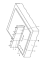
- FIG. 1 shows the entire coating apparatus 101 in the present embodiment.
- An enlarged perspective view of a part of the coating apparatus 101 is shown in FIG.
- the coating device 101 is a coating device for applying a solution to the main surface of an object having a main surface.
- the object is the substrate 6.
- the substrate 6 has a main surface 6a.
- the coating apparatus 101 is disposed above the main surface 6a and the support unit 5 that supports the substrate 6 as an object so that the main surface 6a faces upward, and can scan relatively in the first direction 91. And a plurality of possible heads 7.
- the plurality of heads 7 are arranged in a second direction 92 that is perpendicular to the first direction 91.
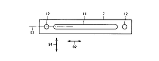
- FIG. 3 shows the arrangement of the solution outlets in each of the plurality of heads 7. These solution outlets are provided below each head 7.
- Each of the plurality of heads 7 includes a slit 11 extending in the second direction 92, and one or more ejection amount adjustment holes 12 disposed near each end of the slit 11.
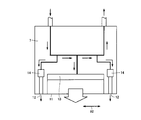
- each head 7 includes a slit pressurizing unit 13 for discharging the solution from the slit 11, and a discharge amount adjusting hole driving unit 14 for discharging the solution from the discharge amount adjusting hole 12.
- Have The discharge amount adjusting hole driving unit 14 can determine the discharge amount of the solution independently of the slit pressurizing unit 13.
- the support portion 5 includes a table 3 and support pins 4.
- the support part 5 is for supporting the board
- the table 3 is placed on the base 1 via the rail 2 and can be translated using the rail 2.
- the plurality of heads 7 do not necessarily need to move themselves, and may be stationary.
- the plurality of heads 7 can be scanned relative to the substrate 6 in the first direction 91 by the support unit 5 moving using the rails 5.
- the configuration in which the plurality of heads 7 are stationary and the support unit 5 moves is shown. Instead, the support unit 5 is stationary and the plurality of heads 7 move. May be.
- individual supply pipes 28 branched from the solution supply pipe 8 are connected to the plurality of heads 7, respectively.
- an individual recovery pipe 29 is connected to each head 7.
- the individual recovery pipe 29 is connected to the solution recovery pipe 9.
- the remainder of the solution supplied to each head 7 is recovered through the individual recovery pipe 29 and the solution recovery pipe 9.
- the valve in the middle of the piping is not shown in FIG. 1, it is preferable that the valve is actually provided in various places in practice.
- the discharge amount adjusting hole driving unit 14 may also be configured by a known technique.
- the discharge amount adjusting hole driving unit 14 may include a piezoelectric element.
- the coating device 101 in the present embodiment is Each of the heads 7 has one or more discharge amount adjusting holes 12 disposed in the vicinity of each end of the slit 11, and the discharge amount adjusting hole driving unit 14 is independent of the slit pressurizing unit 13. Since the discharge amount of the solution in the adjustment hole 12 can be determined, the heads 7 can be adjusted by finely adjusting the amount of the solution discharged from the discharge amount adjustment hole 12 by the discharge amount adjustment hole driving unit 14. The solution can be applied uniformly and accurately even at the boundary between the two.
- the discharge amount adjusting hole 12 is preferably disposed on an extension line 93 of the slit 11. This is because such a configuration makes it easy to create a head.
- a member provided with a groove corresponding to the slit 11 and the discharge amount adjusting hole 12 and a member not provided with a groove are prepared, and these members are bonded to each other so that the groove is on the inside. Can be created.
- Discharge amount adjustment hole 12 should just be arranged 1 or more near each end of slit 11. In the example shown in FIG. 3, only one discharge amount adjusting hole 12 is provided in the vicinity of one end of the slit 11, but for example, a head 7 e shown in FIG. Two discharge amount adjusting holes 12 may be provided in the vicinity.
- the arrangement is not limited to the arrangement along the extension line 93 of the slit 11 as shown in FIG.
- the plurality of discharge amount adjustment holes 12 may be arranged in a direction perpendicular to the extension line 93 or in a direction obliquely intersecting the extension line 93.
- the discharge amount adjusting hole 12 may be arranged at a position deviating from the extension line 93 of the slit 11 in the first direction 91.
- the discharge amount adjusting hole 12 is arranged at a position off the extension line 93 of the slit 11, so that it does not interfere with the slit 11. Since the distance between them can be reduced, the continuity of coating can be improved, which is convenient.
- the discharge amount adjusting holes 12 are provided at positions shifted to the same side at both ends of the slit 11, but different sides at both ends of the slit 11 as in the head 7g shown in FIG.
- the discharge amount adjusting hole 12 may be provided at a position deviated from the above position.
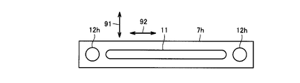
- the discharge amount adjusting hole may have a diameter larger than the width of the slit 11.
- the head 7h has a discharge amount adjusting hole 12h having a large diameter.
- the head 7h is obtained by enlarging the diameter of the discharge amount adjusting hole in the head 7 shown in FIG. 3, and the idea of increasing the diameter of the discharge amount adjusting hole in this way is shown in FIGS. They may be employed in the configurations shown in FIG.
- the discharge amount adjusting hole 12h in FIG. 8 is circular, it may have a shape other than circular. For example, it may be a rectangle, an oval, or a line.
- the discharge amount adjusting hole is formed in an oval shape or a linear shape, it is preferable to provide the first direction 91 so as to extend in the longitudinal direction because it does not interfere with the arrangement of the slits 11.
- FIG. 9 shows the arrangement of the plurality of heads 7 as viewed from below.
- Slit 11 discharge amount adjustment hole 12, discharge amount adjustment hole 12, slit 11, discharge amount adjustment hole 12, discharge amount adjustment hole 12, slit 11, the discharge amount adjusting hole 12, the discharge amount adjusting hole 12, the discharge amount adjusting hole 12, the discharge amount adjusting hole 12, the discharge amount adjusting hole 12, the discharge amount adjusting hole 12, and so on.
- a gap A is generated between the slits 11, but two discharge amount adjusting holes 12 are arranged in each gap A.
- the solution can be made uniform even in the gap A between the heads 7. Can be applied.
- the plurality of heads 7 are preferably arranged in a staggered manner.
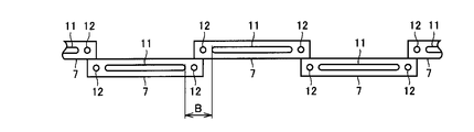
- two discharge amount adjusting holes 12 are arranged in the gap B between the slits 11.
- the gap B of the slit 11 can be made shorter than the gap A shown in FIG. Is easier to do.
- each head may have a configuration in which a plurality of ejection amount adjustment holes are provided in the vicinity of each end of the slit, and a plurality of heads having such a configuration may be arranged in a staggered manner.
- the present invention can be used for a coating apparatus.
Landscapes
- Coating Apparatus (AREA)
Abstract
塗布装置(101)は、基板(6)の主表面(6a)の上方に配置され、第1の方向に相対的に走査することができる複数のヘッド(7)を備え、複数のヘッド(7)は、第1の方向とは垂直な第2の方向(92)に並ぶように配列されている。各ヘッド(7)は、第2の方向(92)に延在するスリット(11)と、スリット(11)の各端の近傍に配置された吐出量調節穴(12)と、スリット(11)から溶液を吐出するためのスリット加圧部と、吐出量調節穴(12)から溶液を吐出するための吐出量調節穴駆動部とを有する。吐出量調節穴駆動部は、スリット加圧部とは独立して、溶液の吐出量を定めることができる。
Description
本発明は、塗布装置に関するものである。ここでいう「塗布装置」は、特に、対象物の主表面に溶液を塗布するための装置である。
液晶表示装置や半導体装置の製造方法においては、ガラス基板や半導体基板の表面に各種の薄膜を形成するための成膜工程が行なわれる。ここでいう「薄膜」とは、たとえば配向膜、レジスト膜などである。これらの薄膜は「機能性薄膜」と総称される場合もある。これらの薄膜の成膜工程として、溶液をインクジェット方式などにより基板表面に塗布する場合がある。インクジェット方式の場合、溶液を吐出することができるヘッドを基板表面に沿って走査させることが一般的である。そのような技術の一例は、特開2003-80130号公報(特許文献1)に示されている。
基板が大型である場合には複数のヘッドを並べて配置し、複数のヘッドが一斉に基板表面に沿って走査することとなる。そのような技術の一例は、特開2004-314012号公報(特許文献2)に示されている。複数のヘッドを並べて配置したものを用いれば広い面積の主表面にすばやく塗布することができる。
基板表面に溶液を塗布して成膜する場合、結果的に得られる膜が高い精度で均一な厚みを有することが求められる。特許文献1に示されるように多数の点状の孔を設けたヘッドを用いた場合、いずれかの孔において目詰まりが生じる確率が高くなってしまう。一部の孔に目詰まりが生じた場合、塗布結果にはムラが生じてしまう。
特許文献2では点状の孔の代わりにスリットを設けたヘッドが用いられている。このような複数のヘッドを並べて配置したものを用いる場合、ヘッド同士の境目では、特許文献2に示されているようにスリット同士をオーバラップさせて配置することも考えられるが、その場合、他の部分に比べてスリット同士がオーバラップした部分では、基板表面に供給される溶液の量が多くなってしまい、均一な厚みではなくなってしまう。また、オーバラップさせないように配置した場合には、ヘッド同士の境目においては他の部分に比べて基板表面に供給される溶液の量が少なくなってしまうので、結果的に得られる膜が均一な厚みではなくなってしまう。
そこで、本発明は、複数のヘッドを用いて、平坦な主表面を有する対象物の前記主表面に溶液を塗布する際に、精度良く均一な厚みとすることができるような塗布装置を提供することを目的とする。
上記目的を達成するため、本発明に基づく塗布装置は、主表面を有する対象物の上記主表面に溶液を塗布するための塗布装置であって、上記対象物を上記主表面が上側を向くように支持する支持部と、上記主表面の上方に配置され、第1の方向に相対的に走査することができる複数のヘッドとを備え、上記複数のヘッドは、上記第1の方向とは垂直な第2の方向に並ぶように配列されており、上記複数のヘッドの各々は、上記第2の方向に延在するスリットと、上記スリットの各端の近傍に1以上配置された吐出量調節穴と、上記スリットから上記溶液を吐出するためのスリット加圧部と、上記吐出量調節穴から上記溶液を吐出するための吐出量調節穴駆動部とを有し、上記吐出量調節穴駆動部は、上記スリット加圧部とは独立して上記溶液の吐出量を定めることが可能となっている。
本発明によれば、各ヘッドのスリットの各端の近傍に1以上配置された吐出量調節穴とを有し、かつ、吐出量調節穴駆動部は、スリット加圧部とは独立して吐出量調節穴における前記溶液の吐出量を定めることが可能となっているので、吐出量調節穴から吐出される溶液の量を吐出量調節穴駆動部によって微調整することによって、ヘッド同士の境目においても溶液を精度良く均一に塗布することができる。
(実施の形態1)
図1~図4を参照して、本発明に基づく実施の形態1における塗布装置について説明する。図1に本実施の形態における塗布装置101の全体を示す。塗布装置101の一部を拡大した斜視図を図2に示す。この塗布装置101は、主表面を有する対象物の前記主表面に溶液を塗布するための塗布装置である。本実施の形態で示す例では、対象物は基板6である。基板6は主表面6aを有する。塗布装置101は、対象物としての基板6を主表面6aが上側を向くように支持する支持部5と、主表面6aの上方に配置され、第1の方向91に相対的に走査することができる複数のヘッド7とを備える。複数のヘッド7は、第1の方向91とは垂直な第2の方向92に並ぶように配列されている。図3に複数のヘッド7の各々における溶液出口の配置を示す。これらの溶液出口は各ヘッド7の下側に設けられている。複数のヘッド7の各々は、第2の方向92に延在するスリット11と、スリット11の各端の近傍に1以上配置された吐出量調節穴12とを有する。図4に示すように、各ヘッド7は、スリット11から前記溶液を吐出するためのスリット加圧部13と、吐出量調節穴12から前記溶液を吐出するための吐出量調節穴駆動部14とを有する。吐出量調節穴駆動部14は、スリット加圧部13とは独立して前記溶液の吐出量を定めることが可能となっている。
図1~図4を参照して、本発明に基づく実施の形態1における塗布装置について説明する。図1に本実施の形態における塗布装置101の全体を示す。塗布装置101の一部を拡大した斜視図を図2に示す。この塗布装置101は、主表面を有する対象物の前記主表面に溶液を塗布するための塗布装置である。本実施の形態で示す例では、対象物は基板6である。基板6は主表面6aを有する。塗布装置101は、対象物としての基板6を主表面6aが上側を向くように支持する支持部5と、主表面6aの上方に配置され、第1の方向91に相対的に走査することができる複数のヘッド7とを備える。複数のヘッド7は、第1の方向91とは垂直な第2の方向92に並ぶように配列されている。図3に複数のヘッド7の各々における溶液出口の配置を示す。これらの溶液出口は各ヘッド7の下側に設けられている。複数のヘッド7の各々は、第2の方向92に延在するスリット11と、スリット11の各端の近傍に1以上配置された吐出量調節穴12とを有する。図4に示すように、各ヘッド7は、スリット11から前記溶液を吐出するためのスリット加圧部13と、吐出量調節穴12から前記溶液を吐出するための吐出量調節穴駆動部14とを有する。吐出量調節穴駆動部14は、スリット加圧部13とは独立して前記溶液の吐出量を定めることが可能となっている。
図1に示すように、支持部5はテーブル3と支持ピン4とを含む。支持部5は基板6を水平に支持するためのものである。テーブル3は、ベース1の上にレール2を介して載置されており、レール2を利用して平行移動することができる。この構成においては、複数のヘッド7自体は必ずしも自ら移動する必要はなく、静止していてもよい。複数のヘッド7は、支持部5がレール5を利用して移動することによって、基板6に対して第1の方向91に関する相対的な走査が可能となっている。図1に示した例では、複数のヘッド7が静止していて支持部5が移動する構成を示したが、その代わりに、支持部5が静止して複数のヘッド7が移動する構成であってもよい。
図1に示すように、複数のヘッド7に対しては、溶液供給配管8から枝分かれした個別供給配管28がそれぞれ接続されている。各ヘッド7には個別供給配管28の他に個別回収配管29が接続されている。個別回収配管29は溶液回収配管9に接続されている。各ヘッド7に供給された溶液のうち余ったものは個別回収配管29および溶液回収配管9を通じて回収されることとなっている。図1では配管の途中における弁を図示していないが、実際には弁が各所に適宜設けられていることが好ましい。
図4に示すスリット加圧部13は、溶液を塗布するための公知技術による構成であってよい。たとえば圧電素子を備えていてよい。吐出量調節穴駆動部14も公知技術による構成であってよい。吐出量調節穴駆動部14は圧電素子を備えていてよい。
複数のヘッドを並べて配置した塗布装置においては、ヘッド同士の境目において溶液の塗布状況が他の部位に比べて均一となるか否かが問題となるが、本実施の形態における塗布装置101は、各ヘッド7のスリット11の各端の近傍に1以上配置された吐出量調節穴12とを有し、かつ、吐出量調節穴駆動部14は、スリット加圧部13とは独立して吐出量調節穴12における前記溶液の吐出量を定めることが可能となっているので、吐出量調節穴12から吐出される溶液の量を吐出量調節穴駆動部14によって微調整することによって、ヘッド7同士の境目においても溶液を精度良く均一に塗布することができる。
図3に示すように、吐出量調節穴12は、スリット11の延長線93上に配置されていることが好ましい。このように配置された構成であれば、ヘッドの作成が容易となるからである。たとえばスリット11および吐出量調節穴12に対応する溝を設けた部材と、溝を設けない部材とを用意し、これらの部材を、前記溝が内側になるように互いに貼り合わせることによって、ヘッド7を作成することができる。
吐出量調節穴12は、スリット11の各端の近傍に1以上配置されていればよい。図3に示した例では、スリット11の1つの端の近傍には吐出量調節穴12は1個のみ設けられているが、たとえば図5に示すヘッド7eのように、スリット11の各端の近傍にそれぞれ吐出量調節穴12を2個ずつ設けてもよい。スリット11の各端の近傍に複数個ずつ設ける場合、その並び方は、図5に示したように、スリット11の延長線93に沿って並べた配置に限らない。複数の吐出量調節穴12は、延長線93に対して垂直な方向や、延長線93に対して斜めに交差する方向に並べてもよい。
図6に示すヘッド7fのように、吐出量調節穴12は、スリット11の延長線93上から第1の方向91に外れた位置に配置されていてもよい。この構成を採用することにより、複数のヘッドを一直線上に並べた場合に、吐出量調節穴12はスリット11の延長線93上から外れた位置に配置されているので邪魔とならず、スリット11同士の距離を近づけることができるので、塗布の連続性を高めることができ、好都合である。図6に示したヘッド7fではスリット11の両端において同じ側にずれた位置に吐出量調節穴12が設けられていたが、図7に示すヘッド7gのように、スリット11の両端においてそれぞれ異なる側にずれた位置に吐出量調節穴12が設けられていてもよい。
図8に示すヘッド7hのように、吐出量調節穴は、スリット11の幅より大きな径を有することとしてもよい。ヘッド7hは径が大きな吐出量調節穴12hを有している。ヘッド7hは、図3に示したヘッド7において吐出量調節穴の径を拡大したものであるが、このように吐出量調節穴の径を大きくするという発想は、図5、図6、図7にそれぞれ示した構成において採用してもよい。図8における吐出量調節穴12hは円形となっているが、円形以外の形状であってもよい。たとえば四角形、長円形であっでもよく、線状であってもよい。吐出量調節穴を長円形または線状とする場合、第1の方向91を長手方向として延在するように設ければ、スリット11の配置にとって邪魔とならないので好ましい。
図2に示した例では、3つのヘッド7が一直線上に並んでいるが、より多くの数のヘッド7を一直線上に並べた場合、スリット11と吐出量調節穴12との並びの関係は、図9に示すようになる。図9は複数のヘッド7の配列を下方から見たところである。図9に示した例では、溶液出口の並び方に注目すれば、…、スリット11、吐出量調節穴12、吐出量調節穴12、スリット11、吐出量調節穴12、吐出量調節穴12、スリット11、吐出量調節穴12、吐出量調節穴12、スリット11、吐出量調節穴12、吐出量調節穴12、…と繰り返すように並ぶこととなる。この場合、スリット11同士の間にそれぞれ間隙Aが生じるが、各間隙Aにはそれぞれ2つの吐出量調節穴12が配置されることとなる。この場合、上述したように、吐出量調節穴駆動部14によって吐出量調節穴12から吐出される溶液の量を微調整することによって、ヘッド7同士の境目の間隙Aにおいても溶液を精度良く均一に塗布することができる。
図10に示す例のように、複数のヘッド7は、千鳥状に配列されていることが好ましい。このように配置した場合、スリット11同士の間隙Bにはそれぞれ2つの吐出量調節穴12が配置されている。図10に示したように、複数のヘッド7を千鳥状に配列した場合、図9に示した間隙Aに比べてスリット11の間隙Bを短くすることができるので、吐出量調節穴12による調整が行ないやすくなる。
実施の形態1における塗布装置101を出発点としてここまでいくつかの変形例について説明したが、これらの変形例はそれぞれ単独で採用するだけでなく、複数の変形例を組み合わせて採用してもよい。たとえば、各ヘッドを、スリットの各端の近傍にそれぞれ吐出量調節穴が複数設けられた構成とし、そのような構成を備える複数のヘッドを千鳥状に配列してもよい。
なお、今回開示した上記実施の形態はすべての点で例示であって制限的なものではない。本発明の範囲は上記した説明ではなくて請求の範囲によって示され、請求の範囲と均等の意味および範囲内でのすべての変更を含むものである。
本発明は、塗布装置に利用することができる。
1 ベース、2 レール、3 テーブル、4 支持ピン、5 支持部、6 基板、6a 主表面、7,7e,7f,7g,7h ヘッド、8 溶液供給配管、9 溶液回収配管、11 スリット、12,12h 吐出量調節穴、13 スリット加圧部、14 吐出量調節穴駆動部、28 個別供給配管、29 個別回収配管、91 第1の方向、92 第2の方向、93 延長線、101 塗布装置。
Claims (5)
- 主表面(6a)を有する対象物の前記主表面に溶液を塗布するための塗布装置(101)であって、
前記対象物を前記主表面が上側を向くように支持する支持部(5)と、
前記主表面の上方に配置され、第1の方向(91)に相対的に走査することができる複数のヘッド(7)とを備え、
前記複数のヘッドは、前記第1の方向とは垂直な第2の方向(92)に並ぶように配列されており、
前記複数のヘッドの各々は、前記第2の方向に延在するスリット(11)と、前記スリットの各端の近傍に1以上配置された吐出量調節穴(12)と、前記スリットから前記溶液を吐出するためのスリット加圧部(13)と、前記吐出量調節穴から前記溶液を吐出するための吐出量調節穴駆動部(14)とを有し、
前記吐出量調節穴駆動部は、前記スリット加圧部とは独立して前記溶液の吐出量を定めることが可能となっている、塗布装置。 - 前記吐出量調節穴は、前記スリットの延長線上に配置されている、請求項1に記載の塗布装置。
- 前記吐出量調節穴は、前記スリットの延長線上から前記第1の方向に外れた位置に配置されている、請求項1に記載の塗布装置。
- 前記吐出量調節穴は、前記スリットの幅より大きな径を有する、請求項1から3のいずれかに記載の塗布装置。
- 前記複数のヘッドは、千鳥状に配列されている、請求項1から4のいずれかに記載の塗布装置。
Applications Claiming Priority (2)
| Application Number | Priority Date | Filing Date | Title |
|---|---|---|---|
| JP2010-091963 | 2010-04-13 | ||
| JP2010091963A JP2013128860A (ja) | 2010-04-13 | 2010-04-13 | 塗布装置 |
Publications (1)
| Publication Number | Publication Date |
|---|---|
| WO2011129194A1 true WO2011129194A1 (ja) | 2011-10-20 |
Family
ID=44798572
Family Applications (1)
| Application Number | Title | Priority Date | Filing Date |
|---|---|---|---|
| PCT/JP2011/057773 Ceased WO2011129194A1 (ja) | 2010-04-13 | 2011-03-29 | 塗布装置 |
Country Status (2)
| Country | Link |
|---|---|
| JP (1) | JP2013128860A (ja) |
| WO (1) | WO2011129194A1 (ja) |
Cited By (1)
| Publication number | Priority date | Publication date | Assignee | Title |
|---|---|---|---|---|
| JP2015173183A (ja) * | 2014-03-11 | 2015-10-01 | 東京応化工業株式会社 | 塗布装置、基板処理装置、塗布方法及び基板処理方法 |
Citations (3)
| Publication number | Priority date | Publication date | Assignee | Title |
|---|---|---|---|---|
| JP2003080130A (ja) * | 2001-09-11 | 2003-03-18 | Shibaura Mechatronics Corp | 塗布装置及び塗布方法 |
| JP2004274054A (ja) * | 2003-03-06 | 2004-09-30 | Samsung Electronics Co Ltd | 感光物質塗布装置 |
| JP2004314012A (ja) * | 2003-04-18 | 2004-11-11 | Shibaura Mechatronics Corp | 塗布装置 |
-
2010
- 2010-04-13 JP JP2010091963A patent/JP2013128860A/ja not_active Withdrawn
-
2011
- 2011-03-29 WO PCT/JP2011/057773 patent/WO2011129194A1/ja not_active Ceased
Patent Citations (3)
| Publication number | Priority date | Publication date | Assignee | Title |
|---|---|---|---|---|
| JP2003080130A (ja) * | 2001-09-11 | 2003-03-18 | Shibaura Mechatronics Corp | 塗布装置及び塗布方法 |
| JP2004274054A (ja) * | 2003-03-06 | 2004-09-30 | Samsung Electronics Co Ltd | 感光物質塗布装置 |
| JP2004314012A (ja) * | 2003-04-18 | 2004-11-11 | Shibaura Mechatronics Corp | 塗布装置 |
Cited By (1)
| Publication number | Priority date | Publication date | Assignee | Title |
|---|---|---|---|---|
| JP2015173183A (ja) * | 2014-03-11 | 2015-10-01 | 東京応化工業株式会社 | 塗布装置、基板処理装置、塗布方法及び基板処理方法 |
Also Published As
| Publication number | Publication date |
|---|---|
| JP2013128860A (ja) | 2013-07-04 |
Similar Documents
| Publication | Publication Date | Title |
|---|---|---|
| JP5492289B2 (ja) | 成膜装置および成膜方法 | |
| JP2008544333A (ja) | フラットパネルディスプレイ用インクジェット印刷システム及び方法 | |
| US20090284570A1 (en) | Printer head and printing method having the same | |
| JP2010279944A (ja) | ペースト塗布方法、及びその方法により形成されたペーストパターンを有する基板 | |
| JPWO2016104126A1 (ja) | インクジェットヘッドの取付構造、キャリッジ及びインクジェット記録装置 | |
| TWI688431B (zh) | 膜形成方法及膜形成裝置 | |
| KR20200131421A (ko) | 약액 토출 장치 및 약액 토출 방법 | |
| KR101074666B1 (ko) | 페이스트 디스펜서 및 페이스트 도포방법 | |
| WO2011129194A1 (ja) | 塗布装置 | |
| JP4702287B2 (ja) | 液滴吐出装置、機能膜形成方法、液晶配向膜形成装置及び液晶表示装置の液晶配向膜形成方法 | |
| KR101204067B1 (ko) | 스테이지 장치 | |
| JP2007052435A5 (ja) | ||
| JP2011054790A (ja) | 基板の処理装置及び処理方法 | |
| KR102440567B1 (ko) | 기판 처리 장치 및 방법 | |
| CN101160181B (zh) | 涂敷装置及涂敷方法 | |
| KR20110042736A (ko) | 페이스트 디스펜서 및 그 제어방법 | |
| KR20070011926A (ko) | 잉크젯 헤드의 정렬 장치 및 이를 포함하는 잉크젯 배향막인쇄 장치, 그리고 이를 이용한 잉크젯 헤드의 정렬 방법 | |
| JP2007050662A (ja) | 構造体の製造方法及び構造体、並びに液滴吐出装置 | |
| KR101723376B1 (ko) | 유체토출장치의 헤드유닛 | |
| KR20230058753A (ko) | 잉크젯 프린트 시스템 및 이를 이용한 잉크젯 프린팅 방법 | |
| JP2018083365A (ja) | 液体吐出ヘッドおよびその製造方法 | |
| JP6636392B2 (ja) | 膜パターン描画方法 | |
| JP4997851B2 (ja) | ヘッドユニットおよび液状体吐出装置 | |
| CN101642745B (zh) | 带有以镜像构形的方式布置的头单元的涂布机 | |
| KR20100055784A (ko) | 에어 분사 장치 |
Legal Events
| Date | Code | Title | Description |
|---|---|---|---|
| 121 | Ep: the epo has been informed by wipo that ep was designated in this application |
Ref document number: 11768715 Country of ref document: EP Kind code of ref document: A1 |
|
| NENP | Non-entry into the national phase |
Ref country code: DE |
|
| 122 | Ep: pct application non-entry in european phase |
Ref document number: 11768715 Country of ref document: EP Kind code of ref document: A1 |
|
| NENP | Non-entry into the national phase |
Ref country code: JP |