WO2011129093A1 - Dispositif d'application de film de polarisation et système de fabrication de dispositif d'affichage à cristaux liquides le comprenant - Google Patents
Dispositif d'application de film de polarisation et système de fabrication de dispositif d'affichage à cristaux liquides le comprenant Download PDFInfo
- Publication number
- WO2011129093A1 WO2011129093A1 PCT/JP2011/002132 JP2011002132W WO2011129093A1 WO 2011129093 A1 WO2011129093 A1 WO 2011129093A1 JP 2011002132 W JP2011002132 W JP 2011002132W WO 2011129093 A1 WO2011129093 A1 WO 2011129093A1
- Authority
- WO
- WIPO (PCT)
- Prior art keywords
- substrate
- polarizing film
- transport mechanism
- reversing
- unit
- Prior art date
Links
Images


Classifications
-
- G—PHYSICS
- G02—OPTICS
- G02F—OPTICAL DEVICES OR ARRANGEMENTS FOR THE CONTROL OF LIGHT BY MODIFICATION OF THE OPTICAL PROPERTIES OF THE MEDIA OF THE ELEMENTS INVOLVED THEREIN; NON-LINEAR OPTICS; FREQUENCY-CHANGING OF LIGHT; OPTICAL LOGIC ELEMENTS; OPTICAL ANALOGUE/DIGITAL CONVERTERS
- G02F1/00—Devices or arrangements for the control of the intensity, colour, phase, polarisation or direction of light arriving from an independent light source, e.g. switching, gating or modulating; Non-linear optics
- G02F1/01—Devices or arrangements for the control of the intensity, colour, phase, polarisation or direction of light arriving from an independent light source, e.g. switching, gating or modulating; Non-linear optics for the control of the intensity, phase, polarisation or colour
- G02F1/13—Devices or arrangements for the control of the intensity, colour, phase, polarisation or direction of light arriving from an independent light source, e.g. switching, gating or modulating; Non-linear optics for the control of the intensity, phase, polarisation or colour based on liquid crystals, e.g. single liquid crystal display cells
- G02F1/133—Constructional arrangements; Operation of liquid crystal cells; Circuit arrangements
- G02F1/1333—Constructional arrangements; Manufacturing methods
- G02F1/1335—Structural association of cells with optical devices, e.g. polarisers or reflectors
- G02F1/133528—Polarisers
-
- G—PHYSICS
- G02—OPTICS
- G02B—OPTICAL ELEMENTS, SYSTEMS OR APPARATUS
- G02B5/00—Optical elements other than lenses
- G02B5/30—Polarising elements
- G02B5/3025—Polarisers, i.e. arrangements capable of producing a definite output polarisation state from an unpolarised input state
- G02B5/3033—Polarisers, i.e. arrangements capable of producing a definite output polarisation state from an unpolarised input state in the form of a thin sheet or foil, e.g. Polaroid
-
- G—PHYSICS
- G02—OPTICS
- G02F—OPTICAL DEVICES OR ARRANGEMENTS FOR THE CONTROL OF LIGHT BY MODIFICATION OF THE OPTICAL PROPERTIES OF THE MEDIA OF THE ELEMENTS INVOLVED THEREIN; NON-LINEAR OPTICS; FREQUENCY-CHANGING OF LIGHT; OPTICAL LOGIC ELEMENTS; OPTICAL ANALOGUE/DIGITAL CONVERTERS
- G02F1/00—Devices or arrangements for the control of the intensity, colour, phase, polarisation or direction of light arriving from an independent light source, e.g. switching, gating or modulating; Non-linear optics
- G02F1/01—Devices or arrangements for the control of the intensity, colour, phase, polarisation or direction of light arriving from an independent light source, e.g. switching, gating or modulating; Non-linear optics for the control of the intensity, phase, polarisation or colour
- G02F1/13—Devices or arrangements for the control of the intensity, colour, phase, polarisation or direction of light arriving from an independent light source, e.g. switching, gating or modulating; Non-linear optics for the control of the intensity, phase, polarisation or colour based on liquid crystals, e.g. single liquid crystal display cells
- G02F1/1303—Apparatus specially adapted to the manufacture of LCDs
Definitions
- the present invention relates to a polarizing film laminating apparatus and a liquid crystal display manufacturing system including the same.
- liquid crystal display devices have been widely manufactured.
- a polarizing film is bonded to a substrate (liquid crystal panel) used in a liquid crystal display device in order to control transmission or blocking of light.
- the polarizing film is bonded so that the absorption axes thereof are orthogonal.
- Patent Document 1 discloses an optical display device manufacturing system.
- the said manufacturing system rotates a board
- optical film polarizing film
- the conventional apparatus has the following problems.
- the work is usually performed in a clean room in order to prevent foreign matters such as dust from entering the bonding surface.
- air is rectified. This is because it is necessary to bond the polarizing film in a state in which rectification is performed on the substrate in a downflow in order to suppress the yield reduction due to the foreign matter.
- the manufacturing system of Patent Document 1 has a configuration in which a polarizing film is bonded to the substrate from the upper surface and the lower surface.
- a demerit that airflow (downflow) is hindered by the polarizing film and the rectification environment to the substrate is deteriorated.
- FIGS. 10A and 10B show air velocity vectors in the top-paste type manufacturing system. In FIG.
- area A is an area where an unwinding part for unwinding the polarizing film is installed
- area B is an area through which the polarizing film mainly passes
- area C is peeled off from the polarizing film. This is an area in which a take-up unit or the like for winding the film is installed.
- clean air is supplied from a HEPA (High Efficiency Particulate Air) filter 40.
- HEPA High Efficiency Particulate Air
- FIG. 10A since the grating 41 through which clean air can pass is installed, the airflow can move in the vertical direction via the grating 41.
- FIG. 10B since the grating 41 is not installed, the airflow moves along the floor after contacting the floor at the bottom of FIG. 10B.
- the areas A to C are arranged on the 2F (second floor) portion, and the clean air from the HEPA filter 40 is blocked by the polarizing film. Therefore, it is difficult to generate an airflow in the vertical direction with respect to the substrate passing through the 2F portion.
- the airflow vector in the horizontal direction is large (vector density is high). That is, it can be said that the rectification environment has deteriorated.
- the objective is to provide the manufacturing system of a polarizing film bonding apparatus and a liquid crystal display device provided with the same which do not disturb a rectification environment. is there.
- the polarizing film laminating device of the present invention transports a rectangular substrate with the long side or the short side along the transport direction.
- a first substrate transport mechanism, a first bonding unit for bonding a polarizing film to the lower surface of the substrate in the first substrate transport mechanism, and the substrate transported by the first substrate transport mechanism are reversed to A reversing mechanism disposed in the two-substrate transport mechanism, a second substrate transport mechanism that transports the substrate with a short side or a long side along the transport direction, and polarization on the lower surface of the substrate in the second substrate transport mechanism
- substrate conveyance mechanism are arrange
- the said inversion mechanism is A suction part for sucking the substrate, and a suction part connected to the suction part.
- a substrate reversing unit for reversing the substrate wherein the substrate reversing unit is (1) while reversing the substrate in the first substrate transport mechanism (1) so as to draw a curve (3) ) It is arranged to be arranged on the second substrate transport mechanism so that the long side or the short side along the transport direction of the first substrate transport mechanism is along the direction orthogonal to the transport direction.
- a polarizing film is bonded to the lower surface of a board
- substrate conveyance mechanism is reversed by the inversion mechanism, and the conveyance direction of a 1st board
- the long side or the short side along the direction along the direction orthogonal to the transport direction can be arranged in the second substrate transport mechanism, and then the polarizing film is applied to the lower surface of the substrate by the second bonding unit.
- the bonding apparatus according to the present invention is very simple to install and is excellent in area efficiency.
- the bonding apparatus for the polarizing film of the present invention (second invention) is: A first substrate transport mechanism for transporting a rectangular substrate with a long side or a short side along the transport direction; A first bonding unit for bonding a polarizing film to the lower surface of the substrate in the first substrate transport mechanism; A substrate support device comprising a substrate support unit for supporting the substrate transported by the first substrate transport mechanism; A reversing mechanism provided with a substrate reversing unit that is connected to the substrate supporting unit and arranged to reverse the substrate supported by the substrate supporting unit; A second substrate transport mechanism that transports the substrate that is reversed by the reversing mechanism and that has the short side or the long side disposed along the transport direction; A polarizing film laminating apparatus including a second laminating unit for laminating a polarizing film on the lower surface of the substrate in the second substrate transport mechanism, The first substrate transport mechanism and the second substrate transport mechanism are arranged in the same direction, The reversing mechanism is transported by the second substrate transport mechanism from a
- the substrate transported in the first substrate transport mechanism is reversed by drawing an arc locus by rotating the substrate in the layout direction by a fixed angle range around the placement change axis changed by the placement changing unit in the placement direction of the substrate.
- the arrangement is changed so as to be along the substrate carrying direction in the second substrate carrying mechanism, and the second substrate carrying mechanism is arranged with respect to the second substrate carrying mechanism.
- the polarizing film laminating device of the present invention (third invention) according to claim 3 is:
- the reversing mechanism is configured such that the substrate reversing unit is connected to a reversing shaft unit including the reversing shaft rotatably disposed on the arrangement changing unit, and is rotated by a rotation driving source. Is.
- the bonding apparatus for the polarizing film of the present invention (fourth invention) according to claim 4 is:
- the reversing mechanism is configured such that the arrangement changing unit is disposed so as to be relatively rotatable on the substrate reversing unit connected to the reversing shaft unit including the reversing shaft, and is rotated by a rotation driving source. It is.
- the polarizing film laminating device of the present invention (the fifth invention) according to claim 5 is:
- the substrate support part of the substrate support device is constituted by a plurality of support members that sandwich and support both surfaces of the substrate transported by the first substrate transport mechanism.
- the pasting device for the polarizing film of the present invention (sixth invention) according to claim 6 is:
- the substrate support part of the substrate support device is configured by an adsorption member including an adsorption part that adsorbs the surface of the substrate conveyed by the first substrate conveyance mechanism.
- the bonding apparatus for the polarizing film of the present invention is:
- the substrate supporting device is disposed on a member connected to a substrate reversing unit that performs the reversing operation of the substrate, and a first supporting member and a first supporting member that enter the end portions of the first substrate transporting mechanism and the second substrate transporting mechanism. And by supporting the substrate transported from the first substrate transport mechanism between the first support member and the second support member by sandwiching the substrate by relative movement with the second support member, Supported by being sandwiched between the first support member and the second support member reversed by the substrate reversing part by the relative movement of the first support member and the second support member. The above-described substrate is released from the support by sandwiching and is placed on the end portion of the second substrate transport mechanism.
- the polarizing film laminating device of the present invention (eighth invention) according to claim 8 is:
- the end portions of the first substrate transport mechanism are divided into a plurality of portions in the width direction, and a plurality of first and second comb-like members that constitute the first and second support members between adjacent portions.
- a plurality of gaps into which the protrusions of the first substrate and the second substrate transport mechanism enter, and an end portion of the second substrate transport mechanism is divided into a plurality of portions in the transport direction and inverted between adjacent portions.
- a plurality of gaps into which a plurality of protrusions of the first and second comb-shaped members constituting the second support member enter are formed.
- the polarizing film laminating apparatus of the present invention (the ninth invention) according to claim 9 is:
- the first and second comb-like members having a plurality of protrusions constituting the first and second support members are configured to swing within a certain angle range with a part as a fulcrum. is there.
- a polarizing film laminating apparatus of the present invention (tenth invention) according to claim 10 is:
- the first and second comb-like members having a plurality of protrusions constituting the first and second support members are configured to be driven to swing by a swing drive mechanism. .
- the polarizing film laminating device of the present invention (11th invention) according to claim 11
- the swing drive mechanism includes a first swing drive mechanism that swings and drives the first comb-like member having a plurality of protrusions that constitute the first support member, and a second support member. It comprises a second swing drive mechanism that swings and drives the second comb-like member having a plurality of projecting portions.
- the polarizing film laminating device of the present invention (the twelfth invention) according to claim 12
- the first and second comb-like members having a plurality of projecting portions constituting the first and second support members are reciprocated so that the facing distance is changed by relatively approaching or separating in one direction. It is configured to be movable.
- the polarizing film laminating apparatus of the present invention (the thirteenth aspect) according to claim 13
- the first and second comb-like members having a plurality of protrusions constituting the first and second support members are configured to be driven by a linear drive mechanism and reciprocate. is there.
- the first substrate transport mechanism and the second substrate transport mechanism are arranged in a straight line, and the first substrate transport mechanism In the end portion on the second substrate transport mechanism side, two pairs of substrate placement portions and the above reversing mechanisms are provided along both directions parallel to the transport direction of the first substrate transport mechanism.
- a transfer means for transferring the substrate from the end portion to the substrate mounting portion, and the reversing mechanism reverses the substrate transferred to each of the substrate mounting portions and arranges it on the second substrate transfer mechanism. It is preferable to do.
- the substrate can be processed twice per unit time. Thereby, since many substrates can be reversed per unit time, the tact time is shortened. Furthermore, since the 1st board
- a first film transport mechanism and a second film transport mechanism for transporting the polarizing film are provided, and the first film is provided.
- the transport mechanism includes a plurality of unwinding portions for unwinding the polarizing film protected by the release film, a cutting portion for cutting the polarizing film, a removal portion for removing the release film from the polarizing film, and the removed release film.
- the second film transport mechanism includes a plurality of unwinding sections for unwinding the polarizing film protected by the release film, and a cutting section for cutting the polarizing film.
- the first substrate transport mechanism and the second group are provided.
- the transport mechanism is provided above the first film transport mechanism and the second film transport mechanism, and the first bonding section that bonds the polarizing film from which the release film has been removed to the substrate is the first film transport.
- each of the second bonding parts for bonding the polarizing film from which the release film has been removed to the substrate is between the second film transport mechanism and the second substrate transport mechanism. It is preferable that it is provided.
- the unwinding part and the winding part are provided in plural, when the remaining amount of the original film of the polarizing film in one unwinding part decreases, the other unwinding part is provided in the original film. It is possible to connect raw materials. As a result, the operation can be continued without stopping the unwinding of the polarizing film, and the production efficiency can be increased.
- the cleaning unit for cleaning the substrate before the polarizing film is bonded to the lower surface of the substrate by the first bonding unit.
- the first substrate transport mechanism preferably transports the substrate with the short side of the substrate along the transport direction.
- the substrate can be cleaned by the cleaning unit in a state where the long sides of the substrate are orthogonal to the substrate transport direction. That is, since the distance of the substrate along the transport direction can be reduced, the tact time required for cleaning can be further shortened. As a result, it is possible to provide a polarizing film laminating apparatus that is further excellent in production efficiency.
- the first film transport mechanism and the second film transport mechanism are unwound from the first unwinding section.
- the defect detection unit since it is possible to avoid the bonding between the polarizing film having a defect and the substrate, it is possible to increase the yield.
- the manufacturing system of the liquid crystal display device according to the eighteenth aspect of the present invention includes a bonding displacement between the polarizing film bonding apparatus and the substrate on which the polarizing film is bonded by the second bonding portion.
- a misalignment inspection apparatus for inspecting the film is provided.
- the presence / absence of sticking deviation is determined based on the inspection result by the sticking deviation inspection apparatus, and the polarizing film is determined based on the determination result. It is preferable to provide a sorting / conveying device for sorting the substrates to which the is bonded.
- the presence or absence of foreign matter is determined based on the inspection result by the bonded foreign matter automatic inspection device, and polarization is determined based on the determination result. It is preferable to provide a sorting / conveying device for sorting the substrates on which the films are bonded.
- substrate with which the polarizing film was bonded by the said 2nd bonding part was made.
- the apparatus is provided, and based on the inspection result by the sticking misalignment inspection apparatus and the inspection result by the sticking foreign matter automatic inspection apparatus, the presence or absence of sticking misalignment and foreign matter is determined. It is preferable to provide a sorting / conveying device for sorting the substrates.
- the first substrate transport mechanism and the second substrate transport mechanism are arranged in the same direction, and the reversing mechanism attracts the substrate.
- a substrate reversing unit that is connected to the suction unit and that inverts the substrate.
- the substrate reversing unit draws (1) a curve of the substrate in the first substrate transport mechanism.
- the substrate can be brought into a state in which the long side and the short side with respect to the reversing and transporting directions are changed by one operation by the reversing mechanism.
- a polarizing film can be bonded from the lower surface with respect to both surfaces of a board
- the operation of the reversing mechanism is a simple operation, the tact time is short. Therefore, it is possible to realize bonding with a short tact time.
- the first substrate transport mechanism and the second substrate transport mechanism are arranged in the same direction. That is, it does not have a complicated structure such as an L shape. Therefore, the bonding apparatus according to the first aspect of the present invention is very simple to install and also has an effect of being excellent in area efficiency.
- the reversing mechanism is transported by the reversing shaft for reversing the substrate reversing unit and the first substrate transporting mechanism so that the front surface of the substrate is the back surface.
- the substrate is rotated in a certain angle range around a placement change axis that is changed by the placement changer in the placement direction of the substrate that is transported in the second substrate transport mechanism from the placement direction of the substrate.
- the transferred substrate is reversed with a circular arc trajectory, and is arranged with respect to the second substrate transfer mechanism by changing the arrangement along the substrate transfer direction in the second substrate transfer mechanism.
- the reversing operation that draws a series of arc trajectories of the substrate reversing unit, the reversal of the substrate and the arrangement of the substrate along the second substrate transport mechanism are performed.
- the reversal of the substrate and the arrangement of the substrate along the second substrate transport mechanism are performed.
- the polarizing film laminating apparatus having the above-described configuration is the reversing shaft, wherein the reversing mechanism is rotatably disposed on the arrangement changing unit that is rotationally driven by the rotation driving source.
- the substrate reversing portion connected to the reversing shaft portion is rotated by the rotation driving source, so that the reversing operation draws a series of arc trajectories of the substrate reversing portion rotated by the rotation driving source. Since the arrangement of the substrate is changed so as to conform to the inversion of the substrate and the arrangement in the second substrate transport mechanism, the tact time is shortened, and the effect of enabling bonding with a short tact time is achieved.
- the reversing mechanism is the substrate reversing unit that is rotationally driven by the rotation driving source connected to the reversing shaft unit having the reversing shaft.
- the arrangement changing unit arranged so as to be relatively rotatable is rotationally driven by a rotational driving source, so that the substrate is rotated by a reversing operation that draws a series of arc trajectories of the substrate reversing unit that is rotationally driven by the rotational driving source. Since the arrangement of the substrate is changed so as to conform to the reversal and the arrangement in the second substrate transport mechanism, the tact time is shortened, and the effect of enabling bonding with a short tact time is achieved.
- the polarizing film laminating device of the fifth invention having the above-described configuration is the first invention by the plurality of support members constituting the substrate support portion of the substrate support device according to any one of the second to fourth inventions. Since both surfaces of the substrate transported by the substrate transport mechanism are sandwiched and supported, the substrate transported by the first substrate transport mechanism is securely supported and the inverted substrate is supported. In addition, there is an effect of ensuring the arrangement change.
- a polarizing film laminating device having the above-described configuration is the above-described suction member including the suction portion that constitutes the substrate support portion of the substrate support device according to any one of the second to fourth aspects. Since the surface of the substrate transported by the first substrate transport mechanism is adsorbed, it is possible to simplify the configuration of the substrate support portion, and to achieve weight reduction and high-speed rotation.
- the polarizing film laminating apparatus according to the seventh invention having the above-described configuration is disposed on a member connected to the substrate reversing unit that performs the reversing operation of the substrate. Due to the relative movement of the first support member and the second support member entering the end portions of the first substrate transport mechanism and the second substrate transport mechanism, the first support member and the second support member The substrate transported from the first substrate transport mechanism is supported by being sandwiched, and is reversed by the substrate reversing unit by the relative movement of the first support member and the second support member. The support supported by sandwiching the substrate supported by being sandwiched between the first support member and the second support member is released to the end of the second substrate transport mechanism.
- the substrate transported by the first substrate transport mechanism is sandwiched between the first support member and the second support member that have entered the end portion of the first substrate transport mechanism.
- the substrate reversing unit enables the reversal of the substrate, and the first support member and the second support member reversed by the substrate reversing unit.
- the substrate supported by being sandwiched in between is released from the support by the sandwiching and placed on the end of the second substrate transport mechanism, so that the substrate in the second substrate transport mechanism is There is an effect of enabling conveyance.
- the polarizing film laminating device of the eighth invention configured as described above is formed between adjacent portions of the plurality of divided portions in the width direction at the end of the first substrate transport mechanism in the third invention or the fourth invention.
- a plurality of protrusions of the first and second comb-shaped members constituting the inverted first and second support members in a plurality of gaps formed between adjacent portions of the plurality of divided portions in the transport direction Entered the inverted substrate That the support is released, by being mounted on an end portion of the second substrate transport mechanism, the effect of allowing bonding of the transfer and the polarizing film of the substrate in the second substrate transport mechanisms.
- the polarizing film laminating device having the above-described configuration is formed between a plurality of adjacent portions of the plurality of divided portions in the width direction at the end of the first substrate transport mechanism.
- a plurality of protrusions of the first and second comb-like members constituting the first and second support members enter the gap, and a plurality of at least one of the first and second comb-like members is entered.
- the protrusion swings in a certain angle range with a part as a fulcrum, the substrate transported from the first substrate transport mechanism is in contact with the plurality of protrusions of the first and second comb-shaped members.
- the inverted first and second A plurality of protrusions of the first and second comb-shaped members constituting the holding member enter, and at least one of the plurality of protrusions of the first and second comb-shaped members has a fixed angle with one end as a fulcrum.
- the polarizing film laminating apparatus having the above-mentioned configuration is the ninth aspect, wherein the first and second comb-shaped members are provided with a plurality of protrusions constituting the first and second support members.
- the substrate transported from the first substrate transport mechanism is sandwiched between the plurality of protrusions of the first and second comb-shaped members.
- the second substrate can be reliably supported by being attached, and the support by the sandwiching of the inverted substrate is released and placed on the end of the second substrate transport mechanism.
- the polarizing film laminating apparatus is the tenth aspect of the present invention, wherein the first swing drive mechanism constituting the swing drive mechanism is a plurality of the first support member.
- the first comb-like member provided with the protrusion is driven to swing, and the second swing drive mechanism constituting the swing drive mechanism includes a plurality of protrusions constituting the second support member.
- the substrate transported from the first substrate transport mechanism is sandwiched between the plurality of protrusions of the first and second comb-shaped members.
- the second substrate can be reliably supported by being attached, and the support by the sandwiching of the inverted substrate is released and placed on the end of the second substrate transport mechanism.
- the substrate is transported by the transport mechanism and the polarization An effect of allowing bonding of Lum.
- a polarizing film laminating apparatus having the above-described configuration is the eighth aspect of the present invention, wherein a plurality of the polarizing film laminating devices are formed between adjacent portions of a plurality of divided portions in the width direction at the end of the first substrate transport mechanism.
- a plurality of protrusions of the first and second comb-like members constituting the first and second support members enter the gap, and a plurality of at least one of the first and second comb-like members is entered.
- the projecting portion relatively approaches in one direction, the substrate transported from the first substrate transport mechanism is sandwiched between the plurality of projecting portions of the first and second comb-shaped members.
- the plurality of gaps formed between adjacent portions of the plurality of divided portions in the transport direction at the end of the second substrate transport mechanism are inverted.
- the first and second support members are configured.
- the support by sandwiching the inverted substrate is released and placed on the end of the second substrate transport mechanism, so that the substrate can be transported and the polarizing film can be bonded in the second substrate transport mechanism. It has the effect of making it.
- the polarizing film laminating device of the thirteenth aspect of the present invention having the above-described configuration is the twelfth aspect of the present invention, wherein the linear driving mechanism includes the plurality of protrusions constituting the first and second support members. And the second comb-like member is linearly driven and reciprocates so that the substrate transported from the first substrate transport mechanism is between the plurality of protrusions of the first and second comb-like members. In addition to the effect that the substrate is securely supported by being sandwiched, the support by the sandwiching of the inverted substrate is released and placed on the end of the second substrate transport mechanism, whereby the first There exists an effect of enabling conveyance of the said board
- substrate support apparatus and inversion mechanism in another Example. It is explanatory drawing for demonstrating the operation
- the first and second substrate support members are selectively driven by one rotational drive source, and one end of each of the first and second substrate support members is moved by two solenoids. It is a partial expanded explanatory view for demonstrating an aspect.
- the first and second substrate support members are reciprocated by two solenoids as linear drive sources to support the substrate, and a plurality of suction portions are formed on the surface in contact with the substrate.
- sucks a board
- it is a perspective view which shows the track
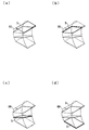
- FIG. 9 is a plan view, a front view, a perspective view, and an explanatory diagram for explaining changes in the angle and position of the substrate reversing unit in the reversing process, showing the reversing mechanism shown in FIG. 8.
- FIG. 9 is an explanatory diagram for explaining a change in the angle of the intermediate rotating member and a change in the position of the substrate reversing portion disposed on the outer peripheral wall of the intermediate rotating member in the circumferential direction in the reversing process of the reversing mechanism shown in FIG. 8. .
- It is a top view which shows the modification of the bonding apparatus which concerns on a present Example.
- the manufacturing system includes a bonding apparatus according to the present invention.
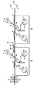
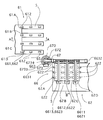
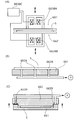
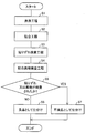
- FIG. 1 is a cross-sectional view showing a manufacturing system.
- the manufacturing system 100 has a two-stage structure, a 1F (first floor) portion is a film transport mechanism 50, and a 2F (second floor) portion is a bonding apparatus 60 including a substrate transport mechanism. It has become.
- the film transport mechanism 50 plays the role of unwinding the polarizing film (polarizing plate) and transporting it to the nip rolls 6 ⁇ 6a and 16 ⁇ 16a and winding up the peeling film that is no longer needed.
- the bonding device 60 plays a role of bonding the polarizing film unwound by the film transport mechanism 50 to the substrate (liquid crystal panel) 5.
- the film transport mechanism 50 includes a first film transport mechanism 51 and a second film transport mechanism 52.
- the 1st film conveyance mechanism 51 conveys a polarizing film to the nip roll 6 * 6a which bonds a polarizing film to the lower surface of the board
- the second film transport mechanism 52 transports the polarizing film to the bottom surface of the inverted substrate 5.
- the first film transport mechanism 51 includes a first unwinding unit 1, a second unwinding unit 1a, a first winding unit 2, a second winding unit 2a, a half cutter 3, a knife edge 4, and a defect film winding roller. 7 ⁇ 7a.
- the first unwinding unit 1 is provided with a polarizing film original, and the polarizing film is unwound.
- a known polarizing film may be used as the polarizing film. Specifically, a polyvinyl alcohol film is dyed with iodine or the like, and a film stretched in a uniaxial direction can be used. Although it does not specifically limit as thickness of the said polarizing film, A polarizing film 5 micrometers or more and 400 micrometers or less can be used preferably.
- the polarizing film has a pressure-sensitive adhesive layer protected by a release film.
- a release film also referred to as a protective film or a separator
- a polyester film, a polyethylene terephthalate film, or the like can be used.
- the peeling film of 5 micrometers or more and 100 micrometers or less can be used preferably.
- the manufacturing system 100 includes two unwinding portions and two unwinding portions corresponding to the unwinding portions, the first unwinding portion 1 has a low remaining amount of raw material. It is possible to connect the original fabric provided in the two unwinding portions 1 a to the original fabric of the first unwinding portion 1. As a result, it is possible to continue the operation without stopping the unwinding of the polarizing film. With this configuration, production efficiency can be increased.
- a plurality of unwinding sections and winding sections may be provided, and three or more winding sections may be provided.
- Half cutter (cutting unit) 3 half-cuts a polarizing film (a film laminate composed of a polarizing film, a pressure-sensitive adhesive layer and a peeling film) protected by a peeling film, and cuts the polarizing film and the pressure-sensitive adhesive layer.
- a polarizing film a film laminate composed of a polarizing film, a pressure-sensitive adhesive layer and a peeling film
- the half cutter 3 a known member may be used. Specifically, a cutter, a laser cutter, etc. can be mentioned. After the polarizing film and the pressure-sensitive adhesive layer are cut by the half cutter 3, the release film is removed from the polarizing film by the knife edge (removal part) 4.
- the pressure-sensitive adhesive layer is not particularly limited, and examples thereof include acrylic, epoxy, and polyurethane pressure-sensitive adhesive layers.
- the thickness of the pressure-sensitive adhesive layer is not particularly limited, but is usually 5 to 40 ⁇ m.
- the 2nd film conveyance mechanism 52 is the structure similar to the 1st film conveyance mechanism 51, and is the 1st unwinding part 11, the 2nd unwinding part 11a, the 1st winding part 12, and the 2nd winding part 12a. , Half cutter 13, knife edge 14 and defect film winding rollers 17 and 17 a. About the member which attached
- the manufacturing system 100 includes a cleaning unit 71.
- the cleaning unit 71 cleans the substrate 5 before the polarizing film is bonded to the lower surface of the substrate 5 by the nip rolls 6 and 6a.
- a known cleaning unit composed of a nozzle and a brush for injecting a cleaning liquid may be used. By cleaning the substrate 5 immediately before the bonding by the cleaning unit 71, the bonding can be performed in a state where there are few adhered foreign substances on the substrate 5.
- FIG. 2 is a cross-sectional view showing a peripheral portion of the nip rolls 6 and 6a in the manufacturing system 100.
- FIG. FIG. 2 shows a situation where the substrate 5 is conveyed from the left direction and the polarizing film 5a having an adhesive layer (not shown, the same hereinafter) is conveyed from the lower left direction.
- the polarizing film 5a is provided with a release film 5b.
- the polarizing film 5a and the pressure-sensitive adhesive layer are cut by the half cutter 3, and the release film 5b is not cut (half cut).
- the knife edge 4 is installed on the peeling film 5b side.
- the knife edge 4 is an edge-shaped member for peeling the peeling film 5b, and the polarizing film 5a and the peeling film 5b having a low adhesive force are peeled off along the knife edge 4.
- the release film 5b is wound around the first winding portion 2 in FIG.
- it can replace with a knife edge and can also use the structure which winds up a peeling film using an adhesion roller.
- the winding efficiency of a peeling film can be improved by providing an adhesive roller in two places similarly to a winding part.
- the bonding apparatus 60 conveys the board
- the bonding apparatus 60 is provided on the upper part of the film transport mechanism 50. Thereby, space saving of the manufacturing system 100 can be achieved.
- a substrate transport mechanism including a conveyor roll is installed in the bonding device 60, whereby the substrate 5 is transported in the transport direction (the first substrate transport device 61 and the second substrate described later in FIG. 6).
- the substrate transfer device 62 corresponds to a substrate transfer mechanism).
- the substrate 5 is transported from the left side, and then transported from the right side in the drawing, that is, from the top of the first film transport mechanism 51 to the top of the second film transport mechanism 52.
- the substrate 5 has a rectangular shape, and the ratio of the long side and the short side is not particularly limited, but may be, for example, a ratio of 16: 9 to 4: 3.
- substrate 5 the glass substrate panel of an organic electroluminescent panel and a liquid crystal cell can be mentioned, for example.
- the nip roll (1st bonding part) 6 * 6a and the nip roll (2nd bonding part) 16 * 16a which are bonding parts are each provided.
- the nip rolls 6, 6 a and 16, 16 a are members that serve to bond a polarizing film from which the release film has been removed to the lower surface of the substrate 5.
- the substrate 5 is reversed by the reversing mechanism 65 after being bonded by the nip rolls 6 and 6a.
- the reversing mechanism 65 will be described later.
- the polarizing film conveyed to the nip rolls 6 and 6a is bonded to the lower surface of the substrate 5 through an adhesive layer.
- known configurations such as a pressure roll and a pressure roll can be employed.
- what is necessary is just to adjust the pressure and temperature at the time of bonding in the nip rolls 6 and 6a suitably.
- the configuration of the nip rolls 16 and 16a is the same.
- a defect display (mark) detection unit is provided between the first unwinding unit 1 and the half cutter, and a polarizing film having a defect is detected. It has a configuration.
- the said defect display is provided at the time of the 1st unwinding part 11 or the 2nd unwinding part 11a rather than a defect display detection part by performing the detection at the time of original film production of a polarizing film, and providing a defect display. It attaches
- the defect display imparting unit includes a camera, an image processing device, and a defect display forming unit. First, a polarizing film is imaged by the camera, and the presence or absence of a defect can be inspected by processing the imaging information. Specific examples of the drawback include foreign matters such as dust and fish eyes. When a defect is detected, a defect display is formed on the polarizing film by the defect display forming unit. A mark such as ink is used as the defect display.
- a bonding avoiding unit discriminates the mark with a camera and transmits a stop signal to the bonding apparatus 60 to stop the conveyance of the substrate 5. Thereafter, the polarizing film in which the defect is detected is not bonded by the nip rolls 6 and 6a and is wound by the defect film winding roller (collecting unit) 7 and 7a. Thereby, pasting with substrate 5 and a polarizing film which has a fault can be avoided. If the said series of structures are provided, since the bonding with the polarizing film which has a fault, and the board
- a publicly known inspection sensor can be used suitably as a fault detection part and a pasting avoidance part.
- the substrate 5 is conveyed to the nip rolls 16 and 16a. Then, a polarizing film is bonded to the lower surface of the substrate 5. As a result, the polarizing film is bonded to both surfaces of the substrate 5, and the two polarizing films are bonded to both surfaces of the substrate 5 with different absorption axes. Thereafter, if necessary, the both sides of the substrate 5 are inspected for misalignment.
- the inspection can be usually performed by an inspection unit equipped with a camera.
- the bonding is performed from the lower surface of the substrate 5, and the rectifying environment to the substrate 5 is not hindered. For this reason, foreign matter mixing into the bonding surface of the substrate 5 can also be prevented, and more accurate bonding is possible.
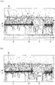
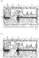
- FIG. 3 (a) and FIG. 3 (b) show the velocity vector of the airflow in the under-paste type manufacturing system similar to the present invention.
- Regions A in FIGS. 3 (a) and 3 (b) are regions where the unwinding part is installed
- region B is a region through which the polarizing film mainly passes
- region C is a region where the winding unit and the like are installed. It is. Further, clean air is supplied from the HEPA filter 40.
- FIG. 3A since the grating 41 through which clean air can pass is installed, the airflow can move in the vertical direction via the grating 41.
- FIG. 3B since the grating 41 is not installed, the airflow moves along the floor after contacting the floor.
- FIGS. 3 (a) and 3 (b) Since the manufacturing system shown in FIGS. 3 (a) and 3 (b) is a bottom-attached type, the air current from the HEPA filter 40 is not hindered by the polarizing film as shown in FIGS. 10 (a) and 10 (b). For this reason, the direction of the airflow vector is almost directed toward the substrate, and it can be said that a preferable rectification environment is realized in the clean room.
- the grating 41 is installed and not installed in FIG. 3 (b), but both drawings show the same preferable state. 3 and 10
- the substrate transport mechanism is formed horizontally, but is not installed as a series of structures. For this reason, the airflow can pass between the substrate transport mechanisms. After the substrate is held by a reversing mechanism to be described later, the substrate is transferred between the substrate transport mechanisms.
- substrate 5 is first conveyed by a long side opening (a long side is orthogonal to a conveyance direction), and is conveyed by a short side opening (a short side is orthogonal to a conveyance direction) after that. It has become.
- the substrate support device that holds the substrate 5 transported by the first substrate transport mechanism 61 when the substrate 5 is reversed is mechanically sandwiched by a plurality of substrate support members or is suctioned by utilizing a suction action of fluid pressure. Other embodiments are possible.
- the suction unit 66 ⁇ / b> S is configured by a plurality of suction members having a plurality of suction ports opened to suck a plurality of locations on the surface of the substrate 5 transported by the first substrate transport mechanism 61. As a result, the surface of the substrate 5 is held by the suction portion 66.
- the adsorption unit 66 a known adsorption unit can be used, and for example, an air suction type adsorption unit can be used.
- the substrate support device 66 is of a type that is mechanically sandwiched as shown in FIGS. 5 to 7, and has a downstream end portion in the film and substrate transport direction of the first substrate transport mechanism 61 including the conveyor roll 612. And the upstream end of the second substrate transport mechanism 61 including the conveyor roll 622 in the transport direction of the film and the substrate so as not to interfere even if the backlash is taken into consideration, and the substrate reversing portion 67 of the reversing mechanism 65
- the present invention relates to a substrate support device in a substrate transport mechanism configured such that first and second substrate support portions 661 and 662 are interposed in accordance with the reversing operation.
- the substrate support device 66 is configured by a pair of comb-shaped members having a size larger than that of the substrate on which the film is bonded, and the two pairs of comb-shaped members are connected to the substrate reversing unit 67.
- the base member 660 is disposed so as to be able to swing relative to the base member 660.
- two substrate support devices 66 are arranged at an angle of 180 degrees on the vertical plane from the viewpoint of shortening the tact time, and the substrate support devices 66 are transported by the first and second substrate transport mechanisms 61 and 62. And a first substrate extending in the width direction of the first substrate transport mechanism 61 and connected to the two substrate reversing portions 67 of the reversing mechanism disposed at an intermediate position between the direction and the width direction orthogonal to the transport direction. It is also possible for the substrate support device 66 and the second substrate support device 66 extending in the transport direction of the second substrate transport mechanism 62 to be arranged so as to be orthogonal to each other in the same plane. Further, in order to shorten the tact time, it is possible to arrange four (six) substrate support devices with respect to the substrate reversing portion 67 at an angular relationship of 90 degrees (60 degrees) on the vertical plane.
- one substrate support device 66 is disposed so as to face the downstream end in the film and substrate transport direction of the first substrate transport mechanism 61 including the conveyor roll 612 as shown in FIG.
- the other substrate support device 66 is configured to be inserted into and disposed at the upstream end portion of the film and substrate transport direction of the second substrate transport mechanism 62 including the conveyor roll 622.
- the substrate support device 66 is disposed on a member connected to the substrate reversing unit 67 that performs the reversing operation of the substrate, and transports a rectangular substrate with a long side or a short side along a transport direction.
- the substrate 5 transported from the first substrate transport mechanism between the first support member 661 and the second support member 662 is supported by being sandwiched between the first support member 661 and the second support member 662.
- the first support member 661 and the second support member 662 are sandwiched between the first support member 661 and the second support member 662 reversed by the substrate reversing unit 67 by the relative movement of the first support member 661 and the second support member 662.
- the substrate reversing unit 67 by the relative movement of the first support member 661 and the second support member 662.
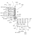
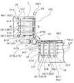
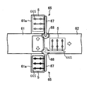
- the downstream end of the first substrate transport mechanism 61 is divided into a plurality of, for example, four divided portions 61A, 61B, 61C, 61D in the width direction, and the first and second divided portions are adjacent to each other.
- a plurality of gaps are formed through which a plurality of, for example, three projecting portions 6611 to 6613 and 6621 to 6623 of the first and second comb-shaped members of the substantially E shape constituting the support members 661 and 662 enter.
- the upstream end portion of the second substrate transport mechanism 62 is divided into a plurality of, for example, four divided portions 62A, 62B, 62C, and 62D in the transport direction, and the first and second portions inverted between adjacent divided portions.
- a plurality of gaps into which the plurality of protrusions 6611 to 6613 and 6621 to 6623 of the first and second comb-like members constituting the second support members 661 and 662 enter are formed.
- the four divided portions 61A, 61B, 61C, and 61D divided in the width direction have transport rollers 612 respectively.
- the substrate 5 which is disposed and rotated in synchronism via a rotation drive mechanism and a rotation communication means (not shown) in accordance with a rotation drive command and the deflection film is bonded to the lower surface is conveyed to the right in the drawing.
- the stop position When the stop position is reached, it is configured to stop.
- the second substrate transport mechanism 62 As shown in FIGS. 5 and 6, at the upstream end of the second substrate transport mechanism 62, four divided portions 62A, 62B, 62C, 62D divided in the substrate transport direction are respectively provided with transport rollers. 622 is disposed, is rotated in synchronization with a rotation drive mechanism and a rotation communication means (not shown) in accordance with a rotation drive command, is reversed by the substrate reversing unit 67, and the deflection film is bonded to the upper surface. It is comprised so that the board
- substrate 5 may be conveyed by the 2nd bonding apparatus of the right side in a figure.
- the first and second support members 661 and 662 are first and second comb-like members each having a plurality of protrusions 6611 to 6613 and 6621 to 6623.
- the base member 660 is controlled by a swing member that swings around one end of the base portion 660 as a fulcrum.
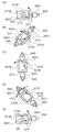
- the first and second comb-like members having the plurality of projecting portions 6611 to 6613 and 6621 to 6623 constituting the first and second support members 661 and 662 are fixed at a predetermined angle by the swing drive mechanism 6630. It is configured to be driven to swing within a range, for example, a range of 90 degrees.
- the swing drive mechanism 6630 swings and drives the first comb-like member provided with a plurality of protrusions 6611 to 6613 constituting the first support member 661 in FIG.
- the second comb-shaped member having the upper first swing driving mechanism 6631 and the plurality of protrusions 6621 to 6623 constituting the second support member 662 is driven to swing in the lower part of FIG. 2 oscillating drive mechanisms 6632.
- the first swing drive mechanism 6631 is an electric drive disposed at one end of a base member 660 that is connected to an end 672 of the substrate reversing portion 67 that performs the reversing operation of the substrate via the connecting portion 673.
- the intermediate hollow shaft 6601 is constituted by a first motor as a device, and the intermediate hollow shaft 6601 is inserted into the base member 660 in accordance with a driving force and a swing direction based on a swing command.
- the plurality of projecting portions 6611 to 6613 constituting the first comb-like member as the first support member 661 connected integrally are configured to swing and rotate.
- FIGS. 5 to 10 four divided portions 61 ⁇ / b> A at the downstream end of the first substrate transport mechanism 61 are arranged via a rotation drive mechanism and a rotation communication means (not shown) in accordance with a rotation drive command.
- the transport roller 612 is rotationally driven, and the substrate 5 with the deflection film bonded to the lower surface is transported to the right in the figure, and when it reaches the stop position and stops, the first swinging is performed.
- the first motor as an electric drive device constituting the dynamic drive mechanism 6631 swings the intermediate hollow shaft 6601 inserted in the base member 660 in the counterclockwise direction according to the drive force and the swing direction based on the swing command. As shown in FIG.
- the plurality of protrusions 6611-6 in the vertical state as shown in FIG. 9 is rotated by 90 degrees counterclockwise, as shown in FIG. 9B, between the plurality of protrusions 6621 to 6623 constituting the second comb-shaped member in the horizontal state. Further, the substrate 5 having the deflection film bonded to the lower surface that is stopped is sandwiched and supported.
- the second swing drive mechanism 6632 is an electrical element disposed at the other end of the base member 660 connected to the end 672 of the substrate reversing portion 67 for performing the reversing operation of the substrate via the connecting portion 673.
- the second motor as a driving device is configured to be integrally connected to the central shaft by swinging and rotating the central shaft 6602 inserted in the base member 660 according to the driving force and the swinging direction.
- the plurality of protrusions 6621 to 6623 constituting the second comb-like member as the second support member 662 are configured to swing and rotate.
- the substrate reversing portion 67 of the substrate reversing mechanism described later is reversed around the reversing axis. Therefore, as shown in FIG.
- a second motor as an electric drive device constituting the second swing drive mechanism 6632 moves the center shaft 6602 inserted in the base member 660 against the center shaft 6602 according to the drive force and the swing direction based on the swing command.
- the plurality of protrusions in a horizontal state as shown in FIG. 10 (A) constituting the second comb-shaped member integrally connected to the central shaft 6602 by swinging and rotating clockwise.
- the swing drive mechanism 6630 constitutes one motor 6630 as a swing drive source and the swing support force from the motor 6630 constitutes the first support member 661.
- the first clutch means 6633 that rotates and communicates with the first comb-like member having a plurality of protruding portions 6611 to 6613, and the oscillation from one motor 6630 as the oscillation drive source.
- the driving force is composed of a second clutch means 6634 that rotates and communicates with the second comb-like member provided with a plurality of protrusions 6621 to 6623 constituting the second support member 662. Since the single motor 6630 as the swing drive source is provided, the substrate support device is suitable for simplification and weight reduction.
- the swing drive mechanism 6630 uses actuators 6635 and 6636 as the first and second swing drive sources, and the swing drive mechanism 6630 uses a swing member that swings about a fulcrum.
- the first and second support members 661 and 662 are formed.
- the plurality of protrusions 6611 to 6613 and 6621 to 6623 of the comb-like member are swung around a fixed angle range, for example, about 0 to ⁇ 30 degrees, respectively, so that the substrate 5 is sandwiched and supported.
- a mode that enables the release of the support state is possible, and the controller 6637 controls the application of current to the solenoids that constitute the actuators 6635 and 6636. Since is realized by-off control, it has the advantage that control is simple.
- first and second support members 661 and 662 have been described.
- the embodiment is described with reference to the first and second embodiments.
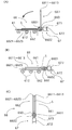
- the first and second comb-like members having a plurality of projecting portions constituting the supporting member are configured to be reciprocable so that the opposing distance changes by relatively approaching or separating in the vertical direction. Is possible.
- first and second comb-like members having a plurality of protrusions 6611 to 6613 and 6621 to 6623 constituting the first and second support members 661 and 662 are linear drive mechanisms, that is, reciprocating drive. It can be configured to be driven and reciprocated by a mechanism.
- the linear drive mechanism is driven by the drive force in the vertical direction in FIG. 12 of the first and second solenoids 6638A, 6638B and other electrical drive devices according to the drive current from the controller 6638C.
- At least one of the first and second support members 661 and 662 approaches relatively, thereby sandwiching and supporting the substrate 5, and after reversing, at the upstream end of the second substrate transport mechanism It is also possible to configure such that the sandwiched state of the substrate 5 is released by relatively separating at least one of the first and second support members 661 and 662.
- the linear drive mechanism has an adsorbing portion 6639 that adsorbs the substrate 5 to the contact surfaces of the plurality of protruding portions of the comb-like member constituting the substrate supporting member 661 with the substrate 5.
- the substrate 5 is adsorbed or sandwiched by a negative pressure suction action by a fluid pressure supplied from a pump P as a driving device, so that the first and second comb-shaped members are relative to each other. It is possible to configure the substrate to be sandwiched and supported by approaching to the substrate. If a pump or a pressure source as a driving device is installed at an appropriate place in the factory and communicated with the pipe, There is an advantage that the structure of the support device can be simplified, and the weight can be reduced and the speed can be increased.
- a plurality of sucked portions and sucked portions 6639 are formed at both ends of the first and second support members 661 and 662, and a suction pump P such as a vacuum pump as a driving device is formed.
- the suctioned part is adsorbed by the adsorbing part 6639 by the negative pressure suction action by the fluid pressure (negative pressure) supplied from the pipe through the pipe, thereby moving the first support member 661 upward in the figure.
- the substrate can be sandwiched and supported between the first and second support members 661 and 662, and a pump or a pressure source as a driving device is installed at an appropriate place in the factory.
- the configuration of the substrate supporting device can be simplified, and the weight can be reduced and the speed can be increased.
- the said embodiment demonstrated the aspect which adsorb
- substrate support apparatus in the bonding apparatus of a polarizing film is the said 1st board
- a polarizing film laminating apparatus including a substrate supporting device 66 having a substrate supporting portion for supporting the substrate, the first substrate is disposed on a base member 660 connected to a substrate reversing portion 67 that performs a reversing operation of the substrate.
- the transport mechanism 61 and the first Due to the relative movement of the first support member 661 and the second support member 662 entering the end portion of the substrate transport mechanism 62, the first support member 661 and the second support member 662 are moved to the first support member 662.
- the substrate 5 to which the first polarizing film transported from the one substrate transport mechanism 61 is bonded is supported by being sandwiched, and the first support member 661 and the second support member 662 are supported.
- the first polarizing film supported by being sandwiched between the first support member 661 and the second support member 662 reversed by the substrate reversing unit 67 by the relative movement of the substrate is bonded.
- the above-described substrate 5 is configured such that the support by the clamping is released and the substrate 5 is placed on the end portion of the second substrate transport mechanism 62.
- the substrate support mechanism in the polarizing film laminating apparatus includes a first substrate transport mechanism 61 that transports a rectangular substrate in a state where the long side or the short side is along the transport direction, and the substrate in the first substrate transport mechanism.
- the 1st bonding part 6 which bonds the 1st polarizing film to the lower surface of 2nd
- the 2nd substrate conveyance mechanism 62 which conveys the above-mentioned substrate in the state where the short side or the long side followed the conveyance direction
- the substrate supported by the substrate supporting unit is reversed, and the arrangement is changed and arranged in the second substrate transport mechanism.
- Including reversing mechanism In the optical film laminating apparatus, it is disposed on the base member 660 connected to the substrate reversing portion 67 of the reversing mechanism that performs the reversing operation of the substrate, and ends of the first substrate transport mechanism 61 and the second substrate transport mechanism 62. From the first substrate transport mechanism 61 between the first support member 661 and the second support member 662 due to the relative movement of the first support member 661 and the second support member 662 entering the portion.
- the substrate 5 on which the conveyed first polarizing film is bonded is supported by being sandwiched, and by the relative movement between the first support member 661 and the second support member 662, The substrate 5 on which the first polarizing film supported by being sandwiched between the first support member 661 and the second support member 662 reversed by the substrate reversing unit 67 is bonded. Support by the clamping is released, and is adapted to be mounted on an end portion of the second substrate transport mechanisms.
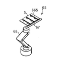
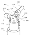
- the reversing mechanism is a reversing mechanism disposed at an intermediate position in the width direction of the first and second substrate transport mechanisms 61 and 62 orthogonal to the transport direction of the substrate.
- a substrate reversing unit 67 is provided which is rotatably arranged on the base unit 670 and realizes a reversing operation.
- substrate support part is a member which supports the board
- the substrate support part includes an adsorbing means for adsorbing the substrate 5 as a preferred form.
- an adsorption means for example, an air suction type adsorption means can be used.
- the substrate support part is composed of a pipe-shaped arm and suction means, and the air sucked by the suction means passes through the arm, but the shape of the arm and suction means is limited to this configuration. It is not something.
- the substrate support portion has a structure in which two adsorption means are provided on the arm, and includes a pair of arm groups including three arms. Further, four suction means are arranged on the diagonal line of the substrate 5, and two further suction means are arranged between the suction means in the length direction of the substrate 5.
- the number of arms and the number of suction means are merely examples. For example, when a large substrate is reversed, the number of arms and the number of suction means may be increased as appropriate. Further, it is of course possible to make changes such as concentrating the installation location of the suction means on the central portion of the substrate 5 or changing it around the edge of the substrate 5.
- the distance between the arm groups is increased so that the substrate 5 can be received (hereinafter, this state is referred to as “standby state”).
- the distance between the arm groups of the substrate 5 is also increased.
- the pair of arm groups sandwich the substrate 5, the distance between the arm groups can be reduced.
- the distance between the arm groups can be changed.
- the substrate support section has a motor, and the rotational movement of the motor is changed to a linear movement to change the distance between the arm groups. Yes.
- it is the structure which can change the distance between arm groups you may change and use for the structure provided with a motor.
- the substrate support device 66 is disposed on the base member 660 connected to the substrate reversing unit 67 for performing the reversing operation of the substrate, and the rectangular substrate is long. Ends of the first substrate transport mechanism 61 that transports the side or short side along the transport direction and the second substrate transport mechanism 62 that transports the substrate along the short side or long side along the transport direction From the first substrate transport mechanism 61 between the first support member 661 and the second support member 662 due to the relative movement of the first support member 661 and the second support member 662 entering the portion.
- the transported substrate 5 is supported by being sandwiched, and is reversed by the substrate reversing unit 67 by the relative movement of the first support member 661 and the second support member 662.
- First The substrate 5 supported by being sandwiched between the support member 661 and the second support member 662 is released from the support, and placed on the end of the second substrate transport mechanism 62. Therefore, with a simple configuration, the substrate 5 transported by the first substrate transport mechanism 61 enters the first support member 661 and the first support member 661 that have entered the end of the first substrate transport mechanism 61.
- the substrate reversing unit 67 can invert the substrate, and the substrate reversing unit 67 can invert the substrate.
- the substrate supported by being sandwiched between the first support member 661 and the second support member 662 thus released is released from the support, and the second substrate transport mechanism 6 is released.
- the effect of allowing bonding of the transfer and polarizing film of the substrate in the second substrate transport mechanism 62 is released.
- the polarizing film laminating apparatus of the present embodiment includes a plurality of cross-section portions 61 ⁇ / b> A, 61 ⁇ / b> B, 61 ⁇ / b> C, 61 ⁇ / b> D formed in the width direction at the end of the first substrate transport mechanism 61.
- the plurality of protrusions 6611 to 6613 and 6621 to 6623 of the first and second comb-like members constituting the first and second support members 661 and 662 enter the gap, the first and second support members 661 and 662 enter the gap.
- the substrate 5 transported from the first substrate transport mechanism 61 is securely supported by being sandwiched between the plurality of protrusions of the second comb-shaped member.
- the first and second support members 6 are inverted in a plurality of gaps formed between adjacent portions of the plurality of divided portions 62A, 62B, 62C, 62D in the transport direction at the end of the two-substrate transport mechanism 62.
- the plurality of protrusions 6611 to 6613 and 6621 to 6623 of the first and second comb-shaped members constituting the first and second components 662 enter, the support by the sandwiching of the inverted substrate is released, and the second substrate transport By being placed on the end portion of the mechanism 62, the substrate can be transported and the deflection film can be bonded in the second substrate transport mechanism 62.
- the polarizing film laminating apparatus of the present embodiment is arranged such that the first and second gaps are formed between adjacent portions of the plurality of divided portions in the width direction at the end of the first substrate transport mechanism 61.
- the plurality of protrusions of the first and second comb-like members constituting the second support members 661 and 662 enter, and the plurality of protrusions 6611 ⁇ of at least one of the first and second comb-like members enters.
- 6613 and 6621 to 6623 swing around a certain range with a part as a fulcrum, so that the substrate 5 transported from the first substrate transport mechanism 61 is replaced with a plurality of the first and second comb-shaped members.
- a plurality of protrusions of the first and second comb-shaped members constituting the inverted first and second support members 661 and 662 enter the gap, and at least one of the first and second combs enters.
- the plurality of protrusions of the member are swung in a certain angle range with a part as a fulcrum, thereby releasing the support by sandwiching the inverted substrate and placing it on the end of the second substrate transport mechanism 62 As a result, the substrate is transported and the deflection film is bonded in the second substrate transport mechanism 62.
- the polarizing film laminating apparatus of the present embodiment includes the first and second combs provided with a plurality of protrusions 6611 to 6613 and 6621 to 6623 constituting the first and second support members 661 and 662.
- the substrate-like member is driven to swing by the swing drive mechanism, the substrate 5 transported from the first substrate transport mechanism 61 is moved into the plurality of protrusions 6611 of the first and second comb-like members.
- the second substrate transport mechanism 62 can transport the substrate 5 and bond the deflection film.
- the first swing drive mechanism 6631 constituting the swing drive mechanism has a plurality of protrusions 6611 to 6613 constituting the first support member 661, and the like.
- the first comb-like member having 6621 to 6623 is driven to swing, and the second swing drive mechanism 6632 constituting the swing drive mechanism has a plurality of protrusions constituting the second support member 662.
- the substrate 5 transported from the first substrate transport mechanism 61 is driven by swinging the second comb-shaped member provided with a portion so that the plurality of protrusions of the first and second comb-shaped members 6611 to 6613 and 6621 to 6623 are securely supported by being sandwiched, and the support by the sandwiching of the inverted substrate is released, and the end of the second substrate transport mechanism 62 is released.
- the swing drive mechanism is configured such that the swing drive source 6630 and the swing drive force from the swing drive source are transmitted through the first clutch means 6633.
- the first driving member 661 is provided with a plurality of projecting portions 6611 to 6613, and is transmitted to the first comb-like member for swinging driving.
- the swinging driving force from the swinging drive source 6630 is transferred to the first comb member.
- the substrate 5 transported from the mechanism 61 has an effect that it is reliably supported by being sandwiched between the plurality of protrusions of the first and second comb-shaped members, and is inverted. Clamping the substrate 5 The effect of enabling the transfer of the substrate 5 and the bonding of the deflection film in the second substrate transfer mechanism 62 by being released from the support and placed on the end of the second substrate transfer mechanism 62. Play.
- the polarizing film laminating apparatus of the present embodiment has a plurality of portions formed between adjacent portions of the plurality of divided portions 61A, 61B, 61C, 61D in the width direction at the end of the first substrate transport mechanism 61.
- a plurality of projecting portions 6611 to 6613 and 6621 to 6623 of the first and second comb-like members constituting the first and second support members 661 and 662 enter the gap, and at least one of the first When the plurality of protrusions of the second comb-shaped member relatively approach in the vertical direction, the substrate 5 transported from the first substrate transport mechanism 61 becomes the first and second comb-shaped members.
- the plurality of divided portions 62A and 62B in the transport direction at the end of the second substrate transport mechanism 62 are obtained.
- the second substrate transport mechanism 62 can transport the substrate 5 and bond the deflection film. .
- the deflection film laminating apparatus of the present embodiment is provided with a plurality of protrusions 6611 to 6613 and 6621 to 6623 constituting the first and second support members 661 and 662 by the linear drive mechanisms 6638A and 6638.
- the first and second comb-shaped members provided are linearly driven and reciprocated, whereby the substrate 5 transported from the first substrate transport mechanism 61 is moved to the first and second comb-shaped members.
- the support by the sandwiching of the inverted substrate 5 is released, and the end of the second substrate transport mechanism 62 is released.
- the second substrate transport mechanism 62 has an effect of enabling the transport deflection film of the substrate 5 to be bonded.
- the linear drive mechanism is a comb-like member that constitutes the first and second support members 661 and 662 by the drive force of the electrical drive devices 6638A and 6638. Since the substrate 5 is sandwiched and supported by relatively approaching, the control for sandwiching and supporting the substrate by the driving force of the electric drive device based on the drive command is easy. It has the effect of realizing.
- the linear driving mechanism is adsorbed or sandwiched by the action of fluid pressure supplied from the driving apparatus, whereby the first and second support members 661 described above are used. , 662 are relatively close to each other so that the substrate 5 is sandwiched and supported. Therefore, a driving device for supplying fluid pressure is arranged separately from the substrate support member. As a result, the structure of the substrate support member can be simplified and the weight can be reduced.
- the deflection film laminating apparatus of this example is disposed on the base member 660 connected to the substrate reversing unit 67 that performs the reversing operation of the substrate, and the long side or the short side of the rectangular substrate is along the transport direction.
- the first substrate transport mechanism 61 that transports the substrate in a state and the first support member 661 that enters the end of the second substrate transport mechanism 62 that transports the substrate with the short side or the long side along the transport direction.
- the first polarizing film transported from the first substrate transport mechanism 61 is pasted between the first support member 661 and the second support member 662 by relative movement between the first support member 662 and the second support member 662.
- the combined substrate 5 is securely supported by being sandwiched, and the substrate reversing portion 67 is obtained by the relative movement of the first support member 661 and the second support member 662.
- the substrate 5 on which the first polarizing film supported by being sandwiched between the inverted first support member 661 and the second support member 662 is bonded is supported by sandwiching. Since it is released and placed on the end of the second substrate transport mechanism 62, the substrate on which the first polarizing film is bonded by the substrate reversing unit 67 connected to the base member 660.
- the reversing operation of the substrate reversing unit 67 to the end of the second substrate transport mechanism 62 that transports the substrate with the short side or the long side along the transport direction, and the second bonding unit 16 performs the second reversal operation There exists an effect of enabling bonding of a polarizing film.
- the polarizing film laminating apparatus of the present embodiment is arranged such that the substrate support device is disposed on the base member 660 connected to the substrate reversing portion 67 of the reversing mechanism that performs the reversing operation of the substrate, and the first substrate transport
- the first support member 661 and the second support member 662 are moved relative to each other by the relative movement of the first support member 661 and the second support member 662 entering the end portions of the mechanism 61 and the second substrate transport mechanism 62. Since the said board
- the first support member 661 reversed by the substrate reversing portion 67 by the relative movement of the first support member and the second support member is obtained while the substrate 5 is reliably supported.
- second The substrate 5 on which the first polarizing film supported by being sandwiched between the support member 662 is bonded is released from the support, and the end of the second substrate transport mechanism 62 is released. Since the substrate 5 is bonded to the base member 660, the substrate 5 on which the first polarizing film is bonded is placed on the substrate with the short side or the long side along the transport direction.
- the substrate reversing unit 67 can be reversed to the end of the second substrate transporting mechanism 62 that is transported at the end, and the second polarizing film can be bonded to the second bonding unit 16.
- the reversing mechanism 65 is a member that reverses the substrate 5 transported by the first substrate transport mechanism and places it on the second substrate transport mechanism.
- the first substrate transport mechanism and the second substrate transport mechanism are arranged in the same direction.
- FIG. 4 is a perspective view showing the reversing mechanism 65.
- the reversing mechanism 65 includes a first substrate reversing unit (substrate reversing unit) 67 and a second substrate reversing unit (substrate reversing unit) 68.
- the first substrate reversing portion 67 has a rod shape and includes a suction portion 66.
- the first substrate reversing unit 67 can rotate in its own axial direction, and can move the substrate 5 in a direction perpendicular to the axis via the adsorption unit 66.
- the first substrate reversing unit 67 is connected to the second substrate reversing unit 68.
- the connecting portion can be driven, and the position of the first substrate reversing unit 67 can be changed, and the position of the substrate 5 can be changed.
- the second substrate reversing part 68 has a structure in which the base part can be rotated horizontally.
- the substrate 5 can be moved in the vertical direction by the two arm structures, and the substrate 5 can be rotated in the horizontal direction by the rotation of the base portion.
- the structure of the first substrate reversing unit 67 and the second substrate reversing unit 68 is shown as the substrate reversing unit, but the substrate reversing unit is not limited to this configuration.
- a robot arm having a control unit can be used as a preferred form. When a robot arm is used, it is preferable because a more precise operation of the substrate 5 is possible.
- a known robot arm can be used as the robot arm.
- FIG. 13 is a perspective view showing a trajectory when the substrate 5 is reversed.
- FIG. 13A corresponds to the state of the substrate 5 in FIG.
- the suction unit 66, the first substrate reversing unit 67, and the second substrate reversing unit 68 are not shown so that the trajectory of the substrate 5 can be easily grasped.
- the substrate 5 is transferred from the first substrate transfer mechanism with the short side of the substrate 5 along the transfer direction.
- the substrate 5 stops before the first substrate reversing unit 67 (not shown), and the adsorption unit 66 is adsorbed on the surface of the substrate 5.
- the substrate 5 has the second substrate transport mechanism such that the short side along the transport direction of the first substrate transport mechanism is along the direction orthogonal to the transport direction. Placed in.
- the first substrate reversing unit 67 and the second substrate reversing unit 68 are configured so that the substrate 5 draws a curve so as to change the state of the substrate 5 in FIG. 13A to the state of the substrate 5 in FIG. Move. That is, the substrate 5 is moved by a gentle 1 operation. Therefore, the reversal of the substrate 5 in the present embodiment does not involve a linear movement, for example, a reversal movement in a direction along one side of the substrate 5. Further, this operation is not an operation in which the two operations of reversing the substrate and turning in the horizontal direction of the substrate are continued, and these two operations are not performed simultaneously.
- the substrate 5 in FIG. 13A has one short side (on the left side in the figure) as the inside and the other (right side in the figure) the short side as the outside.
- the rotation drive system of each axis of the ropot shown in FIG. 4 is turned off, and each axis of the robot can be moved by the operator, and the angle and displacement of each axis of the moved robot.
- the posture of the substrate 5 and the angle and displacement of each axis of the robot that realizes the posture are taught and stored by the operator as described below.
- the substrate 5 is lifted from the horizontal plane where the substrate 5 is located, and the substrate 5 is moved in an inclined state so that the outer short side is higher than the inner short side. .
- the substrate 5 ′ indicates the position after the substrate 5 has moved.
- a curve 69 indicates the locus of the substrate 5 connecting the corresponding vertices in the substrate 5 and the substrate 5 ′.
- the first substrate reversing unit 67 and the second substrate reversing unit 68 move the substrate 5 so as to draw a curve. In other words, it can be said that the substrate moves along a curved locus.
- the above curve is a circular arc, and is not a straight line but a smooth locus.
- the angle and displacement data of each axis of the robot is created and stored in advance in the ROM of the control device so that the substrate moves in accordance with the arc locus shown in FIG. It is also possible to adopt an embodiment in which the substrate is reversed and moved according to the arc locus shown in FIG.
- the substrate 5 is finally moved to the state shown in FIG. 13 (d) through the state shown in FIGS. 13 (b) and 13 (c).
- the arrangement of the substrate 5 in FIG. 13D is an arrangement in which the substrate 5 in FIG. 13A is inverted so that the short side along the transport direction becomes the long side.
- FIGS. 14A to 14D are plan views showing the process of reversing the substrate 5 by the reversing mechanism 65.
- the arrangement of the substrate 5 in FIGS. 14 (a) to 14 (d) corresponds to the arrangement of the substrate 5 in FIGS. 13 (a) to (d), respectively.
- FIG. 14 is a plan view showing the rotation process of the substrate 5 in FIG.
- FIG. 14 shows the first substrate transport mechanism 61 and the second substrate transport mechanism 62 in addition to the reversing mechanism 65.
- the first substrate transport mechanism 61 and the second substrate transport mechanism 62 are provided with a conveyor roll, whereby the substrate 5 is transported. Further, the first substrate transport mechanism 61 and the second substrate transport mechanism 62 are arranged in the same direction. That is, it does not have a complicated structure such as an L shape. Therefore, the bonding apparatus 60 according to the present invention is very simple to install and is excellent in area efficiency.
- the suction portion 66 is sucked onto the surface of the substrate 5, and the surface of the substrate 5 is held. Thereafter, the substrate 5 is moved so as to follow the locus of the curve 69 shown in FIGS. 13A to 13C so that the substrate 5 shown in FIG. 14D is arranged. After the substrate 5 reaches the position shown in FIG. 13D, the substrate 5 is unloaded by releasing the suction of the suction unit 66, and then the substrate 5 is transported by the second substrate transport mechanism 62. The Then, the reversing mechanism 65 returns to the position of FIG. 6A and reverses the other substrates 5 that are sequentially transported by the same operation.
- the reversing mechanism 65 of the present embodiment as a result, (1) the substrate 5 is reversed by one operation, and (2) the long side or the short side along the transport direction of the first substrate transport mechanism 61 Are arranged along a direction orthogonal to the transport direction. For this reason, two states of the substrate 5 can be changed by one operation.
- the substrate 5 can be reversed with a short tact time. That is, since the one reversing mechanism 65 reverses the substrate 5 and changes the side along the transport direction, the line length in the bonding apparatus 60 is not compressed.
- the polarizing film can be bonded to the substrate 5 from the lower surface by the nip rolls 16 and 16a. Thereby, a polarizing film can be bonded together from the lower surface with respect to both surfaces of the board
- the first substrate transport mechanism 61 and the second substrate transport mechanism 62 are not arranged in a straight line but have adjacent structures.
- a straight line connecting a plurality of midpoints between corresponding vertices is a substrate in the first substrate transport mechanism 61.
- the angle is 45 ° with respect to the conveyance direction 5.
- the transport direction with the first substrate transport mechanism 61 and the transport direction of the substrate 5 with the second substrate transport mechanism 62 are in the same direction, that is, they are parallel but not on the same straight line.
- the arrangement of the substrate 5 in FIG. 14D is merely an example, and does not need to be strictly the arrangement.
- the reversing mechanism of the embodiment shown in FIGS. 5 to 7 is inserted in the reciprocating part 671 and a reciprocating part 671 that can expand and contract in one direction with respect to the base part 670 in the vertical direction in the figure.
- a rotating part 672 that rotates within a range of 90 degrees on a horizontal plane, and a motor 6733 that is rotatably inserted into two support parts 6731 and 6732 disposed at the upper end of the rotating part 672.
- a substrate reversing member 673 as a substrate reversing unit integrally disposed on a rotating shaft 6734 that is driven to rotate and integrally connected to a motor 6630 disposed at one end of the base member 660 of the substrate supporting device 66. Consists of.
- the rotating shaft 6734 driven to rotate by the motor 6733 constitutes the reversing shaft of the substrate reversing portion 673 of the reversing mechanism, is inserted in the reciprocating portion 671, and rotates within a range of 90 degrees on the horizontal plane in the drawing.
- the rotating part 672 is an arrangement changing member, and the rotation axis of the rotating part 672 is an arrangement changing axis.
- the substrate reversing member 673 is reversed 180 degrees from the state extending in the width direction of the downstream end of the first substrate transport mechanism 61 shown in FIGS. 5 and 7 to the front side in the figure by a control signal from the control device.
- the rotating portion 672 is driven to rotate 90 degrees counterclockwise at that time, when rotated 90 degrees, it extends in the conveying direction at the upstream end of the second substrate conveying mechanism 62 as shown in FIG.
- the substrate 5 transported to the downstream end of the first substrate transport mechanism 61 is disposed at the upstream end of the second substrate transport mechanism 62 with the arrangement direction changed by 90 degrees to enable transport. is there.
- the rotation portion 672 rotates counterclockwise in a plurality of, for example, four divided portions 61 ⁇ / b> A divided in the width direction of the downstream end portion of the first substrate transport mechanism 61.
- a plurality of, for example, three protrusions of the substantially E-shaped first and second comb-shaped members constituting the first and second support members 661 and 662 between the adjacent divided portions of 61B, 61C and 61D Since the parts 6611 to 6613 and 6621 to 6623 are in the approached state, the interference between the divided parts 61A, 61B, 61C, and 61D and the protruding parts 6611 to 6613, 6621 to 6623, the control of the arc locus,
- the substrate reversing member 673 rotates upward, and the three protrusions 6611 to 6613 and 6621 to 6623 are divided into the divided portions 61A, 61B, 61C, 6
- the plurality of protrusions 6611 to 6613 and 6621 to 6623 of the first and second comb-shaped members enter the plurality of, for example, four divided portions 62A, 62B, 62C, and 62D at the upstream end of the transport mechanism 62.
- the rotation phase can be arbitrarily set so that the rotation of the rotating portion 672 is completed in the counterclockwise direction by 135 degrees or more, 150 degrees, or 165 degrees before starting the rotation.
- the reversing mechanism having the above-described configuration is 180 around the rotation shaft 6734 rotatably inserted into the two support portions 6731 and 6732 disposed at the upper end of the rotation portion 672 rotating within a range of 90 degrees. Since the substrate reversing member 673 as the substrate reversing portion is reversed within a range of degrees, the substrate reversing member 673 is supported at the downstream end portion of the first substrate transport mechanism 61 by movement along a combined series of arc trajectories. The substrate 5 is reversed and disposed at the upstream end of the second substrate transport mechanism 62 in the direction along the transport direction of the second substrate transport mechanism 62, so that the tact time can be shortened. It is what makes it possible.
- the reversing mechanism of the embodiment shown in FIG. 8, FIG. 15 and FIG. 16 has a substantially L-shaped reciprocating part 671 that can expand and contract in one direction with respect to the base part 670 as in the vertical direction in the figure, A substrate reversing drive motor 6733 disposed at the tip of the reciprocating portion 671, a fixing portion 6735 integrally disposed at the tip of the rotating shaft 6734 of the drive motor 6733, and the fixing portion 6735.
- Upper and lower ring members 6736 and 6737 that are partially fixed, and an intermediate rotation member 6738 that is inserted in a space formed between the upper and lower ring members 6736 and 6737 so as to be able to rotate counterclockwise in the figure.
- the intermediate rotation member 6738 is fixed to the outer peripheral wall of the intermediate rotation member 6738 so as to have an angular relationship of 90 degrees, extends in the width direction of the downstream end of the first substrate transfer mechanism 61, and extends to the second substrate transfer mechanism 62. Extending in the conveying direction at the upstream end of Consisting of two first and second substrate reversing unit 673 Metropolitan coupled integrally to the motor 6630 disposed on one end of the base member 660 of the substrate supporting device 66.
- the rotating shaft 6734 of the driving motor 6733 constitutes the reversing shaft of the reversing mechanism, and is arranged in parallel with the substrate transporting direction of the first and second substrate transporting mechanisms, and the upper and lower ring members 6736, 6737.
- the intermediate rotation member 6738 inserted in the space formed between the rotation members counterclockwise in the figure constitutes an arrangement change member, and the rotation center of the intermediate rotation member 6738 is the arrangement change axis. is there.
- the substrate reversing member 673 rotates in the width direction of the downstream end of the first substrate transport mechanism 61 shown in FIGS. 8, 15 and 16 and the second substrate transport by the rotation of the drive motor 6733 based on the control signal from the control device.
- the mechanism 62 is rotated 180 degrees upward and downward in the paper thickness direction from the state extending in the conveying direction at the upstream end of the mechanism 62.
- the intermediate rotating member 6738 and 90 degrees are disposed at an angular relationship.
- the first and second substrate reversing portions 673 are rotated 90 degrees clockwise by a rotation drive source (not shown), when rotated 90 degrees, the first substrate transfer mechanism is rotated as shown in FIG.
- the substrate 5 supported at the downstream end of 61 moves along an arcuate locus so as to extend in the transfer direction at the upstream end of the second substrate transfer mechanism 62, and the second substrate transfer mechanism.
- this embodiment also avoids interference between the divided portions 61A, 61B, 61C, and 61D of the substrate support device 66 and the protruding portions 6611 to 6613 and 6621 to 6623, controls the arc locus
- the substrate reversing member 673 rotates upward and downward, and the three protrusions 6611 to 6613 and 6621 to 6623 are above and below the divided portions 61A, 61B, 61C, and 61D.
- the intermediate rotation member 6738 starts to rotate in the clockwise direction from the reversal angles of 15 degrees, 30 degrees, and 45 degrees where the approach state has been eliminated and is moved to the second substrate transport mechanism 62 shown in FIG.
- a plurality of protrusions 6611 to 66 of the first and second comb-shaped members are disposed in a plurality of, for example, four divided portions 62A, 62B, 62C, 62D at the upstream end of 3, the rotation phase can be arbitrarily set so that the rotation of the intermediate rotation member 6738 in the clockwise direction is completed by the reversal angle of 135 degrees or more, 150 degrees, or 160 degrees before the entry of 6621 to 6623 starts. .
- the intermediate rotation member 6738 is 22 in the clockwise direction. Since it is driven to rotate by 5 degrees, the first and second substrate reversing portions 673 disposed on the outer peripheral wall of the intermediate rotating member 6738 at an angle of 90 degrees are driven to rotate by 22.5 degrees in the clockwise direction. After that, the rotation about the rotation axis 6734 and the rotation about the rotation axis of the intermediate rotation member 6738 are combined into a state of 22.5 degrees and 112.5 degrees, respectively, by moving along the circular arc locus. Become.
- the intermediate rotation member 6738 is moved to the timepiece as shown in FIGS. 15 (C) and 16 (C).
- the first and second substrate reversing portions 673 disposed on the outer peripheral wall of the intermediate rotation member 6738 with an angular relationship of 90 degrees are driven to rotate 45 degrees in the clockwise direction.
- the movement along the combined arc trajectory results in 45 degrees and 135 degrees, respectively.
- two substrate reversing units 67 and substrate support devices 66 of this embodiment are disposed at an angular relationship of 180 degrees on the vertical plane.
- the first and second substrate transport mechanisms 61 and 62 are connected to the two substrate reversing portions 673 of the reversing mechanism disposed at the intermediate position between the transport direction and the width direction orthogonal to the transport direction, and the first Arrangement in which the first substrate support device 66 extending in the width direction of the substrate transfer mechanism 61 and the second substrate support device 66 extending in the transfer direction of the second substrate transfer mechanism 62 are orthogonal to each other in the same plane.
- FIG. 17 is a plan view showing a modification of the bonding apparatus 60 using two reversing mechanisms 65. Changes in the modification include (1) two reversing mechanisms 65, (2) the first substrate transport mechanism 61 includes the substrate platform 61a, and (3) the first substrate transport mechanism. 61 and the second substrate transport mechanism 62 are arranged in a straight line. The first substrate transport mechanism 61 and the second substrate transport mechanism 62 are the same in that they are arranged in the same direction.
- the substrate platform 61a and the reversing mechanism 65 are arranged at both ends of the first substrate transport mechanism 61 on the second substrate transport mechanism 62 side, which are horizontal with respect to the transport direction of the first substrate transport mechanism 61 at the end. Are provided along.
- the reversing mechanism 65 has the structure described with reference to FIGS.
- the said edge part is equipped with the conveyance means which conveys the board
- the substrate platform 61a is a place where the substrate 5 is transported before the substrate 5 is moved by the reversing mechanism 65. According to this structure, the substrates 5 transported to the first substrate transport mechanism 61 are transported alternately to the two substrate platforms 61a by the transport means. Two pairs of substrate placement portions 61 a and reversing mechanisms 65 are provided, and the plurality of substrates 5 that are alternately conveyed to the two reversing mechanisms 65 are sequentially moved to the second substrate conveying mechanism 62.
- the two substrate platforms 61 a are provided along both horizontal directions of the first substrate transport mechanism 61, so the inverted substrate 5 is along the transport direction of the first substrate transport mechanism 61. Will be placed. Therefore, the first substrate transport mechanism 61 and the second substrate transport mechanism 62 can be arranged on a straight line.
- the substrate 5 can be processed twice per unit time. Thereby, since many substrates 5 can be reversed per unit time, the tact time is shortened.
- the bonding apparatus of the structure excellent in area efficiency can be provided. Especially in a clean room, since the area efficiency is required, the bonding apparatus is very preferable.
- the manufacturing system 100 includes a control unit 70, a cleaning unit 71, a misalignment inspection device 72, a bonded foreign matter automatic inspection device 73, and a sorting and conveying device 74.
- the bonding deviation inspection device 72, the bonded foreign substance automatic inspection device 73, and the sorting and conveying device 74 perform processing such as inspection on the substrate 5 after bonding, that is, the liquid crystal display device.
- FIG. 18 is a block diagram showing the relation of each member provided in the liquid crystal display device manufacturing system
- FIG. 19 is a flowchart showing the operation of the liquid crystal display device manufacturing system.
- the operation of the liquid crystal display device will be described together with the description of each member.
- the control unit 70 is connected to the reversing unit 65, the cleaning unit 71, the sticking misalignment inspection device 72, the bonded foreign matter automatic inspection device 73, and the sorting and conveying device 74, and controls them by transmitting control signals thereto.
- the control unit 70 is mainly configured by a CPU (Central Processing Unit) and includes a memory or the like as necessary.
- the cleaning unit 71 In the case where the cleaning unit 71 is provided in the manufacturing system 100, the substrate 5 in the first substrate transport mechanism 61 is transported to the cleaning unit 71 at the front edge of the long side in order to reduce the tact time in the cleaning unit 71. Is preferred. Usually, since the cleaning in the cleaning unit 71 takes a long time, this configuration is very effective from the viewpoint of shortening the tact time.
- a bonding step of bonding the polarizing film to both surfaces of the substrate 5 is performed (S2 in FIG. 19). This step is as described with reference to FIGS.
- the sticking deviation inspection device 72 is for inspecting the presence or absence of sticking deviation of the polarizing film on the bonded substrate 5.
- the sticking deviation inspection device 72 is constituted by a camera and an image processing device, and the camera is installed at the bonding position of the substrate 5 on which the polarizing film is bonded by the nip rolls 16 and 16a.
- substrate 5 is image
- the misalignment inspection apparatus 72 a conventionally known misalignment inspection apparatus can be used as the misalignment inspection apparatus 72.
- the bonded foreign matter automatic inspection device 73 inspects the presence or absence of foreign matter on the bonded substrate 5.
- the bonded foreign matter automatic inspection device 73 is configured by a camera and an image processing device, like the misalignment inspection device 72, and transports the second substrate of the substrate 5 after the polarizing film is bonded by the nip rolls 16 and 16a.
- the camera is installed in the mechanism 62 (bonding device 60).
- substrate 5 is image
- the foreign matter include foreign matters such as dust, fish eyes, and the like.
- a conventionally well-known bonding foreign material inspection apparatus can be used as the bonding foreign material automatic inspection apparatus 73.
- S3 and S4 may be performed in the reverse order or simultaneously. One step can be omitted.
- the sorting and conveying device 74 determines the presence or absence of sticking misalignment and foreign matter based on the inspection results from the sticking misalignment inspection device 72 and the bonded foreign matter automatic inspection device 73.
- the sorting and conveying device 74 only needs to receive an output signal based on the inspection result from the sticking misalignment inspection device 72 and the bonding foreign matter automatic inspection device 73 and can sort the bonded substrates 5 into non-defective products or defective products. . Therefore, a conventionally known sorting and conveying system can be used.
- both the misalignment and foreign matter are detected.
- the bonded substrate 5 is not used. Sorted as good (S7).
- the bonded substrates 5 are classified as non-defective products (S6).
- the non-defective product and the defective product can be quickly sorted, and the tact time can be shortened.
- the sorting and conveying device 74 may be configured to determine the presence / absence of only one of the sticking misalignment and the foreign matter.
- the substrate reversing unit 67 included in the reversing mechanism included in the substrate supporting apparatus and the polarizing film laminating apparatus is rotated. Since it is a reversal operation, a short side at a position offset along the transport direction of the substrate on which the first polarizing film is bonded by the movement along the circular arc locus by one reversing operation of the substrate reversing unit. In addition, the direction of the long side can be changed, and the tact time can be shortened.
- substrate support apparatus contains the said polarizing film bonding apparatus is the said board
- the direction of the short side and the long side is offset at a position offset along the transport direction of the substrate on which the first polarizing film is bonded by the movement along the arc locus by the one reversing operation of the substrate reversing unit. It can be changed, and the tact time can be shortened.
- the polarizing film bonding apparatus according to the present invention can be used in the field of bonding a polarizing film to a substrate.
Abstract
Priority Applications (2)
| Application Number | Priority Date | Filing Date | Title |
|---|---|---|---|
| KR1020127026690A KR101877066B1 (ko) | 2010-04-12 | 2011-04-11 | 편광 필름의 접합 장치 및 이를 구비하는 액정 표시 장치의 제조 시스템 |
| CN201180018940.8A CN102844702B (zh) | 2010-04-12 | 2011-04-11 | 偏振膜的贴合装置及具有该贴合装置的液晶显示装置的制造系统 |
Applications Claiming Priority (2)
| Application Number | Priority Date | Filing Date | Title |
|---|---|---|---|
| JP2010-091623 | 2010-04-12 | ||
| JP2010091623 | 2010-04-12 |
Publications (1)
| Publication Number | Publication Date |
|---|---|
| WO2011129093A1 true WO2011129093A1 (fr) | 2011-10-20 |
Family
ID=44798477
Family Applications (1)
| Application Number | Title | Priority Date | Filing Date |
|---|---|---|---|
| PCT/JP2011/002132 WO2011129093A1 (fr) | 2010-04-12 | 2011-04-11 | Dispositif d'application de film de polarisation et système de fabrication de dispositif d'affichage à cristaux liquides le comprenant |
Country Status (5)
| Country | Link |
|---|---|
| JP (1) | JP5170913B2 (fr) |
| KR (1) | KR101877066B1 (fr) |
| CN (1) | CN102844702B (fr) |
| TW (1) | TWI522688B (fr) |
| WO (1) | WO2011129093A1 (fr) |
Cited By (2)
| Publication number | Priority date | Publication date | Assignee | Title |
|---|---|---|---|---|
| CN105453161A (zh) * | 2013-08-08 | 2016-03-30 | 住友化学株式会社 | 光学显示设备的生产系统 |
| CN113945521A (zh) * | 2021-10-26 | 2022-01-18 | 上海麟图智能科技有限公司 | 用于检测手机盖板玻璃外观缺陷的检测方法及其传输装置 |
Families Citing this family (8)
| Publication number | Priority date | Publication date | Assignee | Title |
|---|---|---|---|---|
| JP6178660B2 (ja) * | 2013-08-08 | 2017-08-09 | 住友化学株式会社 | 光学表示デバイスの生産システム |
| CN103708713A (zh) * | 2013-12-26 | 2014-04-09 | 深圳市华星光电技术有限公司 | 夹持机构、液晶面板切割机以及液晶面板切割工艺 |
| KR102208089B1 (ko) * | 2015-05-27 | 2021-01-28 | 엘지전자 주식회사 | 편광필름 부착 시스템 및 편광필름 부착 방법 |
| CN105158936B (zh) * | 2015-08-28 | 2019-05-03 | 深圳市华星光电技术有限公司 | 机械臂组件及移动玻璃基板以进行基板组合的方法 |
| CN107817619B (zh) * | 2017-11-17 | 2020-07-10 | 武汉华星光电技术有限公司 | 一种偏光片贴附设备及系统 |
| CN108573904B (zh) * | 2018-04-14 | 2021-08-20 | 芜湖扬展新材料科技服务有限公司 | 一种硅板机械清洗装置 |
| CN110109277B (zh) * | 2019-04-09 | 2021-07-06 | 惠州市华星光电技术有限公司 | 触控显示面板及触控显示装置 |
| CN110015558A (zh) * | 2019-05-13 | 2019-07-16 | 航天云网科技发展有限责任公司 | 自动翻胶机及自动翻胶系统 |
Citations (5)
| Publication number | Priority date | Publication date | Assignee | Title |
|---|---|---|---|---|
| JPH11278649A (ja) * | 1998-03-30 | 1999-10-12 | Rohm Co Ltd | 電子部品用基板の並べ替え装置 |
| JP2004325539A (ja) * | 2003-04-22 | 2004-11-18 | Sharp Corp | 基板への偏光板貼付方法及び貼付装置 |
| JP2005037417A (ja) * | 2002-06-28 | 2005-02-10 | Fuji Photo Film Co Ltd | 偏光板貼合方法及び装置 |
| JP2009175653A (ja) * | 2007-12-27 | 2009-08-06 | Nitto Denko Corp | 光学表示装置の製造システム及び製造方法 |
| JP4676026B1 (ja) * | 2010-09-17 | 2011-04-27 | 日東電工株式会社 | 液晶表示素子の製造システム及び製造方法 |
Family Cites Families (5)
| Publication number | Priority date | Publication date | Assignee | Title |
|---|---|---|---|---|
| JP4785944B2 (ja) * | 2008-04-16 | 2011-10-05 | 日東電工株式会社 | 光学表示装置の製造方法 |
| CN101581850A (zh) * | 2008-05-13 | 2009-11-18 | 郑春晓 | 一种半自动贴合机及其贴合方法 |
| KR100971436B1 (ko) * | 2008-07-09 | 2010-07-21 | 주식회사 에스에프에이 | 기능성 필름 부착 시스템 및 그 방법 |
| CN201298126Y (zh) * | 2008-09-11 | 2009-08-26 | 郑春晓 | 一种半自动贴合机 |
| JP4669070B2 (ja) * | 2009-05-21 | 2011-04-13 | 日東電工株式会社 | 光学表示装置の製造システム及び製造方法 |
-
2011
- 2011-04-11 KR KR1020127026690A patent/KR101877066B1/ko active IP Right Grant
- 2011-04-11 JP JP2011086997A patent/JP5170913B2/ja not_active Expired - Fee Related
- 2011-04-11 WO PCT/JP2011/002132 patent/WO2011129093A1/fr active Application Filing
- 2011-04-11 CN CN201180018940.8A patent/CN102844702B/zh not_active Expired - Fee Related
- 2011-04-12 TW TW100112631A patent/TWI522688B/zh not_active IP Right Cessation
Patent Citations (5)
| Publication number | Priority date | Publication date | Assignee | Title |
|---|---|---|---|---|
| JPH11278649A (ja) * | 1998-03-30 | 1999-10-12 | Rohm Co Ltd | 電子部品用基板の並べ替え装置 |
| JP2005037417A (ja) * | 2002-06-28 | 2005-02-10 | Fuji Photo Film Co Ltd | 偏光板貼合方法及び装置 |
| JP2004325539A (ja) * | 2003-04-22 | 2004-11-18 | Sharp Corp | 基板への偏光板貼付方法及び貼付装置 |
| JP2009175653A (ja) * | 2007-12-27 | 2009-08-06 | Nitto Denko Corp | 光学表示装置の製造システム及び製造方法 |
| JP4676026B1 (ja) * | 2010-09-17 | 2011-04-27 | 日東電工株式会社 | 液晶表示素子の製造システム及び製造方法 |
Cited By (3)
| Publication number | Priority date | Publication date | Assignee | Title |
|---|---|---|---|---|
| CN105453161A (zh) * | 2013-08-08 | 2016-03-30 | 住友化学株式会社 | 光学显示设备的生产系统 |
| CN105453161B (zh) * | 2013-08-08 | 2018-01-09 | 住友化学株式会社 | 光学显示设备的生产系统 |
| CN113945521A (zh) * | 2021-10-26 | 2022-01-18 | 上海麟图智能科技有限公司 | 用于检测手机盖板玻璃外观缺陷的检测方法及其传输装置 |
Also Published As
| Publication number | Publication date |
|---|---|
| JP5170913B2 (ja) | 2013-03-27 |
| KR101877066B1 (ko) | 2018-07-10 |
| CN102844702A (zh) | 2012-12-26 |
| JP2011237785A (ja) | 2011-11-24 |
| KR20130056857A (ko) | 2013-05-30 |
| TWI522688B (zh) | 2016-02-21 |
| CN102844702B (zh) | 2015-07-29 |
| TW201207493A (en) | 2012-02-16 |
Similar Documents
| Publication | Publication Date | Title |
|---|---|---|
| JP5170913B2 (ja) | 偏光フィルムの貼合装置およびこれを備える液晶表示装置の製造システム | |
| JP5079114B2 (ja) | 基板搬送機構および偏光フィルムの貼合装置における基板支持装置 | |
| JP4751997B1 (ja) | 偏光フィルムの貼合装置およびこれを備える液晶表示装置の製造システム | |
| WO2011122001A1 (fr) | Dispositif de stratification de film de polarisation et système de fabrication de dispositif d'affichage à cristaux liquides le comportant | |
| JP5613582B2 (ja) | 偏光フィルムの貼合装置およびこれを備える液晶表示装置の製造システム | |
| JP2011237785A5 (fr) | ||
| JP5616054B2 (ja) | 偏光フィルムの貼合装置およびこれを備える液晶表示装置の製造システム | |
| JP5523916B2 (ja) | 偏光フィルムの貼合装置およびこれを備える液晶表示装置の製造システム | |
| JP5144777B2 (ja) | 基板搬送機構および偏光フィルムの貼合装置における基板支持部を備えた反転機構 | |
| JP5667522B2 (ja) | 光学表示装置の製造システムおよび光学表示装置の製造方法 | |
| JP4863332B2 (ja) | 偏光フィルムの貼合装置および液晶表示装置の製造システム | |
| JP5087174B2 (ja) | 液晶表示装置の製造システムおよび製造方法 | |
| JP5281725B2 (ja) | 基板搬送機構および偏光フィルムの貼合装置における反転機構 |
Legal Events
| Date | Code | Title | Description |
|---|---|---|---|
| WWE | Wipo information: entry into national phase |
Ref document number: 201180018940.8 Country of ref document: CN |
|
| 121 | Ep: the epo has been informed by wipo that ep was designated in this application |
Ref document number: 11768617 Country of ref document: EP Kind code of ref document: A1 |
|
| ENP | Entry into the national phase |
Ref document number: 20127026690 Country of ref document: KR Kind code of ref document: A |
|
| NENP | Non-entry into the national phase |
Ref country code: DE |
|
| 122 | Ep: pct application non-entry in european phase |
Ref document number: 11768617 Country of ref document: EP Kind code of ref document: A1 |