WO2011126132A1 - 基板処理装置 - Google Patents
基板処理装置 Download PDFInfo
- Publication number
- WO2011126132A1 WO2011126132A1 PCT/JP2011/058988 JP2011058988W WO2011126132A1 WO 2011126132 A1 WO2011126132 A1 WO 2011126132A1 JP 2011058988 W JP2011058988 W JP 2011058988W WO 2011126132 A1 WO2011126132 A1 WO 2011126132A1
- Authority
- WO
- WIPO (PCT)
- Prior art keywords
- substrate
- processing
- unit
- processing apparatus
- roller
- Prior art date
- Legal status (The legal status is an assumption and is not a legal conclusion. Google has not performed a legal analysis and makes no representation as to the accuracy of the status listed.)
- Ceased
Links
Images





Classifications
-
- H—ELECTRICITY
- H10—SEMICONDUCTOR DEVICES; ELECTRIC SOLID-STATE DEVICES NOT OTHERWISE PROVIDED FOR
- H10K—ORGANIC ELECTRIC SOLID-STATE DEVICES
- H10K71/00—Manufacture or treatment specially adapted for the organic devices covered by this subclass
-
- H—ELECTRICITY
- H10—SEMICONDUCTOR DEVICES; ELECTRIC SOLID-STATE DEVICES NOT OTHERWISE PROVIDED FOR
- H10P—GENERIC PROCESSES OR APPARATUS FOR THE MANUFACTURE OR TREATMENT OF DEVICES COVERED BY CLASS H10
- H10P72/00—Handling or holding of wafers, substrates or devices during manufacture or treatment thereof
-
- B—PERFORMING OPERATIONS; TRANSPORTING
- B65—CONVEYING; PACKING; STORING; HANDLING THIN OR FILAMENTARY MATERIAL
- B65H—HANDLING THIN OR FILAMENTARY MATERIAL, e.g. SHEETS, WEBS, CABLES
- B65H23/00—Registering, tensioning, smoothing or guiding webs
- B65H23/04—Registering, tensioning, smoothing or guiding webs longitudinally
- B65H23/32—Arrangements for turning or reversing webs
-
- G—PHYSICS
- G02—OPTICS
- G02F—OPTICAL DEVICES OR ARRANGEMENTS FOR THE CONTROL OF LIGHT BY MODIFICATION OF THE OPTICAL PROPERTIES OF THE MEDIA OF THE ELEMENTS INVOLVED THEREIN; NON-LINEAR OPTICS; FREQUENCY-CHANGING OF LIGHT; OPTICAL LOGIC ELEMENTS; OPTICAL ANALOGUE/DIGITAL CONVERTERS
- G02F1/00—Devices or arrangements for the control of the intensity, colour, phase, polarisation or direction of light arriving from an independent light source, e.g. switching, gating or modulating; Non-linear optics
- G02F1/01—Devices or arrangements for the control of the intensity, colour, phase, polarisation or direction of light arriving from an independent light source, e.g. switching, gating or modulating; Non-linear optics for the control of the intensity, phase, polarisation or colour
- G02F1/13—Devices or arrangements for the control of the intensity, colour, phase, polarisation or direction of light arriving from an independent light source, e.g. switching, gating or modulating; Non-linear optics for the control of the intensity, phase, polarisation or colour based on liquid crystals, e.g. single liquid crystal display cells
- G02F1/1303—Apparatus specially adapted to the manufacture of LCDs
-
- G—PHYSICS
- G02—OPTICS
- G02F—OPTICAL DEVICES OR ARRANGEMENTS FOR THE CONTROL OF LIGHT BY MODIFICATION OF THE OPTICAL PROPERTIES OF THE MEDIA OF THE ELEMENTS INVOLVED THEREIN; NON-LINEAR OPTICS; FREQUENCY-CHANGING OF LIGHT; OPTICAL LOGIC ELEMENTS; OPTICAL ANALOGUE/DIGITAL CONVERTERS
- G02F1/00—Devices or arrangements for the control of the intensity, colour, phase, polarisation or direction of light arriving from an independent light source, e.g. switching, gating or modulating; Non-linear optics
- G02F1/01—Devices or arrangements for the control of the intensity, colour, phase, polarisation or direction of light arriving from an independent light source, e.g. switching, gating or modulating; Non-linear optics for the control of the intensity, phase, polarisation or colour
- G02F1/13—Devices or arrangements for the control of the intensity, colour, phase, polarisation or direction of light arriving from an independent light source, e.g. switching, gating or modulating; Non-linear optics for the control of the intensity, phase, polarisation or colour based on liquid crystals, e.g. single liquid crystal display cells
- G02F1/133—Constructional arrangements; Operation of liquid crystal cells; Circuit arrangements
- G02F1/1333—Constructional arrangements; Manufacturing methods
-
- H—ELECTRICITY
- H10—SEMICONDUCTOR DEVICES; ELECTRIC SOLID-STATE DEVICES NOT OTHERWISE PROVIDED FOR
- H10K—ORGANIC ELECTRIC SOLID-STATE DEVICES
- H10K50/00—Organic light-emitting devices
-
- H—ELECTRICITY
- H10—SEMICONDUCTOR DEVICES; ELECTRIC SOLID-STATE DEVICES NOT OTHERWISE PROVIDED FOR
- H10P—GENERIC PROCESSES OR APPARATUS FOR THE MANUFACTURE OR TREATMENT OF DEVICES COVERED BY CLASS H10
- H10P72/00—Handling or holding of wafers, substrates or devices during manufacture or treatment thereof
- H10P72/04—Apparatus for manufacture or treatment
-
- H—ELECTRICITY
- H10—SEMICONDUCTOR DEVICES; ELECTRIC SOLID-STATE DEVICES NOT OTHERWISE PROVIDED FOR
- H10P—GENERIC PROCESSES OR APPARATUS FOR THE MANUFACTURE OR TREATMENT OF DEVICES COVERED BY CLASS H10
- H10P72/00—Handling or holding of wafers, substrates or devices during manufacture or treatment thereof
- H10P72/04—Apparatus for manufacture or treatment
- H10P72/0431—Apparatus for thermal treatment
-
- H—ELECTRICITY
- H10—SEMICONDUCTOR DEVICES; ELECTRIC SOLID-STATE DEVICES NOT OTHERWISE PROVIDED FOR
- H10P—GENERIC PROCESSES OR APPARATUS FOR THE MANUFACTURE OR TREATMENT OF DEVICES COVERED BY CLASS H10
- H10P72/00—Handling or holding of wafers, substrates or devices during manufacture or treatment thereof
- H10P72/30—Handling or holding of wafers, substrates or devices during manufacture or treatment thereof for conveying, e.g. between different workstations
-
- B—PERFORMING OPERATIONS; TRANSPORTING
- B65—CONVEYING; PACKING; STORING; HANDLING THIN OR FILAMENTARY MATERIAL
- B65H—HANDLING THIN OR FILAMENTARY MATERIAL, e.g. SHEETS, WEBS, CABLES
- B65H2301/00—Handling processes for sheets or webs
- B65H2301/50—Auxiliary process performed during handling process
- B65H2301/51—Modifying a characteristic of handled material
- B65H2301/517—Drying material
Definitions
- the present invention relates to a substrate processing apparatus.
- This application claims priority based on US provisional application 61/322347 filed on April 9, 2010 and US provisional application 61/322417 filed on April 9, 2010, the contents of which are hereby incorporated by reference herein. Incorporated into.
- display elements constituting display devices such as display devices, for example, liquid crystal display elements, organic electroluminescence (organic EL) elements, electrophoretic elements used in electronic paper, and the like are known.
- a switching element called a thin film transistor (TFT), an amplifying element, a current driving element, or the like is formed on the substrate surface, and then each display device is formed thereon. (Active display devices) are becoming mainstream.
- a technique for forming a display element on a sheet-like substrate for example, a film member
- a technique called a roll-to-roll system (hereinafter simply referred to as “roll system”) is known (see, for example, Patent Document 1).
- roll system a technique called a roll-to-roll system
- a substrate for example, a belt-like film member
- a collection roller on the substrate recovery side for example, a collection roller on the substrate recovery side.
- the substrate is transferred using a plurality of transfer rollers, etc., and the gate electrode, the gate insulating film, and the semiconductor constituting the TFT using a plurality of processing apparatuses
- a film, source / drain electrodes, and the like are formed, and the constituent elements of the display element are sequentially formed on the surface to be processed of the substrate.
- a light emitting layer, an anode, a cathode, an electric circuit, and the like are sequentially formed on a substrate.
- the entire apparatus becomes large depending on, for example, the substrate transfer mode.
- An object of the present invention is to provide a substrate processing apparatus capable of saving space.
- a substrate processing apparatus is a substrate processing apparatus that transports a substrate formed in a strip shape in a longitudinal direction and processes a surface to be processed of the substrate, and intersects a lateral direction of the substrate with a horizontal direction.
- the substrate supply unit that supplies the substrate the transfer unit that transfers the substrate supplied from the substrate supply unit in the crossed state, and the transfer path of the substrate by the transfer unit are arranged.
- a substrate processing unit having a plurality of processing units that perform processing on the target surface of the substrate in the crossed state, and the substrate processed in the substrate processing unit is collected in the crossed state.
- a substrate recovery unit is a substrate recovery unit.
- a substrate processing apparatus is a substrate processing apparatus that transports a substrate formed in a strip shape in a longitudinal direction and processes a surface to be processed of the substrate, and includes a first support unit and a second support unit. And a first transport mechanism for transporting the substrate to the first support portion; and after the surface to be processed of the substrate is transported to the first support portion, the transport direction of the substrate is directed to the second support portion.
- a conversion unit that converts a conveyance direction, a first processing unit that performs a first process on a surface to be processed supported by the first support unit, and a second support unit of the substrate. And a second processing unit that performs a second process on the supported surface to be processed.
- a substrate processing apparatus capable of saving space.
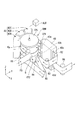
- FIG. 1 is a perspective view showing the configuration of the substrate processing apparatus FPA4 of the present embodiment.
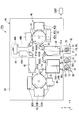
- FIG. 2 is a plan view showing the configuration of the substrate processing apparatus FPA4.
- the substrate processing apparatus FPA processes a substrate supply unit SU that supplies a sheet substrate (for example, a strip-shaped film member) FB, and a surface (surface to be processed) Fp of the sheet substrate FB.
- the substrate processing apparatus FPA is installed in a factory, for example. In the present embodiment, the sheet substrate FB is supplied, processed, and collected in an upright state.
- the standing state includes a state in which the processing surface Fp of the sheet substrate FB intersects the horizontal plane (XY plane) at a predetermined angle, for example, an inclined state or a state in which the surface is inclined substantially vertically.
- the state where the substrate processing surface Fp of the sheet substrate FB is raised includes a state where the short direction (short direction) of the substrate FB is in a non-horizontal posture.
- an XYZ orthogonal coordinate system is set, and the positional relationship of each member will be described with reference to this XYZ orthogonal coordinate system.
- the predetermined direction on the horizontal plane is the X-axis direction
- the direction orthogonal to the X-axis direction on the horizontal plane is the Y-axis direction
- the vertical direction is the Z-axis direction.
- the rotation (inclination) directions around the X axis, Y axis, and Z axis are the ⁇ X, ⁇ Y, and ⁇ Z directions, respectively.
- a description will be given of an example in which the substrate processing surface Fp of the sheet substrate FB is substantially perpendicular to the horizontal plane.
- the substrate processing apparatus FPA includes a surface of the sheet substrate FB from when the sheet substrate FB wound in a roll shape is sent out from the substrate supply unit SU until the sheet substrate FB is collected in a roll shape by the substrate recovery unit CL. And a roll-to-roll method (hereinafter simply referred to as “roll method”).
- the substrate processing apparatus FPA can be used when forming a display element (electronic device) such as an organic EL element or a liquid crystal display element on the sheet substrate FB. Of course, when forming elements other than these elements, the substrate processing apparatus FPA may be used.
- the sheet substrate FB to be processed in the substrate processing apparatus FPA for example, a foil such as a resin film or stainless steel can be used.
- the resin film is made of polyethylene resin, polypropylene resin, polyester resin, ethylene vinyl copolymer resin, polyvinyl chloride resin, cellulose resin, polyamide resin, polyimide resin, polycarbonate resin, polystyrene resin, vinyl acetate resin, etc. Can be used.
- the dimension in the short direction (short direction) of the sheet substrate FB is, for example, about 50 cm to 2 m, and the length in the long direction (longitudinal direction) is, for example, 10 m or more.
- this dimension is only an example and is not limited thereto.
- the dimension in the short direction of the sheet substrate FB may be 50 cm or less, or 2 m or more.
- substrate FB may be 10 m or less.
- the sheet substrate FB has a thickness of 1 mm or less, for example, and is formed to have flexibility.
- the term “flexibility” refers to the property that the substrate can be bent without being broken or broken even when a predetermined force of at least its own weight is applied to the substrate. Further, for example, the property of bending by the predetermined force is also included in the flexibility.
- the flexibility varies depending on the material, size, thickness, environment such as temperature, etc. of the substrate.
- substrate FB you may use the sheet
- the sheet substrate FB preferably has a smaller coefficient of thermal expansion so that, for example, the dimensions do not change substantially even when subjected to heat of about 200 ° C.
- an inorganic filler can be mixed with a resin film to reduce the thermal expansion coefficient.
- the inorganic filler include titanium oxide, zinc oxide, alumina, silicon oxide and the like.
- the substrate supply unit SU includes a supply port 10 (not shown in FIG. 1), and a shaft member 11 and a support unit 12 disposed in the supply port 10.
- the shaft member 11 is formed, for example, in a cylindrical shape, and is arranged so that the central axis is substantially parallel to, for example, the Z direction. For this reason, the shaft member 11 is wound with the sheet substrate FB standing upright.
- the shaft member 11 is provided so as to be detachable from the support portion 12, for example.
- the support portion 12 supports the shaft member 11 so as to be rotatable in the circumferential direction (for example, the ⁇ Z direction).
- the substrate supply unit SU for example, rolls the sheet substrate FB upright in the short direction of the sheet substrate FB, that is, aligned with the Z direction (in other words, the sheet substrate FB is in a non-horizontal posture). ) And sent to the substrate processing unit PR.
- a shaft member 13 around which a protective substrate PB for protecting the processing surface Fp of the sheet substrate FB is wound.
- the shaft member 13 provided in the supply port 10 may be referred to as a protective substrate supply unit.
- the protective substrate PB is a substrate that is attached to the sheet substrate FB after the processing in the substrate processing unit PR is completed and before being recovered by the substrate recovery unit CL. Similar to the sheet substrate FB, the protective substrate PB is formed in, for example, a belt shape and has a flexible structure.
- the shaft member 13 is formed in a cylindrical shape, for example, and is arranged so that the central axis is substantially parallel to the Z direction, for example. For this reason, the shaft member 13 is wound with the protective substrate PB standing upright.
- the shaft member 13 is supported by the support portion 14 so as to be rotatable in the circumferential direction (for example, the ⁇ Z direction).
- the shaft member 13 is provided so as to be detachable from the support portion 14, for example.
- the substrate supply unit SU sends out and supplies the substrate to the substrate processing unit PR with the protective substrate PB standing.
- the substrate collection unit CL collects and collects the sheet substrate FB transported from the substrate processing unit PR in a state where the protective substrate PB is pasted in a state where the sheet substrate FB and the protection substrate PB are set in the short direction. .
- a shaft member 21 for winding the sheet substrate FB and the protective substrate PB and the shaft member 21 are rotated around the recovery port 20 (not shown in FIG. 1) of the substrate recovery unit CL.
- the support part 22 which supports is provided.
- the shaft member 21 is detachably provided on the support portion 22, for example.
- the supply port 10 of the substrate supply unit SU and the recovery port 20 of the substrate recovery unit CL are arranged, for example, outside the chamber CB that houses the substrate processing unit PR.
- the supply port 10 and the recovery port 20 are disposed, for example, on the ⁇ Y side surface of the chamber CB, and are disposed side by side in the X direction, for example, with respect to the substrate processing unit PR.
- the supply port 10 and the collection port 20 are collectively arranged at one place, the supply port 10 and the collection port 20 can be efficiently accessed.
- the substrate processing unit PR conveys the sheet substrate FB supplied from the substrate supply unit SU to the substrate recovery unit CL in an upright state, and with respect to the processing surface Fp of the sheet substrate FB in the upright state.
- the substrate processing unit PR includes, for example, a transfer device 30 such as a transfer mechanism, a processing device 40, an alignment device (not shown), and the like.
- the substrate processing unit PR is housed in a clean chamber CB that is air-conditioned, and is managed so that the environmental temperature and the environmental humidity are constant, and the devices are protected from dust and the like.
- the transport device 30 includes a plurality (for example, six) of guide rollers R101 to R106 and two processing rollers 31 and 32.
- the guide rollers R101 to R104 guide the sheet substrate FB from the substrate supply unit SU to the substrate recovery unit CL.
- the guide rollers R105 and R106 guide the protective substrate PB from the substrate supply unit SU to the substrate recovery unit CL through a path different from the sheet substrate FB.
- the guide rollers R101 to R106 are arranged, for example, so that the rotation axis is substantially parallel to the Z-axis direction. For this reason, the guide rollers R101 to R104 are hung in a state where the sheet substrate FB stands up (as described above, the short direction of the substrate FB is substantially non-horizontal). Further, the guide rollers R105 and R106 are hung with the protective substrate PB standing upright.
- the guide rollers R101 to R106 may have a configuration provided with a drive mechanism, for example.
- the guide rollers R101 to R104 are wound around the processing surface Fp of the sheet substrate FB, for example, a gas layer forming device (not shown) that forms a gas layer on the cylindrical surface of each of the guide rollers R101 to R104 is provided. It does not matter as a configuration. With such a configuration, the sheet substrate FB is fed with a predetermined tension at least between the guide rollers R101 to R104.
- the processing rollers 31 and 32 are arranged on the guide path of the sheet substrate FB by the guide rollers R101 to R104, for example.
- the processing rollers 31 and 32 are arranged so that the positions in the Y direction are equal in the chamber CB.
- the processing rollers 31 and 32 are both disposed in a substantially central portion in the Y direction in the chamber CB.
- the processing rollers 31 and 32 are each formed in a cylindrical shape (for example, a drum shape having a diameter of about 1 to several meters).
- the processing rollers 31 and 32 are arranged so that the central axis is substantially parallel to the Z direction, and the processing rollers 31 and 32 are hung with the sheet substrate FB standing upright.
- the processing rollers 31 and 32 are formed to have a larger diameter than the guide rollers R101 to R104, for example.
- the processing rollers 31 and 32 are respectively provided at positions sandwiching the supply port SUa connected to the substrate supply unit SU and the recovery port CLa connected to the substrate recovery unit CL. More specifically, the processing roller 31 is disposed on the ⁇ X side of the supply port SUa, and the processing roller 32 is disposed on the + X side of the recovery port CLa.
- the sheet substrate FB in the substrate processing unit PR As the conveyance direction of the sheet substrate FB in the substrate processing unit PR, first, for example, the sheet substrate FB is conveyed in the + Y direction from the supply port SUa and is conveyed in the ⁇ X direction (a direction inclined 45 ° toward the ⁇ Y side) by the guide roller R101. Is converted.
- the sheet substrate FB that has passed through the guide roller R101 is folded back by the processing roller 31, and the transport direction is converted to the + X direction.
- the sheet substrate FB folded in the + X direction from the processing roller 31 is converted in the + Y direction by the guide roller R102, and the transfer direction is converted in the -Y direction by a part of the processing device 40 (preliminary processing device 44).
- the sheet substrate FB that has passed through the preliminary processing device 44 is changed in the conveyance direction in the + X direction by the guide roller R103, folded back by the processing roller 32, and converted in the -X direction (however, inclined by 45 ° to the + Y side). Is done.
- the sheet substrate FB that has passed through the processing roller 32 is converted in the -Y direction by the guide roller R104, and is conveyed to the recovery port CLa.
- the transport apparatus 30 transports the sheet substrate FB while frequently switching the transport direction between the X direction and the Y direction in the chamber CB.
- the processing apparatus 40 is an apparatus for forming, for example, an organic EL element on the processing surface Fp of the sheet substrate FB.
- a cleaning apparatus 41 for example, a TFT layer forming apparatus 42, a drying apparatus (drying unit) 43, a preliminary processing apparatus 44, a light emitting layer forming apparatus 45, a laminating apparatus 46, and the like are used.
- a drying apparatus (drying unit) 43 for example, a drying apparatus (drying unit) 43, a preliminary processing apparatus 44, a light emitting layer forming apparatus 45, a laminating apparatus 46, and the like are used.
- another apparatus such as a partition forming apparatus (not shown) for forming the partition on the processing surface Fp may be provided.
- Examples of such a processing apparatus 40 include film forming apparatuses such as a droplet applying apparatus (for example, an ink jet type applying apparatus and a screen printing type applying apparatus), a vapor deposition apparatus, a sputtering apparatus, an exposure apparatus, a developing apparatus, and a surface.
- film forming apparatuses such as a droplet applying apparatus (for example, an ink jet type applying apparatus and a screen printing type applying apparatus), a vapor deposition apparatus, a sputtering apparatus, an exposure apparatus, a developing apparatus, and a surface.
- Various apparatuses such as a reforming apparatus and a cleaning apparatus are used. Each of these apparatuses is appropriately provided, for example, on the conveyance path of the sheet substrate FB.
- the cleaning device 41 includes a first cleaning device 41A that cleans the sheet substrate FB and a second cleaning device 41B that cleans the protective substrate PB.
- the first cleaning device 41A is provided, for example, between the supply port SUa (see FIG. 2) and the processing roller 31 in the conveyance path of the sheet substrate FB.
- the second cleaning device 41B is provided, for example, between the supply port SUb and the laminating device 46 in the transport path of the protective substrate PB.
- the cleaning device 41 cleans the sheet substrate FB and the protective substrate PB supplied from the outside to the inside of the chamber CB.
- the TFT layer forming device 42 is a device for forming TFT elements and electrodes for driving organic EL elements.
- the TFT layer forming device 42 includes, for example, a first forming device 42A, a second forming device 42B, and a third forming device 42C.
- the first forming device 42A is disposed on the ⁇ Y side of the processing roller 31.
- the second forming device 42B is disposed on the ⁇ X side of the processing roller 31.
- the third forming device 42 ⁇ / b> C is disposed on the + Y side of the processing roller 31.
- the + X side of the processing roller 31 is in an empty state, for example, a guide roller R101 is arranged.
- the first forming device 42A, the second forming device 42B, and the third forming device 42C are provided, for example, around the processing roller 31.
- a series of steps for forming the TFT element and the electrode is performed by, for example, the first forming device 42A, the second forming device 42B, and the third forming device 42C.
- the first forming device 42A, the second forming device 42B, and the third forming device 42C are respectively directed to the processing roller 31, and can process the sheet substrate FB wound around the processing roller 31 in an upright state. It has become.
- the processing roller 31 serves as a support portion that supports the sheet substrate FB when processing by the TFT layer forming apparatus 42 is performed.
- the drying device 43 is a device that stabilizes TFT elements, electrodes, and the like formed on the sheet substrate FB by heating the sheet substrate FB, for example.
- the drying device 43 is disposed between the processing roller 31 and the processing roller 32 in the conveyance path of the sheet substrate FB.
- the drying device 43 is disposed so as to partially overlap the processing roller 31 and the processing roller 32 when viewed in the Y direction.
- the preliminary processing apparatus 44 is an apparatus that performs a preliminary process (for example, an insulating layer forming process) when forming a light emitting layer on the sheet substrate FB.
- the preliminary processing device 44 is disposed, for example, between the processing roller 31 and the processing roller 32 together with the drying device 43 in the conveyance path of the sheet substrate FB.
- the preliminary processing device 44 includes, for example, a first processing device 44A, a second processing device 44B, and a third processing device 44C, and a series of preliminary processing steps are performed in a shared manner.
- the light emitting layer forming device 45 is a device for forming a light emitting layer constituting an organic EL element.
- the light emitting layer forming device 45 includes, for example, a first forming device 45A, a second forming device 45B, and a third forming device 45C.
- the first forming device 45A, the second forming device 45B, and the third forming device 45C are provided, for example, around the processing roller 32.
- a series of steps for forming the light emitting layer is performed by, for example, the first forming device 45A, the second forming device 45B, and the third forming device 45C.
- the first forming device 45A is disposed on the + Y side of the processing roller 32.
- the second forming device 45 ⁇ / b> B is disposed on the + X side of the processing roller 32.
- the third forming device 45C is disposed on the ⁇ Y side of the processing roller 32.
- the -X side of the processing roller 32 is in an empty state, for example, a guide roller R104 is disposed.
- the laminating device 46 is a device that bonds the sheet substrate FB and the protective substrate (protective material) PB together.
- the laminating device 46 is disposed, for example, between the processing roller 32 and the recovery port CLa in the conveyance path of the sheet substrate FB.
- the laminating device 46 arranges the protective substrate PB so as to face the processing surface Fp side of the sheet substrate FB, and performs alignment between the sheet substrate FB and the protective substrate PB. Are configured to be bonded together.
- the first forming device 42A of the TFT layer forming device 42, the first cleaning device 41A, the second cleaning device 41B, and the third forming device 45C of the light emitting layer forming device 45 are X. They are arranged so as to overlap in the direction. Further, the second forming device 42B of the TFT layer forming device 42, the processing roller 31, the processing roller 32, and the second forming device 45B of the light emitting layer forming device 45 are arranged so as to overlap each other when viewed in the X direction. . Further, the third forming device 42C of the TFT layer forming device 42, the drying device 43, and the first forming device 45A of the light emitting layer forming device 45 are arranged so as to overlap each other when viewed in the X direction.
- the first forming device 42A of the TFT layer forming device 42, the processing roller 31, and the third forming device 42C are arranged so as to overlap each other when viewed in the Y direction.
- the cleaning devices 41A and 41B and the drying device 43 are arranged so as to overlap each other when viewed in the Y direction.
- the preliminary processing device 44 and the laminating device 46 are arranged so as to overlap each other when viewed in the Y direction.
- the first forming device 45A, the processing roller 32, and the third forming device 45C of the light emitting layer forming device 45 are arranged so as to overlap each other when viewed in the Y direction.
- the transport device 30 and the processing device 40 are densely arranged so that there are many overlapping portions when viewed in the X direction and the Y direction.
- the substrate processing apparatus FPA configured as described above manufactures display elements (electronic devices) such as organic EL elements and liquid crystal display elements by a roll method under the control of the control unit CONT.
- display elements electronic devices
- CONT control unit
- the belt-like sheet substrate FB wound around the shaft member 11 in a roll shape is attached to the support portion 12 in the supply port 10 of the substrate supply portion SU. Further, the band-shaped protective substrate PB wound around the shaft member 13 is attached to the support portion 14 in the supply port 10 of the substrate supply portion SU. Further, the recovery shaft member 21 is attached to the support portion 22 in the recovery port 20 of the substrate recovery portion CL.
- the control unit CONT rotates the shaft member 11 through the support unit 12 from this state so that the sheet substrate FB is sent out from the substrate supply unit SU.
- the sheet substrate FB sent out from the substrate supply unit SU is supplied into the chamber CB from the supply port SUa of the substrate processing unit PR.
- the control unit CONT causes each processing apparatus 40 to perform processing on the sheet substrate FB while transporting the sheet substrate FB supplied into the chamber CB to the transport apparatus 30.
- the control unit CONT controls each motor so that a predetermined tension is applied to the sheet substrate FB by the rotation rollers provided appropriately for the processing rollers 31 and 32 and the rollers R101 to R106. Control sequentially.
- the sheet substrate FB supplied to the substrate processing unit PR is cleaned by the first cleaning device 41A and guided to the processing roller 31 by the guide roller R101.
- the sheet substrate FB is wound while standing on the processing roller 31 so that the processing surface Fp is directed to the first forming device 42A, the second forming device 42B, and the third forming device 42C of the TFT layer forming device 42, respectively. It is done.
- a TFT element, wiring, and the like are formed by the TFT layer forming device 42 on the processing surface Fp of the sheet substrate FB wound around the processing roller 31.
- the sheet substrate FB that has passed through the processing roller 31 is supplied to the drying device 43 and subjected to a drying process such as a heating process.
- the sheet substrate FB after the drying process is supplied to the preliminary processing device 44 via, for example, a guide roller R102.
- an insulating film, a hole injection layer, an electron injection layer, or the like is formed on the sheet substrate FB.
- the pre-processed sheet substrate FB is guided to the processing roller 32 via, for example, a guide roller R103.
- the sheet substrate FB is wound in a standing state on the processing roller 32 so that the processing surface Fp is directed to the first forming device 45A, the second forming device 45B, and the third forming device 45C of the light emitting layer forming device 45, respectively. It is done.
- a light emitting layer or the like is formed by the light emitting layer forming device 45 on the processing surface Fp of the sheet substrate FB wound around the processing roller 32.
- the sheet substrate FB that has passed through the processing roller 32 is supplied to the laminating apparatus 46, and the protective substrate PB is attached to the processing surface Fp.
- the sheet substrate FB after the protective substrate (protective material) PB is attached is recovered, for example, from the recovery port CLa to the substrate recovery unit CL.
- the sheet substrate FB recovered by the substrate recovery unit CL is wound around the shaft member 21 in the recovery port 20 in a roll shape.
- the sheet substrate FB is cut, for example, and the shaft member 21 wound with the sheet substrate FB is removed from the support portion 22.
- a new shaft member 21 around which the sheet substrate FB is not wound is attached to the support portion 22.
- the control unit CONT forms elements on the processing surface Fp of the sheet substrate FB by performing such processing.
- the substrate supply unit SU that supplies the sheet substrate FB in a state where the short direction of the sheet substrate FB formed in a strip shape is set, and the substrate supply unit SU is supplied.
- the processing is performed on the transport apparatus 30 that transports the sheet substrate FB in a standing state, and the processing surface Fp of the sheet substrate FB that is placed along the transport path of the sheet substrate FB by the transport apparatus 30. Since a substrate processing unit PR having a plurality of processing apparatuses 40 to be performed and a substrate recovery unit CL that recovers the sheet substrate FB processed by the substrate processing unit PR in an upright state, the sheet substrate FB is conveyed. It becomes the structure which is easy to convert a direction into a horizontal direction (X direction and Y direction).
- the range of selection of the layout in the X direction and the Y direction of the processing apparatus 40 can be widened.
- the layout in which the processing apparatus 40 is arranged so that the apparatus area of the substrate processing apparatus FPA4 becomes as small as possible can be selected. it can. Thereby, space saving of the substrate processing apparatus FPA4 can be achieved.
- FIG. 3 is a plan view showing the configuration of the substrate processing apparatus FPA2.
- the configuration of the substrate processing unit PR is different from that of the first embodiment.
- it can be set as the same structure as 1st embodiment, for example. In the present embodiment, the difference will be mainly described.
- the substrate processing apparatus FPA2 includes a substrate supply unit SU, a substrate processing unit PR, a substrate recovery unit CL, a chamber CB, and a control unit CONT.
- the substrate processing part PR is accommodated in the chamber CB.
- the substrate supply unit SU includes a shaft member 111 that is formed in a cylindrical shape and has a central axis that is parallel to the Z direction, and a support unit 112 that rotatably supports the shaft member 111.
- a sheet substrate FB is wound around the shaft member 111 in an upright state.
- FIG. 3 does not show the configuration for supplying the protective substrate in the substrate supply unit SU.
- the substrate recovery part CL includes a shaft member 121 that is formed in a cylindrical shape and has a central axis that is parallel to the Z direction, and a support part 122 that rotatably supports the shaft member 21.
- the transfer device 130 of the substrate processing unit PR has a processing transfer roller 131 at the center in a plan view inside the chamber CB.
- the processing conveyance roller 131 is formed in a cylindrical shape, for example, and is arranged so that the central axis is parallel to the Z direction.
- the processing conveyance roller 131 is provided to be rotatable in the ⁇ Z direction, for example.
- the sheet substrate FB is hung while standing on the processing conveyance roller 131. Thus, in the substrate processing part PR, the sheet substrate FB is conveyed in a standing state.
- the processing transport roller 131 has, for example, a rotation drive mechanism (not shown).
- the rotational drive mechanism is controlled by, for example, the control unit CONT.
- the sheet substrate FB supplied from the supply port SUa is hung on the processing transport roller 131 and transported to the recovery port CLa.
- the sheet substrate FB is hung on the processing conveyance roller 131 so that the processing surface Fp faces outward.
- a plurality of processing apparatuses 140 are arranged around the processing transport roller 131 so as to follow the cylindrical surface of the processing transport roller 131.
- the processing device 140 for example, various processing devices described in the first embodiment are used.
- each processing device that performs the TFT layer forming step, each processing device that performs the pretreatment (preliminary step) of the light emitting layer forming step, and each processing device that performs the light emitting layer forming step They are arranged in a line along the circumferential direction of the processing conveyance roller 131.
- the plurality of processing apparatuses 140 are each directed to the processing conveyance roller 131.
- the sheet substrate FB is supplied in a state where the substrate supply unit SU stands up to the substrate processing unit PR.
- the sheet substrate FB is hung on the processing conveyance roller 131 in the substrate processing unit PR and conveyed to the substrate recovery unit CL. Further, for example, the processing is sequentially performed on the sheet substrate FB hung on the processing conveyance roller 131 by the plurality of processing apparatuses 140.
- the processing conveyance roller 131 has a function of supporting the sheet substrate FB wound in the standing state and a function of conveying the sheet substrate FB in the standing state. .
- space saving of the substrate processing apparatus FPA2 can be achieved.
- the layout of the apparatus in the substrate processing unit PR can be simplified.
- FIG. 4 is a plan view showing the configuration of the substrate processing apparatus FPA3.
- the configuration of the substrate processing unit PR is different from that of the first embodiment.
- it can be set as the same structure as 1st embodiment, for example. In the present embodiment, the difference will be mainly described.
- the substrate processing apparatus FPA3 has a configuration in which a plurality of processing conveyance rollers described in the second embodiment are provided in the substrate processing unit PR.
- the transport device 230 of the substrate processing unit PR includes guide rollers R111 to R114 and processing transport rollers 231 to 233.
- the guide rollers R111 to R114 and the processing transport rollers 231 to 233 are each formed in a cylindrical shape, and are arranged so that the central axes are parallel to the Z direction.
- the processing transport rollers 231 to 233 are formed to have a larger diameter than the guide rollers R111 to R114.
- the sheet substrate FB is hung on the processing transport rollers 231 to 233 and the guide rollers R111 to R114 in a standing state. Thus, in the substrate processing part PR, the sheet substrate FB is conveyed in a standing state.
- the guide rollers R111 to R114 are arranged in a state where two rows are arranged vertically and horizontally in the substantially central portion of the chamber CB. Further, the processing conveyance rollers 231 to 233 are arranged so as to surround the four guide rollers R111 to R114 from three directions ( ⁇ X direction, + Y direction, and ⁇ X direction).
- a plurality of processing devices 241 to 243 are arranged around the processing transport rollers 231 to 233 so as to follow the cylindrical surfaces of the processing transport rollers 231 to 233, respectively.
- the processing devices 241 to 243 for example, various processing devices described in the first embodiment are used.
- each processing apparatus that performs the TFT layer forming process is used as the processing apparatus 241
- each processing apparatus that performs a pretreatment (preliminary process) of the light emitting layer forming process is used as the processing apparatus 242
- the light emitting layer forming process is performed as the processing apparatus 243. You may make it use each processing apparatus to perform.
- the processing devices 241 to 243 are directed to the processing transport rollers 231 to 233, for example.
- the plurality of processing transport rollers 231 to 233 are formed in a cylindrical shape, for example, and are arranged so that the central axis is parallel to the Z direction.
- the processing conveyance roller 131 is provided to be rotatable in the ⁇ Z direction, for example.
- the processing transport rollers 231 to 233 have, for example, a rotation drive mechanism (not shown).
- the rotational drive mechanism is controlled by, for example, the control unit CONT.
- the sheet substrate FB supplied from the supply port SUa is hung on the processing transport rollers 231 to 233 and transported to the recovery port CLa.
- the sheet substrate FB is hung on the processing conveyance rollers 231 to 233 so that the processing surface Fp faces outward.
- the sheet substrate FB is hung on the guide rollers R111 to R114 so that the processing surface Fp faces inward.
- the sheet substrate FB is supplied in a state where the substrate supply unit SU stands up to the substrate processing unit PR.
- the sheet substrate FB is hung on the processing transport rollers 231 to 233 in the substrate processing section PR and transported to the substrate recovery section CL.
- the plurality of processing apparatuses 241 to 243 sequentially perform processing on the sheet substrate FB hung on the processing transport rollers 231 to 233, for example.
- the present embodiment by using the plurality of processing conveyance rollers 231 to 233, for example, in a plurality of areas, it is possible to perform continuous processing. This widens the range of layout selections. Further, according to the present embodiment, since the guide rollers R111 to R114 are collected in the central part of the chamber CB, for example, by disposing a processing device 244 such as a drying device in the central part of the chamber CB, Processing such as drying processing of the sheet substrate FB processed by each of the processing conveyance rollers 231 to 233 can be made common. Thereby, space saving can be achieved.
- FIG. 5 is a perspective view showing the configuration of the substrate processing apparatus FPA.
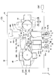
- FIG. 6 is a plan view showing the configuration of the substrate processing apparatus FPA.
- the transport device 30 includes a plurality of (for example, 10) guide rollers R1 to R10, a drum mechanism DRM, and a processing roller 32.
- the guide rollers R1 to R8 guide the sheet substrate FB from the substrate supply unit SU to the substrate recovery unit CL.
- the guide rollers R9 and R10 guide the protective substrate PB from the substrate supply unit SU to the substrate recovery unit CL through a path different from the sheet substrate FB.
- the drum mechanism DRM may be the first drum mechanism and the processing roller 32 may be the second drum mechanism.
- the guide rollers R1 to R3 and R6 to R10 are arranged, for example, such that the rotation axis is substantially parallel to the Z-axis direction. Therefore, the guide rollers R1 to R3 and R6 to R8 are hung with the sheet substrate FB standing upright. Further, the guide rollers R9 and R10 are hung with the protective substrate PB standing upright.
- the guide rollers R1 to R10 may have a configuration provided with a drive mechanism, for example.
- a gas layer forming device (not shown) that forms a gas layer (air bearing) on the cylindrical surface may be provided. I do not care.
- the sheet substrate FB is fed with a predetermined tension at least between the guide rollers R1 to R9.
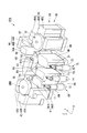
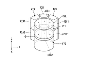
- FIG. 7 is a perspective view showing a configuration in the vicinity of the drum mechanism DRM in the substrate processing unit PR.
- the drum mechanism DRM includes a cylindrical member CYL disposed so that the rotation center axis is substantially parallel to the Z direction, and a rotational drive mechanism that supports the cylindrical member CYL so as to be rotatable in the circumferential direction.
- Driver ACT.
- the cylindrical member CYL has a first cylindrical portion (first roller) CY1, a second cylindrical portion (second roller) CY2, and a guide portion G.
- the first cylindrical part CY1 and the second cylindrical part CY2 are part of the cylindrical surface of the cylindrical member CYL. Since the first cylindrical portion CY1 and the second cylindrical portion CY2 are both part of one cylindrical member CYL, the first cylindrical portion CY1 and the second cylindrical portion CY2 rotate integrally when the cylindrical member CYL rotates. It has become.
- the first cylindrical part CY1 and the second cylindrical part CY2 are divided in the Z direction by a guide part G, for example.
- the second cylindrical portion CY2 is different from the first cylindrical portion CY1 in the position in the Z direction, that is, in the direction intersecting the horizontal direction.
- the first cylindrical part CY1 is arranged on the + Z side (upper side) of the guide part G, and the second cylindrical part CY2 is arranged on the ⁇ Z side (lower side) of the guide part G.
- the first cylindrical part CY1 and the second cylindrical part CY2 are formed so as to have the same diameter, for example.
- the first cylindrical portion CY1 and the second cylindrical portion CY2 are formed to have a larger diameter (for example, a diameter of 1 m or more) than the guide rollers R1 to R10, for example.
- the guide part G guides the sheet substrate FB so that the part wound around the first cylindrical part CY1 and the part wound around the second cylindrical part CY2 are conveyed along a plane parallel to the XY plane.
- guide rollers R2 to R5 are disposed between the first cylindrical portion CY1 and the second cylindrical portion CY2.
- the guide roller R2 is folded back in the ⁇ Y direction by the first cylindrical portion CY1 and folded back in a U-shape about a half circumference and conveyed in the + X direction.
- the guide roller R3 folds the sheet substrate FB folded in the ⁇ Y direction in the ⁇ X direction.
- the guide rollers R4 and R5 are arranged, for example, with the + Z side end inclined to the + X side.
- the guide roller R4 folds back the sheet substrate FB guided in the ⁇ X direction via the guide roller R3 in an obliquely downward direction (a direction tilted toward the ⁇ Z side in the + X direction).
- the guide roller R5 is disposed obliquely below the guide roller R4 (the + X direction and the direction inclined to the ⁇ Z side).
- the guide roller R5 folds the sheet substrate FB conveyed obliquely downward from the guide roller R4 in the ⁇ X direction and directs it toward the second cylindrical portion CY2.
- the guide rollers R4 and R5 are set so that their rotational axes are substantially parallel to each other and are inclined by a predetermined amount in the XZ plane.
- the guide rollers R4 and R5 are provided with an actuator for making it possible to adjust the inclination (inclination amount and inclination direction) of the rotating shaft, for example.
- the tilt state of at least one of the rotation shafts of the guide rollers R4 and R5 is adjusted by, for example, measuring signals from a sensor that precisely monitors changes in the posture and position of the sheet substrate FB sent in the ⁇ X direction from the guide roller R5.
- the received control unit CONT can be controlled by driving an actuator for tilt adjustment.
- the guide rollers R2 to R5 are arranged so that the conveying direction of the sheet substrate FB after being wound around the outer peripheral surface of the first cylindrical portion CY1 is the direction toward the second cylindrical portion CY2. Change the transport direction.
- the pair of guide rollers R4 and R5 does not change the feeding direction ( ⁇ X direction) of the sheet substrate FB, and the height position in the Z direction is a predetermined amount (in this embodiment, more than the width of the sheet substrate in the Z direction). ) Can only be shifted.
- the sheet substrate FB is inclined between the guide rollers R4 and R5 in the XZ plane.
- the sheet substrate FB is guided by the guide rollers R2 to R5 to, for example, a space on the ⁇ Z side (lower side) of the sheet substrate FB guided at the position of the guide roller R1.
- the winding direction of the sheet substrate FB around the second cylindrical portion CY2 is the same as the winding direction of the sheet substrate FB around the first cylindrical portion CY1, and the front and back sides of the sheet substrate FB are reversed.
- the sheet substrate FB is guided by the guide rollers R2 to R5.
- the processing roller 32 is arranged on the guide path of the sheet substrate FB by the guide rollers R1 to R4, for example.
- the processing roller 32 is formed in a cylindrical shape, for example.
- the processing roller 32 is arranged so that the central axis thereof is substantially parallel to the Z direction, and is hung with the sheet substrate FB standing upright.
- the processing roller 32 is formed to have a larger diameter than the guide rollers R1 to R10, for example. You may comprise so that the diameter of the said processing roller 32 may become a diameter substantially equal to said 1st cylindrical part CY1 and 2nd cylindrical part CY2.
- the cleaning device 41 is provided to clean the sheet substrate FB and the protective substrate PB supplied from the outside to the inside of the chamber CB, and cleans the first cleaning device 41A for cleaning the sheet substrate FB and the protective substrate PB. And a second cleaning device 41B.
- the first cleaning device 41A is provided, for example, between the supply port SUa (see FIG. 6) and the cylindrical member CYL in the conveyance path of the sheet substrate FB.
- the second cleaning device 41B is provided, for example, between the supply port SUb and the laminating device 46 in the transport path of the protective substrate PB.
- the TFT layer forming device 42 arranged around the drum mechanism DRM is a device for forming TFT elements, electrodes, wiring layers, and the like for driving the organic EL elements.
- the TFT layer forming device 42 includes, for example, a first forming device 42A, a second forming device 42B, and a third forming device 42C.
- the first forming device 42A is disposed on the ⁇ Y side of the cylindrical member CYL.
- the second forming device 42B is disposed on the ⁇ X side of the cylindrical member CYL.
- the third forming device 42C is disposed on the + Y side of the cylindrical member CYL.
- the first forming device 42A, the second forming device 42B, and the third forming device 42C are provided around the cylindrical member CYL, and a series of steps for forming the TFT element, the electrode, the wiring layer, etc.
- the formation is performed by the forming device 42A, the second forming device 42B, and the third forming device 42C.
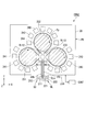
- FIG. 8 is a diagram illustrating a relationship between the first forming device 42A, the second forming device 42B, the third forming device 42C, and the cylindrical member CYL of the drum mechanism DRM.
- the first forming apparatus 42A, the second forming apparatus 42B, and the third forming apparatus 42C each have two processing units 42A1 and 42A2, processing units 42B1 and 42B2, and processing units 42C1 and 42C2. Yes.
- the processing units 42A1, 42B1, and 42C1 are provided to face the first cylindrical portion CY1, respectively, and can process the sheet substrate FB hung on the first cylindrical portion CY1.
- the processing units 42A2, 42B2, and 42C2 are provided to face the second cylindrical portion CY2, respectively, and can process the sheet substrate FB hung on the second cylindrical portion CY2.
- the first forming device 42A, the second forming device 42B, and the third forming device 42C can process the sheet substrate FB wound in an upright state.
- the first cylindrical portion CY1 and the second cylindrical portion CY2 serve as support portions that support the sheet substrate FB when processing by the TFT layer forming apparatus 42 is performed. Further, when the first cylindrical portion CY1 and the second cylindrical portion CY2 serve as support portions that support the sheet substrate FB, the drum mechanism can be paraphrased as a support mechanism.
- the drying device 43 is a device that stabilizes TFT elements, electrodes, and the like formed on the sheet substrate FB by heating the sheet substrate FB, for example.
- two insertion ports 43a and 43b are provided as shown in FIG.
- the insertion port 43a is disposed on the + Z side, and the sheet substrate FB that has passed through the first cylindrical portion CY1 is inserted therein.
- the insertion port 43b is disposed on the ⁇ Z side, and the sheet substrate FB that has passed through the second cylindrical portion CY2 is inserted therein.
- Two discharge ports 43c and 43d are provided on the surface of the drying device 43 on the + X side.
- the discharge port 43c is disposed on the + Z side, and the sheet substrate FB that has been inserted through the insertion port 43a and subjected to a drying process is discharged.
- the discharge port 43d is disposed on the ⁇ Z side, and the sheet substrate FB that has been inserted and inserted through the insertion port 43b and discharged is discharged.
- the preliminary processing apparatus 44 is an apparatus that performs a preliminary process (for example, an insulating layer forming process) when forming the light emitting layer on the sheet substrate FB.
- the preliminary processing device 44 is disposed, for example, between the cylindrical member CYL of the drum mechanism DRM and the processing roller 32 together with the drying device 43 in the conveyance path of the sheet substrate FB.
- the preliminary processing device 44 includes, for example, a first processing device 44A, a second processing device 44B, and a third processing device 44C, and a series of preliminary processing steps are performed in a shared manner.
- the first forming device 42A of the TFT layer forming device 42, the first cleaning device 41A, the second cleaning device 41B, and the third forming device 45C of the light emitting layer forming device 45 are the first. Arranged along one direction (X direction as the first direction in the present embodiment). Further, the second forming device 42B of the TFT layer forming device 42, the cylindrical member CYL, the processing roller 32, and the second forming device 45B of the light emitting layer forming device 45 are arranged along the X direction. Furthermore, a third forming device 42C of the TFT layer forming device 42, a drying device 43, and a first forming device 45A of the light emitting layer forming device 45 are arranged along the X direction.
- the first forming device 42A of the TFT layer forming device 42, the cylindrical member CYL, and the third forming device 42C are arranged along the second direction (Y direction intersecting the X direction in the present embodiment). Yes. Further, for example, the cleaning devices 41A and 41B and the drying device 43 are arranged along the Y direction. Moreover, the preliminary processing apparatus 44 and the laminating apparatus 46 are arrange
- the substrate processing apparatus FPA configured as described above manufactures display elements (electronic devices) such as organic EL elements and liquid crystal display elements by a roll method under the control of the control unit CONT.
- display elements electronic devices
- CONT control unit
- the belt-like sheet substrate FB wound around the shaft member 11 in a roll shape is attached to the support portion 12 in the supply port 10 of the substrate supply portion SU. Further, the band-shaped protective substrate PB wound around the shaft member 13 is attached to the support portion 14 in the supply port 10 of the substrate supply portion SU. Further, the recovery shaft member 21 is attached to the support portion 22 in the recovery port 20 of the substrate recovery portion CL.
- the control unit CONT rotates the shaft member 11 through the support unit 12 from this state so that the sheet substrate FB is sent out from the substrate supply unit SU.
- the sheet substrate FB sent out from the substrate supply unit SU is supplied into the chamber CB from the supply port SUa of the substrate processing unit PR.
- the control unit CONT causes each processing apparatus 40 to perform processing on the sheet substrate FB while transporting the sheet substrate FB supplied into the chamber CB to the transport apparatus 30.
- a leader sheet for facilitating automatic loading of the sheet substrate to the processing apparatus FPA may be attached to the front end portion and the end portion of the sheet substrate FB wound around the shaft member 11 in a roll shape. .
- the sheet substrate FB supplied to the substrate processing unit PR is cleaned by the first cleaning device 41A and guided to the first cylindrical portion CY1 of the drum mechanism DRM by the guide roller R1.
- the sheet substrate FB stands in the first cylindrical portion CY1 so that the processing surface Fp is directed to the first forming device 42A, the second forming device 42B, and the third forming device 42C of the TFT layer forming device 42, respectively. Wrapped.
- the TFT layer forming device 42 (for example, the processing units A1, B1, and C1) forms TFT elements and wirings on the processing surface Fp of the sheet substrate FB wound around the first cylindrical portion CY1.
- the sheet substrate FB having passed through the first cylindrical portion CY1 is supplied into the drying device 43 from the + Z side insertion port 43a of the drying device 43, and is subjected to a drying process such as a heating process.
- the sheet substrate FB after the drying process is carried out from the + Z side discharge port 43 c of the drying device 43.
- the unloaded sheet substrate FB is guided, for example, in the ⁇ Y direction by the guide roller R2, and is guided in the ⁇ X direction by the guide roller R3.
- the sheet substrate FB via the guide roller R3 is guided obliquely downward (in the + X direction and inclined to the ⁇ Z side) by the guide roller R4, and is guided in the ⁇ X direction by the guide roller R5.
- the sheet substrate FB via the guide roller R5 is wound in a standing state on the second cylindrical portion CY2 of the drum mechanism DRM.
- Layers necessary for TFT elements and wirings are superimposed on the processing surface Fp of the sheet substrate FB wound around the second cylindrical portion CY2 by the TFT layer forming device 42 (for example, the processing portions A2, B2, and C2). Formed.
- the sheet substrate FB having passed through the second cylindrical portion CY2 is supplied into the drying device 43 from the insertion port 43b on the ⁇ Z side of the drying device 43, and subjected to drying processing such as heat treatment again.
- the sheet substrate FB after the drying process is carried out from the discharge port 43d on the ⁇ Z side of the drying device 43.
- the unloaded sheet substrate FB is supplied to the preliminary processing device 44 through, for example, a guide roller R6.
- an insulating film, a hole injection layer, an electron injection layer, or the like is formed on the sheet substrate FB.
- the sheet substrate FB after the preliminary processing is guided to the processing roller 32 through, for example, a guide roller R7.
- the sheet substrate FB is wound in a standing state on the processing roller 32 so that the processing surface Fp is directed to the first forming device 45A, the second forming device 45B, and the third forming device 45C of the light emitting layer forming device 45, respectively. It is done.
- a light emitting layer or the like is formed by the light emitting layer forming device 45 on the processing surface Fp of the sheet substrate FB wound around the processing roller 32.
- the sheet substrate FB that has passed through the processing roller 32 is supplied to the laminating apparatus 46, and the protective substrate PB is attached to the processing surface Fp.
- the sheet substrate FB after the protective substrate PB is attached is recovered to the substrate recovery part CL from the recovery port CLa, for example.
- the sheet substrate FB recovered by the substrate recovery unit CL is wound around the shaft member 21 in the recovery port 20 in a roll shape.
- the sheet substrate FB is cut, for example, and the shaft member 21 wound with the sheet substrate FB is removed from the support portion 22.
- a new shaft member 21 around which the sheet substrate FB is not wound is attached to the support portion 22.
- the control unit CONT forms elements on the processing surface Fp of the sheet substrate FB by performing such processing.
- the conveyance direction of the sheet substrate FB is set to the second cylindrical portion CY2.
- the sheet substrate FB is wound around the second cylindrical portion CY2, the first processing is performed on the processing surface Fp wound around a part of the first cylindrical portion CY1, and the second cylindrical portion Since the second process is performed on the processing target surface Fp wound around a part, the sheet substrate FB can be processed with a high density. Thereby, space saving of the substrate processing apparatus FPA can be achieved.
- the sheet substrate FB is wound only once in the processing roller 32, but the first cylindrical portion and the first cylindrical portion CYL are similar to the cylindrical member CYL of the drum mechanism DRM.
- a two-stage cylindrical portion having two cylindrical portions may be used, and the sheet substrate FB may be wound around each cylindrical portion. Furthermore, in this structure, you may make it arrange
- the sheet substrate FB is formed by using two guide rollers whose respective rotation center axes are inclined like the guide rollers R4 and R5 shown in FIG. Can be folded.
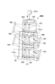
- FIG. 9 is a perspective view showing a configuration of the drum mechanism DRM2 according to the present embodiment.
- the first cylindrical member C1 and the second cylindrical member C2 are arranged in a state of being separated in the Z direction.
- the + Z side end face C1a of the first cylindrical member C1 and the ⁇ Z side end face C2a of the second cylindrical member C2 face each other.
- the center line of the rotation axis SF is provided so as to be common (the same position in the XY plane) between the first cylindrical member C1 and the second cylindrical member C2.
- the diameter is different between the first cylindrical member C1 and the second cylindrical member C2.
- the diameter D1 of the first cylindrical member C1 is larger than the diameter D2 of the second cylindrical member C2.
- route can be adjusted because the 1st cylindrical member C1 and the 2nd cylindrical member C2 have a different diameter.
- Rotational drive mechanism ACT2 may be configured to be capable of independently rotating first cylindrical member C1 and second cylindrical member C2. Further, the rotational drive mechanism ACT2 may be configured to be able to rotate only one of the first cylindrical member C1 and the second cylindrical member C2.
- the sheet substrate FB via the guide roller R21 is wound around the first cylindrical portion CY1, and is guided to the second cylindrical portion CY2 via the guide rollers (conversion units) R22 and R23.
- the sheet substrate FB after being wound around the second cylindrical portion CY2 is guided via the guide roller R24.
- the difference in diameter between the first cylindrical member C1 and the second cylindrical member C2 is that the processing modes and processing conditions of various processing apparatuses arranged around the cylindrical members C1 and C2 and the installation of processing parts (processing head parts, etc.) It can occur depending on the size and the like.
- the continuous sheet substrate FB is sent from the first cylindrical member C1 to the second cylindrical member C2, when the diameters of the cylindrical members C1 and C2 are different, it corresponds to the difference in diameter. Therefore, it is necessary to provide a difference in the rotation speed (rpm).
- the first cylindrical member C1 and the second cylindrical member C2 are arranged from the portion contacting the first cylindrical member C1 of the sheet substrate FB. It is possible to apply a predetermined tension to the portion in contact with the two cylindrical members C2.
- the first cylindrical member C1 is arranged on the ⁇ Z side, and the second cylindrical member C2 is arranged on the + Z side.
- One cylindrical member C1 may be disposed on the + Z side, and the second cylindrical member C2 may be disposed on the ⁇ Z side.
- FIG. 10 is a perspective view showing a configuration of the drum mechanism DRM3 according to the present embodiment.
- the drum mechanism DRM3 has a configuration in which a plurality of second cylindrical portions (processing reference surfaces) separated from the first cylindrical portion (processing reference surface) CY1 are arranged. It has become. Specifically, the drum mechanism DRM3 has a configuration in which two second cylindrical portions CY21 and CY22 are arranged with respect to the first cylindrical portion CY1. In the present embodiment, the first cylindrical portion CY1 and the second cylindrical portions CY21, CY22 are formed in different cylindrical members (for example, the first cylindrical member C1 and the second cylindrical members C21, C22).
- the drum mechanism DRM3 has a configuration in which two second cylindrical members C21 and C22 are arranged on the + Z side of the first cylindrical member C1.
- the two second cylindrical members C21 and C22 are formed to have the same diameters D4 and D5, for example.
- the diameter D3 of the first cylindrical member C1 is formed to be larger than these diameters D4 and D5.
- the first cylindrical member C1 and the second cylindrical members C21 and C22 are arranged in a state of being separated in the Z direction.
- the first cylindrical member C1 and the second cylindrical members C21, C22 have separate rotation axes SF1, SF21, SF22, respectively.
- the rotation axis SF1, the rotation axis SF21, and the rotation axis SF22 are arranged to be parallel to each other.
- the rotation driving mechanism ACT3 can independently control the rotation of the first cylindrical member C1 and the second cylindrical members C21 and C22.
- the sheet substrate FB via the guide roller R31 is wound around the first cylindrical portion CY1, and the guide rollers R32 and R33 (additional guide rollers are provided if necessary) as conversion units.
- the sheet substrate FB after being wound around the second cylindrical portion CY2 is wound around the second cylindrical portion CY22 via the guide roller R34, and thereafter guided via the guide roller R35.
- the first cylindrical member C1 is disposed on the ⁇ Z side
- the second cylindrical members C21 and C22 are disposed on the + Z side.
- the present invention is not limited to this.
- One cylindrical member C1 may be arranged on the + Z side, and the second cylindrical members C21 and C22 may be arranged on the ⁇ Z side.
- FIG. 11 is a perspective view showing the configuration of the drum mechanism DRM4 according to the present embodiment.
- the drum mechanism DRM4 is provided with a first cylindrical member C1, a second cylindrical member C2, and a third cylindrical member C3.
- the first cylindrical member C1, the second cylindrical member C2, and the third cylindrical member C3 are arranged in three stages in the Z direction.
- a sheet substrate is stretched over each of the three cylindrical portions CY3, and a series of processing and processing is performed.
- the first cylindrical member C1, the second cylindrical member C2, and the third cylindrical member C3 are arranged in a state separated in the Z direction. Adjacent end faces of the first cylindrical member C1, the second cylindrical member C2, and the third cylindrical member C3 are opposed to each other.
- the rotation axis SF is provided so as to be coaxial (same position in the XY plane) among the first cylindrical member C1, the second cylindrical member C2, and the third cylindrical member C3.
- the first cylindrical member C1, the second cylindrical member C2, and the third cylindrical member C3 are formed to have the same diameter, for example.
- the drum mechanism DRM4 has a rotation drive mechanism ACT4.
- the rotational drive mechanism ACT4 may be configured to rotate, for example, the three cylindrical members C1, C2, and C3 integrally, or may be configured to rotate all of them individually, and the first cylindrical member C1 and the second cylindrical member C2. And may be configured to be independently rotatable. Further, the rotational drive mechanism ACT4 may be configured to forcibly rotate only one of the three cylindrical members C1, C2, and C3 with a motor or the like.
- the sheet substrate FB via the guide roller R41 is wound around the first cylindrical portion CY1, and is guided to the second cylindrical portion CY2 via the guide rollers (converters) R42 to R45.
- the sheet substrate FB after being wound around the second cylindrical portion CY2 is guided to the third cylindrical portion CY3 via guide rollers (converting portions) R46 to R49.
- the sheet substrate FB after being wound around the third cylindrical portion CY3 is guided via the guide roller R50.
- the configuration in which the sheet substrate is routed between the first cylindrical portion CY1 and the second cylindrical portion CY2 is similarly repeated between the second cylindrical portion CY2 and the third cylindrical portion CY3. Therefore, it is possible to further increase the density of the processing process using the drum mechanism DRM4 (reduction in the floor area of the processing apparatus).
- the sheet substrate is processed and processed at each of the three cylindrical portions CY1, CY2, and CY3.
- the sheet substrate FB may not be processed between the two.
- it can also be set as the structure which performs the process with respect to a sheet
- the sheet substrate FB guided to the drum mechanism DRM5 by the guide roller R51 is wound around the first cylindrical portion CY1, guided through the guide roller R52, and then to the second cylindrical portion CY2.
- it is wound around a guide roller R53 arranged so that the rotation axis is horizontal (parallel to the XY plane).
- the guide roller R53 may be provided with a heating device (heating / drying drum) for heating the sheet substrate FB. That is, the guide roller R53 can be configured as a heating drum. In this case, a portion of the sheet substrate FB that is wound around the guide roller R53 is heated.
- the guide roller R53 is arranged to give a twist in order to feed the sheet substrate FB sent from the guide roller R52 while standing on the guide roller R54.
- a coating device or the like is used as the processing device 40 in the drum mechanism DRM5, it is preferable to perform a drying process or the like on the sheet substrate FB after the coating process.
- a sheet substrate immediately after the coating step can be wound around the processing rotary drum) R53 and used for the drying step.
- the sheet substrate FB after the drying treatment is guided to the second cylindrical portion CY2 through, for example, the guide roller R54, and after being wound around the second cylindrical portion CY2, is guided by the guide roller R55.
- the configuration in which the sheet substrate FB is conveyed while standing is described as an example, but the present invention is not limited to this.
- the processing target surface Fp of the sheet substrate FB is transported in a state of being perpendicular or inclined with respect to the horizontal plane, and is transported to at least one of the drum mechanism DRM and the processing roller 32.
- the surface to be processed Fp of the sheet substrate FB may be arranged substantially parallel to the horizontal plane.
- a configuration in which the state in which the sheet substrate FB is erected and the state in which the sheet substrate FB is laid down may be combined.
- the cylindrical member of the drum mechanism DRM The rotation center axes of CYL, processing roller 32, guide rollers R1, R2, R6, R7, R8 and the like may be inclined with respect to the Z direction.
- the conveyance device 30 illustrated in FIGS. 1, 2, 5, and 6 adjusts the posture of the sheet substrate FB in addition to the guide rollers R101 to R106 and the processing rollers 31 and 32.
- a configuration having an attitude adjustment roller may be used.
- This posture adjustment roller can be disposed, for example, on the upstream side of the processing apparatus 40 in the conveyance path of the sheet substrate FB. Further, for example, a posture adjusting roller may be arranged immediately before the processing device 40.
- the posture adjustment roller is disposed, for example, so that the central axis is parallel to the Z direction, and is provided so as to be movable in the X direction, the Y direction, and the Z direction.
- the posture adjustment roller is arranged such that the central axis is inclined with respect to the Z-axis direction, for example. In this case, for example, the posture of the sheet substrate FB can be adjusted by changing the inclination or position of the posture adjusting roller.
- the above-described guide roller, processing roller, and processing transport roller may also serve as a posture adjustment roller.
- the configuration of the processing roller 31 may be an ellipse or a polygonal column, or a curvature surface may be formed on a part of the surface of the processing roller 31.
- the cylindrical member CYL of the drum mechanism DRM is not limited to the cylindrical member.
- a guide member formed with a guide surface that can guide the processed surface with a curvature surface You may use the guide member in which the guide surface which can guide
- a leader sheet having a thickness similar to that of the sheet substrate FB and having a rigidity higher than that of the sheet substrate is provided at a predetermined length at the tip of the roll-shaped sheet substrate FB installed in the substrate supply unit SU. It may be pasted. By doing so, it is possible to automatically load the sheet substrate into the processing apparatus FPA4 when a roll of a new sheet substrate FB is attached to the substrate supply unit SU.
- the configuration in which the sheet substrate FB is conveyed while standing is described as an example, but the present invention is not limited to this.
- the processing target surface Fp of the sheet substrate FB is transported in a state of being perpendicular or inclined with respect to the horizontal plane, and is transported to at least one of the processing roller 31 and the processing roller 32.
- the surface to be processed Fp of the sheet substrate FB may be arranged substantially parallel to the horizontal plane.
- a configuration in which the state in which the sheet substrate FB is erected and the state in which the sheet substrate FB is laid down may be combined.
- the processing roller 31 and the processing roller 32 When the sheet substrate FB is transported or processed in a non-horizontal posture, for example, in a state where the processing surface Fp of the sheet substrate FB is inclined at a predetermined angle with respect to the horizontal plane (XY plane), the processing roller 31 and the processing roller 32, the rotation center axes of the guide rollers R101, R102, R103, R104, R8, etc. may be inclined with respect to the Z direction.
Landscapes
- Physics & Mathematics (AREA)
- Nonlinear Science (AREA)
- Engineering & Computer Science (AREA)
- Manufacturing & Machinery (AREA)
- Optics & Photonics (AREA)
- Crystallography & Structural Chemistry (AREA)
- Chemical & Material Sciences (AREA)
- General Physics & Mathematics (AREA)
- Mathematical Physics (AREA)
- Electroluminescent Light Sources (AREA)
- Container, Conveyance, Adherence, Positioning, Of Wafer (AREA)
- Liquid Crystal (AREA)
- Devices For Indicating Variable Information By Combining Individual Elements (AREA)
- Electrochromic Elements, Electrophoresis, Or Variable Reflection Or Absorption Elements (AREA)
Abstract
Description
本願は、2010年4月9日に出願された米国仮出願61/322347号および2010年4月9日に出願された米国仮出願61/322417号に基づき優先権を主張し、その内容をここに援用する。
次に、第一実施形態に係る基板処理装置を説明する。図1は、本実施形態の基板処理装置FPA4の構成を示す斜視図である。図2は、基板処理装置FPA4の構成を示す平面図である。
また、実施形態において、シート基板FBの基板処理面Fpを水平面に対してほぼ垂直にした状態を例に説明する。
次に、本発明の第二実施形態に係る基板処理装置を説明する。
図3は、基板処理装置FPA2の構成を示す平面図である。基板処理装置FPA2では、基板処理部PRの構成が第一実施形態とは異なっている。他の構成については、例えば第一実施形態と同一構成とすることができる。本実施形態では、当該相違点を中心に説明する。
次に、本発明の第三実施形態に係る基板処理装置を説明する。
図4は、基板処理装置FPA3の構成を示す平面図である。基板処理装置FPA3では、基板処理部PRの構成が第一実施形態とは異なっている。他の構成については、例えば第一実施形態と同一構成とすることができる。本実施形態では、当該相違点を中心に説明する。
以下、図面を参照して、本発明の第四実施形態を説明する。以下、上記実施形態と同符号が付された構成品に関する説明は適宜省略する。
図5は、基板処理装置FPAの構成を示す斜視図である。図6は、基板処理装置FPAの構成を示す平面図である。
図7に示すように、ドラム機構DRMは、回転中心軸がZ方向とほぼ平行になるように配置された円筒部材CYLと、当該円筒部材CYLを円周方向に回転可能に支持する回転駆動機構(駆動部)ACTとを有している。円筒部材CYLは、第一円筒部(第1ローラ)CY1と、第二円筒部(第2ローラ)CY2と、ガイド部Gとを有している。
また案内ローラーR4及びR5には、例えば回転軸の傾き(傾き量や傾き方向)を調整可能とする為のアクチュエータが設けられている。案内ローラーR4及びR5の少なくなくとも一方の当該回転軸の傾き状態を調整することにより、案内ローラーR5から-X方向に送り出されるシート基板FBの搬送方向を水平(X軸と平行)にしつつ、シート基板のZ方向の位置をほぼ一定に維持することができる。案内ローラーR4及びR5の少なくとも一方の回転軸の傾き状態の調整は、例えば、案内ローラーR5から-X方向に送り出されるシート基板FBの姿勢や位置の変化を精密にモニターするセンサーからの計測信号を受けた制御部CONTが、傾き調整用のアクチュエータを駆動することによって制御可能になっている。
図8に示すように、第一形成装置42A、第二形成装置42B、第三形成装置42Cは、それぞれ2つの処理部42A1及び42A2、処理部42B1及び42B2、処理部42C1及び42C2を有している。処理部42A1、42B1、42C1は、それぞれ第一円筒部CY1に対向して設けられており、当該第一円筒部CY1に掛けられたシート基板FBに対して処理可能となっている。処理部42A2、42B2、42C2は、それぞれ第二円筒部CY2に対向して設けられており、当該第二円筒部CY2に掛けられたシート基板FBに対して処理可能となっている。このように、第一形成装置42A、第二形成装置42B及び第三形成装置42Cは、立てた状態で巻かれたシート基板FBに対して処理が可能になっている。なお、第一円筒部CY1及び第二円筒部CY2は、TFT層形成装置42による処理が行われる際に、シート基板FBを支持する支持部となる。
また、第一円筒部CY1及び第二円筒部CY2がシート基板FBを支持する支持部となった場合、ドラム機構を支持機構に言い換えることができる。
なお、図5及び図6に示した基板処理装置FPAでは、処理ローラー32において、シート基板FBが一回しか巻き付けられていないが、ドラム機構DRMの円筒部材CYLと同様、第1円筒部及び第2円筒部を備える2段の円筒部で構成し、各円筒部にシート基板FBを巻き付けるようにしてもよい。さらに、この構成において、発光層形成装置45を第1円筒部及び第2円筒部に配置するようにしてもよい。なお、処理ローラー32を2段の円筒部で構成した場合、図7に示した案内ローラーR4、R5のように、各回転中心軸が傾いた2本の案内ローラーを使って、シート基板FBを折り返すことができる。
次に、本発明の第五実施形態を説明する。本実施形態では、ドラム機構の構成が第四実施形態とは異なっているため、ドラム機構の構成を中心に説明する。図9は、本実施形態に係るドラム機構DRM2の構成を示す斜視図である。
次に、本発明の第六実施形態を説明する。本実施形態では、ドラム機構の構成が上記実施形態とは異なっているため、ドラム機構の構成を中心に説明する。図10は、本実施形態に係るドラム機構DRM3の構成を示す斜視図である。
次に、本発明の第七実施形態を説明する。本実施形態では、ドラム機構の構成が上記実施形態とは異なっているため、ドラム機構の構成を中心に説明する。図11は、本実施形態に係るドラム機構DRM4の構成を示す斜視図である。
例えば、上記実施形態においては、3つの円筒部CY1、CY2、CY3の各々の位置でシート基板に対する処理・加工を行なうことを想定したが、例えば、第一円筒部CY1から第二円筒部CY2までの間でシート基板FBに対して処理を行なわない構成としても構わない。また、方向変換部としての機能を有する案内ローラーのところで、シート基板に対する処理を行う構成とすることもできる。
なお、シート基板FBを非水平姿勢、例えば、シート基板FBの被処理面Fpを水平面(XY平面)に対して所定角度で傾けた状態で搬送又は処理する場合には、ドラム機構DRMの円筒部材CYL、処理ローラー32、案内ローラーR1、R2、R6、R7、R8等の回転中心軸をZ方向に対して傾斜させればよい。
例えば、上記実施形態の構成に加えて、図1、2、5、6に示した搬送装置30が、案内ローラーR101~R106、処理ローラー31及び32の他に、シート基板FBの姿勢を調整する姿勢調整ローラーを有する構成としても構わない。
また、上述した実施形態において、処理ローラー31、処理ローラー32が円筒状に形成されている例について説明したが、円筒状に限られるものではない。例えば、処理ローラー31の形状を楕円又は多角柱にしたり、処理ローラー31の表面の一部に曲率面を形成する構成であってもよい。この場合、処理ローラー31、処理ローラー32を固定し、処理ローラー31、32の表面をシート基板FBが接触又は非接触で滑る構成にすることが望ましい。
また、ドラム機構DRMの円筒部材CYLも同様に、円筒部材に限られるものではない。例えば、円筒部材CYLの代わりに、各処置装置40がシート基板の被処理面を処理する際に、被処理面を曲率面で案内できるような案内面が形成された案内部材や、被処理面を平坦に案内できるような案内面が形成された案内部材を用いてもよい。なお、案内部材を用いる場合には、シート基板FBが接触又は非接触で滑る構成にすることが望ましい。
また、上記各説明においては、例えばシート基板FBを立てた状態で搬送する構成を例に挙げて説明したが、これに限られることは無い。例えば、処理ローラー31及び処理ローラー32の少なくとも一方においては、シート基板FBの被処理面Fpを水平面に対して垂直又は傾けた状態で搬送し、処理ローラー31及び処理ローラー32の少なくとも一方に搬送する搬送経路においては、シート基板FBの被処理面Fpを水平面に対して実質的に平行に配置する構成であっても構わない。また、シート基板FBの搬送経路において、シート基板FBを立てた状態と横にした状態とを組み合わせる構成としても構わない。
なお、シート基板FBを非水平姿勢、例えば、シート基板FBの被処理面Fpを水平面(XY平面)に対して所定角度で傾けた状態で搬送又は処理する場合には、処理ローラー31、処理ローラー32、案内ローラーR101、R102、R103、R104、R8等の回転中心軸をZ方向に対して傾斜させればよい。
Claims (49)
- 帯状に形成された基板を長手方向に搬送し、前記基板の被処理面を処理する基板処理装置であって、
前記基板の短手方向を水平方向に対して交差した状態で、前記基板を供給する基板供給部と、
前記基板供給部から供給される前記基板を前記交差した状態で搬送する搬送部、及び、当該搬送部による前記基板の搬送経路に沿って配置され前記交差した状態の前記基板の被処理面に対して処理を行う複数の処理部、を有する基板処理部と、
前記基板処理部で処理が行われた前記基板を前記交差した状態で回収する基板回収部と
を備える基板処理装置。 - 前記交差した状態は、前記基板の被処理面を水平面に対してほぼ垂直に配置した状態を含む
請求項1に記載の基板処理装置。 - 前記基板供給部及び前記基板回収部のうち少なくとも一方は、前記基板が前記交差した状態で巻かれる軸部材と、当該軸部材の周方向に回転可能に支持する支持部とを有する
請求項1又は請求項2に記載の基板処理装置。 - 前記基板処理部に対して、前記基板供給部の供給ポートと前記基板回収部の回収ポートとが並んで配置される
請求項1から請求項3のうちいずれか一項に記載の基板処理装置。 - 前記搬送部は、前記基板処理部を介して、前記基板供給部から前記基板回収部まで前記基板を案内する複数の案内ローラーを有する
請求項4に記載の基板処理装置。 - 前記基板処理部を収容するチャンバを更に備え、
前記基板供給部及び前記基板回収部は、前記チャンバの外部に配置される
請求項1から請求項5のうちいずれか一項に記載の基板処理装置。 - 前記搬送部は、前記基板が前記交差した状態で掛けられる円筒状の処理ローラーを有し、
複数の前記処理部のうち少なくとも一部は、前記処理ローラーの周囲に配置されている
請求項1から請求項6のうちいずれか一項に記載の基板処理装置。 - 前記処理ローラーの周囲には、前記基板に対して同一種類の処理を行う前記処理部が配置されている
請求項7に記載の基板処理装置。 - 前記処理ローラーは、複数設けられている
請求項7又は請求項8に記載の基板処理装置。 - 前記搬送部は、
複数の前記処理部のうち第一処理を行う複数の第一処理部が周囲に配置された第一処理ローラーと、
複数の前記処理部のうち前記第一処理とは異なる第二処理を行う複数の第二処理部が周囲に配置された第二処理ローラーと、を有する
請求項1から請求項6のうちいずれか一項に記載の基板処理装置。 - 前記第一処理ローラー及び前記第二処理ローラーは、前記基板処理部のうち前記基板供給部から前記基板が供給される供給位置及び前記基板回収部に前記基板が回収される回収位置を挟む位置に配置されている
請求項10に記載の基板処理装置。 - 前記第一処理は、表示素子を構成する発光層を前記基板に形成する処理であり、
前記第二処理は、前記発光層を駆動するスイッチング素子又はトランジスタ素子を前記基板に形成する処理である
請求項10又は請求項11に記載の基板処理装置。 - 複数の前記処理部は、
前記搬送経路のうち、前記供給位置と前記第一処理ローラーとの間、前記第一処理ローラーと前記第二処理ローラーとの間、前記第二処理ローラーと前記回収位置との間、の少なくとも1つに配置され、前記基板に前記第一処理及び前記第二処理とは異なる第三処理を行う第三処理部を有する
請求項10から請求項12に記載の基板処理装置。 - 前記第三処理は、前記基板の洗浄処理、前記基板の乾燥処理、前記第一処理又は前記第二処理の前処理、のうち少なくとも1つを含む
請求項13に記載の基板処理装置。 - 前記搬送部は、少なくとも1つの前記処理部の前記搬送経路の上流側に配置され前記基板の姿勢を調整する姿勢調整ローラーを有する
請求項1から請求項14のうちいずれか一項に記載の基板処理装置。 - 前記基板回収部に回収される前記基板に貼り付ける保護基板を供給する保護基板供給部を更に備える
請求項1から請求項15のうちいずれか一項に記載の基板処理装置。 - 前記保護基板供給部は、前記基板回収部と並んで配置されている
請求項16に記載の基板処理装置。 - 前記基板処理部は、前記基板に前記保護基板を貼り付ける貼付部を有し、
前記搬送部は、前記基板及び前記保護基板を前記貼付部に案内する第二案内ローラーを有する
請求項16又は請求項17に記載の基板処理装置。 - 帯状に形成された基板を長手方向に搬送し、前記基板の被処理面を処理する基板処理装置であって、
第一支持部及び第二支持部を備える支持機構と、
前記第一支持部に前記基板を搬送する第一搬送機構と、
前記基板の被処理面が前記第一支持部に搬送された後、前記基板の搬送方向を前記第二支持部に向けて搬送方向を変換する変換部と、
前記基板のうち、前記第一支持部で支持された被処理面に第一処理を行う第一処理部と、
前記基板のうち、前記第二支持部で支持された被処理面に第二処理を行う第二処理部と
を備える基板処理装置。 - 前記第一支持部は、前記第一処理部が前記基板の被処理面に第一処理する際に、前記基板の被処理面の短手方向が水平方向に対して交差した状態で前記基板の被処理面を支持し、
前記第二支持部は、前記第二処理部が前記基板の被処理面に第二処理する際に、前記基板の被処理面の短手方向が前記水平方向に交差した状態で前記基板の被処理面を支持する請求項19に記載の基板処理装置。 - 前記第一搬送機構は、前記基板の被処理面の短手方向が水平方向に交差した状態で、前記基板を前記第一支持部に搬送する請求項19又は請求項20に記載の基板処理装置。
- 前記第二支持部は、前記第一支持部に対して前記水平方向と交差する方向の位置が異なる請求項19から請求項21のいずれか一項に記載の基板処理装置。
- 前記第一支持部は、円筒面の一部を有し、
前記第二支持部は、円筒面の一部を有する請求項19から請求項22のいずれか一項に記載の基板処理装置。 - 前記第一支持部は、前記円筒面が形成された第一円筒部を有し、前記第二支持部は、前記円筒面が形成された第二円筒部を有する請求項23に記載の基板処理装置。
- 前記第一円筒部及び前記第二円筒部は、等しい径を有するように形成されている
請求項24に記載の基板処理装置。 - 前記第一円筒部及び前記第二円筒部は、単一の円筒部材に形成されている
請求項25に記載の基板処理装置。 - 前記支持機構は、前記円筒部材を回転可能に支持する回転機構を備える
請求項26に記載の基板処理装置。 - 前記支持機構は、前記第一円筒部が形成された第一円筒部材と、前記第二円筒部が形成された第二円筒部材とを備える
請求項24又は請求項25に記載の基板処理装置。 - 前記支持機構は、前記第一円筒部及び前記第二円筒部のうち少なくとも一方を回転可能に支持する回転機構を備える
請求項28に記載の基板処理装置。 - 前記支持機構は、前記第一円筒部及び前記第二円筒部を、それぞれ独立して回転可能に支持する回転機構を備える
請求項28に記載の基板処理装置。 - 前記第一円筒部の中心軸と前記第二円筒部の中心軸とは、互いに平行である
請求項28から請求項30のいずれか一項に記載の基板処理装置。 - 前記第一円筒部材の端面と、前記第二円筒部材の端面とは、互いに対向する
請求項28から請求項30のいずれか一項に記載の基板処理装置。 - 前記変換部は、前記第一支持部への前記基板の搬送方向に対して、前記第二支持部への前記基板の搬送方向が同じ方向になるように、前記基板を案内する案内部材を有する
請求項19から請求項32のうちいずれか一項に記載の基板処理装置。 - 前記基板のうち、前記案内部材の外周面の一部分に巻き付けられた被処理面に第三処理を行う第三処理部をさらに有する
請求項19から請求項33のうちいずれか一項に記載の基板処理装置。 - 前記第一処理及び前記第二処理は、互いに関連する処理である
請求項19から請求項34のうちいずれか一項に記載の基板処理装置。 - 前記第一処理は、前記第二処理の前処理である
請求項35に記載の基板処理装置。 - 前記第二処理は、前記第一処理の後処理である
請求項35に記載の基板処理装置。 - 前記第一処理及び前記第二処理は、同一種類の処理である
請求項19から請求項34のうちいずれか一項に記載の基板処理装置。 - 前記第一処理及び前記第二処理は、前記基板に塗布膜を形成する塗布処理である
請求項38に記載の基板処理装置。 - 前記案内部材による前記基板の案内経路において前記第一支持部と前記第二支持部の間に配置され、前記塗布膜を乾燥する乾燥部、をさらに有する
請求項39に記載の基板処理装置。 - 前記第一処理部は、前記第一円筒部の周方向に複数設けられている
請求項24から請求項32のうちいずれか一項に記載の基板処理装置。 - 前記第二処理部は、前記第二円筒部の周方向に複数設けられている
請求項24から請求項32及び請求項41のうちいずれか一項に記載の基板処理装置。 - 前記基板の短手方向が水平方向に対して交差した状態で、前記基板を供給する基板供給部を有し、
前記第一搬送機構は、前記基板を前記交差した状態で前記第一支持部に搬送し、
前記第一支持部及び第二支持部は、前記交差した状態の前記基板が搬送されるように配置されている
請求項19から請求項42のうちいずれか一項に記載の基板処理装置。 - 前記交差した状態は、前記基板の短手方向を水平面に対してほぼ垂直に配置した状態を含む
請求項43に記載の基板処理装置。 - 前記基板を供給する供給部と、
前記第二処理部からの前記基板を回収する回収部と、を備え
前記供給部の供給ポートと前記回収部の回収ポートとが並んで配置される、請求項19から請求項44のいずれか一項に記載の基板処理装置。 - 前記第一処理部及び前記第二処理部を収容するチャンバをさらに備え、
前記供給部及び前記回収部は、前記チャンバの外に配置される請求項45に記載の基板処理装置。 - 前記第一搬送機構は、前記基板の姿勢を調整する姿勢調整ローラをさらに有する、請求項19から請求項46のいずれか一項に記載の基板処理装置。
- 前記基板に対して保護材を供給する保護材供給部をさらに備える、請求項19から請求項47のいずれか一項に記載の基板処理装置。
- 前記基板に前記保護材を貼り付ける貼付部をさらに有し、
前記第一搬送機構は、前記保護材供給部からの前記保護材を前記貼付部に案内するローラを有する、請求項48に記載の基板処理装置。
Priority Applications (7)
| Application Number | Priority Date | Filing Date | Title |
|---|---|---|---|
| HK13102160.5A HK1175059B (en) | 2010-04-09 | 2011-04-11 | Substrate processing device |
| KR1020127025863A KR101756496B1 (ko) | 2010-04-09 | 2011-04-11 | 기판 처리 장치 |
| KR1020187014419A KR101887856B1 (ko) | 2010-04-09 | 2011-04-11 | 디바이스 제조 장치 |
| KR1020177011480A KR101756628B1 (ko) | 2010-04-09 | 2011-04-11 | 기판 처리 장치 |
| JP2012509717A JP5708642B2 (ja) | 2010-04-09 | 2011-04-11 | 基板処理装置 |
| CN201180018300.7A CN102835189B (zh) | 2010-04-09 | 2011-04-11 | 基板处理装置 |
| KR1020177018381A KR101868304B1 (ko) | 2010-04-09 | 2011-04-11 | 기판 처리 장치 |
Applications Claiming Priority (4)
| Application Number | Priority Date | Filing Date | Title |
|---|---|---|---|
| US32241710P | 2010-04-09 | 2010-04-09 | |
| US32234710P | 2010-04-09 | 2010-04-09 | |
| US61/322,417 | 2010-04-09 | ||
| US61/322,347 | 2010-04-09 |
Publications (1)
| Publication Number | Publication Date |
|---|---|
| WO2011126132A1 true WO2011126132A1 (ja) | 2011-10-13 |
Family
ID=44763067
Family Applications (1)
| Application Number | Title | Priority Date | Filing Date |
|---|---|---|---|
| PCT/JP2011/058988 Ceased WO2011126132A1 (ja) | 2010-04-09 | 2011-04-11 | 基板処理装置 |
Country Status (5)
| Country | Link |
|---|---|
| JP (2) | JP5708642B2 (ja) |
| KR (4) | KR101756628B1 (ja) |
| CN (2) | CN102835189B (ja) |
| TW (3) | TWI557834B (ja) |
| WO (1) | WO2011126132A1 (ja) |
Cited By (2)
| Publication number | Priority date | Publication date | Assignee | Title |
|---|---|---|---|---|
| JPWO2013176222A1 (ja) * | 2012-05-24 | 2016-01-14 | 株式会社ニコン | 基板処理装置、及びデバイス製造方法 |
| CN106185413A (zh) * | 2012-04-13 | 2016-12-07 | 株式会社尼康 | 盒装置 |
Families Citing this family (3)
| Publication number | Priority date | Publication date | Assignee | Title |
|---|---|---|---|---|
| JP6744720B2 (ja) * | 2016-01-05 | 2020-08-19 | 住友化学株式会社 | 有機デバイスの製造方法およびロール |
| KR102420594B1 (ko) | 2018-05-24 | 2022-07-13 | 주식회사 엘지에너지솔루션 | 리튬-황 전지용 분리막 및 이를 포함하는 리튬-황 전지 |
| JP7824186B2 (ja) | 2022-09-22 | 2026-03-04 | 株式会社Screenホールディングス | 基板処理装置 |
Citations (5)
| Publication number | Priority date | Publication date | Assignee | Title |
|---|---|---|---|---|
| WO2004075279A1 (ja) * | 2003-02-18 | 2004-09-02 | Konica Minolta Holdings, Inc. | 有機薄膜トランジスタ素子及びその製造方法 |
| JP2004307890A (ja) * | 2003-04-03 | 2004-11-04 | Toppan Printing Co Ltd | 真空成膜装置 |
| WO2006100868A1 (ja) * | 2005-03-18 | 2006-09-28 | Konica Minolta Holdings, Inc. | 有機化合物層の形成方法、有機el素子の製造方法、有機el素子 |
| JP2008031505A (ja) * | 2006-07-27 | 2008-02-14 | Fuji Electric Systems Co Ltd | 成膜装置および成膜方法 |
| WO2009122836A1 (ja) * | 2008-03-31 | 2009-10-08 | 富士電機システムズ株式会社 | 薄膜積層体の製造装置および方法 |
Family Cites Families (9)
| Publication number | Priority date | Publication date | Assignee | Title |
|---|---|---|---|---|
| JPH07294122A (ja) * | 1994-04-21 | 1995-11-10 | Murata Mfg Co Ltd | セラミックグリーンシート乾燥装置及びセラミックグリーンシート乾燥方法 |
| JP2001129460A (ja) | 1999-11-09 | 2001-05-15 | Fuji Photo Film Co Ltd | 液体塗布装置 |
| KR100823237B1 (ko) * | 2000-01-17 | 2008-04-18 | 가부시키가이샤 에바라 세이사꾸쇼 | 기판반송제어장치 및 기판반송방법 |
| US7367601B2 (en) * | 2000-06-29 | 2008-05-06 | Shibaura Mechatronics Corporation | Substrate transfer apparatus and substrate transfer method |
| JP2002367774A (ja) | 2001-06-04 | 2002-12-20 | Sony Corp | 薄膜パターン形成方法および薄膜パターン形成装置 |
| JP5022552B2 (ja) * | 2002-09-26 | 2012-09-12 | セイコーエプソン株式会社 | 電気光学装置の製造方法及び電気光学装置 |
| US8080277B2 (en) * | 2005-03-18 | 2011-12-20 | Konica Minolta Holdings, Inc. | Method of forming organic compound layer, method of manufacturing organic EL element and organic EL element |
| JP4845746B2 (ja) | 2006-06-20 | 2011-12-28 | 株式会社オーク製作所 | 搬送装置 |
| KR100926437B1 (ko) * | 2008-11-17 | 2009-11-13 | 에스엔유 프리시젼 주식회사 | 증착 물질 공급 장치 및 이를 구비한 기판 처리 장치 |
-
2011
- 2011-04-11 TW TW100112403A patent/TWI557834B/zh active
- 2011-04-11 KR KR1020177011480A patent/KR101756628B1/ko active Active
- 2011-04-11 WO PCT/JP2011/058988 patent/WO2011126132A1/ja not_active Ceased
- 2011-04-11 JP JP2012509717A patent/JP5708642B2/ja active Active
- 2011-04-11 CN CN201180018300.7A patent/CN102835189B/zh active Active
- 2011-04-11 CN CN201610122229.1A patent/CN105632978B/zh active Active
- 2011-04-11 TW TW105103023A patent/TWI587433B/zh active
- 2011-04-11 KR KR1020177018381A patent/KR101868304B1/ko active Active
- 2011-04-11 KR KR1020187014419A patent/KR101887856B1/ko active Active
- 2011-04-11 KR KR1020127025863A patent/KR101756496B1/ko active Active
- 2011-04-11 TW TW106114286A patent/TWI611500B/zh active
-
2014
- 2014-03-06 JP JP2014043798A patent/JP5858068B2/ja active Active
Patent Citations (5)
| Publication number | Priority date | Publication date | Assignee | Title |
|---|---|---|---|---|
| WO2004075279A1 (ja) * | 2003-02-18 | 2004-09-02 | Konica Minolta Holdings, Inc. | 有機薄膜トランジスタ素子及びその製造方法 |
| JP2004307890A (ja) * | 2003-04-03 | 2004-11-04 | Toppan Printing Co Ltd | 真空成膜装置 |
| WO2006100868A1 (ja) * | 2005-03-18 | 2006-09-28 | Konica Minolta Holdings, Inc. | 有機化合物層の形成方法、有機el素子の製造方法、有機el素子 |
| JP2008031505A (ja) * | 2006-07-27 | 2008-02-14 | Fuji Electric Systems Co Ltd | 成膜装置および成膜方法 |
| WO2009122836A1 (ja) * | 2008-03-31 | 2009-10-08 | 富士電機システムズ株式会社 | 薄膜積層体の製造装置および方法 |
Cited By (4)
| Publication number | Priority date | Publication date | Assignee | Title |
|---|---|---|---|---|
| CN106185413A (zh) * | 2012-04-13 | 2016-12-07 | 株式会社尼康 | 盒装置 |
| CN106185413B (zh) * | 2012-04-13 | 2017-11-07 | 株式会社尼康 | 盒装置 |
| JPWO2013176222A1 (ja) * | 2012-05-24 | 2016-01-14 | 株式会社ニコン | 基板処理装置、及びデバイス製造方法 |
| JP2019023354A (ja) * | 2012-05-24 | 2019-02-14 | 株式会社ニコン | ミストによる成膜方法 |
Also Published As
| Publication number | Publication date |
|---|---|
| JP2014195070A (ja) | 2014-10-09 |
| KR20170049634A (ko) | 2017-05-10 |
| CN102835189B (zh) | 2016-06-29 |
| KR20170082652A (ko) | 2017-07-14 |
| KR101887856B1 (ko) | 2018-08-10 |
| CN102835189A (zh) | 2012-12-19 |
| HK1175059A1 (zh) | 2013-06-21 |
| KR20180058853A (ko) | 2018-06-01 |
| TW201218305A (en) | 2012-05-01 |
| TWI557834B (zh) | 2016-11-11 |
| JP5708642B2 (ja) | 2015-04-30 |
| TWI611500B (zh) | 2018-01-11 |
| TW201731010A (zh) | 2017-09-01 |
| KR101756628B1 (ko) | 2017-07-26 |
| JP5858068B2 (ja) | 2016-02-10 |
| HK1219171A1 (zh) | 2017-03-24 |
| CN105632978B (zh) | 2018-10-30 |
| JPWO2011126132A1 (ja) | 2013-07-11 |
| TWI587433B (zh) | 2017-06-11 |
| KR101756496B1 (ko) | 2017-07-10 |
| CN105632978A (zh) | 2016-06-01 |
| KR20130041777A (ko) | 2013-04-25 |
| KR101868304B1 (ko) | 2018-06-15 |
| TW201620067A (zh) | 2016-06-01 |
Similar Documents
| Publication | Publication Date | Title |
|---|---|---|
| JP5858068B2 (ja) | 基板処理装置及び基板処理方法 | |
| JP6249127B2 (ja) | 基板の搬送方法 | |
| TW201733890A (zh) | 搬送裝置及基板處理裝置 | |
| CN102834340B (zh) | 基板匣、基板保管装置及基板处理系统 | |
| HK1219171B (zh) | 基板处理装置及基板处理方法 | |
| HK1175059B (en) | Substrate processing device | |
| HK1175154B (en) | Substrate cartridge, substrate storage device, and substrate processing system |
Legal Events
| Date | Code | Title | Description |
|---|---|---|---|
| WWE | Wipo information: entry into national phase |
Ref document number: 201180018300.7 Country of ref document: CN |
|
| 121 | Ep: the epo has been informed by wipo that ep was designated in this application |
Ref document number: 11766032 Country of ref document: EP Kind code of ref document: A1 |
|
| WWE | Wipo information: entry into national phase |
Ref document number: 2012509717 Country of ref document: JP |
|
| ENP | Entry into the national phase |
Ref document number: 20127025863 Country of ref document: KR Kind code of ref document: A |
|
| NENP | Non-entry into the national phase |
Ref country code: DE |
|
| 122 | Ep: pct application non-entry in european phase |
Ref document number: 11766032 Country of ref document: EP Kind code of ref document: A1 |