WO2011125864A1 - ギア一体型電動モータおよび電気車 - Google Patents
ギア一体型電動モータおよび電気車 Download PDFInfo
- Publication number
- WO2011125864A1 WO2011125864A1 PCT/JP2011/058273 JP2011058273W WO2011125864A1 WO 2011125864 A1 WO2011125864 A1 WO 2011125864A1 JP 2011058273 W JP2011058273 W JP 2011058273W WO 2011125864 A1 WO2011125864 A1 WO 2011125864A1
- Authority
- WO
- WIPO (PCT)
- Prior art keywords
- motor
- gear
- heat pipe
- electric motor
- integrated electric
- Prior art date
- Legal status (The legal status is an assumption and is not a legal conclusion. Google has not performed a legal analysis and makes no representation as to the accuracy of the status listed.)
- Ceased
Links
Images




Classifications
-
- H—ELECTRICITY
- H02—GENERATION; CONVERSION OR DISTRIBUTION OF ELECTRIC POWER
- H02K—DYNAMO-ELECTRIC MACHINES
- H02K7/00—Arrangements for handling mechanical energy structurally associated with dynamo-electric machines, e.g. structural association with mechanical driving motors or auxiliary dynamo-electric machines
- H02K7/006—Structural association of a motor or generator with the drive train of a motor vehicle
-
- H—ELECTRICITY
- H02—GENERATION; CONVERSION OR DISTRIBUTION OF ELECTRIC POWER
- H02K—DYNAMO-ELECTRIC MACHINES
- H02K9/00—Arrangements for cooling or ventilating
- H02K9/22—Arrangements for cooling or ventilating by solid heat conducting material embedded in, or arranged in contact with, the stator or rotor, e.g. heat bridges
- H02K9/225—Heat pipes
-
- B—PERFORMING OPERATIONS; TRANSPORTING
- B60—VEHICLES IN GENERAL
- B60L—PROPULSION OF ELECTRICALLY-PROPELLED VEHICLES; SUPPLYING ELECTRIC POWER FOR AUXILIARY EQUIPMENT OF ELECTRICALLY-PROPELLED VEHICLES; ELECTRODYNAMIC BRAKE SYSTEMS FOR VEHICLES IN GENERAL; MAGNETIC SUSPENSION OR LEVITATION FOR VEHICLES; MONITORING OPERATING VARIABLES OF ELECTRICALLY-PROPELLED VEHICLES; ELECTRIC SAFETY DEVICES FOR ELECTRICALLY-PROPELLED VEHICLES
- B60L2200/00—Type of vehicles
-
- H—ELECTRICITY
- H02—GENERATION; CONVERSION OR DISTRIBUTION OF ELECTRIC POWER
- H02K—DYNAMO-ELECTRIC MACHINES
- H02K7/00—Arrangements for handling mechanical energy structurally associated with dynamo-electric machines, e.g. structural association with mechanical driving motors or auxiliary dynamo-electric machines
- H02K7/10—Structural association with clutches, brakes, gears, pulleys or mechanical starters
- H02K7/116—Structural association with clutches, brakes, gears, pulleys or mechanical starters with gears
-
- Y—GENERAL TAGGING OF NEW TECHNOLOGICAL DEVELOPMENTS; GENERAL TAGGING OF CROSS-SECTIONAL TECHNOLOGIES SPANNING OVER SEVERAL SECTIONS OF THE IPC; TECHNICAL SUBJECTS COVERED BY FORMER USPC CROSS-REFERENCE ART COLLECTIONS [XRACs] AND DIGESTS
- Y02—TECHNOLOGIES OR APPLICATIONS FOR MITIGATION OR ADAPTATION AGAINST CLIMATE CHANGE
- Y02T—CLIMATE CHANGE MITIGATION TECHNOLOGIES RELATED TO TRANSPORTATION
- Y02T10/00—Road transport of goods or passengers
- Y02T10/60—Other road transportation technologies with climate change mitigation effect
- Y02T10/64—Electric machine technologies in electromobility
Definitions
- the present invention relates to a gear-integrated electric motor in which a gear mechanism and a motor body are contained in a housing, and an electric vehicle equipped with the gear-integrated electric motor.
- an electric motor As a drive source of a mobile unit such as a hybrid electric vehicle (HEV), an electric vehicle (EV), or an electric railway vehicle, it is necessary to make the small size, light weight and high output compatible.
- the size of the motor and the cooling performance of the motor are closely related, and even with the same size, it is possible to obtain higher output by improving the cooling performance. For this reason, in order to improve the cooling performance, various ideas for providing a fin, adding a dedicated cooling system consisting of a fan and a pump, and expanding a heat dissipation area have been accumulated.
- a gear-integrated electric motor includes a motor that generates a driving force by an electrical input, a gear mechanism that converts the driving force of the motor, and a housing that contains the motor and the gear mechanism.
- Gear mechanism arrangement of the housing which is used in a horizontal posture in which the motor shaft and the gear output shaft are substantially horizontal, and which is above the evaporation region with respect to the vertical direction in the horizontal posture.
- the heat pipe includes at least one heat pipe having a condensation part disposed in the area.
- the heat pipe is preferably embedded in a member of the housing.
- the connection between the evaporator and the condenser of the heat pipe is disposed between the motor shaft and the gear output shaft.
- oil such as lubricating oil is contained in the motor disposition area of the housing, and the evaporation portion is disposed at or near the oil retention portion. It is preferable to do.
- at least a part of the evaporation portion is preferably in contact with a stator portion of the motor.
- the plurality of heat pipes is provided, and the plurality of heat pipes is a gear mechanism arrangement area in a first area close to the motor.
- the portion including the condensation portion of the heat pipe and the portion including the evaporation portion of the heat pipe are parallel to the motor axis. Preferably embedded in the housing member.
- the gear-integrated electric motor of the first aspect is mounted in a horizontal posture, and the vehicle travels by the driving force from the gear output shaft of the gear-integrated electric motor. It has a traveling mechanism.
- the cooling performance of the motor can be improved while suppressing the increase in weight.
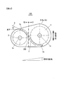
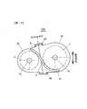
- FIG. 2 is a plan view of a gear-integrated electric motor 100.
- FIG. 2 is a side view of the gear-integrated electric motor 100.
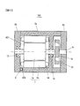
- FIG. 2 is a cross-sectional view taken along line AA of FIG. It is a figure which shows the housing main body 8a in which the groove
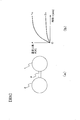
- FIG. 2 is a diagram illustrating a thermal relationship between a motor 1 and a gear mechanism 2 in the present embodiment. It is a figure which shows the case where the evaporation part 3e of the heat pipe 3 is made to contact the stator core end surface of the motor stator 1b.
- FIG. 6 is a diagram showing a gear-integrated motor 100 in which a motor housing 81 and a gear mechanism housing 82 are integrated by a fastener 80.
- FIG. 2 is a diagram showing a rear drive unit of a hybrid electric vehicle 1000 equipped with a gear-integrated electric motor 100.
- FIG. 1 is a plan view of the gear-integrated electric motor 100
- FIG. 2 is a side view of the gear-integrated electric motor 100. As shown in FIG.
- a gear-integrated electric motor 100 used for rear drive of a hybrid electric vehicle (HEV) 1000 will be described as an example.
- a rear axle 101 provided with a rear wheel 102 is connected to a gear shaft 2s of a gear-integrated electric motor 100 described later.
- the motor 1 of the gear-integrated electric motor 100 is driven and controlled by the inverter device 103 using the battery 104 as a power supply.
- the housing 8 of the present embodiment is constituted by a housing main body 8a in which a motor housing portion 801 and a gear mechanism housing portion 802 are formed, and an end bracket 8b covering the side surface of the housing main body 8a. Electric power is supplied to the motor 1 from a power supply unit (not shown), and when the gear mechanism 2 is driven by the motor 1, the gear shaft 2s which is an output shaft is rotationally driven. The gear shaft 2s applies a driving force to, for example, the rear axle of the vehicle. 1s is a motor shaft.
- the heat pipe 3 is provided on the housing body 8a.
- FIG. 3 is a cross-sectional view taken along the line AA of FIG.
- the motor housing portion 801 is provided with a motor 1.
- the motor stator 1 b to which the winding 10 is applied is fixed in a cylindrical motor housing portion 801 by press fitting or the like.
- a motor rotor 1a is rotatably disposed in the motor stator 1b.
- the motor shaft 1s of the motor rotor 1a is supported by bearings 12 provided on the housing body 8a and the end bracket 8b.
- the gear 11 fixed to the motor shaft 1 s meshes with a gear 22 provided in the gear mechanism 2.
- the gear mechanism 2 is provided with a plurality of gears.
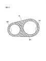
- FIG. 4 shows the heat pipe disposition side of the housing main body 8a.
- the housing main body 8a is formed with the motor housing portion 801 in which the motor 1 is provided and the gear mechanism housing portion 802 in which the gear mechanism 2 is provided.
- various structures such as ribs for disposing the motor 1 and the gear mechanism 2 are formed in the respective housing portions 801 and 802,
- FIG. 4 shows a schematic shape of the housing main body 8a, Their detailed structure has been omitted.
- a groove 803 for embedding the heat pipe 3 is formed on the side surface of the housing body 8a.
- the evaporator 3 e is disposed in the motor disposition area S 1 (near the motor 1) of the housing 8, and the condensation section 3 c is disposed in the gear mechanism disposition area S 2 (near the gear mechanism 2).
- a connection 300 which is arranged and connects them is provided so as to be arranged between the motor shaft 1s and the gear shaft 2s.
- the heat pipe 3 is a tubular container in which the working fluid is enclosed in a gas-liquid two-phase state, but the heat pipe 3 used in the present embodiment uses gravity to return the working fluid. A gravity heat pipe is used. Therefore, the heat pipe 3 is attached such that the condensation portion 3c is at a higher position than the evaporation portion 3e in the vertical direction of the gear integrated motor 100.
- the heat pipe 3 is fixed to the groove 803 by caulking, welding or soldering.
- a loop heat pipe As a heat pipe having no restriction on the positional relationship between the condenser 3c and the evaporator 3e, a loop heat pipe, a dream pipe (oscillating flow heat pipe), etc. are also known.
- the heat transport type per heat pipe cross-sectional area is much larger in the heat pipe type using gravity. Therefore, a gravity type heat pipe is suitable for HEVs and EVs that have severe restrictions on mounting space.
- FIG. 5 and 6 schematically show the thermal relationship between the motor 1 and the gear mechanism 2.
- FIG. 5 shows the case of a conventional gear-integrated motor
- FIG. 6 shows the case of the present embodiment. Indicates In the conventional gear-integrated motor shown in FIG. 5, since the heat pipe 3 is not provided, only the housing 8 thermally connects the motor 1 and the gear mechanism 2.
- the other parts except the motor housing part 801, the gear mechanism housing part 802 and the groove 803 are described as being filled with metal members, but in practice In order to reduce the weight, it is designed to make the thickness as thin as possible. Further, also in the region between the motor housing portion 801 and the gear mechanism housing portion 802, the weight is reduced by providing a cavity or the like.
- the conventional gear-integrated motor is structurally integrated by the housing 8, but no consideration is given to thermal integration for interlocking the temperatures of the motor 1 and the gear mechanism 2, The thermal resistance between the motor 1 and the gear mechanism 2 has not been reduced.
- FIG. 5 (a) the thermal structure of the housing 8 having such a structure is shown as the thermal structure 4. As shown in FIG. That is, the motor 1 and the gear mechanism 2 are thermally connected by the thermal structure 4.
- FIG. 5 (b) conceptually shows the temperature history of the gear-integrated motor shown in FIG. 5 (a). Since the thermal integration is insufficient and the thermal resistance of the thermal structure 4 is large, only the thermal capacity of the motor 1 alone contributes to the short-time load, as shown in FIG. 5 (b), the gear mechanism The temperature rise of 2 (curve 2c) is small, whereas the temperature rise of the motor 1 (curve 1c) is large.
- the motor 1 and the gear mechanism 2 are thermally connected by the heat pipe 3 in addition to the thermal structure 4,
- the thermal resistance between the motor 1 and the gear mechanism 2 is significantly reduced.
- part of the heat loss of the motor 1 is dissipated to the ambient air via the gearbox 2 side, and the temperature of the gear mechanism 2 is a curve 2c, as shown in FIG. 6 (b).
- the temperature of the motor 1 decreases from curve 1 c to curve 1 p as shown by curve 2 p. That is, since the heat capacity of the gear mechanism 2 can be utilized, the thermal time constant of the cooling system of the motor 1 can be increased, and the temperature rise of the motor 1 under a short time load can be suppressed.
- the evaporation portion 3e of the heat pipe 3 provided in the housing main body 8a may be brought into contact with the end face of the stator core of the motor stator 1b as shown in FIG. Thereby, heat transport from the motor 1 to the gear mechanism 2 can be performed more effectively.
- the evaporator 3e may be in direct thermal contact with the stator coil 10 as long as it is electrically and structurally acceptable.
- the motor 1 is disposed by disposing the evaporation portion 3e at or near the place where the oil 13 in the lower part of the motor 1 is stagnant. It is possible to eliminate that the temperature near the stagnation point of the oil 13 becomes relatively high compared to the others.
- the heat pipe 3 is provided in the housing main body 8a, but as shown in FIG. 8, the heat pipe 3 may be embedded in end brackets 8b provided on both side surfaces of the housing main body 8a.
- 8 (a) and 8 (b) are views showing the inner surface side of the end bracket 8b.
- the groove 804 is formed so as to avoid the region 1c facing the motor 1 and the region 2c facing the gear mechanism 2, and the heat pipe 3 is bent and embedded in the groove 804. I made it.
- a linear groove 805 is formed, and the linear heat pipe 3 is embedded in the groove 805.
- the heat pipe 3 does not interfere with the motor 1 and the gear mechanism 2 even if the heat pipe 3 faces the areas 1c and 2c indicated by the two-dot chain line, as shown in FIG. Placement is possible.
- the heat pipe 3 when the heat pipe 3 is provided on the end bracket 8b, the heat of the motor 1 is transmitted like the housing body 8a, the end bracket 8b, and the heat pipe 3.
- the oil when oil is enclosed in the housing 2 of the gear box 2 or the motor 1 for lubrication or cooling, the oil intrudes into the gap between the heat pipe 3 and the housing 8 or the end bracket 9, The effect of improving the thermal contact can be expected.
- a filler resin or the like having good thermal conductivity may be provided between the heat pipe 3 and the housing main body 8a or the motor stator 1b opposed to the heat pipe 3.
- the heat pipe 3 By embedding the heat pipe 3 in the end bracket 8b as shown in FIG. 8, the heat pipe 3 can be attached without almost increasing the external size of the geared electric motor 100, that is, the mounting volume. Further, by burying the heat pipe 3, the effect of suppressing the vibration of the heat pipe 3 can be expected as compared with the case where the heat pipe 3 is not embedded. Although the heat pipe 3 is embedded in the inner surface of the end bracket 8b in FIG. 8, it may be embedded in the outer surface side.
- the heat pipe 3 If the heat pipe 3 is broken, the internal working fluid may leak and become nonfunctional. Therefore, by burying the heat pipe 3 on the inner surface side of the end bracket 8b as shown in FIG. 8, the heat pipe 3 can be protected from flying objects such as stones by the end bracket 8b or the housing main body 8a. The effect of preventing the deterioration of the cooling performance can be obtained.
- the heat pipe 3 can be arrange
- a cavity 806 is formed between the motor accommodation portion 801 and the gear mechanism accommodation portion 802, and the heat pipe 3 is disposed in the cavity 806.
- the evaporator 3e of the heat pipe 3 is fixed to the wall 801a of the motor housing 801, and the condenser 3c is fixed to the wall 802a of the gear mechanism housing 802.
- the attachment posture of the heat pipe 3 is important.
- one of the bad road conditions where the driving force of the motor 1 is required is a steep slope, and the heat pipe 3 is predetermined even when the slope is steep. It is necessary to secure the heat transport performance of the That is, it is necessary to arrange the condensing part 3c to be positioned vertically above the evaporating part 3e when it is steeply inclined, and the condensing part 3c needs to be inclined so that the working fluid can be returned. is there.
- the angle ⁇ is an angle between the axial direction vector 6 of the condensation portion 3 c of the heat pipe 3 and the horizontal direction. If the angle ⁇ is larger than the inclination angle required for the vehicle on which the gear integrated electric motor 100 is mounted, the angle in the extending direction of the heat pipe 3 (the angle with respect to the horizontal direction) becomes larger than the maximum inclination angle.
- the heat transport performance of the heat pipe 3 can be secured. For example, when the gradient required for the vehicle is 20%, the heat pipe 3 may be disposed so that the angle ⁇ is 11.3 degrees or more.
- the heat pipe 3 using the working fluid when the temperature of the working fluid becomes lower than the melting point, it solidifies, and there arises a problem that the circulation of the working fluid and the heat transport of the heat pipe 3 can not be performed.
- the problem of freezing occurs at temperatures lower than 0 ° C.
- one of the bad road conditions under which the driving force of the motor 1 for HEV or EV is required is a condition of traveling on a slippery road surface such as a snowy road or an ice burn at low temperature. Even when used under such a low temperature condition, the heat pipe 3 needs to exhibit a predetermined heat transport performance.
- FIG. 10 shows the inner surface side (the side facing the housing 8a) of the end plate 8b, and a plurality of heat pipes 3L, 3S are provided on the inner surface of the end plate 8b.
- FIG. 11 is a view showing the shape of the heat pipe 3S.
- the heat pipe 3L also has the same shape as the heat pipe 3S.
- the heat pipe 3S is bent in a U-shape, and the connection portion 300 substantially parallel to the end face of the housing body 8a is embedded on the inner surface side of the end plate 8b (not shown) (see FIG. 10).
- One end including the evaporation portion 3e of the heat pipe 3S and the other end including the condensation portion 3c are bent in the direction of the housing main body 8a with respect to the connection portion 300 and embedded in the housing main body 8a There is.
- the heat pipe 3 is bent in a U-shape, and the method of embedding the condensing part 3c and the evaporating part 3e in the thickness direction of the housing body 8a (axial direction of the motor 1) is shown in FIG.
- the present invention can also be applied to the configuration shown in FIG. 2 and the configuration shown in FIG.
- the whole of the evaporating part 3e is disposed close to the motor 1 which is a heat generating part, and the whole of the condensing part 3c is Can be brought close to the gear mechanism 2.
- the condensation portion 3c of the heat pipe 3S is disposed in a region relatively close to the motor 1 (a region C on the left side of an alternate long and short dash line in FIG. 10) of the housing body 8a.
- the condensation part 3c of the heat pipe 3L is disposed in an area (area D on the right side of the dashed dotted line in FIG. 10) farther from the motor 1 than in the case of the heat pipe 3S.
- two types of heat pipes 3L and 3S are provided regarding the arrangement form.
- the heat pipes 3L and 3S are frozen at a low temperature.
- the condensation part 3c of the heat pipe 3S relatively close to the motor 1 becomes high temperature due to heat generation of the motor 1, and exceeds the melting point of the working fluid.
- the heat pipe 3S functions to transfer the heat of the motor 1 to the gear mechanism 2 side.
- the outside temperature at this time is low, the temperature difference between the motor stator 1b, the motor rotor 1a and the gear mechanism 2 is large, and the cooling performance is sufficient only with the heat pipe 3S having the condensing portion 3c on the side close to the motor 1. You can get it.
- the heat unit 3 As described above, in the present embodiment, as a means for securing the performance of the heat pipe 3 at low temperature, the heat unit 3 has the heat pipe 3S close to the motor 1 and the heat unit 3c disposed far from the motor 1 Two types of heat pipes with the pipe 3L were provided. As a result, even when the temperature is low, the heat pipe 3S functions immediately after the start of the motor, and as the temperature of the gear mechanism 2 thereby rises, the heat pipe 3L having a higher heat transport capacity comes to function.
- a heat pipe 3 whose working fluid has a melting point lower than ambient temperature (freezing point) such as a fluorine-based inert refrigerant is used.
- a variable conductance heat pipe is used that is filled with an inert non-condensable gas, such as helium, along with the working fluid water.
- the heat transport amount of the heat pipe 3 is allowed to decrease, and the melting point is within the operating temperature range.
- the heat pipes containing the working fluid of melting point a, melting point b, melting point c, ... may be used in combination.
- the motor 1 and the gear mechanism 2 are housed in the common housing main body 8a, but as shown in FIG. 12, they may be housed in different housings.
- the motor 1 is housed in a motor housing 81
- the gear mechanism 2 is housed in a gear mechanism housing 82.
- the motor housing 81 and the gear mechanism housing 82 are integrated by the fastener 80.
- the heat pipe 3 is embedded on the outer peripheral side of the motor housing 81 and the gear mechanism housing 82. Even with such a structure, the same cooling performance improvement effect as that of the above embodiment can be obtained.
- the heat pipe 3 when the heat pipe 3 is frozen or damaged, or when the working fluid condensate can not return, a predetermined amount of heat transport can not be secured.
- the heat pipe 3 has a characteristic that the amount of reflux falls below the amount of evaporation when it exceeds a certain amount of heat transport, making it impossible to transport heat.
- the temperature in the motor 1 is monitored by a thermistor or the like, it is possible to detect a temperature abnormality. Further, when temperature abnormality is detected, overheat of the motor 1 can be avoided by reducing the output of the motor 1 for control.
- the heat pipe 3 is disposed between the gear mechanism 2 and the motor 1, the evaporator 3e of the heat pipe 3 is on the motor side, the condenser 3c is on the gear mechanism 2 side, and the condenser 3c is the evaporator.
- the motor shaft 1s and the gear shaft 2s are parallel to each other
- the motor shaft 1s and the gear shaft 2s are similarly applicable to a gear-integrated electric motor having a configuration in which the motor 1 and the gear mechanism 2 are disposed such that the direction is the same.
Landscapes
- Engineering & Computer Science (AREA)
- Power Engineering (AREA)
- Motor Or Generator Cooling System (AREA)
- Connection Of Motors, Electrical Generators, Mechanical Devices, And The Like (AREA)
Abstract
ギア一体型電動モータは、電気入力により駆動力を発生するモータ(1)と、モータの駆動力を変換するギア機構(2)と、モータおよびギア機構を内包するハウジング(8)とを備え、モータ軸(1s)およびギア出力軸(2s)がほぼ水平となる水平姿勢で使用され、ハウジングのモータ配置領域に配置された蒸発部(3e)と、水平姿勢における鉛直方向に関して蒸発部よりも上側であってハウジングのギア機構配置領域に配置された凝縮部(3c)とを有するヒートパイプ(3)を、少なくとも一つ備える。
Description
本発明は、ギア機構とモータ本体とがハウジング内に内包されたギア一体型電動モータ、および、そのギア一体型電動モータを搭載する電気車に関する。
ハイブリッド電気自動車(HEV)や電気自動車(EV)、さらには電気鉄道車両のような移動体の駆動源として電動モータを利用する場合には、小型・軽量と高出力を両立させなければならない。一般的にモータの体格とモータの冷却性能には密接な関係があり、同一体格でも冷却性能を向上させることにより、より高い出力を得ることが可能である。このため、冷却性能を向上させるべく、フィンを設けたり、ファンとポンプからなる専用の冷却系を付加したり、放熱面積拡大のための様々な工夫が積み重ねられてきた。
例えば、特許文献1では、ヒートパイプと放熱器からなる冷却系を付加する例が挙げられている。モータと放熱器とをヒートパイプで接続し、ヒートパイプを介して放熱器に熱輸送した熱を、放熱器から空気中に放熱するようにしている。
しかしながら、HEVやEV等では、単に冷却面積を増やすだけでは不十分な場合が出てきた。追加した放熱器が機能するためには、熱が放熱器まで伝わる必要があるが、HEVやEVでは短時間の間欠動作が前提となるため、熱が放熱器に伝わる前にモータの温度が上昇し、許容値に達してしまう可能性がある。
このような状況を回避するためには、例えば、モータ自身の熱容量を大きくすればよいが、モータの重量増加を伴い、燃費の悪化を招くという問題が生じる。特許文献1のようにヒートパイプと放熱器とを用いる構成においても、モータ損失に見合った放熱面積の放熱器が必要であり、重量増加を避けられない。
本発明の第1の態様によると、ギア一体型電動モータは、電気入力により駆動力を発生するモータと、モータの駆動力を変換するギア機構と、モータおよびギア機構を内包するハウジングとを備え、モータ軸およびギア出力軸がほぼ水平となる水平姿勢で使用され、ハウジングのモータ配置領域に配置された蒸発部と、水平姿勢における鉛直方向に関して蒸発部よりも上側であってハウジングのギア機構配置領域に配置された凝縮部とを有するヒートパイプを、少なくとも一つ備える。
本発明の第2の態様によると、第1の態様のギア一体型電動モータにおいて、ヒートパイプを、ハウジングの部材内に埋設するのが好ましい。
本発明の第3の態様によると、第1の態様のギア一体型電動モータにおいて、ヒートパイプの蒸発部と凝縮部との間の接続部を、モータ軸とギア出力軸との間に配置するのが好ましい。
本発明の第4の態様によると、第1の態様のギア一体型電動モータにおいて、ハウジングのモータ配置領域には潤滑油などのオイルが内包され、蒸発部をオイルの滞留部またはその近傍に配置するのが好ましい。
本発明の第5の態様によると、第1の態様のギア一体型電動モータにおいて、蒸発部の少なくとも一部を、モータのステータ部に接触させるのが好ましい。
本発明の第6の態様によると、第1の態様のギア一体型電動モータにおいて、ヒートパイプを複数備え、複数のヒートパイプは、ギア機構配置領域であってモータに近接する第1の領域に凝縮部が配置された第1のヒートパイプと、ギア機構配置領域であって第1の領域よりもモータから離れている第2の領域に凝縮部が配置された第2のヒートパイプと、で構成されるのが好ましい。
本発明の第7の態様によると、第1の態様のギア一体型電動モータにおいて、ヒートパイプの凝縮部を含む部分、およびヒートパイプの蒸発部を含む部分を、それぞれモータ軸に対して平行となるようにハウジング部材内に埋設するのが好ましい。
本発明の第8の態様によると、電気車は、第1の態様のギア一体型電動モータが水平姿勢で搭載され、ギア一体型電動モータのギア出力軸からの駆動力により車両走行を行わせる走行機構を備える。
本発明の第9の態様によると、第8の態様の電気車において、水平方向に対するヒートパイプの延在方向の角度を、電気車に要求される最大勾配角よりも大きく設定するのが好ましい。
本発明によれば、重量増加を抑えつつモータの冷却性能を向上させることができる。
以下、図を参照して本発明を実施するための形態について説明する。尚、以下においては、主にハイブリッド電気自動車(HEV)用のモータに本発明を適用した場合について説明するが、本発明の適用はこれに限られるものでない。
-第1の実施の形態-
図1~4は本発明によるギア一体型電動モータの第1の実施の形態を示す図である。図1はギア一体型電動モータ100の平面図であり、図2はギア一体型電動モータ100の側面図である。
図1~4は本発明によるギア一体型電動モータの第1の実施の形態を示す図である。図1はギア一体型電動モータ100の平面図であり、図2はギア一体型電動モータ100の側面図である。
なお、以下では、図13に示すように、ハイブリッド電気自動車(HEV)1000のリア駆動に用いられるギア一体型電動モータ100を例に説明する。リア車輪102が設けられたリア車軸101は、後述するギア一体型電動モータ100のギア軸2sに接続されている。ギア一体型電動モータ100のモータ1は、バッテリ104を電源としてインバータ装置103により駆動制御される。
図2に示すように、ギア一体型電動モータ100においては、モータ1とギア機構2とはハウジング8に内包されている。本実施の形態のハウジング8は、モータ収容部801とギア機構収容部802とが形成されたハウジング本体8aと、ハウジング本体8aの側面を覆うエンドブラケット8bとで構成されている。モータ1には不図示の電源部から電力が供給され、モータ1によりギア機構2を駆動すると、出力軸であるギア軸2sが回転駆動される。ギア軸2sは、例えば車両のリア側車軸に駆動力を与える。1sはモータ軸である。ハウジング本体8aにはヒートパイプ3が設けられている。
図3は、図1のA-A断面を示す図である。モータ収容部801にはモータ1が設けられている。巻き線10が施されたモータステータ1bは、円筒状のモータ収容部801内に圧入等により固定されている。モータステータ1bの内部には、モータロータ1aが回転可能に配置されている。モータロータ1aのモータ軸1sは、ハウジング本体8aおよびエンドブラケット8bに設けられた軸受12によって支持されている。モータ軸1sに固定されたギア11は、ギア機構2に設けられたギア22と噛合している。ギア機構2には複数のギアが設けられている。
図4は、ハウジング本体8aのヒートパイプ配設側を示したものである。ハウジング本体8aには上述したように、モータ1が設けられるモータ収容部801と、ギア機構2が設けられるギア機構収容部802とが形成されている。なお、各収容部801,802にはモータ1およびギア機構2を配置するためのリブなど各種の構造体が形成されているが、図4はハウジング本体8aの概略形状を示したものであり、それらの詳細構造は省略した。ハウジング本体8aの側面には、ヒートパイプ3を埋め込むための溝803が形成されている。
図2に示すように、ヒートパイプ3は、蒸発部3eがハウジング8のモータ配置領域S1(モータ1の近傍)に配置され、凝縮部3cがギア機構配置領域S2(ギア機構2の近傍)に配置され、それらを繋ぐ接続部300がモータ軸1sとギア軸2sとの間に配置されるように設けられている。ヒートパイプ3は管状の容器の中に作動流体を気液二相状態として封入したものであるが、本実施の形態で用いられているヒートパイプ3には、重力を利用して作動流体を還流させる重力式のヒートパイプが用いられている。そのため、ギア一体型モータ100の鉛直方向に関して、凝縮部3cが蒸発部3eよりも高い位置となるようにヒートパイプ3は取り付けられている。ヒートパイプ3は、カシメ、溶接もしくは半田付け等により溝803に固定される。
ヒートパイプ3の一端を加熱し、他端を冷却すると、加熱側(蒸発部3e)で作動流体の蒸発が起こり、蒸気が冷却側に到達し、冷却側(凝縮部3c)で凝縮、凝縮液が容器の壁面を伝って再び加熱側(蒸発部3e)に戻る。この作動流体の循環および相変化を繰り返すことにより、蒸発部3eから凝縮部3cへ熱を輸送する。凝縮液が蒸発部3eへと還流する際に重力を利用するため、蒸発部3eを凝縮部3cより下方としている。
一般的には、凝縮部3cと蒸発部3eの位置関係に制約がないヒートパイプとして、ループヒートパイプやドリームパイプ(振動流型ヒートパイプ)なども知られている。しかし、これらのヒートパイプに比べ、重力を利用するタイプのヒートパイプの方がヒートパイプ断面積あたりの熱輸送量は大幅に大きい。そのため、実装スペースに厳しい制約があるHEVやEV用としては、重力式のヒートパイプが好適である。もちろん、ループヒートパイプやドリームパイプを使用しても構わない。
図5,6はモータ1とギア機構2との熱的な関係を模式的に示したものであり、図5は従来のギア一体型モータの場合を示し、図6は本実施の形態の場合を示す。図5に示す従来のギア一体型モータでは、ヒートパイプ3が設けられていないので、モータ1とギア機構2とを熱的に接続するものは,ハウジング8によってのみとなっている。
図4に示したハウジング本体8aの概略図では、モータ収容部801,ギア機構収容部802および溝803を除くその他の部分は金属部材で満たされているように記載されているが、実際には、軽量化を図るべく肉厚をなるべく薄くするように設計されている。また、モータ収容部801とギア機構収容部802との間の領域においても、空洞を設けるなどして軽量化を図っている。
このように、従来のギア一体型モータでは、ハウジング8によって構造的には一体化されているが、モータ1とギア機構2との温度を連動させる熱的一体化の配慮がなされておらず、モータ1とギア機構2との間の熱抵抗の低減が図れていなかった。図5(a)では、そのような構造のハウジング8の熱的な構造を熱的構造体4で示した。すなわち、モータ1とギア機構2とは、熱的構造体4によって熱的に接続されていることになる。
図5(b)は、図5(a)に示すギア一体型モータの温度履歴を概念的に示したものである。熱的な一体化が不充分で熱的構造体4の熱抵抗が大きいため、短時間負荷に対してはモータ1単独の熱容量しか寄与せず、図5(b)に示すように、ギア機構2の温度上昇(曲線2c)は小さく、それに対してモータ1の温度上昇(曲線1c)は大きくなる。
一方、本実施の形態の場合には、図6(a)に示すように、熱的構造体4に加えて、ヒートパイプ3によってモータ1とギア機構2とが熱的に接続されており、図5(a)に対してモータ1とギア機構2との間の熱抵抗が大幅に低減される構造としている。このような構造とすることにより、モータ1の熱損失の一部がギアボックス2側を経由して周囲空気に放散され、図6(b)に示すように、ギア機構2の温度は曲線2cから曲線2pのように上昇し、モータ1の温度は曲線1cから曲線1pのように低下する。すなわち、ギア機構2の熱容量を活用できるので、モータ1の冷却系の熱時定数を増やすことができ、短時間負荷時におけるモータ1の温度上昇を抑えることができる。
さらに、ヒートパイプ3を追加するだけで、特許文献1の構成のように放熱器を別に設ける必要がないので、重量増加を抑えることができる。なお、図2や図4に示すようにハウジング8に埋設されている場合には、逆に、溝の部分のハウジング部材より軽くなる場合もある。
なお、ハウジング本体8aに設けられたヒートパイプ3の蒸発部3eを、図7に示すようにモータステータ1bのステータコア端面に接触させるようにしても良い。それにより、モータ1からギア機構2への熱輸送をより効果的に行うことができる。もちろん電気的、構造的に許容されるのであれば、蒸発部3eをステータコイル10に直接熱接触させても構わない。また、ギアボックス2あるいはモータ1のハウジング8内にオイル13が封入されている場合、モータ1下部のオイル13が滞留している場所またはその近くに蒸発部3eを配置することにより、モータ1においてオイル13の滞留箇所付近の温度が他に比べ、比較的高温になることを解消することができる。
(変形例)
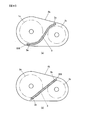
上述した実施の形態では、ハウジング本体8aにヒートパイプ3を設けたが、図8に示すように、ハウジング本体8aの両側面に設けられたエンドブラケット8bに埋設するようにしても良い。図8(a),(b)はエンドブラケット8bの内面側を示す図である。図8(a)に示す例では、モータ1に対向する領域1cおよびギア機構2に対向する領域2cを避けるように溝804を形成し、その溝804内にヒートパイプ3を曲げて埋設するようにした。
上述した実施の形態では、ハウジング本体8aにヒートパイプ3を設けたが、図8に示すように、ハウジング本体8aの両側面に設けられたエンドブラケット8bに埋設するようにしても良い。図8(a),(b)はエンドブラケット8bの内面側を示す図である。図8(a)に示す例では、モータ1に対向する領域1cおよびギア機構2に対向する領域2cを避けるように溝804を形成し、その溝804内にヒートパイプ3を曲げて埋設するようにした。
一方、図8(b)に示す例では、直線的な溝805を形成し、その溝805内に直線状のヒートパイプ3を埋設するようにした。エンドブラケット8bに埋設する場合、ヒートパイプ3が二点鎖線で示す領域1c、2cに対向していても、モータ1およびギア機構2と干渉することがないので、図8(b)のような配置が可能である。
このようにエンドブラケット8bにヒートパイプ3を設けた場合、モータ1の熱は、ハウジング本体8a、エンドブラケット8b、ヒートパイプ3のように伝達される。ただし、潤滑あるいは冷却のために、ギアボックス2あるいはモータ1のハウジング8内にオイルが封入されている場合には、オイルが、ヒートパイプ3とハウジング8もしくはエンドブラケット9の隙間に侵入し、両者の熱接触を向上させる効果が期待できる。また、ヒートパイプ3と対向するハウジング本体8aまたはモータステータ1bとの間に、熱伝導性の良い充填物(樹脂等)を設けるようにしても良い。
図8のようにヒートパイプ3をエンドブラケット8bに埋設する構造とすることにより、ギア一体型電動モータ100の外形サイズ、つまり実装容積をほとんど増やすことなくヒートパイプ3を付設することができる。また、ヒートパイプ3を埋設する構造とすることにより、埋設しない場合に比べ、ヒートパイプ3の振動を抑制する効果も期待できる。なお、図8では、ヒートパイプ3をエンドブラケット8bの内側の面に埋設したが、外面側に埋設してもよい。
なお、ヒートパイプ3が破損すると、内部の作動流体が漏れて機能しなくなる恐れがある。したがって、図8のようにエンドブラケット8bの内面側にヒートパイプ3を埋設する構造とすることにより、エンドブラケット8bもしくはハウジング本体8aによって、石などの飛来物からヒートパイプ3を保護することができ、冷却性能の低下を防止する効果を得ることができる。
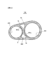
ところで、ハウジング本体8aの構造が図9に示すように形状の場合、ハウジング本体8aの端面ではなく、内部領域にもヒートパイプ3を配置することができる。図9に示す例では、モータ収容部801とギア機構収容部802との間に空洞806が形成されており、ヒートパイプ3はその空洞806内に配置されている。そして、ヒートパイプ3の蒸発部3eはモータ収容部801の壁部801aに固定され、凝縮部3cはギア機構収容部802の壁部802aに固定されている。
上述したように、ヒートパイプ3の作動流体の還流時には重力を利用するため、ハウジング8にヒートパイプ3を取り付ける場合には、ヒートパイプ3の取り付け姿勢が重要となる。特に、車両搭載のギア一体型電動モータの場合、モータ1の駆動力が要求される悪路条件の一つに急勾配の登板が挙げられ、急勾配で傾斜した際にもヒートパイプ3が所定の熱輸送性能を確保する必要がある。すなわち、急勾配で傾斜した際に、凝縮部3cが蒸発部3eよりも鉛直上方に位置するような配置とするとともに、作動流体の還流が可能なように凝縮部3cが傾斜している必要がある。
上述した図2において、角度θは、ヒートパイプ3の凝縮部3cの軸方向ベクトル6と水平方向との成す角度である。この角度θが、ギア一体型電動モータ100が搭載される車両に要求される勾配角よりも大きければ、ヒートパイプ3の延在方向の角度(水平方向に対する角度)が最大勾配角よりも大きくなり、ヒートパイプ3の熱輸送性能を確保することができる。例えば、車両に要求される勾配が20%の場合、角度θが11.3度以上となるようにヒートパイプ3を配置すればよい。
図10,11は本発明の第2の実施の形態を示す図である。作動流体を用いるヒートパイプ3においては、作動流体の温度が融点以下になると凝固してしまい、作動流体の循環ひいてはヒートパイプ3の熱輸送ができなくなる問題が発生する。例えば、潜熱が大きいということから作動流体として一般的に用いられる水の場合は、0℃以下になると凍結の問題が発生する。一方、HEVもしくはEV用のモータ1の駆動力が要求される悪路条件の一つに、雪道やアイスバーンなど低温時にすべりやすい路面を走行する条件が挙げられる。このような低温状況下で使用された場合においても、ヒートパイプ3は所定の熱輸送性能を発揮する必要がある。
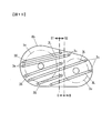
そこで、第2の実施の形態では、図10,11のような構成を採用することで、低温時のヒートパイプ3の性能を確保できるようにした。図10はエンドプレート8bの内表面側(ハウジング8aに対向する側)を示したものであり、エンドプレート8bの内表面には、複数のヒートパイプ3L,3Sが設けられている。
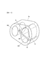
図11は、ヒートパイプ3Sの形状を示す図である。なお、図示は省略したが、ヒートパイプ3Lもヒートパイプ3Sと同様の形状をしている。ヒートパイプ3Sはコの字形状に折れ曲がっており、ハウジング本体8aに端面にほぼ平行な接続部300は、図示しないエンドプレート8bの内表面側に埋設されている(図10参照)。ヒートパイプ3Sの蒸発部3eを含む一方の端部、および、凝縮部3cを含む他方の端部は、接続部300に対してハウジング本体8a方向に折れ曲がっていて、ハウジング本体8a内に埋設されている。
なお、図11に示すようにヒートパイプ3をコの字形状に屈曲させて、凝縮部3cおよび蒸発部3eをハウジング本体8aの厚さ方向(モータ1の軸方向)に埋設する方法は、図2に示す構成や、図4に示すような構成に対しても適用することができる。このように、凝縮部3cおよび蒸発部3eをハウジング本体8aの厚さ方向に埋設することで、蒸発部3eの全体を発熱部であるモータ1に近接して配置するとともに、凝縮部3cの全体をギア機構2に近接させることができる。
ヒートパイプ3Sの凝縮部3cは、ハウジング本体8aの比較的にモータ1に近い領域(図10の一点鎖線の左側の領域C)に配置されている。一方、ヒートパイプ3Lの凝縮部3cは、モータ1に対してヒートパイプ3Sの場合よりも遠くに離れた領域(図10の一点鎖線の右側の領域D)に配置されている。このように、図10に示した例では、配置形態に関して2つの種類のヒートパイプ3L,3Sを備えるようにした。
このような構成で、低温時においてヒートパイプ3L,3Sが凍結している場合を考える。モータ1が駆動開始されると、まず、モータ1に比較的近いヒートパイプ3Sの凝縮部3cがモータ1の発熱により高温になり、作動流体の融点を超える。その結果、ヒートパイプ3Sが機能して、モータ1の熱をギア機構2側に伝達される。また、このときの外気温が低いことから、モータステータ1b、モータロータ1aとギア機構2との温度差が大きく、モータ1に近い側に凝縮部3cがあるヒートパイプ3Sのみで十分な冷却性能を得ることができる。
さらに、モータ1の負荷が続き、ギア機構2側が温められてくると、モータ1から遠い側に凝縮部3cがあるヒートパイプ3Lの作動流体が次第に融解され、ついには、全てのヒートパイプ3L,3Sが機能するようになる。両方のヒートパイプ3L,3Sが機能するようになった場合、ヒートパイプ3Lの方が両端の温度差が大きいので、熱輸送量が飛躍的に増加する。
このように、本実施の形態では、低温時のヒートパイプ3の性能を確保する手段として、凝縮部3cがモータ1に近いヒートパイプ3Sと、凝縮部3cをモータ1から遠く離して配置したヒートパイプ3Lとの2種類のヒートパイプを設けるようにした。それにより、低温時であってもモータ起動直後からヒートパイプ3Sが機能し、それによるギア機構2の温度上昇につれて、より熱輸送能力の高いヒートパイプ3Lが機能するようになる。
なお、図10,11のように凝縮部3cの配置形態を異ならせる代わりに、ヒートパイプ3内の作動流体の成分を変えることにより、図10,11に示す実施形態と同様の作用効果を得ることもできる。例えば、フッ素系不活性冷媒のような融点が周囲温度(氷点)よりも低いものを作動流体としたヒートパイプ3を使用する。あるいは、作動流体の水と一緒に、不活性かつ動作温度範囲で非凝縮性の気体、例えばヘリウムを封入した可変コンダクタンスヒートパイプを使用する。また、外気温が低い場合にはモータロータ1aとモータステータ1bとの許容温度差が大きくなることから、ヒートパイプ3の熱輸送量が小さくなることを許容して、動作温度範囲内に融点がある、融点a、融点b、融点c、…の作動流体をおのおの封入したヒートパイプを、組み合わせて使用するようにしても良い。
なお、上述した実施の形態では、共通のハウジング本体8a内にモータ1とギア機構2を収納するようにしたが、図12に示すように、別々のハウジングに収納するようにしても良い。図12に示す例では、モータ1はモータハウジング81に収納され、ギア機構2はギア機構ハウジング82内に収納されている。モータハウジング81とギア機構ハウジング82とは締結具80によって一体化される。ヒートパイプ3は、モータハウジング81およびギア機構ハウジング82の外周側に埋設されている。このような構造であっても、上記実施の形態と同様の冷却性能向上効果を得ることができる。
ところで、先述のように、ヒートパイプ3が凍結したり破損したりした場合や、作動流体の凝縮液が還流できないような姿勢になった場合には、所定の熱輸送量が確保できなくなる。また、ヒートパイプ3にはある熱輸送量を超えると還流量が蒸発量を下回り、熱輸送できなくなるという特性がある。これらの場合については、モータ1内の温度をサーミスタなどでモニタすれば、温度異常により検知することが可能である。また、温度異常を検知した場合には、制御上モータ1の出力を低減させることによりモータ1の過熱を回避できる。
また、上記実施の形態においては、電気車の一種であるハイブリッド電気自動車(HEV)用のモータについて説明したが、他の電気車、例えば電気自動車や電気鉄道車両、電動建設機械や、ギア一体型電動モータを備える産業機械についても、同様に適用可能である。いずれの場合においても、ギア機構2とモータ1との間にヒートパイプ3を、ヒートパイプ3の蒸発部3eがモータ側、凝縮部3cがギア機構2側であって、凝縮部3cが蒸発部3eより上方となるように配置することにより、上述の実施の形態と同様の作用効果を得ることができる。なお、上述した実施の形態では、モータ軸1sとギア軸2sとが互いに平行となるようにモータ1とギア機構2とが配置される場合を例に説明したが、モータ軸1sとギア軸2sとが同一方向を向くようにモータ1とギア機構2とが配置される構成のギア一体型電動モータにも、本発明は同様に適用できる。
上述した各実施形態はそれぞれ単独に、あるいは組み合わせて用いても良い。それぞれの実施形態での効果を単独あるいは相乗して奏することができるからである。また、本発明の特徴を損なわない限り、本発明は上記実施の形態に何ら限定されるものではない。
上記では、種々の実施の形態および変形例を説明したが、本発明はこれらの内容に限定されるものではない。本発明の技術的思想の範囲内で考えられるその他の態様も本発明の範囲内に含まれる。
次の優先権基礎出願の開示内容は引用文としてここに組み込まれる。
日本国特許出願2010年第85120号(2010年4月1日出願)
日本国特許出願2010年第85120号(2010年4月1日出願)
Claims (9)
- 電気入力により駆動力を発生するモータと、前記モータの駆動力を変換するギア機構と、前記モータおよび前記ギア機構を内包するハウジングとを備え、モータ軸およびギア出力軸がほぼ水平となる水平姿勢で使用されるギア一体型電動モータであって、
前記ハウジングのモータ配置領域に配置された蒸発部と、前記水平姿勢における鉛直方向に関して前記蒸発部よりも上側であって前記ハウジングのギア機構配置領域に配置された凝縮部とを有するヒートパイプを、少なくとも一つ備えたギア一体型電動モータ。 - 請求項1に記載のギア一体型電動モータにおいて、
前記ヒートパイプを、前記ハウジングの部材内に埋設したギア一体型電動モータ。 - 請求項1に記載のギア一体型電動モータにおいて、
前記ヒートパイプの前記蒸発部と前記凝縮部との間の接続部を、前記モータ軸と前記ギア出力軸との間に配置したギア一体型電動モータ。 - 請求項1に記載のギア一体型電動モータにおいて、
前記ハウジングのモータ配置領域には潤滑油などのオイルが内包され、前記蒸発部を前記オイルの滞留部またはその近傍に配置したギア一体型電動モータ。 - 請求項1に記載のギア一体型電動モータにおいて、
前記蒸発部の少なくとも一部を、前記モータのステータ部に接触させたギア一体型電動モータ。 - 請求項1に記載のギア一体型電動モータにおいて、
前記ヒートパイプを複数備え、
前記複数のヒートパイプは、前記ギア機構配置領域であって前記モータに近接する第1の領域に前記凝縮部が配置された第1のヒートパイプと、前記ギア機構配置領域であって前記第1の領域よりも前記モータから離れている第2の領域に前記凝縮部が配置された第2のヒートパイプと、で構成されるギア一体型電動モータ。 - 請求項1に記載のギア一体型電動モータにおいて、
前記ヒートパイプの前記凝縮部を含む部分、および前記ヒートパイプの前記蒸発部を含む部分を、それぞれモータ軸に対して平行となるように前記ハウジング部材内に埋設したギア一体型電動モータ。 - 請求項1に記載のギア一体型電動モータが前記水平姿勢で搭載され、
前記ギア一体型電動モータの前記ギア出力軸からの駆動力により車両走行を行わせる走行機構を備えた電気車。 - 請求項8に記載の電気車において、
水平方向に対する前記ヒートパイプの延在方向の角度を、電気車に要求される最大勾配角よりも大きく設定した電気車。
Priority Applications (1)
| Application Number | Priority Date | Filing Date | Title |
|---|---|---|---|
| US13/638,406 US9059607B2 (en) | 2010-04-01 | 2011-03-31 | Gear-integrated electric motor and electric vehicle |
Applications Claiming Priority (2)
| Application Number | Priority Date | Filing Date | Title |
|---|---|---|---|
| JP2010085120A JP5538035B2 (ja) | 2010-04-01 | 2010-04-01 | ギア一体型電動モータ |
| JP2010-085120 | 2010-04-01 |
Publications (1)
| Publication Number | Publication Date |
|---|---|
| WO2011125864A1 true WO2011125864A1 (ja) | 2011-10-13 |
Family
ID=44762802
Family Applications (1)
| Application Number | Title | Priority Date | Filing Date |
|---|---|---|---|
| PCT/JP2011/058273 Ceased WO2011125864A1 (ja) | 2010-04-01 | 2011-03-31 | ギア一体型電動モータおよび電気車 |
Country Status (3)
| Country | Link |
|---|---|
| US (1) | US9059607B2 (ja) |
| JP (1) | JP5538035B2 (ja) |
| WO (1) | WO2011125864A1 (ja) |
Families Citing this family (9)
| Publication number | Priority date | Publication date | Assignee | Title |
|---|---|---|---|---|
| US9695927B2 (en) * | 2009-07-30 | 2017-07-04 | Bison Gear & Engineering Corp. | Motor-gearbox assembly |
| US9750160B2 (en) * | 2016-01-20 | 2017-08-29 | Raytheon Company | Multi-level oscillating heat pipe implementation in an electronic circuit card module |
| JP6822282B2 (ja) * | 2017-03-31 | 2021-01-27 | 日本電産トーソク株式会社 | 電動アクチュエータ |
| JP2020048332A (ja) * | 2018-09-19 | 2020-03-26 | トヨタ自動車株式会社 | 電動機システム |
| DE102018219837B4 (de) * | 2018-11-20 | 2020-10-29 | Audi Ag | System mit einer Elektromaschine und einem Getriebe |
| FR3091916B1 (fr) | 2019-01-18 | 2021-05-28 | Ge Energy Power Conversion Technology Ltd | Système d’entraînement mécanique et motocompresseur associé |
| JP7387498B2 (ja) * | 2020-03-12 | 2023-11-28 | 住友重機械工業株式会社 | ギヤモータ |
| US12620874B2 (en) | 2023-10-06 | 2026-05-05 | GM Global Technology Operations LLC | Winding slot-embedded vapor chambers and heat pipes with endcap heat sinks for electric machines |
| US12592619B2 (en) | 2023-10-25 | 2026-03-31 | GM Global Technology Operations LLC | Rotor shaft-mounted vapor chambers and heat pipes with endcap heat sinks for electric machines |
Citations (3)
| Publication number | Priority date | Publication date | Assignee | Title |
|---|---|---|---|---|
| JP2004050990A (ja) * | 2002-07-22 | 2004-02-19 | Railway Technical Res Inst | 電気車 |
| JP2005130554A (ja) * | 2003-10-21 | 2005-05-19 | Nissan Motor Co Ltd | 回転電機の抜熱構造と回転電機の製造方法 |
| JP2008125172A (ja) * | 2006-11-09 | 2008-05-29 | Toshiba Corp | 車両用駆動装置 |
Family Cites Families (3)
| Publication number | Priority date | Publication date | Assignee | Title |
|---|---|---|---|---|
| US6129193A (en) * | 1997-08-29 | 2000-10-10 | American Cooling Systems, L.L.C. | Electric fan clutch |
| JP2008072881A (ja) * | 2006-09-15 | 2008-03-27 | Toyota Motor Corp | モータ |
| KR101238209B1 (ko) * | 2010-11-29 | 2013-03-04 | 엘지전자 주식회사 | 전동기 |
-
2010
- 2010-04-01 JP JP2010085120A patent/JP5538035B2/ja active Active
-
2011
- 2011-03-31 US US13/638,406 patent/US9059607B2/en active Active
- 2011-03-31 WO PCT/JP2011/058273 patent/WO2011125864A1/ja not_active Ceased
Patent Citations (3)
| Publication number | Priority date | Publication date | Assignee | Title |
|---|---|---|---|---|
| JP2004050990A (ja) * | 2002-07-22 | 2004-02-19 | Railway Technical Res Inst | 電気車 |
| JP2005130554A (ja) * | 2003-10-21 | 2005-05-19 | Nissan Motor Co Ltd | 回転電機の抜熱構造と回転電機の製造方法 |
| JP2008125172A (ja) * | 2006-11-09 | 2008-05-29 | Toshiba Corp | 車両用駆動装置 |
Also Published As
| Publication number | Publication date |
|---|---|
| JP5538035B2 (ja) | 2014-07-02 |
| US20130049497A1 (en) | 2013-02-28 |
| JP2011217559A (ja) | 2011-10-27 |
| US9059607B2 (en) | 2015-06-16 |
Similar Documents
| Publication | Publication Date | Title |
|---|---|---|
| JP5538035B2 (ja) | ギア一体型電動モータ | |
| US8018103B2 (en) | Driving mechanism | |
| JP5338787B2 (ja) | 冷却装置 | |
| EP2316684B1 (en) | Cooling system of electric vehicle | |
| JP5484071B2 (ja) | 熱電発電機を搭載した車両 | |
| CN106536259B (zh) | 用于对电动车辆的内部空间进行空气调节的方法和空调装置 | |
| CN103155381A (zh) | 电动车辆的冷却结构 | |
| EP2501573B1 (en) | Cooling arrangement for at least one battery in a vehicle | |
| JP7286298B2 (ja) | 冷却システム | |
| CN101145712A (zh) | 电机 | |
| US8276694B2 (en) | Arrangement for a power electronics unit in a hybrid vehicle | |
| JP2008312325A (ja) | 駆動装置および駆動装置を備えた車両 | |
| JP2011217559A5 (ja) | ギア一体型電動モータ | |
| JP3513846B2 (ja) | 電気自動車用放熱装置 | |
| JP2010148272A (ja) | インバータおよびモータの冷却装置 | |
| JP2008218718A (ja) | 電子素子の冷却構造および電子素子冷却用の筐体 | |
| JP4816350B2 (ja) | コンデンサの冷却構造およびその冷却構造を備えたモータ | |
| EP2225119B1 (en) | Hybrid vehicle powertrain | |
| JP2010142064A (ja) | インバータおよびモータの冷却装置 | |
| JP2017171252A (ja) | インホイールモータユニットの冷却構造 | |
| WO2024225210A1 (ja) | 車両駆動装置 | |
| JP2005218272A (ja) | モータ冷却装置 | |
| JP6550893B2 (ja) | 機電一体型ユニット | |
| KR20200033160A (ko) | 전동기 시스템 | |
| EP2394830B1 (en) | Cooling medium circuit for vehicle |
Legal Events
| Date | Code | Title | Description |
|---|---|---|---|
| 121 | Ep: the epo has been informed by wipo that ep was designated in this application |
Ref document number: 11765764 Country of ref document: EP Kind code of ref document: A1 |
|
| NENP | Non-entry into the national phase |
Ref country code: DE |
|
| WWE | Wipo information: entry into national phase |
Ref document number: 13638406 Country of ref document: US |
|
| 122 | Ep: pct application non-entry in european phase |
Ref document number: 11765764 Country of ref document: EP Kind code of ref document: A1 |