WO2011125555A1 - 電池接続タブ材料用Cu-Zn系合金条 - Google Patents
電池接続タブ材料用Cu-Zn系合金条 Download PDFInfo
- Publication number
- WO2011125555A1 WO2011125555A1 PCT/JP2011/057438 JP2011057438W WO2011125555A1 WO 2011125555 A1 WO2011125555 A1 WO 2011125555A1 JP 2011057438 W JP2011057438 W JP 2011057438W WO 2011125555 A1 WO2011125555 A1 WO 2011125555A1
- Authority
- WO
- WIPO (PCT)
- Prior art keywords
- alloy
- alloy strip
- rolling
- final
- mass
- Prior art date
- Legal status (The legal status is an assumption and is not a legal conclusion. Google has not performed a legal analysis and makes no representation as to the accuracy of the status listed.)
- Ceased
Links
Images

Classifications
-
- C—CHEMISTRY; METALLURGY
- C22—METALLURGY; FERROUS OR NON-FERROUS ALLOYS; TREATMENT OF ALLOYS OR NON-FERROUS METALS
- C22C—ALLOYS
- C22C9/00—Alloys based on copper
- C22C9/04—Alloys based on copper with zinc as the next major constituent
-
- H—ELECTRICITY
- H01—ELECTRIC ELEMENTS
- H01M—PROCESSES OR MEANS, e.g. BATTERIES, FOR THE DIRECT CONVERSION OF CHEMICAL ENERGY INTO ELECTRICAL ENERGY
- H01M50/00—Constructional details or processes of manufacture of the non-active parts of electrochemical cells other than fuel cells, e.g. hybrid cells
- H01M50/50—Current conducting connections for cells or batteries
- H01M50/531—Electrode connections inside a battery casing
- H01M50/533—Electrode connections inside a battery casing characterised by the shape of the leads or tabs
-
- C—CHEMISTRY; METALLURGY
- C22—METALLURGY; FERROUS OR NON-FERROUS ALLOYS; TREATMENT OF ALLOYS OR NON-FERROUS METALS
- C22F—CHANGING THE PHYSICAL STRUCTURE OF NON-FERROUS METALS AND NON-FERROUS ALLOYS
- C22F1/00—Changing the physical structure of non-ferrous metals or alloys by heat treatment or by hot or cold working
- C22F1/02—Changing the physical structure of non-ferrous metals or alloys by heat treatment or by hot or cold working in inert or controlled atmosphere or vacuum
-
- C—CHEMISTRY; METALLURGY
- C22—METALLURGY; FERROUS OR NON-FERROUS ALLOYS; TREATMENT OF ALLOYS OR NON-FERROUS METALS
- C22F—CHANGING THE PHYSICAL STRUCTURE OF NON-FERROUS METALS AND NON-FERROUS ALLOYS
- C22F1/00—Changing the physical structure of non-ferrous metals or alloys by heat treatment or by hot or cold working
- C22F1/08—Changing the physical structure of non-ferrous metals or alloys by heat treatment or by hot or cold working of copper or alloys based thereon
-
- C—CHEMISTRY; METALLURGY
- C25—ELECTROLYTIC OR ELECTROPHORETIC PROCESSES; APPARATUS THEREFOR
- C25D—PROCESSES FOR THE ELECTROLYTIC OR ELECTROPHORETIC PRODUCTION OF COATINGS; ELECTROFORMING; APPARATUS THEREFOR
- C25D7/00—Electroplating characterised by the article coated
- C25D7/06—Wires; Strips; Foils
- C25D7/0614—Strips or foils
-
- H—ELECTRICITY
- H01—ELECTRIC ELEMENTS
- H01M—PROCESSES OR MEANS, e.g. BATTERIES, FOR THE DIRECT CONVERSION OF CHEMICAL ENERGY INTO ELECTRICAL ENERGY
- H01M50/00—Constructional details or processes of manufacture of the non-active parts of electrochemical cells other than fuel cells, e.g. hybrid cells
- H01M50/50—Current conducting connections for cells or batteries
- H01M50/531—Electrode connections inside a battery casing
- H01M50/534—Electrode connections inside a battery casing characterised by the material of the leads or tabs
-
- H—ELECTRICITY
- H01—ELECTRIC ELEMENTS
- H01M—PROCESSES OR MEANS, e.g. BATTERIES, FOR THE DIRECT CONVERSION OF CHEMICAL ENERGY INTO ELECTRICAL ENERGY
- H01M50/00—Constructional details or processes of manufacture of the non-active parts of electrochemical cells other than fuel cells, e.g. hybrid cells
- H01M50/50—Current conducting connections for cells or batteries
- H01M50/531—Electrode connections inside a battery casing
- H01M50/536—Electrode connections inside a battery casing characterised by the method of fixing the leads to the electrodes, e.g. by welding
-
- Y—GENERAL TAGGING OF NEW TECHNOLOGICAL DEVELOPMENTS; GENERAL TAGGING OF CROSS-SECTIONAL TECHNOLOGIES SPANNING OVER SEVERAL SECTIONS OF THE IPC; TECHNICAL SUBJECTS COVERED BY FORMER USPC CROSS-REFERENCE ART COLLECTIONS [XRACs] AND DIGESTS
- Y02—TECHNOLOGIES OR APPLICATIONS FOR MITIGATION OR ADAPTATION AGAINST CLIMATE CHANGE
- Y02E—REDUCTION OF GREENHOUSE GAS [GHG] EMISSIONS, RELATED TO ENERGY GENERATION, TRANSMISSION OR DISTRIBUTION
- Y02E60/00—Enabling technologies; Technologies with a potential or indirect contribution to GHG emissions mitigation
- Y02E60/10—Energy storage using batteries
Definitions
- the present invention relates to a Cu—Zn alloy strip used for a battery connection tab material.
- Rechargeable batteries such as nickel-cadmium batteries and lithium batteries are used for portable electronic devices such as video cameras.
- demand for electric vehicles and hybrid vehicles has increased in response to the recent trend of reducing environmental impact, and the development of in-vehicle lithium-ion secondary batteries is also progressing.
- These rechargeable batteries are used by electrically connecting a plurality of single-structure batteries in a state of being close to each other in order to ensure a necessary electric capacity.
- Metal parts used for battery connection are called current collecting tabs or tabs, and are often welded to battery electrodes by resistance welding using heat generated by electrical resistance to ensure connection.
- the tabs are subjected to severe bending. Therefore, the material used for the tab is required to have good weldability and repeated bendability with the electrode.
- the present invention is directed to a Cu—Zn alloy suitable for a battery connection tab material having good repeated bendability and weldability.
- the present invention provides a Cu—Zn alloy suitable for a battery tab material that satisfies satisfactory repeated bendability and weldability by adjusting the manufacturing process and adjusting the aspect ratio of crystal grain size and the twin boundary frequency. Specifically, it is as follows. (1) A rechargeable battery tab comprising 2 to 12% by mass of Zn, the balance being a copper alloy composed of copper and inevitable impurities, and having a twin boundary frequency of 40 to 70%. Cu-Zn alloy strip used. (2) The Cu—Zn alloy strip according to (1), further containing 0.1 to 0.8% by mass of Sn. (3) The Cu—Zn alloy strip according to (1) or (2), wherein the aspect ratio of the crystal grain size in the rolling parallel direction and the perpendicular direction is 0.3 to 0.7.
- the Cu—Zn alloy of the example of the present invention has good repeated bendability and weldability, and is suitable as a battery tab material.
- the alloy of the present invention is a copper alloy containing 2 to 12% by mass (hereinafter expressed as%), preferably 3 to 10% Zn, and the balance being copper and inevitable impurities. If the Zn content is less than 2%, the strength required for the tab becomes insufficient. Moreover, since the electrical conductivity becomes too high, the tab is melted at the time of welding, or the current is difficult to flow through the stainless steel plate or the mild steel plate on the electrode side, so that the weldability is deteriorated. If Zn exceeds 12%, the component of the oxide film formed on the surface becomes Zn-rich and the weldability deteriorates.
- the alloy of the present invention may further contain 0.1 to 0.8%, preferably 0.2 to 0.6% Sn. If Sn is less than 0.1%, the desired effect cannot be obtained, and if Sn exceeds 0.8%, the electrical conductivity decreases.
- Additive elements other than those described above The alloy of the present invention contains at least one of Ni, Mg, Fe, P, Al and Ag for the purpose of improving the strength, heat resistance, stress relaxation resistance, etc. of the alloy. A total of 0.005 to 0.5% can be added. If the total amount is less than 0.005%, desired properties cannot be obtained. If the total amount exceeds 0.5%, desired properties can be obtained, but conductivity and bending workability are deteriorated.
- twin boundary frequency When the twin boundary frequency is less than 40%, repeated bendability deteriorates. Since it is industrially difficult to adjust the twin boundary frequency to exceed 70% in the component system of the present invention, the upper limit is set to 70%.
- the twin boundary refers to the boundary between two crystals in a twin relationship, and the two crystals are mirror-symmetrical with respect to this boundary. According to the corresponding grain boundary theory, the twin boundary corresponds to the grain boundary of ⁇ 3. Since twin boundaries have good atomic alignment between the boundaries, non-uniform deformation is unlikely to occur near the boundaries, and cracks and wrinkles based on the vicinity of the boundaries are less likely to occur during bending deformation.
- the twin boundary frequency refers to the ratio of twin boundaries in all boundaries including the grain boundaries and twin boundaries.
- the generation frequency of twins is related to the stacking fault energy.
- the composition of the present invention has a small amount of Zn in order to satisfy weldability and conductivity as compared with brass (Cu 65%, Zn 35%). Since the stacking fault energy becomes higher as the Zn content decreases, the twin boundary frequency becomes lower than that of brass, and it is difficult to obtain a high twin boundary frequency exceeding 40% in a normal process.
- the inventor conducted an intensive investigation on the relationship between the manufacturing process and the twin boundary frequency, and as a result, the conditions of the cold rolling performed before the final annealing are important. It turned out to be.
- the material is repeatedly passed (passed) between a pair of rolls, and finished to a target plate thickness.
- the finishing degree per one pass is increased and the finishing speed is increased, and then the final annealing is performed under appropriate conditions. And found that a high twinning boundary frequency exceeding 40% can be obtained.
- a method for obtaining the twin boundary frequency for example, there is an EBSP (Electron Backscattering Pattern) method using FESEM (Field Emission Scanning Electron Microscope).
- This method is a method of analyzing crystal orientation based on a backscattered electron diffraction pattern (Kikuchi pattern) generated when an electron beam is obliquely applied to a sample surface. After analyzing the crystal orientation by this method, the orientation difference between adjacent crystal orientations can be obtained, and the ratio of the random grain boundaries and the corresponding grain boundaries (grain boundary character distribution) can be determined.
- the twin boundary frequency is calculated by (total length of corresponding grain boundary ⁇ 3) / (total length of crystal grain boundary) ⁇ 100.
- the crystal grain boundary means a boundary where the orientation difference between adjacent crystal grains is 15 ° or more, and does not include a small-angle grain boundary or a sub-grain boundary.
- FIG. 1 is a schematic diagram of crystal grains observed in a sample cross section. If the aspect ratio b / a and / or d / c of the grain size in the direction parallel to and perpendicular to the rolling is less than 0.3 or more than 0.7, the strain is locally concentrated during repeated bending, and the shear band Are formed, and the repeated bendability deteriorates. Since the composition of the alloy strip of the present invention has a smaller amount of Zn than brass, the metal structure after recrystallization tends to be mixed grains. In addition, when recrystallization is completed in a halfway pass during hot rolling, coarse crystal grains that extend in the rolling direction remain, which hinders equalization of the metal structure.
- the end temperature of hot rolling is controlled and the metal structure is equiaxed by dynamic recrystallization by rolling at an appropriate working degree, and then multiple times. It is necessary to repeat rolling and annealing.
- the average crystal grain size of the present invention is preferably 12 ⁇ m or less, more preferably 7 ⁇ m or less.
- the tensile strength (JISZ2241) of the alloy strip of the present invention is usually 420 MPa or more, preferably 450 MPa or more, more preferably 500 MPa or more, it can be suitably used as a tab material.
- the electrical conductivity (JISH0505) of the alloy strip of the present invention can be suitably used as a tab material when it is 70% IACS or less, more preferably 60% IACS or less. If it exceeds 70% IACS, melting damage occurs during resistance welding, or a sufficient current does not flow through the metal plate on the electrode side, resulting in poor weldability.
- the repeated bendability of the alloy strip of the present invention is preferably 3.0 times or more, and more preferably 3.2 times or more, as a tab material.
- the thickness of the alloy strip of the present invention is not particularly limited, but is preferably 0.03 to 1.00 mm, more preferably 0.12 to 0.6 mm, for example, 0.15 mm. Satisfies strength and weldability as battery connection tab material.
- the alloy strip of the present invention can be plated with 0.3 to 2 ⁇ m of Sn to form a Cu—Zn alloy Sn plated alloy strip.
- the Sn plating method can be performed by a conventional method, and the weldability becomes better by applying Sn plating of about 0.3 to 2 ⁇ m.
- the production process of the Cu—Zn alloy strip of the present invention is basically the same as that of a normal alloy strip, and after multiple casting, homogenization annealing and hot rolling, face cutting, multiple cold rolling, Manufactured by repeated annealing.
- the average working degree of the final pass of cold rolling before final annealing and the pass before the final pass is suitably 32 to 40%, and the rolling speed is suitably 220 to 350 mpm. When the degree of work is lower than the above range or the rolling speed is slow, the twin boundary frequency becomes low and the repeated bendability deteriorates.
- the edge cracks occur at the edge of the material, and the productivity is significantly reduced, for example, the material breaks during rolling.
- a temperature of 660 to 760 ° C. and an annealing time of 5 to 20 s are appropriate.
- the temperature is lower than the above-mentioned range or the time is short, the final annealing is insufficient, so the twin boundary frequency is lowered and the repeated bendability is deteriorated.
- the final annealing temperature is high or the time is long, the crystal grains are significantly coarsened, the twin boundary frequency is lowered, and the repeated bendability is deteriorated. Repeatability can be further improved by adjusting the following manufacturing conditions.
- the end temperature of hot rolling is preferably 600 to 750 ° C., and the final workability is preferably 30 to 55%. If these are out of the range, the aspect ratio is out of the preferred range in the present invention, and the repeated bendability deteriorates.
- the intermediate annealing temperature is preferably 680 to 780 ° C. for 5 to 20 seconds, and if the annealing condition is outside the above range, the aspect ratio is outside the preferable range in the present invention, and the repeated bendability deteriorates.
- the measurement conditions performed in the examples are as follows.
- Each copper alloy plate was measured by an EBSP (Electron Backscattering Pattern) method using FESEM (Field Emission Scanning Electron Microscope).
- EBSP Electro Backscattering Pattern
- FESEM Field Emission Scanning Electron Microscope
- Aspect Ratio For each copper alloy plate, the crystal grain size of the cross section parallel to the rolling direction and the cross section perpendicular to the rolling direction was measured and calculated according to the cutting method of JISH0501. In the cross section parallel to the rolling direction shown in FIG. 1, the crystal grain size is measured in two directions, a direction parallel to the rolling surface and a direction perpendicular to the rolling surface. The measured value in the perpendicular direction was taken as the minor axis b.
- the crystal grain size is measured in two directions, a direction parallel to the rolling direction and a direction perpendicular to the rolling direction, and the measured value in the parallel direction is taken as the major axis c and the direction perpendicular to the rolling direction. The measured value was taken as the minor axis d.
- [Repeated bendability] Four final product test pieces having a thickness of 0.15 mm, a width of 10 mm and a length of 40 mm are prepared so that the longitudinal direction is parallel to the rolling direction, and the direction perpendicular to the longitudinal direction of the test piece is set. The bending axis was 180 ° bending and then bending back. This was taken as one time and repeated bending until the sample broke, and the average number of times of breaking (repeating bending) of four samples was determined.
- Example 1 After electrolytic copper was melted in a high frequency induction furnace and the surface of the molten metal was coated with charcoal, an alloy element was added to adjust the molten metal to a desired composition. After casting at a casting temperature of 1200 ° C and heating the resulting ingot for 3 hours at 850 ° C, the final pass of the hot rolling is rolled to a thickness of 8mm, and hot rolling is performed. The end temperature was adjusted to 650 ° C. or higher. The oxidized scale formed on the surface was removed by chamfering. Then, it is processed to a plate thickness of 1.5 mm by cold rolling, intermediate annealing is performed at 700 ° C.
- Example 2 After melting electrolytic copper in a high-frequency induction furnace and coating the surface of the molten metal with charcoal, adjust the components by adding Zn and Sn into the molten metal so that the composition is 8.0% Zn, 0.30% Sn and Cu. Then, casting was performed at a casting temperature of 1200 ° C. The obtained ingot was heated at 900 ° C. for 3 hours and then hot-rolled to produce a copper alloy plate having a plate thickness of 8 mm, and the oxide scale generated on the surface was removed by chamfering. Then, after cold-rolling to a plate thickness of 1.5 mm and performing intermediate annealing, cold rolling was performed to a plate thickness of 0.25 mm.
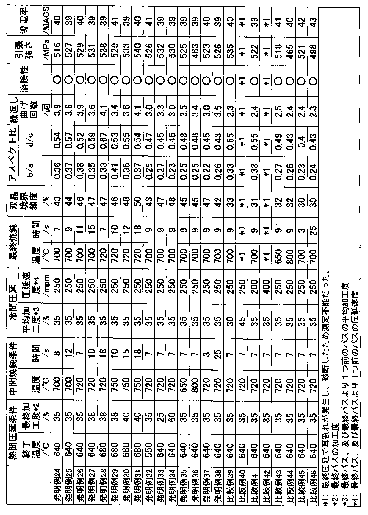
- Table 2 shows the conditions for hot rolling and intermediate annealing, conditions for cold rolling before final annealing (average working degree and rolling speed of the last pass and pass one before the final pass), final annealing conditions and test results. .
- Invention Examples 1 to 19 in Table 1 are within the scope of the present invention, they were alloy strips having good repeated bendability and weldability and sufficient strength.
- Inventive Example 20 has good repeated bendability and weldability due to the relatively small amount of Sn added, but the strength was lower than Inventive Examples 1-19.
- Inventive example 21 has a relatively large amount of Sn, and therefore the conductivity is lower than in inventive examples 1-19.
- Comparative Example 22 had a small amount of Zn and was inferior in repeated bending and reduced in strength as compared with the inventive examples. In Comparative Example 23, the amount of Zn was large and the repetitive bendability was good, but the surface oxide film became Zn-rich, so that the weldability was deteriorated and the conductivity was also lowered.
- Inventive Examples 24 to 38 in Table 2 were within the scope of the present invention, and thus were alloy strips having good repeated bendability and weldability and sufficient strength.
- Invention Example 32 has a low hot rolling end temperature
- Invention Examples 33 and 34 have a low or high hot rolling final workability
- Invention Examples 35 and 36 have a low or high intermediate annealing temperature
- Invention Examples 37 and 38 Is too short or too long for recrystallization annealing in intermediate annealing. Therefore, in these inventive examples, the aspect ratio is out of the preferred range, and the repeated bendability is inferior to those of the inventive examples 24-31.
- Comparative Example 39 the average degree of work in the final pass of the cold rolling after the intermediate annealing and the pass before the final pass is low, and in the Comparative Example 41, the average pass is one from the final pass of the cold rolling after the intermediate annealing and the final pass.
- the twin boundary frequency is low because the rolling speed of the previous pass is slow.
- Comparative Example 40 the average degree of work in the final pass of the cold rolling after the intermediate annealing and the pass before the final pass is too high, and in the comparative example 42, the average passability is 1 in the final pass of the cold rolling after the intermediate annealing and the final pass. Since the rolling speed of the previous pass was too high, an edge crack occurred at the edge of the material, and the material broke during the final rolling.
- Comparative Examples 43 and 44 the final annealing temperature was low or high.
- Comparative Examples 45 and 46 the final annealing time was short or long. Therefore, the twin boundary frequency was low, and the aspect ratio was outside the preferable specified range. For this reason, those that did not break in these comparative examples were inferior in repeatability to the invention examples.
Landscapes
- Chemical & Material Sciences (AREA)
- Chemical Kinetics & Catalysis (AREA)
- Electrochemistry (AREA)
- General Chemical & Material Sciences (AREA)
- Metallurgy (AREA)
- Materials Engineering (AREA)
- Engineering & Computer Science (AREA)
- Organic Chemistry (AREA)
- Mechanical Engineering (AREA)
- Physics & Mathematics (AREA)
- Thermal Sciences (AREA)
- Crystallography & Structural Chemistry (AREA)
- Conductive Materials (AREA)
- Connection Of Batteries Or Terminals (AREA)
- Electroplating Methods And Accessories (AREA)
Abstract
Description
(1)2~12質量%のZnを含有し、残部が銅および不可避不純物から成る銅合金であって、双晶境界頻度が40~70%である事を特徴とする、充電用電池タブに用いられるCu-Zn系合金条。
(2)更に0.1~0.8質量%のSnを含有する(1)に記載のCu-Zn系合金条。
(3)圧延平行方向および直角方向の結晶粒径のアスペクト比が0.3~0.7である(1)又は(2)に記載のCu-Zn系合金条。
(4)更にNi、Mg、Fe、P、AlおよびAgのなかの少なくとも一種以上を合計で0.005~0.5質量%含有する(1)~(3)いずれかに記載のCu-Zn系合金条。
(5)上記(1)~(4)いずれかに記載のCu-Zn系合金に0.3~2μmのSnめっきを施したCu-Zn系合金Snめっき合金条。
本発明例のCu-Zn系合金は、繰返し曲げ性および溶接性が良好で、電池用タブ材として好適である。
(A)Zn濃度
本発明の合金は、2~12質量%(以下%で表す)、好ましくは3~10%のZnを含有し、残部が銅および不可避不純物から成る銅合金である。Znが2%未満であるとタブとして必要な強度が不充分になる。また、導電率が高くなりすぎて溶接時にタブが溶損したり、電極側のステンレス板や軟鋼板に電流が流れにくくなるため溶接性が劣化する。Znが12%を超えると表面に形成される酸化膜の成分がZnリッチとなり溶接性が劣化する。
(B)Sn濃度
Snは圧延の際の加工硬化を促進する作用を持ち、強度上昇に寄与する。従って、本発明の合金は、更に0.1~0.8%、好ましくは0.2~0.6%のSnを含有してもよい。Snが0.1%未満では、所望の効果が得られず、Snが0.8%を超えると、導電率が低下する。
(C)上記以外の添加元素
本発明の合金には、合金の強度、耐熱性、耐応力緩和性等を改善する目的で、Ni、Mg、Fe、P、AlおよびAgの中の一種以上を合計で0.005~0.5%添加することができる。総量が0.005%未満では所望の特性が得られず、総量が0.5%を超えると所望の特性は得られるものの、導電性や曲げ加工性が低下する。
双晶境界頻度が40%未満の場合、繰返し曲げ性が劣化する。本発明の成分系で双晶境界頻度が70%を超える様に調整する事は工業的に困難なため、上限は70%とした。
双晶境界とは、双晶関係にある2つの結晶の境界を指し、この境界を境に2つの結晶は鏡面対称の関係にある。対応粒界理論によれば双晶境界はΣ3の結晶粒界に相当する。双晶境界は境界間の原子の整合性が良い為、境界近傍において不均一変形が起こりにくく、曲げ変形時、境界近傍を基点とする割れやしわが発生しにくい。
双晶境界頻度とは、結晶粒界と双晶境界を合わせた全境界中の双晶境界の割合を言う。双晶の発生頻度は積層欠陥エネルギーと関係があり、積層欠陥エネルギーが低いほど、双晶境界頻度は高くなる。
本発明の組成は、黄銅(Cu65%、Zn35%)に比べると溶接性及び導電性を満たすためにZn量が少ない。積層欠陥エネルギーはZn量の減少に伴い高くなるため、双晶境界頻度は黄銅に比べ低くなり、通常の工程で40%を超える高い双晶境界頻度を得る事は難しかった。発明者は本発明の合金において、双晶境界頻度を上昇させるため、製造工程と双晶境界頻度の関係について鋭意調査を行なった結果、最終焼鈍の前に実施される冷間圧延の条件が重要であることが判明した。圧延では一対のロール間に材料を繰返し通過(パス)させ、目標の板厚に仕上げてゆく。この一連のパスにおいて、最終パスおよび最終パスより1つ前のパスで、1パス当たりの加工度を上昇させ、圧延速度を高速化した仕上圧延を行ない、その後、適切な条件で最終焼鈍を行なうと、40%を超える高い双晶境界頻度が得られる事を見出した。
本発明では、繰返し曲げ性をさらに改善するために、金属組織と繰返し曲げ性について研究を進めた結果、最終焼鈍後の金属組織を均一な等軸粒に制御する事で繰返し曲げ性が改善される事が明らかになった。最終製品には30~60%の冷間圧延が施されるため、繰返し曲げ性を改善するには、最終製品における圧延平行方向および直角方向の結晶粒径のアスペクト比b/aおよびd/cを0.3~0.7に制御する事が好ましい。より好ましくはb/aが0.3~0.5であり、d/cが0.5~0.7である。図1は試料断面にて観察される結晶粒の模式図である。
圧延平行方向および直角方向の結晶粒径のアスペクト比b/a及び/又はd/cが、0.3未満であるか0.7を超えると繰返し曲げ時にひずみが局部的に集中し、せん断帯が形成され、繰返し曲げ性が劣化する。
本発明の合金条の組成は黄銅に比べZn量が少ないため、再結晶後の金属組織は混粒になりやすい。また、熱間圧延時に途中パスにて再結晶が終了すると、圧延方向に伸長した粗大結晶粒が残留し、金属組織の等軸化を阻害する。従って、最終焼鈍時に均一な等軸粒を得るには、熱間圧延の終了温度を制御し、適切な加工度で圧延する事で動的再結晶により金属組織を等軸化した後、複数回の圧延と焼鈍を繰り返す必要がある。
本発明の平均結晶粒径は、好ましくは12μm以下、更に好ましくは7μm以下である。
本発明の合金条の引張強さ(JISZ2241)は、通常420MPa以上、好ましくは450MPa以上、更に好ましくは500MPa以上であるとタブ材料として好適に使用できる。
本発明の合金条の導電率(JISH0505)は、70%IACS以下、更に好ましくは60%IACS以下であるとタブ材料として適切に使用できる。70%IACSを超えると抵抗溶接時に溶損が起こったり、電極側の金属板に充分な電流が流れず、溶接性が低下する。
本発明の合金条の繰り返し曲げ性は、好ましくは3.0回以上、更に好ましくは3.2回以上であるとタブ材料として好ましい。
本発明の合金条には0.3~2μmのSnめっきを施してCu-Zn系合金Snめっき合金条とすることができる。Snめっき方法は従来法で行うことができ、0.3~2μm程度のSnめっきを施すことにより溶接性がより良好となる。
本発明のCu-Zn系合金条の製造工程は、基本的には通常の合金条と同様であり、溶解鋳造、均質化焼鈍及び熱間圧延、面削の後、複数回の冷間圧延、焼鈍を繰返し、製造される。
しかし、本発明の合金条を製造するためには、本発明の範囲の双晶境界頻度となるように製造条件を制御する必要がある。
最終焼鈍前の冷間圧延の最終パス、及び最終パスより1つ前のパスの平均加工度としては32~40%、圧延速度としては220~350mpmが適切である。前述の範囲より加工度が低い、又は圧延速度が遅い場合、双晶境界頻度が低くなり繰返し曲げ性が劣化する。加工度が高い、又は圧延速度が速い場合、材料縁端部に耳割れ(エッジクラック)が発生し、圧延時に材料が破断する等、著しく製造性が低下する。
最終焼鈍の条件としては、温度660~760℃、焼鈍時間5~20sが適切である。前述の範囲より温度が低い、又は時間が短い場合、最終焼鈍が不充分なため、双晶境界頻度が低下し、繰返し曲げ性が劣化する。最終焼鈍温度が高い、又は時間が長い場合、結晶粒の著しい粗大化が起こり、双晶境界頻度が低下し、繰返し曲げ性が劣化する。
以下の製造条件を調整する事で、さらに繰返し曲げ性を改善する事が出来る。
熱間圧延の終了温度は好ましくは600~750℃であり、最終加工度は好ましくは30~55%である。これらが範囲外であるとアスペクト比が本発明で好ましい範囲外となり、繰返し曲げ性が劣化する。
中間焼鈍温度は好ましくは680~780℃で5~20秒であり、焼鈍条件が前述の範囲外であると、アスペクト比が本発明で好ましい範囲外となり、繰返し曲げ性が劣化する。
[双晶境界頻度] 各銅合金板について、FESEM(Field Emission Scanning Electron Microscope)によるEBSP(Electron Backscattering Pattern)法で測定した。
[アスペクト比] 各銅合金板について、圧延方向に平行な断面および垂直な断面の結晶粒径をJISH0501の切断法に準じ測定し算出した。図1に示す圧延方向と平行な断面では、圧延面に対して平行な方向と、圧延面に対して直角な方向の2方向でそれぞれ結晶粒径を測定し、平行方向の測定値を長径a、直角方向の測定値を短径bとした。圧延方向と垂直な断面では、圧延方向に対して平行な方向と、圧延方向に対して直角な方向のそれぞれ2方向で結晶粒径を測定し、平行方向の測定値を長径c、直角方向の測定値を短径dとした。
[繰返し曲げ性] 長手方向が圧延方向に平行となる様に、厚さ0.15mm、幅10mm×長さ40mmの最終品試験片を4個作製し、試験片の長手方向に直角な方向を曲げ軸として、180°曲げを行なった後、曲げ戻した。これを1回として、試料が破断するまで繰返し曲げを行い、試料4個の平均破断(繰返し曲げ)回数を求めた。
[引張強さ] 各銅合金板について、圧延方向に平行な方向に引張試験を行ない、JISZ2241に準拠して求めた。
[導電率] 各銅合金板について、JISH0505に準拠し、ダブルブリッジ装置を用いた四端子法により求めた体積抵抗率から%IACSを算出した。
高周波誘導炉で電気銅を溶解し、溶湯表面を木炭被覆した後、合金元素を添加し所望の組成に溶湯を調整した。鋳込温度1200℃で鋳造を行い、得られたインゴットを850℃で3時間加熱後、熱間圧延の最終パスの加工度が35%になる様に、板厚8mmまで圧延し、熱間圧延終了温度を650℃以上に調整した。表面に生じた酸化スケールを面削にて除去した。その後、冷間圧延で板厚1.5mmまで加工し、700℃にて12秒間の中間焼鈍を行い、さらに0.35mmまでの冷間圧延では、最終パス及び最終パスより1つ前のパスの平均加工度が35%、最終パスおよび最終パスより1つ前のパスの圧延速度がともに250m/minとなる様に調整した。この冷間圧延後、680℃にて10秒間の最終焼鈍を行ない、最終焼鈍後の銅合金板を冷間圧延し、0.15mmの板に仕上げた。中間焼鈍および最終焼鈍はアンモニア分解ガス雰囲気中で、連続ラインにて行なった。表1に試験結果を示す。
高周波誘導炉で電気銅を溶解し、溶湯表面を木炭被覆した後、8.0%Zn、0.30%Sn及びCuの組成になるように溶湯内にZn及びSnを添加して成分を調整し、鋳込温度1200℃で鋳造を行なった。得られたインゴットを900℃で3時間加熱後、熱間圧延を行ない、板厚8mmの銅合金板を作製し、表面に生じた酸化スケールを面削にて除去した。その後、冷間圧延で板厚1.5mmまで加工し、中間焼鈍を行なった後、板厚0.25mmまで冷間圧延を実施した。更に最終焼鈍を行ない、最終焼鈍後の銅合金板を冷間圧延し、0.15mmの板に仕上げた。中間焼鈍および最終焼鈍はアンモニア分解ガス雰囲気中で、連続ラインを用いて行なった。表2に熱間圧延及び中間焼鈍の条件、最終焼鈍前の冷間圧延の条件(最終パスおよび最終パスより1つ前のパスの平均加工度と圧延速度)、最終焼鈍条件並びに試験結果を示す。
発明例32は熱間圧延の終了温度が低く、発明例33及び34は熱間圧延の最終加工度が低く又は高く、発明例35及び36は中間焼鈍温度が低く又は高く、発明例37及び38は中間焼鈍での再結晶焼鈍時間が短い又は長すぎる。そのため、これら発明例ではアスペクト比が好ましい範囲外となり、繰返し曲げ性が、発明例24~31に比べ劣った。
比較例39は中間焼鈍後の冷間圧延の最終パスおよび最終パスより1つ前のパスの平均加工度が低く、比較例41は中間焼鈍後の冷間圧延の最終パスおよび最終パスより1つ前のパスの圧延速度が遅いため双晶境界頻度が低い。比較例40は中間焼鈍後の冷間圧延の最終パスおよび最終パスより1つ前のパスの平均加工度が高すぎ、比較例42は中間焼鈍後の冷間圧延の最終パスおよび最終パスより1つ前のパスの圧延速度が速すぎるため材料縁端部に耳割れが発生し、最終圧延時に材料が破断した。比較例43及び44は最終焼鈍温度が低く又は高く、比較例45及び46は最終焼鈍時間が短い又は長いため、双晶境界頻度が低く、アスペクト比も好ましい規定範囲外となった。このため、これら比較例で破断しなかったものは繰り返し曲げ性が発明例に比べ劣った。

Claims (6)
- 2~12質量%のZnを含有し、残部が銅および不可避不純物から成る銅合金であって、双晶境界頻度が40~70%である事を特徴とする、充電用電池タブに用いられるCu-Zn系合金条。
- 更に0.1~0.8質量%のSnを含有する請求項1に記載のCu-Zn系合金条。
- 圧延平行方向および直角方向の結晶粒径のアスペクト比が0.3~0.7である請求項1に記載のCu-Zn系合金条。
- 更にNi、Mg、Fe、P、AlおよびAgのなかの少なくとも一種以上を合計で0.005~0.5質量%含有する請求項1~3いずれか1項に記載のCu-Zn系合金条。
- 請求項1~3いずれか1項に記載のCu-Zn系合金に0.3~2μmのSnめっきを施したCu-Zn系合金Snめっき合金条。
- 請求項4に記載のCu-Zn系合金に0.3~2μmのSnめっきを施したCu-Zn系合金Snめっき合金条。
Priority Applications (2)
| Application Number | Priority Date | Filing Date | Title |
|---|---|---|---|
| KR1020127028279A KR101414882B1 (ko) | 2010-03-31 | 2011-03-25 | 전지 접속 탭 재료용 Cu-Zn 계 합금조 |
| CN2011800169739A CN102812137A (zh) | 2010-03-31 | 2011-03-25 | 用于电池接头材料的Cu-Zn系合金条 |
Applications Claiming Priority (2)
| Application Number | Priority Date | Filing Date | Title |
|---|---|---|---|
| JP2010-081028 | 2010-03-31 | ||
| JP2010081028A JP5490594B2 (ja) | 2010-03-31 | 2010-03-31 | 電池接続タブ材料用Cu−Zn系合金条 |
Publications (1)
| Publication Number | Publication Date |
|---|---|
| WO2011125555A1 true WO2011125555A1 (ja) | 2011-10-13 |
Family
ID=44762508
Family Applications (1)
| Application Number | Title | Priority Date | Filing Date |
|---|---|---|---|
| PCT/JP2011/057438 Ceased WO2011125555A1 (ja) | 2010-03-31 | 2011-03-25 | 電池接続タブ材料用Cu-Zn系合金条 |
Country Status (5)
| Country | Link |
|---|---|
| JP (1) | JP5490594B2 (ja) |
| KR (1) | KR101414882B1 (ja) |
| CN (1) | CN102812137A (ja) |
| TW (1) | TWI443203B (ja) |
| WO (1) | WO2011125555A1 (ja) |
Cited By (1)
| Publication number | Priority date | Publication date | Assignee | Title |
|---|---|---|---|---|
| US9957589B2 (en) | 2013-01-25 | 2018-05-01 | Mitsubishi Shindoh Co., Ltd. | Copper-alloy plate for terminal/connector material, and method for producing copper-alloy plate for terminal/connector material |
Families Citing this family (11)
| Publication number | Priority date | Publication date | Assignee | Title |
|---|---|---|---|---|
| WO2012153728A1 (ja) * | 2011-05-10 | 2012-11-15 | Jx日鉱日石金属株式会社 | Niめっき金属板、溶接構造体、及び電池用材料の製造方法 |
| JP5130406B1 (ja) * | 2012-03-29 | 2013-01-30 | Jx日鉱日石金属株式会社 | Cu−Zn−Sn系銅合金条 |
| JP6097606B2 (ja) * | 2012-10-26 | 2017-03-15 | 三菱マテリアル株式会社 | 電子・電気機器用銅合金、電子・電気機器用銅合金薄板、電子・電気機器用導電部品及び端子 |
| JP6166891B2 (ja) * | 2012-12-14 | 2017-07-19 | 三菱マテリアル株式会社 | 電子・電気機器用銅合金、電子・電気機器用銅合金薄板、電子・電気機器用導電部品及び端子 |
| TWI486462B (zh) * | 2013-01-28 | 2015-06-01 | Mitsubishi Shindo Kk | 端子和連接器材料用銅合金板、以及端子和連接器材料用銅合金板的製造方法 |
| JP6097575B2 (ja) * | 2013-01-28 | 2017-03-15 | 三菱マテリアル株式会社 | 電子・電気機器用銅合金、電子・電気機器用銅合金薄板、電子・電気機器用導電部品及び端子 |
| JP6097576B2 (ja) * | 2013-01-28 | 2017-03-15 | 三菱マテリアル株式会社 | 電子・電気機器用銅合金、電子・電気機器用銅合金薄板、電子・電気機器用導電部品及び端子 |
| JP6136069B2 (ja) * | 2013-05-08 | 2017-05-31 | 住友電気工業株式会社 | リード導体、及び電力貯蔵デバイス |
| JP6829179B2 (ja) * | 2017-11-15 | 2021-02-10 | Jx金属株式会社 | 耐食性CuZn合金 |
| CN109439933A (zh) * | 2018-08-31 | 2019-03-08 | 新昌县金声铜业有限公司 | 一种强抑菌铜合金及其制备方法 |
| CN109321779A (zh) * | 2018-10-26 | 2019-02-12 | 浙江星康铜业有限公司 | 一种抗折压的铜板材及其制备方法 |
Citations (5)
| Publication number | Priority date | Publication date | Assignee | Title |
|---|---|---|---|---|
| JPH06220594A (ja) * | 1993-01-21 | 1994-08-09 | Mitsui Mining & Smelting Co Ltd | 加工性の良い電気部品用銅合金の製造方法 |
| JP2006299287A (ja) * | 2005-04-15 | 2006-11-02 | Nikko Kinzoku Kk | 複相銅合金、ばね材及び箔体、並びに複相銅合金の製造方法 |
| JP2007270214A (ja) * | 2006-03-30 | 2007-10-18 | Nikko Kinzoku Kk | 曲げ加工性に優れるCu−Zn−Sn系合金条 |
| JP2008106356A (ja) * | 2006-09-27 | 2008-05-08 | Dowa Metaltech Kk | 銅合金板材およびその製造法 |
| JP2009079270A (ja) * | 2007-09-26 | 2009-04-16 | Dowa Metaltech Kk | Cu−Sn−P系銅合金板材およびその製造法並びにコネクタ |
Family Cites Families (2)
| Publication number | Priority date | Publication date | Assignee | Title |
|---|---|---|---|---|
| ATE507316T1 (de) * | 2002-03-01 | 2011-05-15 | Showa Denko Kk | Verfahren zur herstellung einer platte aus al-mg- si-legierung |
| TWI374950B (zh) * | 2007-03-22 | 2012-10-21 | Jx Nippon Mining & Metals Corp | 印刷基板端子 |
-
2010
- 2010-03-31 JP JP2010081028A patent/JP5490594B2/ja active Active
-
2011
- 2011-03-14 TW TW100108503A patent/TWI443203B/zh active
- 2011-03-25 CN CN2011800169739A patent/CN102812137A/zh active Pending
- 2011-03-25 KR KR1020127028279A patent/KR101414882B1/ko not_active Expired - Fee Related
- 2011-03-25 WO PCT/JP2011/057438 patent/WO2011125555A1/ja not_active Ceased
Patent Citations (5)
| Publication number | Priority date | Publication date | Assignee | Title |
|---|---|---|---|---|
| JPH06220594A (ja) * | 1993-01-21 | 1994-08-09 | Mitsui Mining & Smelting Co Ltd | 加工性の良い電気部品用銅合金の製造方法 |
| JP2006299287A (ja) * | 2005-04-15 | 2006-11-02 | Nikko Kinzoku Kk | 複相銅合金、ばね材及び箔体、並びに複相銅合金の製造方法 |
| JP2007270214A (ja) * | 2006-03-30 | 2007-10-18 | Nikko Kinzoku Kk | 曲げ加工性に優れるCu−Zn−Sn系合金条 |
| JP2008106356A (ja) * | 2006-09-27 | 2008-05-08 | Dowa Metaltech Kk | 銅合金板材およびその製造法 |
| JP2009079270A (ja) * | 2007-09-26 | 2009-04-16 | Dowa Metaltech Kk | Cu−Sn−P系銅合金板材およびその製造法並びにコネクタ |
Cited By (2)
| Publication number | Priority date | Publication date | Assignee | Title |
|---|---|---|---|---|
| US9957589B2 (en) | 2013-01-25 | 2018-05-01 | Mitsubishi Shindoh Co., Ltd. | Copper-alloy plate for terminal/connector material, and method for producing copper-alloy plate for terminal/connector material |
| US10020088B2 (en) * | 2013-01-25 | 2018-07-10 | Mitsubishi Shindoh Co., Ltd. | Copper-alloy plate for terminal/connector material, and method for producing copper-alloy plate for terminal/connector material |
Also Published As
| Publication number | Publication date |
|---|---|
| KR20120130343A (ko) | 2012-11-30 |
| JP5490594B2 (ja) | 2014-05-14 |
| TWI443203B (zh) | 2014-07-01 |
| CN102812137A (zh) | 2012-12-05 |
| KR101414882B1 (ko) | 2014-07-03 |
| TW201142049A (en) | 2011-12-01 |
| JP2011214036A (ja) | 2011-10-27 |
Similar Documents
| Publication | Publication Date | Title |
|---|---|---|
| JP5490594B2 (ja) | 電池接続タブ材料用Cu−Zn系合金条 | |
| EP3040430B1 (en) | Copper alloy sheet material and method for producing same, and current-carrying component | |
| US9234263B2 (en) | Weldment | |
| KR101518142B1 (ko) | 전지 집전체용 알루미늄 경질 박 | |
| US9809872B2 (en) | Dilute copper alloy material, dilute copper alloy wire, dilute copper alloy twisted wire and cable using the same, coaxial cable and composite cable, and method of manufacturing dilute copper alloy material and dilute copper alloy wire | |
| CN108026612B (zh) | 铜合金板材及其制造方法 | |
| JP5189715B1 (ja) | 優れた耐疲労特性を有するCu−Mg−P系銅合金板及びその製造方法 | |
| CN111566240B (zh) | 铝合金材料以及使用其的导电构件、电池用构件、紧固部件、弹簧用部件及结构用部件 | |
| JP5927614B2 (ja) | 電池集電体用アルミニウム硬質箔 | |
| TWI429764B (zh) | Cu-Co-Si alloy for electronic materials | |
| EP2641983A1 (en) | Cu-Ni-Si-Co COPPER ALLOY FOR ELECTRON MATERIAL AND METHOD FOR PRODUCING SAME | |
| US9805836B2 (en) | Dilute copper alloy material and method of manufacturing dilute copper alloy member excellent in characteristics of resistance to hydrogen embrittlement | |
| US20180211741A1 (en) | Copper alloy for electronic/electrical device, plastically-worked copper alloy material for electronic/electrical device, component for electronic/electrical device, terminal, and busbar | |
| JP5534610B2 (ja) | Cu−Co−Si系合金条 | |
| JP6730784B2 (ja) | 電子部品用Cu−Ni−Co−Si合金 | |
| JP5140171B2 (ja) | 充電用電池タブ材に用いられる銅合金条 | |
| JP2001011550A (ja) | 銅合金圧延箔 | |
| EP2444978A2 (en) | Solar cell conductor and method of manufacturing the same | |
| JP4157899B2 (ja) | 曲げ加工性に優れた高強度銅合金板 | |
| JP4688100B2 (ja) | 電気接点用Cuめっき鋼板の製造方法 | |
| JP5130406B1 (ja) | Cu−Zn−Sn系銅合金条 | |
| JP2011219833A (ja) | プロジェクション溶接特性に優れたCu−Ni−Si系銅合金、及びその製造方法 | |
| JP2012211376A (ja) | 電池接続タブ用銅合金条 | |
| JP2013040393A (ja) | プロジェクション溶接特性に優れたCu−Ni−Si系銅合金、及びその製造方法 | |
| JP6762453B1 (ja) | 銅合金板材およびその製造方法 |
Legal Events
| Date | Code | Title | Description |
|---|---|---|---|
| WWE | Wipo information: entry into national phase |
Ref document number: 201180016973.9 Country of ref document: CN |
|
| 121 | Ep: the epo has been informed by wipo that ep was designated in this application |
Ref document number: 11765456 Country of ref document: EP Kind code of ref document: A1 |
|
| NENP | Non-entry into the national phase |
Ref country code: DE |
|
| ENP | Entry into the national phase |
Ref document number: 20127028279 Country of ref document: KR Kind code of ref document: A |
|
| 122 | Ep: pct application non-entry in european phase |
Ref document number: 11765456 Country of ref document: EP Kind code of ref document: A1 |