WO2011125324A1 - 熱交換器の製造装置および製造方法 - Google Patents
熱交換器の製造装置および製造方法 Download PDFInfo
- Publication number
- WO2011125324A1 WO2011125324A1 PCT/JP2011/002012 JP2011002012W WO2011125324A1 WO 2011125324 A1 WO2011125324 A1 WO 2011125324A1 JP 2011002012 W JP2011002012 W JP 2011002012W WO 2011125324 A1 WO2011125324 A1 WO 2011125324A1
- Authority
- WO
- WIPO (PCT)
- Prior art keywords
- tube
- core tube
- winding
- core
- wound
- Prior art date
- Legal status (The legal status is an assumption and is not a legal conclusion. Google has not performed a legal analysis and makes no representation as to the accuracy of the status listed.)
- Ceased
Links
Images





Classifications
-
- F—MECHANICAL ENGINEERING; LIGHTING; HEATING; WEAPONS; BLASTING
- F28—HEAT EXCHANGE IN GENERAL
- F28D—HEAT-EXCHANGE APPARATUS, NOT PROVIDED FOR IN ANOTHER SUBCLASS, IN WHICH THE HEAT-EXCHANGE MEDIA DO NOT COME INTO DIRECT CONTACT
- F28D7/00—Heat-exchange apparatus having stationary tubular conduit assemblies for both heat-exchange media, the media being in contact with different sides of a conduit wall
- F28D7/0008—Heat-exchange apparatus having stationary tubular conduit assemblies for both heat-exchange media, the media being in contact with different sides of a conduit wall the conduits for one medium being in heat conductive contact with the conduits for the other medium
- F28D7/0016—Heat-exchange apparatus having stationary tubular conduit assemblies for both heat-exchange media, the media being in contact with different sides of a conduit wall the conduits for one medium being in heat conductive contact with the conduits for the other medium the conduits for one medium or the conduits for both media being bent
-
- B—PERFORMING OPERATIONS; TRANSPORTING
- B23—MACHINE TOOLS; METAL-WORKING NOT OTHERWISE PROVIDED FOR
- B23K—SOLDERING OR UNSOLDERING; WELDING; CLADDING OR PLATING BY SOLDERING OR WELDING; CUTTING BY APPLYING HEAT LOCALLY, e.g. FLAME CUTTING; WORKING BY LASER BEAM
- B23K1/00—Soldering, e.g. brazing, or unsoldering
- B23K1/0008—Soldering, e.g. brazing, or unsoldering specially adapted for particular articles or work
- B23K1/0012—Brazing of heat exchangers
-
- B—PERFORMING OPERATIONS; TRANSPORTING
- B23—MACHINE TOOLS; METAL-WORKING NOT OTHERWISE PROVIDED FOR
- B23K—SOLDERING OR UNSOLDERING; WELDING; CLADDING OR PLATING BY SOLDERING OR WELDING; CUTTING BY APPLYING HEAT LOCALLY, e.g. FLAME CUTTING; WORKING BY LASER BEAM
- B23K1/00—Soldering, e.g. brazing, or unsoldering
- B23K1/012—Soldering with the use of hot gas
-
- B—PERFORMING OPERATIONS; TRANSPORTING
- B23—MACHINE TOOLS; METAL-WORKING NOT OTHERWISE PROVIDED FOR
- B23K—SOLDERING OR UNSOLDERING; WELDING; CLADDING OR PLATING BY SOLDERING OR WELDING; CUTTING BY APPLYING HEAT LOCALLY, e.g. FLAME CUTTING; WORKING BY LASER BEAM
- B23K3/00—Tools, devices or special appurtenances for soldering, e.g. brazing, or unsoldering, not specially adapted for particular methods
- B23K3/06—Solder feeding devices; Solder melting pans
- B23K3/0607—Solder feeding devices
- B23K3/063—Solder feeding devices for wire feeding
-
- B—PERFORMING OPERATIONS; TRANSPORTING
- B23—MACHINE TOOLS; METAL-WORKING NOT OTHERWISE PROVIDED FOR
- B23K—SOLDERING OR UNSOLDERING; WELDING; CLADDING OR PLATING BY SOLDERING OR WELDING; CUTTING BY APPLYING HEAT LOCALLY, e.g. FLAME CUTTING; WORKING BY LASER BEAM
- B23K3/00—Tools, devices or special appurtenances for soldering, e.g. brazing, or unsoldering, not specially adapted for particular methods
- B23K3/08—Auxiliary devices therefor
- B23K3/087—Soldering or brazing jigs, fixtures or clamping means
-
- B—PERFORMING OPERATIONS; TRANSPORTING
- B23—MACHINE TOOLS; METAL-WORKING NOT OTHERWISE PROVIDED FOR
- B23K—SOLDERING OR UNSOLDERING; WELDING; CLADDING OR PLATING BY SOLDERING OR WELDING; CUTTING BY APPLYING HEAT LOCALLY, e.g. FLAME CUTTING; WORKING BY LASER BEAM
- B23K37/00—Auxiliary devices or processes, not specially adapted for a procedure covered by only one of the other main groups of this subclass
- B23K37/04—Auxiliary devices or processes, not specially adapted for a procedure covered by only one of the other main groups of this subclass for holding or positioning work
- B23K37/047—Auxiliary devices or processes, not specially adapted for a procedure covered by only one of the other main groups of this subclass for holding or positioning work moving work to adjust its position between soldering, welding or cutting steps
-
- B—PERFORMING OPERATIONS; TRANSPORTING
- B23—MACHINE TOOLS; METAL-WORKING NOT OTHERWISE PROVIDED FOR
- B23K—SOLDERING OR UNSOLDERING; WELDING; CLADDING OR PLATING BY SOLDERING OR WELDING; CUTTING BY APPLYING HEAT LOCALLY, e.g. FLAME CUTTING; WORKING BY LASER BEAM
- B23K37/00—Auxiliary devices or processes, not specially adapted for a procedure covered by only one of the other main groups of this subclass
- B23K37/04—Auxiliary devices or processes, not specially adapted for a procedure covered by only one of the other main groups of this subclass for holding or positioning work
- B23K37/053—Auxiliary devices or processes, not specially adapted for a procedure covered by only one of the other main groups of this subclass for holding or positioning work aligning cylindrical work; Clamping devices therefor
-
- B—PERFORMING OPERATIONS; TRANSPORTING
- B23—MACHINE TOOLS; METAL-WORKING NOT OTHERWISE PROVIDED FOR
- B23K—SOLDERING OR UNSOLDERING; WELDING; CLADDING OR PLATING BY SOLDERING OR WELDING; CUTTING BY APPLYING HEAT LOCALLY, e.g. FLAME CUTTING; WORKING BY LASER BEAM
- B23K2101/00—Articles made by soldering, welding or cutting
- B23K2101/04—Tubular or hollow articles
- B23K2101/06—Tubes
- B23K2101/08—Tubes finned or ribbed
-
- B—PERFORMING OPERATIONS; TRANSPORTING
- B23—MACHINE TOOLS; METAL-WORKING NOT OTHERWISE PROVIDED FOR
- B23K—SOLDERING OR UNSOLDERING; WELDING; CLADDING OR PLATING BY SOLDERING OR WELDING; CUTTING BY APPLYING HEAT LOCALLY, e.g. FLAME CUTTING; WORKING BY LASER BEAM
- B23K2101/00—Articles made by soldering, welding or cutting
- B23K2101/04—Tubular or hollow articles
- B23K2101/14—Heat exchangers
Definitions
- the present invention relates to a heat exchanger manufacturing apparatus and manufacturing method, and particularly relates to a heat exchanger having a core tube and a wound tube wound around the outer surface of the core tube.
- an air conditioner or a hot water supply apparatus includes a core tube that forms a flow path of a first fluid, and a winding tube that is wound around the outer peripheral surface of the core tube to form a flow path of a second fluid.
- a heat exchanger that exchanges heat between the fluid and the second fluid is provided.
- Such a heat exchanger manufacturing apparatus is disclosed in Patent Document 1 and Patent Document 2.
- this heat exchanger The manufacturing process of this heat exchanger will be described. First, a plurality of wound tubes are spirally wound around the core tube. And the brazing material formed linearly is installed on the winding tube. Next, the core tube and the wound tube are placed in a heating furnace and heated. In the heating furnace, the molten brazing material enters between the core tube and the winding tube. Thereafter, the brazing material is cooled and solidified, whereby the core tube and the wound tube are bonded and fixed.
- the melting temperature of the brazing material is relatively high, there is a problem that the strength of the heated core tube and the wound tube is lowered. In addition, there is a problem that the heat energy required to melt the brazing material becomes large.
- a manufacturing apparatus that joins the core tube and the wound tube with solder whose melting temperature is lower than the melting temperature of the brazing material is conceivable.
- this manufacturing apparatus first, a plurality of wound tubes are wound spirally around a core tube. Then, the core tube and the winding tube are immersed in a solder bath containing molten solder. In the solder tank, the melted solder enters between the core tube and the winding tube. Next, after raising the core tube and the winding tube, the solder is cooled to join the core tube and the winding tube.
- the present invention has been made in view of such a point, and an object thereof is to improve the heat transfer coefficient of the heat exchanger by improving the adhesion between the winding tube and the core tube.
- 1st invention is the manufacturing apparatus of the heat exchanger which heat-exchanges the fluid which flows through the inside of a core pipe (2), and the fluid which flows through the winding pipe (3) helically wound around this core pipe (2).
- a rotating mechanism (10) configured to be movable in the axial direction of the core tube (2) formed in a straight tube shape and rotating the core tube (2) in the circumferential direction, and the rotating mechanism (10) And a winding mechanism (90) for spirally winding the winding tube (3) around the core tube (2) rotated by a portion of the core tube (2) around which the winding tube (3) is wound
- the core tube (2) is rotated in the circumferential direction by the rotation mechanism (10).
- the winding mechanism (90) winds the winding tube (3) spirally around the rotating core tube (2) and moves the core tube (2) in the axial direction.
- a heating mechanism (30) heats a part of part by which the winding tube (3) was wound among the core tubes (2).
- the solder supply mechanism (41) supplies solder between the core tube (2) and the winding tube (3) located in the portion heated to a high temperature by the heating mechanism (30).
- the core tube (2) is provided with a protrusion forming mechanism (60) that forms a protrusion protruding toward the inner peripheral surface of the core tube (2).
- the projection forming mechanism (60) presses the outer peripheral surface of the core tube (2) to Protrusions projecting toward the inner peripheral surface of the tube (2) are formed.
- the winding mechanism (90) is a core tube (2) that is plastically deformed into a spiral shape and is rotationally driven by the rotating mechanism (10).
- the mold member (91) plastically deforms the winding tube (3) in a spiral shape.
- the winding mechanism (90) winds the spiral winding tube (3) around the rotating core tube (2)
- the core tube (2) is driven in the axial direction via the winding tube (3).
- the core tube (2) moves in the axial direction.
- the solder supply mechanism (41) is configured to be movable with respect to the core tube (2), while the wound tube wound around the core tube (2).
- the position detector (81) detects the position of the wound tube (3) wound around the core tube (2). Then, the control unit (82) adjusts the position of the solder supply mechanism (41) based on the detected position of the winding tube (3).
- the heating mechanism (30) includes a temperature adjusting section (32) for adjusting the temperatures of the core tube (2) and the wound tube (3). It is.
- the temperature of the core tube (2) and the winding tube (3) is adjusted by the temperature adjusting unit (32).
- the temperature adjusting section (32) controls the temperature of the core tube (2) and the winding tube (3) by adjusting the heating amount of the heating mechanism (30). It is configured to adjust.
- the temperature adjusting unit (32) adjusts the temperature of the core tube (2) and the wound tube (3) by adjusting the heating amount of the heating mechanism (30).
- the heating mechanism (30) includes a workpiece temperature measuring unit (33) for measuring temperatures of the heated core tube (2) and the wound tube (3). It is a thing. And the said temperature control part (32) is comprised so that the heating amount of the said heating mechanism (30) may be adjusted based on the measured value of the said workpiece
- the temperature of the core tube (2) and the winding tube (3) is measured by the workpiece temperature measurement unit (33). And based on the measured value by the said measurement, a temperature control part (32) adjusts the heating amount of a heating mechanism (30).
- the heating mechanism (30) includes an ambient temperature measuring section (34) for measuring temperatures around the core tube (2) and the wound tube (3). It is. And the said temperature control part (32) is comprised so that the heating amount of the said heating mechanism (30) may be adjusted based on the measured value of the said ambient temperature measurement part (34).
- the ambient temperature of the core tube (2) and the wound tube (3) is measured by the ambient temperature measurement unit (34). And based on the measured value by the said measurement, a temperature control part (32) adjusts the heating amount of a heating mechanism (30).
- a ninth invention is a method of manufacturing a heat exchanger for exchanging heat between a fluid flowing in the core tube (2) and a fluid flowing in the winding tube (3) spirally wound around the core tube (2).
- a winding step of spirally winding the winding tube (3) around the straight tubular core tube (2) rotating in the circumferential direction, and moving the core tube (2) in the axial direction;
- a heating step of heating a part of the core tube (2) around which the winding tube (3) is wound in the process, and a core tube (2) heated in the heating step;
- the core tube (2) rotates in the circumferential direction in the winding step to wind the winding tube (3) around the core tube (2), and the core tube (2) moves in the axial direction. And while a core pipe (2) moves to an axial direction and rotates to a circumferential direction, a part of part by which the wound pipe (3) was wound among core pipes (2) was heated. Subsequently, the core tube (2) and the winding tube (3) move in the axial direction of the core tube (2) and are heated by the heating mechanism (30) to reach the high temperature portion (2) Solder is supplied between the winding tubes (3).
- the core tube (2) is pressed against the outer peripheral surface of the core tube (2) of the core tube (2) before the winding tube (3) is wound.
- the outer peripheral surface of the core tube (2) of the core tube (2) before the winding tube (3) is wound is pressed, and the core tube (2) is pressed against the core tube (2 ) Projecting toward the inner peripheral surface side.
- the core tube (3) is wound around the core tube (2) and then the core tube is compared with the prior art in which the core tube (2) and the wound tube (3) are joined after a while. Adhesion between (2) and winding tube (3) can be improved. As a result, the heat transfer coefficient of the heat exchanger can be improved.
- the outer peripheral surface of the core tube (2) is pressed to the inner peripheral surface side of the core tube (2). Since the projection forming mechanism (60) for forming the projections projecting is provided, it is possible to form the projections on the core tube (2) and wind the winding tube (3).
- the winding mechanism (90) winds the winding tube (3) spirally around the core tube (2) by the mold member (91) and the core through the winding tube (3). Because the driving force in the axial direction is applied to the tube (2), the core tube (2) is moved in the axial direction while the winding tube (3) is spirally wound around the core tube (2). Can do. That is, the winding mechanism (90) constitutes a moving mechanism that moves the core tube (2) in the axial direction.
- the position of the winding tube (3) wound around the core tube (2) is detected, and the solder supply mechanism (41) of the solder supply mechanism (41) is detected corresponding to the detected position of the winding tube (3). Since the position is adjusted, even if the position of the winding tube (3) wound around the core tube (2) is shifted, the position of the solder supply mechanism (41) is adjusted to adjust the position of the winding tube (2). Solder can be reliably supplied between the tubes (3).
- the temperature adjusting part (32) for adjusting the temperature of the core tube (2) and the winding tube (3) is provided, the core tube (2) and the winding tube (3) to be heated are provided. The temperature can be adjusted.
- the heating mechanism (30) is heated.
- the temperature of the core tube (2) and the winding tube (3) can be adjusted by the amount.
- the heating amount of the heating mechanism (30) is adjusted based on the temperatures of the core tube (2) and the winding tube (3) measured by the workpiece temperature measurement unit (33).
- the heating amount of the heating mechanism (30) can be adjusted according to the temperatures of the core tube (2) and the winding tube (3). Thereby, the temperature of the core tube (2) and the winding tube (3) can be maintained at a temperature suitable for melting the solder.
- the heating amount of the heating mechanism (30) is adjusted based on the temperatures of the core tube (2) and the winding tube (3) measured by the ambient temperature measurement unit (34).
- the heating amount of the heating mechanism can be adjusted according to the temperature around the core tube (2) and the winding tube (3). Thereby, the temperature of the core tube (2) and the winding tube (3) can be maintained at a temperature suitable for melting the solder.
- the present embodiment relates to a heat exchanger manufacturing apparatus (1), and the heat exchanger constitutes a water heat exchanger used in, for example, a heat pump type hot water supply apparatus or the like. .
- the manufacturing apparatus (1) includes three winding tubes (3), a core tube (2), a core tube rotating mechanism (10) for rotating the core tube (2) in the circumferential direction, and the core tube ( 2) a core tube moving mechanism (20) that moves the tube in its axial direction, a core tube processing mechanism (60) that forms a protrusion on the core tube (2), and a wound tube ( 3) Winding mechanism (90) for winding, heating mechanism (30) for heating the core tube (2) and winding tube (3), and supplying solder to the core tube (2) and winding tube (3) A solder supply device (40) and a position adjustment unit (80).
- the manufacturing apparatus (1) is installed on a work table (5).
- the core tube rotating mechanism (10) and the core tube moving mechanism (20) constitute a moving mechanism (6).
- the core pipe (2) is a straight copper pipe formed in a cylindrical body, and forms a water passage through which water flows.
- the core tube (2) is installed in a state where the axial direction is the left-right direction.
- the winding tube (3) is a copper tube formed in a cylindrical body having a smaller diameter than the core tube (2).
- the winding tube (3) is spirally wound around the outer surface of the core tube (2), and forms a refrigerant passage through which the refrigerant flows.
- the winding tube (3) is wound around the core tube (2) so as to form a triple spiral. Further, the respective leads (3) wound spirally have the same leads.
- the water heat exchanger is configured to exchange heat between the refrigerant flowing through the winding tube (3) and the water flowing through the core tube (2).
- the core tube processing mechanism (60) constitutes a protrusion forming means for forming a plurality of protrusions on the outer surface of the core tube (2). That is, the core tube processing mechanism (60) performs so-called dimple processing. As shown in FIGS. 3 and 4, the core tube machining mechanism (60) includes a housing (61), a machining gear (62), and a machining motor (63) that rotationally drives the machining gear (62). ing.
- the housing (61) is to which the processing motor (63) is attached.
- the housing (61) is formed in a hollow, vertically long box, and the core tube (2) is inserted in the left-right direction inside the housing (61).
- the processing motor (63) is for rotating the processing gear (62).
- the processing motor (63) is attached to each side of the housing (61) in the front-rear direction, and is connected to the processing gear (62) via the drive shaft (64).
- the machining gear (62) forms a plurality of dimples on the outer surface of the core tube (2).
- the processing gear (62) is a gear provided with a plurality of teeth, and is rotatably attached to the drive shaft (64) of the processing motor (63). Moreover, the said process gear (62) is attached diagonally according to the spiral shape of the winding tube (3) wound around the core tube (2).
- the teeth of the machining gear (62) contact the outer surface of the core tube (2) and rotate the machining gear (62) along with the movement of the core tube (2), whereby the core tube (2) A plurality of dimples are continuously formed on the outer surface of the substrate.
- the winding mechanism (90) constitutes a winding means for spirally winding the winding tube (3) around the core tube (2).
- the winding mechanism (90) is adjacent to the front side (left side in FIG. 1) of the moving direction of the core tube (2) with respect to the core tube processing mechanism (60).
- the winding mechanism (90) includes a cylindrical mold member (91) having an inner diameter slightly larger than that of the core tube (2), and is fixed to a side portion of the housing (61). Yes.
- the mold member (91) is formed with a spiral groove for winding the winding tube (3) from the axial center to the terminal end (left side in FIG. 1).
- the spiral groove penetrates from the outer peripheral surface of the mold member (91) to the inner peripheral surface, and the wound tube (3) of the spiral groove is wound in contact with the outer peripheral surface of the core tube (2). Further, since the winding mechanism (90) applies a predetermined tension to the winding tube (3), the winding tube (3) of the spiral groove is in close contact with the outer peripheral surface of the core tube (2). Wrapped.
- the winding mechanism (90) is in a state where one end of the core tube (2) is inserted into the mold member (91) and the winding tube (3) is pressed against the core tube (2) along the spiral groove.
- the winding tube (3) is wound around the core tube (2) in a spiral shape.
- the winding mechanism (90) has the winding tube (3) in close contact with the core tube (2) along the spiral groove, so that the axial end of the core tube (2) is the same as the screw.
- the driving force from the side toward the terminal side is applied. That is, the winding mechanism (90) winds the winding tube (3) around the core tube (2) and also serves as a moving means for moving the core tube (2) in the axial direction thereof. Adjusts the amount of movement in the axial direction during one rotation.
- the core tube rotation mechanism (10) rotates the core tube (2) in the circumferential direction, and constitutes a rotation mechanism.
- the core tube rotation mechanism (10) includes a casing (11) having a rotation motor (not shown) therein, and a chuck portion (12) that grips an end (open end side) of the core tube (2). Yes. Since the rotation motor and the chuck portion (12) are connected, the chuck portion (12) rotates in the circumferential direction with the rotation of the rotation motor, and the core tube (2) rotates in the circumferential direction.
- the core tube moving mechanism (20) is configured to move the core tube rotating mechanism (10) in the axial direction of the core tube (2).
- the core tube moving mechanism (20) includes a shaft member (21) in which a thread groove is formed, and a core tube feed motor (22) that rotates the shaft member (21) in the circumferential direction. It is configured.
- the core tube moving mechanism (20) moves the casing (11) by rotating the core tube feed motor (22) and moves the core tube (2) attached to the chuck portion (12) in the axial direction. It is configured to pull slightly and assists the axial movement of the core tube (2).
- the core tube moving mechanism (20) includes a core tube rotating mechanism (10) so that the amount of movement in the axial direction during one rotation of the core tube (2) coincides with the lead of each wound tube (3) spiraled. ) Is adjusted.
- the heating mechanism (30) constitutes a heating means for heating the core tube (2) and the winding tube (3).
- the heating mechanism (30) is adjacent to the front side (left side in FIG. 1) of the moving direction of the core tube (2) from the winding mechanism (90).
- the heating mechanism (30) includes an ejection part (31) from which combustion gas is ejected, a gas control part (32) for adjusting a flow rate of gas ejected from the ejection part (31), a core pipe (2) and a winding And a workpiece temperature detector (33) for measuring the surface temperature of the pipe (3).
- the ejection part (31) is formed in a nozzle from which gas for combustion is ejected from the tip, and is slightly on the tip side (right side in FIG. 2) from the central part of the shaft member (21) of the core tube moving mechanism (20). It is provided and the core tube (2) and the winding tube (3) are heated from the lower side.
- the workpiece temperature detection unit (33) is constituted by a non-contact temperature sensor, and is provided adjacent to the ejection unit (31) to constitute a workpiece temperature measuring means.
- the workpiece temperature detector (33) measures the surface temperature of the heated portion of the core tube (2) and the wound tube (3).
- the measured temperature data is sent to the gas control unit (32).
- the work temperature detector (33) may use an infrared radiation thermometer or a thermograph.
- the gas control unit (32) constitutes temperature adjusting means for adjusting the flow rate of gas ejected from the ejection unit (31). That is, the gas control unit (32) controls the heating amount of the heating mechanism (30).
- the gas control unit (32) is connected to the workpiece temperature detection unit (33) and the ejection unit (31), and ejects from the ejection unit (31) based on temperature data sent from the workpiece temperature detection unit (33). It is comprised so that the gas flow rate to adjust may be adjusted.
- the solder supply device (40) supplies solder between the core tube (2) and the winding tube (3).
- the solder supply device (40) is arranged adjacent to the heating mechanism (30) and on the front side (left side in FIG. 1) of the axial movement direction of the core tube (2) and the winding tube (3) from the heating mechanism (30).
- the solder supply device (40) includes three solder supply mechanisms (41), a solder moving mechanism (50) for moving the solder supply mechanism (41), a gantry (54), an air cylinder (48), And a guide member (49).
- the solder supply mechanism (41) and the solder moving mechanism (50) are installed on a gantry (54).
- an air cylinder (48) and a guide member (49) are attached to the gantry (54), and the air cylinder (48) and the guide member (49) are arranged in a direction perpendicular to the axial direction of the core tube (2). It is configured to be movable.
- the solder supply mechanism (41) constitutes a solder supply means for supplying solder between the core tube (2) and the winding tube (3).
- Three solder supply mechanisms (41) are provided along the axial direction of the core tube (2) on a movable table (42) described later.
- Each solder supply mechanism (41) includes a pair of a solder spool (43) and a solder supply nozzle (45) corresponding to the solder spool (43).
- One solder supply mechanism (41) is provided for one winding tube (3) among the three winding tubes (3) wound around the core tube (2).
- the solder spool (43) has a cylindrical winding shaft, and is formed by winding linear solder (47) around the winding shaft. Three solder spools (43) are arranged side by side along the axial direction of the core tube (2) on the movable table (42).
- the solder supply nozzle (45) supplies linear solder (47) sent from the solder spool (43) between the core tube (2) and the winding tube (3).
- the solder supply nozzle (45) is formed in a nozzle of a thin tube, and a linear solder (47) is inserted through the nozzle.
- Three solder supply nozzles (45) are provided side by side along the axial direction of the core tube (2) on the core tube (2) side of the solder spool (43), and the tip of each solder supply nozzle (45) is , Directed between the winding tube (3) and the core tube (2).
- the solder movement mechanism (50) moves the solder supply mechanism (41) relative to the core tube (2) and the winding tube (3).
- the solder moving mechanism (50) includes a moving base (42) for moving the solder supply mechanism (41), a solder shaft member (51) having one end supported by an end member (53), and the solder shaft member And a solder feed motor (52) attached to the other end of (51) to constitute a so-called screw feed mechanism.
- the solder shaft member (51) moves the solder supply mechanism (41) along the core tube (2) and the winding tube (3) by the movement of the moving table (42).
- the solder shaft member (51) is formed in an elongated cylindrical body, and a thread groove is formed on the surface thereof.
- One end of the solder shaft member (51) is supported by the end member (53), and is installed in parallel to the axial direction of the core tube (2).
- a solder feed motor (52) described later is attached to the other end of the solder shaft member (51).
- a movable table (42) is movably attached to the central portion of the solder shaft member (51) in the axial direction.
- the moving table (42) is formed in a rectangular box and attached to the solder shaft member (51) below the solder supply mechanism (41).
- a solder spool (43) is attached to the moving table (42) via a spool attachment portion (44), while a solder supply nozzle (45) is attached via a nozzle attachment portion (46).
- the solder feed motor (52) rotates the solder shaft member (51) in the circumferential direction.
- the solder feed motor (52) is attached to the end of the solder shaft member (51), and its drive shaft is connected to the solder shaft member (51). That is, when the solder feed motor (52) is rotationally driven, the drive is transmitted to the solder shaft member (51), and the solder shaft member (51) rotates in the circumferential direction.
- the moving table (42) attached to the solder shaft member (51) is sent to the spiral shape of the solder shaft member (51) and moved. Therefore, by rotating the solder feed motor (52), the moving table (42) moves and the solder supply mechanism (41) moves along the axial direction of the core tube (2).
- the air cylinder (48) is attached to the gantry (54), and the solder supply mechanism (41), the moving table (42), and the solder moving mechanism (50) are orthogonal to the axial direction of the core tube (2). To be moved.
- the guide member (49) is attached to both ends of the gantry (54).
- the gantry (54) is moved by the air cylinder (48), the gantry (54) is guided and moved by the guide member (49).
- the position adjusting unit (80) detects the position of the winding tube (3) wound around the core tube (2) and adjusts the position of the solder supply mechanism (41) based on the detection result.
- the position adjustment unit (80) includes a position detection unit (81) and a controller (82).
- the position detection unit (81) is configured by a non-contact type laser displacement meter, is adjacent to the solder supply mechanism (41) and is located behind the solder supply mechanism (41) in the moving direction of the core tube (2) ( Position detecting means is provided on the right side in FIG.
- the position detector (81) is disposed in the vicinity of the core tube (2) and the winding tube (3), and measures the position of the winding tube (3) wound around the core tube (2).
- the measured position data of the winding tube (3) is sent to a controller (82) described later.
- the laser displacement meter may be a contact displacement meter.
- the controller (82) constitutes a control means for adjusting the position of the solder supply mechanism (41) based on the position data of the winding tube (3) sent from the position detection unit (81). Specifically, the controller (82) is based on the position data of the winding tube (3) sent from the position detection unit (81) and corresponds to the amount of deviation from the predetermined position of the winding tube (3). Only the solder feed motor (52) is rotated to move the solder supply mechanism (41). As a result, the solder supply mechanism (41) moves by the amount of deviation of the winding tube (3), so that solder can be reliably supplied between the core tube (2) and the winding tube (3). .
- the casing (11) is moved to the tip side of the core tube moving mechanism (20), while the gantry (54) is supplied with solder from the core tube (2) by the air cylinder (48) and the guide member (49). Move the nozzle (45) away. And the front-end
- the winding mechanism (90) causes the three winding tubes (3) to adhere to the core tube (2) with a predetermined tension along the spiral groove. In this state, the rotation motor, the core tube feed motor (22), and the machining motor (63) are driven.
- the chuck portion (12) rotates and the core tube (2) rotates in the circumferential direction.
- the shaft member (21) rotates and the core tube (2) starts to move from the start side toward the end side. That is, the core tube (2) moves in the axial direction from the start side to the end side while rotating in the circumferential direction.
- the process proceeds to the protrusion forming process.
- the machining gear (62) rotates in accordance with the axial and circumferential movement of the core tube (2).
- the teeth of the processing gear (62) form dimples on the outer surface of the core tube (2).
- the winding tube (3) is wound around the portion of the core tube (2) where the dimples are formed.
- the winding tube (3) is spirally wound around the core tube (2).
- the winding tube (3) is pressed against the core tube (2) along the spiral groove, so that a driving force is applied to the core tube (2) from the start side to the end side in the axial direction.
- the core pipe (2) moves from the start side to the end side in the axial direction.
- the position detector (81) measures the position of the wound tube (3) wound around the core tube (2). .
- the measured position data is sent to the controller (82) and used for controlling the position adjusting operation described later. In addition, the said measurement is continuously performed until a joining process is complete
- the process proceeds to the heating process.
- a portion of the core tube (2) immediately after the winding tube (3) is wound in the winding step is heated.
- a part of the core tube (2) and the winding tube (3) is heated by a flame emitted from the ejection part (31) of the heating mechanism (30).
- the heated part of the core tube (2) and the winding tube (3) moves toward the terminal end side in the axial direction of the core tube (2) while rotating in the circumferential direction of the core tube (2).
- the pedestal (54) is moved by the air cylinder (48) and the guide member (49) in a direction to bring the solder supply nozzle (45) closer to the heated core tube (2) and winding tube (3), and the joining process is started. .
- solder is supplied between the core tube (2) and the winding tube (3) of the core tube (2) and the winding tube (3) which are heated in the heating step.
- solder is supplied to the winding tube (3) wound around the core tube (2) by the solder supply nozzle (45) corresponding to each winding tube (3).
- solder is supplied between the core tube (2) and the winding tube (3) from the tip of the solder supply nozzle (45).
- the winding tube (3) is spirally wound with respect to the core tube (2), while the core tube (2) and the winding tube correspond to the spiral shape of the winding tube (3). (3) moves in the axial direction of the core tube (2) while rotating in the circumferential direction of the core tube (2).
- solder can be supplied without the tip of the solder supply nozzle (45) moving relative to the spiral wound tube (3).
- the workpiece temperature detector (33) is heated in the heating step of the core tube (2) and the winding tube (3). Measure the surface temperature of the core tube (2) and the wound tube (3) of the part. The measured temperature data is sent to the gas control unit (32) and used for controlling a temperature adjustment operation described later. In addition, the said measurement is continuously performed until a joining process is complete
- the controller (82) switches the solder feed motor (52) according to the amount of displacement of the winding tube (3).
- the solder supply mechanism (41) is moved by driving. Thereby, the tip position of the solder supply nozzle (45) is adjusted according to the winding tube (3).
- Temperature data of the core tube (2) and the winding tube (3) measured by the workpiece temperature detection unit (33) is sent to the gas control unit (32). Based on the sent temperature data, the gas control unit (32) adjusts the flow rate of the gas ejected from the ejection unit (31) so that the temperature of the core tube (2) and the winding tube (3) becomes a predetermined temperature. . Thereby, the core tube (2) and the wound tube (3) are kept at a predetermined temperature.
- the casing (11) is moved to the end of the shaft member (21), and solder is supplied between all the winding tubes (3) and the core tube (2). Then, the supplied solder is cooled, and the core tube (2) and the winding tube (3) are soldered. When the solder is completely solidified, the core tube (2) and the winding tube (3) are bent into a predetermined shape to manufacture a heat exchanger.
- the winding tube (3) immediately after the winding tube (3) is wound around the core tube (2), a part of the core tube (2) and the winding tube (3) is heated, and the heated core tube ( Solder is supplied between 2) and winding tube (3). That is, immediately after the winding tube (3) is wound around the core tube (2), the core tube (2) and the winding tube ( 3) can be joined with solder. Therefore, according to the present embodiment, the winding tube (3) is wound around the core tube (2) and then the core tube (2) and the winding tube (3) are joined with a lapse of time, compared to the conventional technique. The adhesion between the tube (2) and the wound tube (3) can be improved. As a result, the heat transfer coefficient of the heat exchanger can be improved.
- the position of the winding tube (3) wound around the core tube (2) is detected, and the position of the solder supply mechanism (41) is adjusted in accordance with the detected position of the winding tube (3). Therefore, even if the position of the winding tube (3) wound around the core tube (2) is shifted, the position of the solder supply mechanism (41) can be adjusted to adjust the space between the core tube (2) and the winding tube (3). It is possible to reliably supply solder.
- the gas flow rate of the heating mechanism (30) is adjusted based on the temperature of the core tube (2) and the winding tube (3) measured by the work temperature detector (33), so that the core tube (2) And the temperature of the winding tube (3) can be maintained at a desired temperature.
- the position adjusting unit (80) in the present embodiment includes a position detecting unit (81) including a non-contact type laser displacement meter.
- the contact-type position detector (81) is provided. Also, instead of moving all the solder supply mechanisms (41) along the core tube (2) in the solder supply device (40), each solder supply mechanism (41) is moved. It is.
- the solder supply device (40) includes a solder supply mechanism (41) and a solder moving mechanism (84).
- the solder moving mechanism (84) includes a solder shaft member (85) installed in parallel to the core tube (2), and a solder feed motor (86) that rotates the solder shaft member (85). .
- the solder feed motor (86) is driven, the solder shaft member (85) rotates in the circumferential direction, so that the solder supply mechanism (41) can be moved along the axial direction of the core tube (2). .
- the position detection unit (81) is formed as a contact pressure detection sensor and is attached to the nozzle attachment unit (46).
- the tip (81a) of the position detector (81) is in contact with the winding tube (3) wound around the core tube (2), and the winding tube near the junction of the core tube (2) and the winding tube (3) ( The position of 3) is measured.
- the measured position data of the winding tube (3) is sent to the controller (82).
- the controller (82) drives the solder feed motor (86) based on the sent position data to move the solder supply mechanism (41) along the axial direction of the core tube (2). Thereby, the tip position of the solder supply nozzle (45) can be adjusted according to the winding tube (3).
- Other configurations and operations are the same as those in the embodiment.
- the present invention may be configured as follows with respect to the above embodiment.
- the temperatures of the core tube (2) and the winding tube (3) are measured, and the gas flow rate of the heating mechanism (30) is controlled based on the temperature data.
- the present invention measures the ambient temperature of the core tube (2) and the wound tube (3) using the ambient temperature measurement unit (34) for room temperature measurement, The gas flow rate of the heating mechanism (30) may be controlled based on the ambient temperature data.
- the ambient temperature measuring unit (34) constitutes ambient temperature measuring means according to the present invention.
- the heating means In addition, in the heat exchanger manufacturing apparatus (1) according to the present embodiment, flame is used as the heating means, but in the present invention, a high frequency generator or an infrared heating apparatus may be used as the heating means.
- the high frequency generator adjusts the amount of heating by changing the input value of the high frequency stepwise. Therefore, the temperature of the core tube (2) and the winding tube (3) may be measured, and the input value of the high frequency generator may be controlled based on this temperature data. Further, the ambient temperature of the core tube (2) and the winding tube (3) may be measured, and the input value of the high frequency generator may be controlled based on the ambient temperature data.
- the heater adjusts the heating amount by changing the input value of the high frequency stepwise. Therefore, the temperature of the core tube (2) and the winding tube (3) may be measured, and the input value of the heater may be controlled based on this temperature data. Further, the ambient temperature of the core tube (2) and the winding tube (3) may be measured, and the input value of the heater may be controlled based on the ambient temperature data.
- the present invention is useful for a heat exchanger manufacturing apparatus and manufacturing method.
Landscapes
- Engineering & Computer Science (AREA)
- Mechanical Engineering (AREA)
- Physics & Mathematics (AREA)
- Optics & Photonics (AREA)
- Thermal Sciences (AREA)
- General Engineering & Computer Science (AREA)
- Heat-Exchange Devices With Radiators And Conduit Assemblies (AREA)
Abstract
熱交換器の製造装置(1)は、芯管(2)と、巻管(3)と、直管状に形成された芯管(2)を周方向へ回転させる回転機構(10)と、芯管(2)に巻管(3)を螺旋状に巻き付ける巻付機構(90)と、芯管(2)のうち巻管(3)が巻き付けられた部分の一部分を加熱する加熱機構(30)と、加熱機構(30)によって加熱された芯管(2)と巻管(3)の間へ半田を供給する半田供給機構(41)とを備えている。
Description
本発明は、熱交換器の製造装置および製造方法に関し、特に、芯管と、芯管の外面に巻き付けられた巻管とを有する熱交換器に係るものである。
従来、空気調和装置や給湯装置には、第1流体の流路を形成する芯管と、該芯管の外周面に巻き付けられ第2流体の流路を形成する巻管とを備え、第1流体と第2流体との間で熱交換を行わせる熱交換器が設けられている。このような熱交換器の製造装置については、特許文献1および特許文献2に示されている。
この熱交換器の製造工程について説明する。まず、芯管に複数本の巻管が螺旋状に巻き付けられる。そして、線形に形成されたろう材が巻管の上に設置される。次に、芯管および巻管を加熱炉内に入れて加熱する。加熱炉内において、融解したろう材が芯管と巻管との間に侵入する。その後、ろう材が冷却されて固形化することで芯管と巻管とが接着固定される。
ところが、ろう材は融解温度が相対的に高いため、加熱した芯管および巻管の強度が低下するという問題があった。また、ろう材を融解するのに必要な熱エネルギーが大きくなるという問題があった。
このような問題に対しては、ろう材の融解温度に比べて融解温度の低い半田によって芯管と巻管とを接合する製造装置が考えられる。この製造装置は、まず、芯管に複数本の巻管を螺旋状に巻き付ける。そして、芯管および巻管を融解した半田の入った半田槽に浸漬させる。半田槽内において、融解した半田が芯管と巻管との間に侵入する。次に、芯管および巻管を引き上げた後、半田を冷却させて芯管と巻管とを接合する。
しかしながら、従来の半田接合による熱交換器の製造装置では、芯管に巻管が巻かれてから時間が経過した後に、芯管および巻管を半田槽内に浸漬させて芯管と巻管とを接合している。したがって、巻管が芯管に対してゆるんだ状態で半田接合されるため、巻管と芯管との密着性が低下する。これにより、芯管と巻管との間で熱交換効率が低下するという問題があった。
本発明は、斯かる点に鑑みてなされたものであり、巻管と芯管との密着性を向上させて熱交換器の熱伝達率を向上させることを目的とする。
第1の発明は、芯管(2)内を流れる流体と該芯管(2)に螺旋状に巻き付けられた巻管(3)内を流れる流体とを熱交換させる熱交換器の製造装置であって、直管状に形成された上記芯管(2)の軸方向に移動自在に構成され、上記芯管(2)を周方向へ回転させる回転機構(10)と、該回転機構(10)によって回転させられている上記芯管(2)に上記巻管(3)を螺旋状に巻き付ける巻付機構(90)と、上記芯管(2)のうち巻管(3)が巻き付けられた部分の一部分を加熱する加熱機構(30)と、該加熱機構(30)によって加熱された芯管(2)と巻管(3)の間へ半田を供給する半田供給機構(41)とを備えている。
上記第1の発明では、回転機構(10)によって芯管(2)がその周方向に回転する。巻付機構(90)は、回転する芯管(2)に巻管(3)が螺旋状に巻き付け、芯管(2)を軸方向に移動させる。そして、加熱機構(30)が芯管(2)のうち巻管(3)が巻き付けられた部分の一部分を加熱する。次に、半田供給機構(41)は、加熱機構(30)で加熱されて高温となった部分に位置する芯管(2)と巻管(3)の間に半田を供給する。
第2の発明は、上記第1の発明において、上記芯管(2)に該芯管(2)の内周面側へ突出する突起を形成する突起形成機構(60)を備えている。
上記第2の発明では、巻付機構(90)によって巻管(3)を芯管(2)に巻き付ける前に、突起形成機構(60)が芯管(2)の外周面を押圧し、芯管(2)の内周面側に突出する突起を形成する。
第3の発明は、上記第1の発明において、上記巻付機構(90)は、巻管(3)を螺旋状に塑性変形させて上記回転機構(10)によって回転駆動する芯管(2)の外周面に巻き付ける金型部材(91)を備え、上記芯管(2)に巻管(3)を巻き付けることによって上記芯管(2)に該芯管(2)の軸方向の駆動力を付与するように構成されたものである。
上記第3の発明では、金型部材(91)が巻管(3)を螺旋状に塑性変形させる。そして、巻付機構(90)が、回転する芯管(2)に螺旋状の巻管(3)を巻き付けると、巻管(3)を介して芯管(2)にその軸方向への駆動が付与され、芯管(2)がその軸方向に移動する。
第4の発明は、上記第1の発明において、上記半田供給機構(41)が上記芯管(2)に対して移動可能に構成される一方、上記芯管(2)に巻かれた巻管(3)の位置を検出する位置検出部(81)と、該位置検出部(81)が検出した巻管(3)の位置に基づいて半田供給機構(41)の位置を制御する制御部(82)とを備えている。
上記第4の発明では、まず、位置検出部(81)が芯管(2)に巻かれた巻管(3)の位置を検出する。そして、制御部(82)が、検出された巻管(3)の位置に基づいて半田供給機構(41)の位置を調節する。
第5の発明は、上記第1の発明において、上記加熱機構(30)が、上記芯管(2)および巻管(3)の温度を調節するための温度調節部(32)を備えたものである。
上記第5の発明では、温度調節部(32)によって芯管(2)および巻管(3)の温度を調節する。
第6の発明は、上記第5の発明において、上記温度調節部(32)が、上記加熱機構(30)の加熱量を調節することによって芯管(2)および巻管(3)の温度を調節するように構成されたものである。
上記第6の発明では、温度調節部(32)が、加熱機構(30)の加熱量を調節することで芯管(2)および巻管(3)の温度を調節する。
第7の発明は、上記第6の発明において、上記加熱機構(30)が、上記加熱された芯管(2)および巻管(3)の温度を計測するワーク温度計測部(33)を備えたものである。そして、上記温度調節部(32)は、上記ワーク温度計測部(33)の計測値に基づいて上記加熱機構(30)の加熱量を調節するように構成されている。
上記第7の発明では、ワーク温度計測部(33)によって芯管(2)および巻管(3)の温度を計測する。そして、上記計測による計測値に基づいて温度調節部(32)が加熱機構(30)の加熱量を調節する。
第8発明は、上記第6の発明において、上記加熱機構(30)が、上記芯管(2)および巻管(3)の周囲の温度を計測する周囲温度計測部(34)を備えたものである。そして、上記温度調節部(32)は、上記周囲温度計測部(34)の計測値に基づいて上記加熱機構(30)の加熱量を調節するように構成されている。
上記第8の発明では、周囲温度計測部(34)によって芯管(2)および巻管(3)の周囲の温度を計測する。そして、上記計測による計測値に基づいて温度調節部(32)が加熱機構(30)の加熱量を調節する。
第9の発明は、芯管(2)内を流れる流体と該芯管(2)に螺旋状に巻き付けられた巻管(3)内を流れる流体とを熱交換させる熱交換器の製造方法であって、周方向に回転している直管状の芯管(2)に巻管(3)を螺旋状に巻き付け、上記芯管(2)を軸方向に移動させる巻付工程と、該巻付工程において巻管(3)が巻き付けられた芯管(2)のうち巻管(3)が巻き付けられた部分の一部分を加熱する加熱工程と、該加熱工程において加熱された芯管(2)と巻管(3)の間へ半田を供給して芯管(2)と巻管(3)を接合する接合工程とを備えている。
上記第9の発明では、巻付工程において芯管(2)が周方向に回転して巻管(3)を芯管(2)に巻き付けると共に、芯管(2)が軸方向に移動する。そして、芯管(2)が軸方向に移動し且つ周方向に回転しながら、芯管(2)のうち、巻管(3)が巻き付けられた部分の一部分を加熱する。続いて、芯管(2)および巻管(3)が芯管(2)の軸方向に移動し、加熱機構(30)で加熱されて高温となった部分に位置する芯管(2)と巻管(3)の間に半田を供給する。
第10の発明は、第9の発明において、上記芯管(2)のうち巻管(3)が巻き付けられる前の部分の芯管(2)の外周面を押圧し、上記芯管(2)に該芯管(2)の内周面側へ突出する突起を形成する突起形成工程を備えている。
上記第10の発明では、芯管(2)のうち巻管(3)が巻き付けられる前の部分の芯管(2)の外周面を押圧し、上記芯管(2)に該芯管(2)の内周面側へ突出する突起を形成する。
上記第1および第9の発明は、巻管(3)を芯管(2)に巻き付けた直後に、芯管および巻管(3)の一部分を加熱し、加熱されて高温となった芯管(2)と巻管(3)の間へ半田を供給している。つまり、巻管(3)を芯管(2)に巻き付けた直後であるため、芯管(2)に巻管(3)が密着している状態であるので、芯管(2)と巻管(3)を半田で接合することができる。したがって、これらの発明によれば、巻管(3)を芯管(2)に巻き付けてから、時間をおいて芯管(2)と巻管(3)を接合する従来技術に比べ、芯管(2)と巻管(3)の密着性を向上させることができる。この結果、熱交換器の熱伝達率を向上させることができる。
上記第2および第10の発明によれば、巻管(3)を芯管(2)に巻き付ける前に、芯管(2)の外周面を押圧し、芯管(2)の内周面側に突出する突起を形成する突起形成機構(60)を設けたため、芯管(2)に突起を形成すると共に巻管(3)を巻き付けることができる。
上記第3の発明によれば、巻付機構(90)が金型部材(91)によって、巻管(3)を芯管(2)に螺旋状に巻き付けると共に巻管(3)を介して芯管(2)にその軸方向に向かう駆動力を付与するようにしたため、巻管(3)を芯管(2)に螺旋状に巻き付けながら、芯管(2)をその軸方向に移動させることができる。つまり、巻付機構(90)が芯管(2)を軸方向に移動させる移動機構を構成する。
上記第4の発明によれば、芯管(2)に巻き付けられた巻管(3)の位置を検出し、検出された巻管(3)の位置に対応して半田供給機構(41)の位置を調節するようにしたため、芯管(2)に巻かれた巻管(3)の位置がずれても、半田供給機構(41)の位置を調節することにより、芯管(2)と巻管(3)の間に確実に半田を供給することができる。
上記第5の発明によれば、芯管(2)および巻管(3)の温度を調節する温度調節部(32)を設けたため、加熱される芯管(2)および巻管(3)の温度を調節することができる。
上記第6の発明によれば、加熱機構(30)の加熱量を調節することにより芯管(2)および巻管(3)の温度の調節をするようにしたため、加熱機構(30)の加熱量によって芯管(2)および巻管(3)の温度を調節することができる。
上記第7の発明によれば、ワーク温度計測部(33)によって計測された芯管(2)および巻管(3)の温度に基づいて加熱機構(30)の加熱量を調節するようにしたため、芯管(2)および巻管(3)の温度に応じて加熱機構(30)の加熱量を調節することができる。これにより、芯管(2)および巻管(3)の温度を半田を融解するのに適した温度に保つことができる。
第8の発明によれば、周囲温度計測部(34)によって計測された芯管(2)および巻管(3)の温度に基づいて加熱機構(30)の加熱量を調節するようにしたため、芯管(2)および巻管(3)の周囲の温度に応じて加熱機構の加熱量を調節することができる。これにより、芯管(2)および巻管(3)の温度を半田を融解するのに適した温度に保つことができる。
以下、本発明の実施形態を図面に基づいて詳細に説明する。
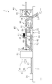
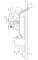
図1および図2に示すように、本実施形態は、熱交換器の製造装置(1)に関し、熱交換器は、例えばヒートポンプ式の給湯装置等に用いられる水熱交換器を構成している。
上記製造装置(1)は、3本の巻管(3)と、芯管(2)と、該芯管(2)を周方向に回転させる芯管回転機構(10)と、上記芯管(2)をその軸方向に移動させる芯管移動機構(20)と、上記芯管(2)に対して突起を形成する芯管加工機構(60)と、上記芯管(2)に巻管(3)を巻き付ける巻付機構(90)と、上記芯管(2)および巻管(3)を加熱させる加熱機構(30)と、上記芯管(2)および巻管(3)に半田を供給する半田供給装置(40)と、位置調節部(80)とを備えている。上記製造装置(1)は、作業台(5)上に設置されている。上記芯管回転機構(10)及び芯管移動機構(20)は、移動機構(6)を構成している。
上記芯管(2)は、円筒体に形成された直線状の銅製の管であり、その内部に水が流通する水通路を形成している。上記製造装置(1)において芯管(2)は、その軸方向が左右方向となる状態に設置されている。
上記巻管(3)は、芯管(2)より小径の円筒体に形成された銅製の管である。この巻管(3)は、芯管(2)の外表面に螺旋状に巻かれ、その内部に冷媒が流通する冷媒通路を形成している。そして、上記巻管(3)は、芯管(2)に3条の螺旋状を形成するように巻き付けられている。また、螺旋状に巻き付けられた各巻管(3)は、それぞれのリードが互いに等しくなっている。上記水熱交換器は、巻管(3)内を流通する冷媒と芯管(2)内を流通する水の間で熱交換を行うように構成されている。
上記芯管加工機構(60)は、上記芯管(2)の外表面に複数の突起を形成する突起形成手段を構成している。つまり、芯管加工機構(60)は、いわゆるディンプル加工を施すものである。芯管加工機構(60)は、図3および図4に示すように、ハウジング(61)と、加工ギア(62)と、該加工ギア(62)を回転駆動させる加工モータ(63)とを備えている。
上記ハウジング(61)は、上記加工モータ(63)が取り付けられるものである。ハウジング(61)は、中空で縦長の箱体に形成され、その内部の左右方向に芯管(2)が挿通されている。
上記加工モータ(63)は、上記加工ギア(62)を回転駆動させるものである。上記加工モータ(63)は、ハウジング(61)の前後方向の両側に一つずつ取り付けられ、駆動軸(64)を介して加工ギア(62)と連結されている。
上記加工ギア(62)は、上記芯管(2)の外表面に複数のディンプルを形成するものである。上記加工ギア(62)は、複数の歯が設けられた歯車であり、加工モータ(63)の駆動軸(64)に回転可能に取り付けられている。また、上記加工ギア(62)は、芯管(2)に巻き付けられた巻管(3)の螺旋形状に合わせて斜めに取り付けられている。そして、上記加工ギア(62)の歯は、芯管(2)の外表面に接触し且つ芯管(2)の移動に伴って加工ギア(62)を回転させることにより、芯管(2)の外表面に複数のディンプルを連続形成する。
上記巻付機構(90)は、上記芯管(2)に巻管(3)を螺旋状に巻き付ける巻付手段を構成している。上記巻付機構(90)は、芯管加工機構(60)に対して芯管(2)の移動方向の前側(図1における左側)に隣接している。上記巻付機構(90)は、その内部が芯管(2)よりもやや大径の内径を有する円筒体の金型部材(91)を備え、上記ハウジング(61)の側部に固定されている。そして、上記金型部材(91)は、その軸方向の中央から終端(図1において左側)にかけて巻管(3)を巻き付けるための螺旋溝が形成されている。該螺旋溝は、金型部材(91)の外周面から内周面に貫通し、上記螺旋溝の巻管(3)は、芯管(2)の外周面に接して巻き付けられる。さらに、上記巻付機構(90)は、巻管(3)に所定の張力を作用させているので、上記螺旋溝の巻管(3)は、芯管(2)の外周面に密着して巻き付けられる。
したがって、上記巻付機構(90)は、芯管(2)の一端部を金型部材(91)に挿通させ且つ巻管(3)を螺旋溝に沿って芯管(2)に押し付けた状態で芯管(2)をその周方向に回転させると、巻管(3)が芯管(2)に螺旋状に巻付くように構成されている。また、上記巻付機構(90)は、巻管(3)を螺旋溝に沿って芯管(2)に密着させているので、ネジと同様に、芯管(2)にその軸方向の始端側から終端側に向かう駆動力が付与されるように構成されている。つまり、上記巻付機構(90)は、巻管(3)を芯管(2)に巻き付けると共に、芯管(2)をその軸方向へ移動させる移動手段を兼ねており、芯管(2)が一回転する間の軸方向への移動量を調節している。
上記芯管回転機構(10)は、上記芯管(2)をその周方向に回転させるものであって、回転機構を構成している。上記芯管回転機構(10)は、内部に回転モータ(図示なし)を有するケーシング(11)と、上記芯管(2)の端部(開端側)を掴むチャック部(12)とを備えている。上記回転モータとチャック部(12)とは連結されているので、回転モータの回転に伴ってチャック部(12)がその周方向に回転し、芯管(2)がその周方向に回転する。
上記芯管移動機構(20)は、上記芯管回転機構(10)を芯管(2)の軸方向に移動させるように構成されている。上記芯管移動機構(20)は、ネジ溝の形成された軸部材(21)と、該軸部材(21)を周方向に回転させる芯管送りモータ(22)とを備え、いわゆるネジ送り機構に構成されている。上記芯管移動機構(20)は、芯管送りモータ(22)を回転させることにより、ケーシング(11)が移動すると共に、チャック部(12)に取り付けられた芯管(2)を軸方向にやや引っ張るように構成され、芯管(2)の軸方向移動を補助している。上記芯管移動機構(20)は、芯管(2)が一回転する間の軸方向への移動量が螺旋状となった各巻管(3)のリードと一致するよう芯管回転機構(10)の移動量を調節している。
上記加熱機構(30)は、芯管(2)および巻管(3)を加熱する加熱手段を構成している。上記加熱機構(30)は、巻付機構(90)より芯管(2)の移動方向の前側(図1における左側)に隣接している。上記加熱機構(30)は、燃焼用のガスが噴出する噴出部(31)と、噴出部(31)から噴出するガス流量を調節するガス制御部(32)と、芯管(2)および巻管(3)の表面温度を計測するワーク温度検出部(33)とを備えている。
上記噴出部(31)は、先端から燃焼用のガスが噴出するノズルに形成され、上記芯管移動機構(20)の軸部材(21)の中央部よりやや先端側(図2の右側)に設けられ、下側から芯管(2)および巻管(3)を加熱するようにしている。
上記ワーク温度検出部(33)は、非接触式の温度センサーによって構成され、噴出部(31)に隣接して設けられてワーク温度計測手段を構成している。上記ワーク温度検出部(33)は、芯管(2)および巻管(3)のうち加熱された部分の表面温度を計測している。ここで、計測した温度データはガス制御部(32)に送られる。尚、上記ワーク温度検出部(33)は、赤外線放射温度計やサーモグラフを用いてもよい。
上記ガス制御部(32)は、噴出部(31)から噴出させるガス流量を調節する温度調節手段を構成している。つまり、上記ガス制御部(32)は、加熱機構(30)の加熱量を制御している。上記ガス制御部(32)は、ワーク温度検出部(33)と噴出部(31)に接続され、ワーク温度検出部(33)から送られてくる温度データに基づいて噴出部(31)から噴出させるガス流量を調節するよう構成されている。
上記半田供給装置(40)は、芯管(2)と巻管(3)の間に半田を供給するものであるいる。半田供給装置(40)は、加熱機構(30)に隣接し且つ加熱機構(30)より芯管(2)および巻管(3)の軸方向の移動方向の前側(図1における左側)に配置されている。上記半田供給装置(40)は、3つの半田供給機構(41)と、該半田供給機構(41)を移動させる半田移動機構(50)と、架台(54)と、エアシリンダ(48)と、ガイド部材(49)とを備えている。上記半田供給機構(41)および半田移動機構(50)は、架台(54)上に設置されている。また、上記架台(54)には、エアシリンダ(48)およびガイド部材(49)が取り付けられ、エアシリンダ(48)およびガイド部材(49)によって芯管(2)の軸方向に直交する方向に移動可能に構成されている。
上記半田供給機構(41)は、芯管(2)と巻管(3)の間に半田を供給する半田供給手段を構成している。上記半田供給機構(41)は、後述する移動台(42)に芯管(2)の軸方向に沿って3つ設けられている。各半田供給機構(41)は、半田スプール(43)と、該半田スプール(43)に対応する半田供給ノズル(45)とが一対となって構成されている。半田供給機構(41)は、芯管(2)に巻き付けられる3本の巻管(3)のうち、一本の巻管(3)に対して一つ設けられている。
上記半田スプール(43)は、円筒体の巻軸を有し、該巻軸に線状の半田(47)が巻かれて形成されている。半田スプール(43)は、移動台(42)に芯管(2)の軸方向に沿って3つ並べて設置されている。
上記半田供給ノズル(45)は、上記半田スプール(43)から送られた線状の半田(47)を芯管(2)と巻管(3)の間に供給するものである。上記半田供給ノズル(45)は、細管のノズルに形成され、その内部に線状の半田(47)を挿通している。上記半田供給ノズル(45)は、半田スプール(43)よりも芯管(2)側に芯管(2)の軸方向に沿って3つ並べて設けられ、各半田供給ノズル(45)の先端は、巻管(3)と芯管(2)の間に向けられている。
上記半田移動機構(50)は、上記半田供給機構(41)を芯管(2)および巻管(3)に対して移動させるものである。上記半田移動機構(50)は、上記半田供給機構(41)を移動させる移動台(42)と、一端が端部部材(53)に支持された半田軸部材(51)と、該半田軸部材(51)の他端に取り付けられた半田送りモータ(52)とを備え、いわゆるネジ送り機構を構成している。
上記半田軸部材(51)は、上記移動台(42)の移動によって半田供給機構(41)を上記芯管(2)および巻管(3)に沿って移動させるものである。上記半田軸部材(51)は、細長の円筒体に形成され、その表面にネジ溝が形成されている。上記半田軸部材(51)は、一端が端部部材(53)に支持され、芯管(2)の軸方向に平行に設置されている。一方、上記半田軸部材(51)の他端は、後述する半田送りモータ(52)が取り付けられている。また、上記半田軸部材(51)の軸方向の中央部には、移動台(42)が移動可能に取り付けられている。
上記移動台(42)は、矩形の箱体に形成され、上記半田供給機構(41)の下部の上記半田軸部材(51)に取り付けられている。上記移動台(42)には、半田スプール(43)がスプール取付部(44)を介して取り付けられる一方、半田供給ノズル(45)がノズル取付部(46)を介して取り付けられている。
上記半田送りモータ(52)は、半田軸部材(51)を周方向に回転させるものである。上記半田送りモータ(52)は、半田軸部材(51)の端部に取り付けられ、その駆動軸が半田軸部材(51)に連結されている。つまり、上記半田送りモータ(52)が回転駆動すると、その駆動が半田軸部材(51)に伝わり、半田軸部材(51)がその周方向に回転する。そして、上記半田軸部材(51)が回転すると、半田軸部材(51)に取り付けられた移動台(42)が、半田軸部材(51)の螺旋形状に送られて移動する。したがって、半田送りモータ(52)を回転させることで、移動台(42)が移動すると共に、半田供給機構(41)を芯管(2)の軸方向に沿って移動する。
上記エアシリンダ(48)は、架台(54)に取り付けられており、半田供給機構(41)、移動台(42)および半田移動機構(50)を、芯管(2)の軸方向の直交方向に移動させるものである。
上記ガイド部材(49)は、架台(54)の両端側に取り付けられている。エアシリンダ(48)によって架台(54)が移動する際、該架台(54)は、ガイド部材(49)に案内されて移動することになる。
上記位置調節部(80)は、芯管(2)に巻き付けられた巻管(3)の位置を検出し、検出結果に基づいて半田供給機構(41)の位置を調節するものである。位置調節部(80)は、位置検出部(81)と、コントローラ(82)とを備えている。
上記位置検出部(81)は、非接触式のレーザー変位計によって構成され、半田供給機構(41)に隣接し且つ該半田供給機構(41)より芯管(2)の移動方向の後側(図1において右側)に設けられて位置検出手段を構成している。上記位置検出部(81)は、芯管(2)および巻管(3)に近傍に配置され、芯管(2)に巻き付けられた巻管(3)の位置を計測している。計測された巻管(3)の位置データは、後述するコントローラ(82)に送られる。尚、レーザー変位計は、接触式の変位計を用いてもよい。
上記コントローラ(82)は、上記位置検出部(81)から送られた巻管(3)の位置データに基づいて半田供給機構(41)の位置を調節する制御手段を構成している。具体的には、上記コントローラ(82)は、位置検出部(81)から送られた巻管(3)の位置データに基づいて該巻管(3)の所定位置からのずれ量に対応する分だけ半田送りモータ(52)を回転させて半田供給機構(41)を移動させる。これにより、上記半田供給機構(41)が巻管(3)のずれ量だけ移動することになるため、芯管(2)と巻管(3)の間に確実に半田を供給することができる。
-熱交換器の製造方法-
次に、熱交換器の製造装置(1)の製造動作について製造方法と共に説明する。
次に、熱交換器の製造装置(1)の製造動作について製造方法と共に説明する。
まず、ケーシング(11)は、芯管移動機構(20)における先端側に移動させる一方、架台(54)は、エアシリンダ(48)とガイド部材(49)により、芯管(2)から半田供給ノズル(45)を遠ざける方向へ移動させる。そして、芯管(2)の先端部を芯管加工機構(60)および巻付機構(90)を介して芯管回転機構(10)のチャック部(12)に取り付ける。そして、巻付機構(90)は、3本の巻管(3)を螺旋溝に沿って芯管(2)に所定の張力により密着させる。この状態で、回転モータ、芯管送りモータ(22)および加工モータ(63)を駆動させる。回転モータが駆動するとチャック部(12)が回転して芯管(2)が周方向に回転する。芯管送りモータ(22)が駆動すると、軸部材(21)が回転して芯管(2)が始端側から終端側に向かって移動し始める。つまり、芯管(2)はその周方向に回転しつつ、その軸方向の始端側から終端側に向かって移動する。
次に、突起形成工程に移る。突起形成工程では、芯管(2)の軸方向および周方向の移動に合わせて加工ギア(62)が回転する。そして、加工ギア(62)の歯が芯管(2)の外表面にディンプルを形成する。
続いて、巻付工程に移る。巻付工程では、芯管(2)のうちディンプルの形成された部分に巻管(3)が巻き付けられる。巻付工程では、回転モータを駆動させて芯管(2)が回転すると、巻管(3)が芯管(2)に螺旋状に巻き付いてゆく。このとき、巻管(3)が螺旋溝に沿って芯管(2)に押し付けられることで、芯管(2)に対して、その軸方向の始端側から終端側に向かう駆動力が付与され、芯管(2)がその軸方向の始端側から終端側に移動する。このとき、芯管(2)がその軸方向の終端側から始端側に向かって移動する際、位置検出部(81)が芯管(2)に巻き付いた巻管(3)の位置を計測する。計測した位置データは、コントローラ(82)に送られて後述する位置調節動作の制御に用いられる。尚、上記計測は接合工程が終了するまで継続して行われる。
続いて、加熱工程に移る。加熱工程では、芯管(2)のうち巻付工程で巻管(3)が巻き付けられた直後の部分が加熱される。この加熱工程では、加熱機構(30)の噴出部(31)から出る火炎によって芯管(2)および巻管(3)の一部分を加熱する。芯管(2)および巻管(3)のうち加熱された部分は、芯管(2)の周方向に回転しながら、芯管(2)の軸方向の終端側に向かって移動する。
ここで、巻付工程と加熱工程を経て、加熱された芯管(2)及び巻管(3)が十分延伸し、ケーシング(11)が架台(54)の移動に干渉しない位置まで移動すると、エアシリンダ(48)とガイド部材(49)により架台(54)が半田供給ノズル(45)を加熱された芯管(2)と巻管(3)に接近させる方向に移動し、接合工程に移る。
次に、接合工程では、まず、芯管(2)および巻管(3)のうち加熱工程において加熱された部分の芯管(2)と巻管(3)の間に半田を供給する。接合工程では、芯管(2)に巻き付いた巻管(3)に対し、それぞれの巻管(3)に対応する半田供給ノズル(45)によって半田が供給される。具体的には、半田供給ノズル(45)の先端から芯管(2)と巻管(3)の間に半田が供給される。ここで、巻管(3)は、芯管(2)に対して螺旋状に巻かれている一方で、該巻管(3)の螺旋形状に対応するように芯管(2)および巻管(3)は芯管(2)の周方向に回転しつつ、芯管(2)の軸方向に移動している。このため、半田供給ノズル(45)の先端は螺旋形状の巻管(3)に対して移動することなく、半田を供給することができる。尚、接合工程において芯管(2)と巻管(3)の間に半田を供給する際、ワーク温度検出部(33)が芯管(2)および巻管(3)のうち加熱工程において加熱された部分の芯管(2)および巻管(3)の表面温度を計測する。計測した温度データは、ガス制御部(32)に送られて後述する温度調節動作の制御に用いられる。尚、上記計測は接合工程が終了するまで継続して行われる。
ここで、接合工程において半田供給機構(41)の半田供給ノズル(45)の先端を芯管(2)に巻き付けられた巻管(3)に倣わせる位置調節動作について説明する。上記位置検出部(81)によって計測された巻管(3)の位置データにずれが生じた場合、コントローラ(82)は、巻管(3)のずれ量に応じて半田送りモータ(52)を駆動させて、半田供給機構(41)を移動させる。これにより、半田供給ノズル(45)の先端位置を巻管(3)に合わせて調節する。
また、接合工程において加熱機構(30)の温度制御について説明する。上記ワーク温度検出部(33)によって計測された芯管(2)および巻管(3)の温度データがガス制御部(32)に送られる。送られた温度データに基づいて芯管(2)および巻管(3)の温度が所定の温度になるようにガス制御部(32)が噴出部(31)から噴出するガスの流量を調節する。これにより、芯管(2)および巻管(3)が所定の温度に保たれる。
その後、ケーシング(11)を軸部材(21)の終端まで移動して、全ての巻管(3)と芯管(2)の間に半田を供給する。そして、供給した半田を冷却して芯管(2)と巻管(3)を半田接合する。尚、半田が完全に固形化すると、芯管(2)および巻管(3)を所定形状に折曲げて熱交換器を製造する。
-実施形態の効果-
上記本実施形態は、巻管(3)を芯管(2)に巻き付けた直後に、芯管(2)および巻管(3)の一部分を加熱し、加熱されて高温となった芯管(2)と巻管(3)の間へ半田を供給している。つまり、上記巻管(3)を芯管(2)に巻き付けた直後であるため、芯管(2)に巻管(3)が密着している状態で、芯管(2)と巻管(3)を半田で接合することができる。したがって、本実施形態によれば、上記巻管(3)を芯管(2)に巻き付けてから、時間をおいて芯管(2)と巻管(3)を接合する従来技術に比べ、芯管(2)と巻管(3)の密着性を向上させることができる。この結果、熱交換器の熱伝達率を向上させることができる。
上記本実施形態は、巻管(3)を芯管(2)に巻き付けた直後に、芯管(2)および巻管(3)の一部分を加熱し、加熱されて高温となった芯管(2)と巻管(3)の間へ半田を供給している。つまり、上記巻管(3)を芯管(2)に巻き付けた直後であるため、芯管(2)に巻管(3)が密着している状態で、芯管(2)と巻管(3)を半田で接合することができる。したがって、本実施形態によれば、上記巻管(3)を芯管(2)に巻き付けてから、時間をおいて芯管(2)と巻管(3)を接合する従来技術に比べ、芯管(2)と巻管(3)の密着性を向上させることができる。この結果、熱交換器の熱伝達率を向上させることができる。
また、上記芯管(2)に巻き付けられた巻管(3)の位置を検出し、検出された巻管(3)の位置に対応して半田供給機構(41)の位置を調節するようにしたため、芯管(2)に巻かれた巻管(3)の位置がずれても、半田供給機構(41)の位置を調節することで、芯管(2)と巻管(3)の間に確実に半田を供給することができる。
また、上記ワーク温度検出部(33)によって計測された芯管(2)および巻管(3)の温度に基づいて加熱機構(30)のガス流量を調節するようにしたため、芯管(2)および巻管(3)の温度を所望の温度に保つことができる。
〈本実施形態の変形例〉
次に、本実施形態の変形例について図面に基づいて説明する。
次に、本実施形態の変形例について図面に基づいて説明する。
本変形例は、本実施形態における位置調節部(80)が、非接触式のレーザー変位計からなる位置検出部(81)を備えていたのに代えて、図5および図6に示すように、接触式の位置検出部(81)を備えるようにしたものである。また、半田供給装置(40)において全ての半田供給機構(41)を芯管(2)に沿って移動させていたのに代えて、各半田供給機構(41)毎に移動させるようにしたものである。
具体的に、上記半田供給装置(40)は、半田供給機構(41)と、半田移動機構(84)を備えている。
上記半田移動機構(84)は、芯管(2)に平行に設置される半田軸部材(85)と、該半田軸部材(85)を回転させる半田送りモータ(86)とで構成されている。半田送りモータ(86)を駆動させると、半田軸部材(85)がその周方向に回転することで、半田供給機構(41)を芯管(2)の軸方向に沿って移動させることができる。
また、上記位置調節部(80)において、上記位置検出部(81)は、接触圧検知センサに形成され、上記ノズル取付部(46)に取り付けられている。位置検出部(81)の先端(81a)は、芯管(2)に巻き付けられた巻管(3)に接触し、芯管(2)と巻管(3)の接合点付近における巻管(3)の位置を計測している。計測された巻管(3)の位置データはコントローラ(82)に送られる。該コントローラ(82)は、送られた位置データに基づいて上記半田送りモータ(86)を駆動させて半田供給機構(41)を芯管(2)の軸方向に沿って移動させる。これにより、半田供給ノズル(45)の先端位置を巻管(3)に合わせて調節することができる。その他の構成および動作については実施形態と同様である。
〈その他の実施形態〉
本発明は、上記実施形態について、以下のような構成としてもよい。
本発明は、上記実施形態について、以下のような構成としてもよい。
本実施形態に係る熱交換器の製造装置(1)において、芯管(2)および巻管(3)の温度を計測し、この温度データに基づいて、加熱機構(30)のガス流量を制御するようにしたが、本発明は、図7に示すように、室温計測用の周囲温度計測部(34)を用いて芯管(2)および巻管(3)の周囲の温度を計測し、該周囲温度データに基づいて加熱機構(30)のガス流量を制御するようにしてもよい。上記周囲温度計測部(34)は、本発明に係る周囲温度計測手段を構成している。
また、本実施形態に係る熱交換器の製造装置(1)において、加熱手段として火炎を用いたが、本発明は、加熱手段として高周波発生装置又は赤外線加熱装置を用いてもよい。この場合、高周波発生装置は、高周波の入力値を段階的に変えることで、加熱量を調節する。したがって、芯管(2)および巻管(3)の温度を計測し、この温度データに基づいて、高周波発生装置の入力値を制御するようにしてもよい。また、芯管(2)および巻管(3)の周囲の温度を計測し、該周囲温度データに基づいて高周波発生装置の入力値を制御するようにしてもよい。また、加熱手段として加熱ヒータを用いてもよい。この場合、加熱ヒータは、高周波の入力値を段階的に変えることで加熱量を調節する。したがって、芯管(2)および巻管(3)の温度を計測し、この温度データに基づいて加熱ヒータの入力値を制御するようにしてもよい。また、芯管(2)および巻管(3)の周囲の温度を計測し、該周囲温度データに基づいて加熱ヒータの入力値を制御するようにしてもよい。
尚、以上の実施形態は、本質的に好ましい例示であって、本発明、その適用物、あるいはその用途の範囲を制限することを意図するものではない。
以上説明したように、本発明は、熱交換器の製造装置および製造方法について有用である。
2 芯管
3 巻管
20 芯管移動機構
30 加熱機構
32 ガス制御部
33 ワーク温度検出部
34 周囲温度計測部
41 半田供給機構
81 位置検出部
82 コントローラ
90 巻付機構
3 巻管
20 芯管移動機構
30 加熱機構
32 ガス制御部
33 ワーク温度検出部
34 周囲温度計測部
41 半田供給機構
81 位置検出部
82 コントローラ
90 巻付機構
Claims (10)
- 芯管(2)内を流れる流体と該芯管(2)に螺旋状に巻き付けられた巻管(3)内を流れる流体とを熱交換させる熱交換器の製造装置であって、
直管状に形成された上記芯管(2)の軸方向に移動自在に構成され、上記芯管(2)を周方向へ回転させる回転機構(10)と、
該回転機構(10)によって回転させられている上記芯管(2)に上記巻管(3)を螺旋状に巻き付ける巻付機構(90)と、
上記芯管(2)のうち巻管(3)が巻き付けられた部分の一部分を加熱する加熱機構(30)と、
該加熱機構(30)によって加熱された芯管(2)と巻管(3)の間へ半田を供給する半田供給機構(41)とを備えている
ことを特徴とする熱交換器の製造装置。 - 請求項1において、
上記芯管(2)に該芯管(2)の内周面側へ突出する突起を形成する突起形成機構(60)を備えている
ことを特徴とする熱交換器の製造装置。 - 請求項1において、
上記巻付機構(90)は、巻管(3)を螺旋状に塑性変形させて上記回転機構(10)によって回転駆動する芯管(2)の外周面に巻き付ける金型部材(91)を備え、上記芯管(2)に巻管(3)を巻き付けることによって上記芯管(2)に該芯管(2)の軸方向の駆動力を付与するように構成されている
ことを特徴とする熱交換器の製造装置。 - 請求項1において、
上記半田供給機構(41)は、上記芯管(2)に対して移動可能に構成され、
上記芯管(2)に巻かれた巻管(3)の位置を検出する位置検出部(81)と、該位置検出部(81)が検出した巻管(3)の位置に基づいて半田供給機構(41)の位置を制御する制御部(82)とを備えている
ことを特徴とする熱交換器の製造装置。 - 請求項1において、
上記加熱機構(30)は、上記芯管(2)および巻管(3)の温度を調節するための温度調節部(32)を備えている
ことを特徴とする熱交換器の製造装置。 - 請求項5において、
上記温度調節部(32)は、上記加熱機構(30)の加熱量を調節することによって芯管(2)および巻管(3)の温度を調節するように構成されている
ことを特徴とする熱交換器の製造装置。 - 請求項6において、
上記加熱機構(30)は、上記加熱された芯管(2)および巻管(3)の温度を計測するワーク温度計測部(33)を備え、
上記温度調節部(32)は、上記ワーク温度計測部(33)の計測値に基づいて上記加熱機構(30)の加熱量を調節するように構成されている
ことを特徴とする熱交換器の製造装置。 - 請求項6において、
上記加熱機構(30)は、上記芯管(2)および巻管(3)の周囲の温度を計測する周囲温度計測部(34)を備え、
上記温度調節部(32)は、上記周囲温度計測部(34)の計測値に基づいて上記加熱機構(30)の加熱量を調節するように構成されている
ことを特徴とする熱交換器の製造装置。 - 芯管(2)内を流れる流体と該芯管(2)に螺旋状に巻き付けられた巻管(3)内を流れる流体とを熱交換させる熱交換器の製造方法であって、
周方向に回転している直管状の芯管(2)に巻管(3)を螺旋状に巻き付け、上記芯管(2)を軸方向に移動させる巻付工程と、
該巻付工程において巻管(3)が巻き付けられた芯管(2)のうち巻管(3)が巻き付けられた部分の一部分を加熱する加熱工程と、
該加熱工程において加熱された芯管(2)と巻管(3)の間へ半田を供給して芯管(2)と巻管(3)を接合する接合工程とを備えている
ことを特徴とする熱交換器の製造方法。 - 請求項9において、
上記芯管(2)のうち巻管(3)が巻き付けられる前の部分の外周面を押圧し、上記芯管(2)に該芯管(2)の内周面側へ突出する突起を形成する突起形成工程を備えている
ことを特徴とする熱交換器の製造方法。
Applications Claiming Priority (2)
| Application Number | Priority Date | Filing Date | Title |
|---|---|---|---|
| JP2010-086164 | 2010-04-02 | ||
| JP2010086164 | 2010-04-02 |
Publications (1)
| Publication Number | Publication Date |
|---|---|
| WO2011125324A1 true WO2011125324A1 (ja) | 2011-10-13 |
Family
ID=44762295
Family Applications (1)
| Application Number | Title | Priority Date | Filing Date |
|---|---|---|---|
| PCT/JP2011/002012 Ceased WO2011125324A1 (ja) | 2010-04-02 | 2011-04-04 | 熱交換器の製造装置および製造方法 |
Country Status (2)
| Country | Link |
|---|---|
| JP (1) | JP4775517B1 (ja) |
| WO (1) | WO2011125324A1 (ja) |
Families Citing this family (7)
| Publication number | Priority date | Publication date | Assignee | Title |
|---|---|---|---|---|
| WO2013094249A1 (ja) * | 2011-12-22 | 2013-06-27 | 株式会社住軽伸銅 | 熱交換器の製造方法及びそれによって得られた熱交換器 |
| JP6070187B2 (ja) * | 2012-12-28 | 2017-02-01 | ダイキン工業株式会社 | 調湿モジュール及びそれを備えた調湿装置 |
| WO2017220210A1 (de) * | 2016-06-21 | 2017-12-28 | Linde Aktiengesellschaft | Definition der vorspannung der rohre beim wickeln eines rohrbündels eines gewickelten wärmeübertragers |
| US11569011B2 (en) * | 2016-11-04 | 2023-01-31 | John Howard | Method and apparatus for reinforcing a cable used in high frequency applications |
| CN110303217B (zh) * | 2019-07-18 | 2021-03-26 | 湘潭大学 | 一种多机器人自动线缆焊锡装配单元 |
| JP7406069B2 (ja) * | 2019-09-26 | 2023-12-27 | ダイキン工業株式会社 | 熱交換器 |
| JPWO2021181694A1 (ja) * | 2020-03-13 | 2021-09-16 |
Citations (3)
| Publication number | Priority date | Publication date | Assignee | Title |
|---|---|---|---|---|
| JP2002011593A (ja) * | 2000-04-27 | 2002-01-15 | Mitsubishi Electric Corp | 無鉛はんだ、電子基板、家電装置、冷蔵庫、電子部品の接合方法、配管の接合方法、はんだ付け装置 |
| JP2002228370A (ja) * | 2001-01-30 | 2002-08-14 | Daikin Ind Ltd | 熱交換器 |
| JP2006317115A (ja) * | 2005-05-16 | 2006-11-24 | Daikin Ind Ltd | 熱交換器 |
-
2011
- 2011-04-04 JP JP2011082933A patent/JP4775517B1/ja active Active
- 2011-04-04 WO PCT/JP2011/002012 patent/WO2011125324A1/ja not_active Ceased
Patent Citations (3)
| Publication number | Priority date | Publication date | Assignee | Title |
|---|---|---|---|---|
| JP2002011593A (ja) * | 2000-04-27 | 2002-01-15 | Mitsubishi Electric Corp | 無鉛はんだ、電子基板、家電装置、冷蔵庫、電子部品の接合方法、配管の接合方法、はんだ付け装置 |
| JP2002228370A (ja) * | 2001-01-30 | 2002-08-14 | Daikin Ind Ltd | 熱交換器 |
| JP2006317115A (ja) * | 2005-05-16 | 2006-11-24 | Daikin Ind Ltd | 熱交換器 |
Also Published As
| Publication number | Publication date |
|---|---|
| JP4775517B1 (ja) | 2011-09-21 |
| JP2011224657A (ja) | 2011-11-10 |
Similar Documents
| Publication | Publication Date | Title |
|---|---|---|
| JP4775517B1 (ja) | 熱交換器の製造装置および製造方法 | |
| CN102554401B (zh) | 一种炼钢用氧枪铜端头与钢质管短节焊接方法 | |
| CN112848240A (zh) | 一种螺旋管缠绕装置 | |
| US12521814B2 (en) | Solid state additive method | |
| CN108908931A (zh) | 一种3d打印丝材熔接设备 | |
| CN101244482A (zh) | 一种合金锯片的焊接方法及采用该方法的焊齿机 | |
| CN113245658B (zh) | 一种可预热可注射的焊锡工具 | |
| US20090301159A1 (en) | Method of forming, inserting and permanently bonding ribs in boiler tubes | |
| CN101644366A (zh) | 弹簧伸缩管内外层塑料的熔接方法 | |
| JP5411542B2 (ja) | 溶接装置 | |
| JP5903444B2 (ja) | 熱交換器の製造方法及びそれによって得られた熱交換器 | |
| US12397360B2 (en) | Brazing probe | |
| CN220499936U (zh) | 一种空心管扩口设备 | |
| CN116984692A (zh) | 一种印刷电路板高精密焊接设置及工艺 | |
| KR200400924Y1 (ko) | 고주파 용접장치 | |
| JP3734438B2 (ja) | たわみ管の製造方法およびその装置 | |
| JP2011212742A (ja) | 接合装置および熱交換器の製造方法 | |
| CN214348941U (zh) | 一种旋压成型加热系统 | |
| JP3456112B2 (ja) | ハンダコテの温度測定方法およびハンダ付け装置 | |
| JP5180174B2 (ja) | 積層型熱交換器、及び積層型熱交換器の製造方法 | |
| JP5983491B2 (ja) | スパイラルフィン型熱交換器の製造方法および製造装置 | |
| JP5421582B2 (ja) | 溶接装置 | |
| CN87102675A (zh) | 以套筒连接绝热导管时调节焊接过程的方法 | |
| KR100877713B1 (ko) | 전열관 제조방법 및 그 제조장치 | |
| CN119703322B (zh) | 一种采用电磁预加热的手持便携式搅拌摩擦焊接设备及焊接方法 |
Legal Events
| Date | Code | Title | Description |
|---|---|---|---|
| 121 | Ep: the epo has been informed by wipo that ep was designated in this application |
Ref document number: 11765226 Country of ref document: EP Kind code of ref document: A1 |
|
| NENP | Non-entry into the national phase |
Ref country code: DE |
|
| 122 | Ep: pct application non-entry in european phase |
Ref document number: 11765226 Country of ref document: EP Kind code of ref document: A1 |