WO2011125283A1 - X線透視撮影装置 - Google Patents
X線透視撮影装置 Download PDFInfo
- Publication number
- WO2011125283A1 WO2011125283A1 PCT/JP2011/001218 JP2011001218W WO2011125283A1 WO 2011125283 A1 WO2011125283 A1 WO 2011125283A1 JP 2011001218 W JP2011001218 W JP 2011001218W WO 2011125283 A1 WO2011125283 A1 WO 2011125283A1
- Authority
- WO
- WIPO (PCT)
- Prior art keywords
- position information
- installation
- command
- rotation
- fluoroscopic imaging
- Prior art date
Links
Images


Classifications
-
- A—HUMAN NECESSITIES
- A61—MEDICAL OR VETERINARY SCIENCE; HYGIENE
- A61B—DIAGNOSIS; SURGERY; IDENTIFICATION
- A61B6/00—Apparatus for radiation diagnosis, e.g. combined with radiation therapy equipment
- A61B6/44—Constructional features of apparatus for radiation diagnosis
- A61B6/4429—Constructional features of apparatus for radiation diagnosis related to the mounting of source units and detector units
- A61B6/4435—Constructional features of apparatus for radiation diagnosis related to the mounting of source units and detector units the source unit and the detector unit being coupled by a rigid structure
- A61B6/4441—Constructional features of apparatus for radiation diagnosis related to the mounting of source units and detector units the source unit and the detector unit being coupled by a rigid structure the rigid structure being a C-arm or U-arm
-
- A—HUMAN NECESSITIES
- A61—MEDICAL OR VETERINARY SCIENCE; HYGIENE
- A61B—DIAGNOSIS; SURGERY; IDENTIFICATION
- A61B6/00—Apparatus for radiation diagnosis, e.g. combined with radiation therapy equipment
- A61B6/46—Apparatus for radiation diagnosis, e.g. combined with radiation therapy equipment with special arrangements for interfacing with the operator or the patient
- A61B6/467—Apparatus for radiation diagnosis, e.g. combined with radiation therapy equipment with special arrangements for interfacing with the operator or the patient characterised by special input means
-
- A—HUMAN NECESSITIES
- A61—MEDICAL OR VETERINARY SCIENCE; HYGIENE
- A61B—DIAGNOSIS; SURGERY; IDENTIFICATION
- A61B6/00—Apparatus for radiation diagnosis, e.g. combined with radiation therapy equipment
- A61B6/54—Control of apparatus or devices for radiation diagnosis
- A61B6/547—Control of apparatus or devices for radiation diagnosis involving tracking of position of the device or parts of the device
-
- A—HUMAN NECESSITIES
- A61—MEDICAL OR VETERINARY SCIENCE; HYGIENE
- A61B—DIAGNOSIS; SURGERY; IDENTIFICATION
- A61B6/00—Apparatus for radiation diagnosis, e.g. combined with radiation therapy equipment
- A61B6/10—Application or adaptation of safety means
- A61B6/102—Protection against mechanical damage, e.g. anti-collision devices
-
- A—HUMAN NECESSITIES
- A61—MEDICAL OR VETERINARY SCIENCE; HYGIENE
- A61B—DIAGNOSIS; SURGERY; IDENTIFICATION
- A61B6/00—Apparatus for radiation diagnosis, e.g. combined with radiation therapy equipment
- A61B6/44—Constructional features of apparatus for radiation diagnosis
- A61B6/4429—Constructional features of apparatus for radiation diagnosis related to the mounting of source units and detector units
- A61B6/4464—Constructional features of apparatus for radiation diagnosis related to the mounting of source units and detector units the source unit or the detector unit being mounted to ceiling
-
- A—HUMAN NECESSITIES
- A61—MEDICAL OR VETERINARY SCIENCE; HYGIENE
- A61B—DIAGNOSIS; SURGERY; IDENTIFICATION
- A61B6/00—Apparatus for radiation diagnosis, e.g. combined with radiation therapy equipment
- A61B6/48—Diagnostic techniques
- A61B6/485—Diagnostic techniques involving fluorescence X-ray imaging
Definitions
- the present invention relates to an X-ray fluoroscopic apparatus provided with a fluoroscopic imaging system, and more particularly to a technique for smoothly moving the fluoroscopic imaging system.
- an X-ray tube and an X-ray detector are supported so as to face each other, and a fluoroscopic imaging system configured by support means that can rotate and translate with respect to a subject lying on a bed.
- a fluoroscopic imaging system configured by support means that can rotate and translate with respect to a subject lying on a bed.
- the support means is rotated in the body axis direction and around the body axis of the subject by a driving mechanism disposed in the operating unit, and is translated in the longitudinal direction, the short direction, the height direction, and the like of the top plate.
- a position detector is connected to the drive mechanism, and position information such as the rotation direction and rotation angle of the support means, the longitudinal direction, the short direction, and the height is detected. Based on the detected position information, the operator can move the support means to a desired position. Further, the ROI coordinates can be stored in a state in which the region of interest of the subject is matched with the ROIs of the two fluoroscopic imaging systems.
- the support means performs a target rotation when X-ray irradiation is performed on a plurality of memory switches associated with the rotation direction and rotation angle of the support means.
- Japanese Patent Laying-Open No. 2005-245814 page 4-8, FIG. 1) JP-A-8-150137 (page 3-6, FIGS. 4 and 15)
- the conventional example having such a configuration has the following problems. That is, when the conventional apparatus moves the fluoroscopic imaging system from the standby position in the examination room to the target rotation position, the operation of installing the fluoroscopic imaging system from the standby position to the fluoroscopic imaging area is performed, and then There is a problem in that it is necessary to perform two operations of moving the fluoroscopic imaging system from the installation position to the target rotational position, and a quick inspection cannot be performed.
- the present invention has been made in view of such circumstances, and provides an X-ray fluoroscopic imaging apparatus capable of smoothly moving a fluoroscopic imaging system from a standby position via an installation position to a target rotation position.
- the purpose is to do.
- the present invention has the following configuration. That is, the present invention is an X-ray fluoroscopic apparatus that performs X-ray fluoroscopy from multiple directions of a subject, and supports an X-ray tube and an X-ray detector facing each other and lies on a bed lying on a bed.
- a fluoroscopic imaging system comprising support means that can rotate and translate, position detection means for detecting actual position information of the support means around the subject, and fluoroscopy capable of being installed with the support means
- Position command means for commanding installation position information associated with the area and target rotation position information associated with the target rotation position of the support means; installation position command and rotation command commanded by the position command means; A command execution means for executing a moving position command; and when the installation position command and the rotation position command are executed by the command execution means, the installation position information and the actual position information output from the position detection means
- Position control means for continuously executing control for parallel movement of the support means so as to match, and control for rotating the support means so that the target rotation position information and the actual position information match. It is characterized by comprising.
- the position command means includes the installation position information associated with the fluoroscopic imaging area where the support means is installed and the purpose associated with the target rotational position. Commands rotation position information.
- the command execution means causes the position control means to execute the installation position command and the rotation position command.
- the position control unit moves the support unit in parallel and acquires the actual position information of the support unit output from the position detection unit.
- the position control means next rotates the support means and acquires the actual position information of the support means output from the position detection means. .
- the position control means stops the movement of the support means. Therefore, the fluoroscopic imaging system can be smoothly moved from the standby position to the target position.
- the position command means uses the path between the predetermined standby position of the fluoroscopic imaging system and the fluoroscopic imaging area and the target rotation position information as the installation position information. It is preferable to command a rotation direction and a rotation angle of the fluoroscopic imaging system in the fluoroscopic imaging area.
- the fluoroscopic imaging system is translated along a path between a predetermined standby position and the fluoroscopic imaging area, and is rotated in a predetermined rotation direction and rotation angle in the fluoroscopic imaging area. Therefore, it can be smoothly moved from the standby position to a predetermined rotation direction and rotation angle.
- the position command means includes an installation memory switch associated with the installation position information and a plurality of rotation memory switches associated with the target rotation position information. And when the command execution means is commanded by both the installation memory switch and the rotation memory switch, the command execution means executes both the commands in common, and the installation memory switch and the rotation memory switch When instructed from either one of these, it is preferable that the memory execution switch execute the one of the instructions. Thereby, the operation of moving the fluoroscopic imaging system from the standby position to the target position can be performed smoothly.
- the installation memory switch, the rotation memory switch, and the memory execution switch are arranged on one operation panel. Thereby, the operator of this X-ray fluoroscopic imaging apparatus can perform an operation of moving the fluoroscopic imaging system from the standby position to the target position with few operations.
- the X-ray fluoroscopic apparatus of the present invention may include an input unit that inputs the installation position information and the target rotation position information instead of the position command unit. Thereby, even if the installation position information and the target rotation position information are not predetermined, the fluoroscopic imaging system can be moved from the standby position to the target position based on the input installation position information and the target rotation position information. it can.
- the fluoroscopic imaging system has two systems, and when the position command unit commands a multi-system installation position, the position control unit performs the installation of each system. Control for moving the support means of each system in parallel so that position information and the actual position information match, and each system so that the target rotation position information and the actual position information of each system match It is preferable to continuously execute the control for rotating the support means. As a result, even in the biplane type X-ray fluoroscopic apparatus, the fluoroscopic system can be smoothly moved from the standby position to the target position.
- the position command means includes a path between a predetermined standby position of the fluoroscopic imaging system and the fluoroscopic imaging area as the installation position information for each of the two systems, It is preferable to instruct the rotation direction and rotation angle of the fluoroscopic imaging system in the fluoroscopic imaging area as the target rotational position information for every two systems.
- the two fluoroscopic imaging systems are translated in parallel along a path between a predetermined standby position and the fluoroscopic imaging area, and a predetermined rotation direction and rotation angle in the fluoroscopic imaging area. Therefore, the two fluoroscopic imaging systems can be smoothly moved from the standby position to a predetermined rotation direction and rotation angle.
- the fluoroscopic imaging system has two systems, and when the position commanding unit instructs the installation position of a single system, the other system is already installed in the fluoroscopic imaging region.
- the position control means preferably retracts the other system from the fluoroscopic imaging area to a standby position registered in advance.
- the other system in the fluoroscopic imaging area is retracted to a pre-registered standby position.
- the position control means moves a route that is not in contact with each of the preset systems when moving the fluoroscopic system.
- the biplane fluoroscopy system moves along a route that does not contact each other, so switching operation from multi-line fluoroscopy to single-line fluoroscopy or from multi-line fluoroscopy to single-line fluoroscopy Switching operation to fluoroscopic imaging becomes easy.
- the position control means calculates relative positional relationship information of each system and the bed, and based on the calculated relative positional relationship information, It is preferable to avoid contact with at least one of the other system or the bed. This makes it possible to avoid contact between the fluoroscopic imaging systems of the pipe lane system and contact between the fluoroscopic imaging system and the bed when switching between the multiple systems and the single system.
- the position command means is associated with a memory switch for installation associated with the installation position information of either a single system or a multiple system, and a target rotational position.
- a plurality of rotation memory switches and when the command execution means is commanded from both the installation memory switch and the rotation memory switch, the command execution means executes both the commands in common, and When instructed from either one of the memory switch and the rotation memory switch, it is preferable that the memory execution switch execute the one instruction. Thereby, the operation of moving the fluoroscopic imaging system of the two systems from the standby position to the target position and the switching operation between the multiple systems and the single system can be performed smoothly.
- the installation memory switch, the rotation memory switch, and the memory execution switch are arranged on one operation panel. Thereby, the operator of this X-ray fluoroscopic imaging apparatus can perform an operation of moving the two fluoroscopic imaging systems from the standby position to the target position with a small number of operations.
- the X-ray fluoroscopic apparatus of the present invention may include an input unit that inputs the installation position information and the target rotation position information instead of the position command unit.
- an input unit that inputs the installation position information and the target rotation position information instead of the position command unit.
- one of the two systems is a fluoroscopic system capable of traveling on the ceiling with a ceiling suspension type
- the other fluoroscopic system is a floor-mounted type and a floor. It is preferable that the fluoroscopic imaging system can travel on the surface. Accordingly, the ceiling-suspended fluoroscopic imaging system and the floor-mounted fluoroscopic imaging system can be smoothly moved from the standby position to a predetermined rotation direction and rotation angle.
- the parallel movement control and the rotation control are executed in conjunction with each other, so that the fluoroscopic imaging system can be smoothly moved from the standby position to the target rotation position via the installation position. Can be moved to.
- FIG. 1 is a perspective view illustrating a schematic configuration of an X-ray fluoroscopic apparatus according to an embodiment.
- (A) is a side view explaining a front-side drive mechanism, and (b) is a side view explaining a side-side drive mechanism.
- It is a schematic block diagram which shows the control system of an apparatus. It is a perspective view which shows the schematic structure of an operation part typically. It is a schematic diagram which shows the content of memory.
- FIG. 1 is a perspective view illustrating a schematic configuration of an X-ray fluoroscopic apparatus according to an embodiment.
- Reference numeral 23 denotes a C-shaped arm that can move around the subject M lying on the bed 1.
- the C-arm 23 is rotatably supported by a base portion 21 disposed on the floor and a C-arm support portion 22 supported by the base portion 21.
- an X-ray tube 24 and a flat panel X-ray detector (hereinafter referred to as "FPD") 25 are supported in opposition so as to sandwich the front of the subject M.
- the C-arm 23, the X-ray tube 24, and the FPD 25 constitute the X-ray fluoroscopic imaging system 2 (hereinafter referred to as the front system 2).
- Reference numeral 34 denotes an ⁇ -shaped arm that can move around the subject M lying on the bed 1.
- the ⁇ -shaped arm 34 includes a rail 31 disposed on the ceiling wall, a movable base 32 supported by the rail 31, a movable rail (not shown) supported by the movable base 32, and an ⁇ -shaped supported by the movable rail.
- the arm support part 33 is supported so as to be movable.
- an X-ray tube 35 and an FPD 36 are supported so as to sandwich the temporal region of the subject M.
- the ⁇ -shaped arm 34, the X-ray tube 35, and the FPD 36 constitute an X-ray fluoroscopic imaging system 3 (hereinafter referred to as a side system 3).
- An operation panel 40 is disposed on the side edge of the bed 1.
- the front system 2 and the side system 3 correspond to the fluoroscopic imaging system of the present invention
- the C-shaped arm support portion 22 and the ⁇ -shaped arm support portion 33 correspond to the support means of the present invention.
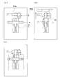
- FIG. 2A is a side view for explaining the driving mechanism of the front system 2
- FIG. 2B is a side view for explaining the driving mechanism of the side system 3.
- FIG. 2A is a side view for explaining the driving mechanism of the front system 2
- FIG. 2B is a side view for explaining the driving mechanism of the side system 3.
- the rotation of the C-arm 23 around the body axis of the subject M is realized by rotating the C-arm support portion 22 around the body axis of the subject M.
- the base of the C-shaped arm support portion 22 (the surface opposite to the surface that holds the C-shaped arm 2) is rotatably disposed on the side surface of the support column 26. Is provided.
- the gear 27 is meshed with the pinion gear 28, and the pinion gear 28 is attached to the output shaft of the drive motor M1 disposed in the support column.
- the C-arm 23 is rotated around the body axis of the subject M together with the C-arm support portion 22 by the rotating action of the drive motor M1.
- a rotary encoder D1 for detecting the rotation direction and rotation angle of the drive motor M1 is provided.
- the C-arm 22 is configured to be rotatable in the body axis direction of the subject by a driving mechanism (not shown).
- the parallel movement of the C-arm 23 is realized by a link mechanism having three rotation axes a, b, and c.
- the link mechanism moves in parallel by the rotating action of drive motors M2a, M2b, and M2c (collectively referred to as M2) disposed on the base portions 21a and 21b and the column 26.
- the drive motor M2 is connected to rotary encoders D2a, D2b, D2c (collectively referred to as a rotary encoder D2) that detect the rotation direction and rotation angle of the drive motor M2.
- the rotation of the ⁇ -shaped arm 34 around the body axis of the subject M is realized by a drive mechanism in the ⁇ -shaped arm holding unit 33.
- a part of the belt 61 (or chain) whose both ends are fixed to the ⁇ -shaped arm 34 is accommodated in the ⁇ -shaped arm holding portion 33, and the belt 61 is stretched around the driving roller 62.
- a rotary encoder D3 for detecting the rotation direction and rotation angle of the drive motor M3 that rotates the drive roller 62 is provided in the ⁇ -shaped arm holding portion 33.
- the ⁇ -shaped arm 34 is rotated around the body axis of the subject M via the belt 61 by the rotating action of the drive motor M3.
- the parallel movement in the longitudinal direction with respect to the bed 1 is realized by the rail 63 laid on the ceiling wall and the drive mechanism in the movable table 32.
- the ⁇ -shaped arm 33 is provided with wheels 65 on both sides facing the rail 63, and the wheels 65 are attached to the output shaft of the drive motor M ⁇ b> 4 provided in the movable table 32.
- the ⁇ -shaped arm 34 is translated along the rail 63 by the rotating action of the drive motor M4.
- a rotary encoder D4 that detects a rotation direction and a rotation angle of the drive motor M4 is connected to the drive motor M4.
- the parallel movement in the short direction with respect to the bed 1 is realized by a movable rail 66 movably disposed on the movable table 32 and a drive mechanism in the ⁇ -shaped arm holding portion 33. Since the drive mechanism in the ⁇ -shaped arm holding portion 33 has the same configuration as the drive mechanism in the movable table 32 described above, description thereof is omitted to avoid duplication.
- the drive motors M1 to M4, the rotary encoders D1 to D4, and a CPU 41 described later constitute a servo mechanism, and can move the C-shaped arm 23 and the ⁇ -shaped arm 34 to predetermined positions.
- the rotary encoders D1 to D4 correspond to the position detection means of the present invention.
- the operation panel 40 includes a front system installation command switch 51 that stores, as installation position information, a state where only the front system 2 is installed in an area where fluoroscopic imaging is possible (hereinafter referred to as an imaging area), A side system installation command switch 52 that stores a state where only the system 3 is installed in the imaging region as installation position information, and a multi-system that stores a state where the front system 2 and the side system 3 are installed in the imaging region as installation position information An installation command switch 53, a target rotation position command switch 54 for storing the clinical angles of the front system 2 and the side system 3 in association with nine memory switches as target rotation position information, and these switches 51 to 54 A command execution switch 55 for executing the commands is provided on the panel surface.
- a front system installation command switch 51 that stores, as installation position information, a state where only the front system 2 is installed in an area where fluoroscopic imaging is possible (hereinafter referred to as an imaging area)
- a side system installation command switch 52 that stores a state where only the system 3 is installed in the imaging region
- the installation position information is associated with the fluoroscopic imaging area (imaging area) where the front system 2 and the side system 3 are installed, and the target rotation position information is the target for the front system 2 and the side system 3. Is associated with a pivot position (clinical angle).
- a grip 56 for inputting the installation position of the C-shaped arm 23 and the ⁇ -shaped arm 34 in the longitudinal direction and the short-side direction, the rotation direction and the rotation position, and the like is disposed on the side surface of the operation panel 40. .
- the front system installation command switch 51, the side system installation command switch 52, and the multi-system installation command switch 53 have a function of commanding installation position information of the front system 2 and the side system 3, and the target rotation position command switch 54 is In addition, the front system 2 and the side system 3 have a function of instructing target rotation position information.
- the front system installation command switch 51, the side system installation command switch 52, the multi-system installation command switch 53, and the target rotation position command switch 54 correspond to the position command means of the present invention, and the command execution switch 55 This corresponds to the command execution means of the invention.
- the CPU 41 inputs the installation position information and the target rotation position information output from the operation panel 40, and from the rotary encoders D1, D2, D3, D4 as the drive directions and drive amounts of the drive motors M1, M2, M3, M4.
- the detected actual position information is controlled so that the actual position information matches the target rotation position information.
- the CPU 41 corresponds to the position control means of the present invention.
- the display panel 12 displays the rotation direction and rotation angle of the drive motors M1 to M4, which are actual position information, the front system installation command switch 51, the side system installation command switch 52, the multi-system installation command switch 53, and the target rotation.
- the position information stored in the position command switch 54 is displayed to display the position information of the front system 2 and the side system 3 to the operator.
- the display control unit 13 blinks and displays the rotation direction and rotation angle, or the both information match.
- the display panel 12 is controlled such that the blinking of the turning direction and turning angle is stopped and the lighting is turned on.
- the target rotation position information memory 43 stores target rotation position information corresponding to the target rotation position command switch 54 of the operation panel 40.
- the memory is stored by inputting the target rotation position information corresponding to the clinical angle from the grip 56 of the operation panel 40, and pressing and holding one of the nine target rotation position command switches 54 for a long time. This is done by storing the target rotation position information at the address corresponding to the switch.
- the installation position information memory 45 stores a route from the current position of the front system 2 and the side system 3 to the commanded installation position.
- FIG. 5 is a diagram schematically showing the storage contents of the installation position information memory 45.
- an upward arrow indicates movement toward the front of the bed 1 (the head side of the subject M) in FIGS. 6 to 11, and a downward arrow indicates the backward movement of the bed 1 (to the foot side of the subject M).
- the right-pointing arrow and the left-pointing arrow indicate movement of the bed 1 in the short direction. The timing of movement indicated by each arrow will be described later with reference to FIGS.
- F is a state in which the front system 2 is installed at the installation position P0 of the imaging region R, and a state in which the side system 3 is arranged in a pre-registered standby position P1b described later.
- L is a state in which the side system 3 is installed in the imaging region R, and the front system 2 is installed in a pre-registered standby position P1a described later.
- Bi is a state in which both systems are installed in the imaging region R.
- P1 is a state in which neither system is installed in the imaging region R but installed in standby positions P1a and P1b registered in advance, which will be described later.
- P2 refers to a state in which neither system is installed in the imaging region R and both systems are installed at different standby positions P2a and P2b, which will be described later, different from P1.
- P3 refers to a state where one system is at the installation position or standby position P1 and the other system is at another standby position P2 that is neither the installation position nor the standby position P1.
- the subject M is supine on the bed 1 in the examination room, and an area in which the X-ray tube 24 and the FPD 25 and the X-ray tube 35 and the FPD 36 can be arranged to face each other around the bed 1 is an imaging region R.
- the installation position is set to an arbitrary position within the imaging region R.
- the front system 2 and the side system 3 are controlled by the CPU 41 so as to avoid contact, as will be described later.
- the side surface system 3 is translated into the imaging region R in a state where the front system 2 is disposed at the installation position P0.
- the front system 2 is retracted to the standby position P1a registered in advance. Note that the fact that the front system 2 is installed in the imaging region R is detected by the output of the rotary encoder D2.
- the multi-system installation command switch 53 is pressed, since the front system 2 is already installed at the installation position P0 of the imaging region R, the side system 3 is parallel to the installation position as shown in FIG.
- both systems are installed in the imaging region R. If the target rotation position command switch 54 is pressed together with each installation command switch, the front system 2 and the side system 3 rotate from each installation position to the target rotation position (hereinafter, description of FIGS. 7 to 11). The same applies to the above).
- the state where only the side surface system 3 is installed in the imaging region R and the front system 2 is installed in the standby position P1a is the current position (the above-described L state).
- the side system installation command switch 52 is pressed, since the current position and the commanded installation position are the same, neither the front system 2 nor the side system 3 moves as shown in FIG.
- the front system installation command switch 51 is pressed, since the side system 3 is already installed in the imaging region R, as shown in (b), after moving the front system 2 to the installation position P0, The side system 3 is retracted to the registered standby position P1b.
- the current position is the state where both the front system 2 and the side system 3 are installed in the imaging region R (the Bi state described above).
- the multi-system installation command switch 53 is pressed, since the current position and the commanded installation position are the same, neither the front system 2 nor the side system 3 moves as shown in FIG.
- the front system installation command switch 51 is pressed, the front system 2 and the side system 3 are installed in the imaging region R. Therefore, as shown in (b), the side system is set at the standby position P1b registered in advance. 3 is withdrawn.
- the side system installation command switch 52 is pressed, the front system 2 is retracted to the standby position P1a registered in advance as shown in FIG.
- the front system 2 is disposed at the standby position P ⁇ b> 1 a in front of the bed 1, and the side system 3 is disposed at the standby position P ⁇ b> 1 b in front of the standby position P ⁇ b> 1 a of the front system 2.
- the front system installation command switch 51 When the front system installation command switch 51 is pressed, the front system 2 moves from the standby position P1a to the installation position P0 of the imaging region R as shown in FIG.
- the side system installation command switch 52 is pressed, as shown in (c), after the front system 2 moves from the standby position P1a to the installation position P0, the side system 3 translates from the standby position P1b to the imaging region R.
- the front system 2 is retreated to the standby position P1a again.
- the multi-system installation command switch 53 is pressed, after the front system 2 moves from the standby position P1a to the installation position P0 of the imaging area R, the side system 3 moves from the standby position P1b to the imaging area, as shown in FIG. Translate to R.
- FIG. 11A a state in which the side system 3 as one system is arranged at the standby position P1b and the front system 2 as the other system is arranged at another standby position P2a Position (state of P3 described above).
- the front system installation command switch 51 When the front system installation command switch 51 is pressed, the front system 2 moves to the standby position P0 in the imaging region R as shown in FIG.
- the side system installation command switch 52 When the side system installation command switch 52 is pressed, as shown in (c), first, the front system 2 moves to the installation position P0 of the imaging area, and then the side system 3 moves in parallel from the standby position P1b to the imaging area R. To do. After the side system 3 is placed at the commanded installation position, the front system 2 is retracted to another standby position P2a.
- the front system 2 When the multi-system installation command switch 53 is pressed, the front system 2 first moves to the installation position P0 of the imaging region R as shown in (d), and then the side system 3 is parallel to the imaging
- the arms or the arm and the bed 1 may contact each other depending on the rotation angle of the arms.
- the CPU 41 shown in FIG. 3 has the relative positional relationship information on the front system 2, the side system 3, and the bed 1 based on the three-dimensional model outline data of the front system 2, the side system 3, and the bed 1 registered in advance. And the collision of the front system 2, the side system 3, and the bed 1 can be avoided by moving each system based on the calculation result.
- a proximity sensor 71 may be disposed on at least one of the front system 2 and the side system 3 to collide with the front system 2 and the side system 3 with the subject M and the operator.
- the CPU 41 reads the installation position information stored in the installation position information memory 45 corresponding to the installation position command switch pressed in step ST1.
- step ST1 since the multi-system installation command switch 53 is selected, the routes corresponding to the current positions of the front system 2 and the side system 3 are read from the installation position information memory 45. For example, as shown in FIG. 9A, when the front system 2 and the side system 3 are installed at the standby positions P1a and P1b, the paths of the current position P1 and the installation position Bi shown in FIG. 5 are read.
- the operator presses a switch corresponding to a clinical angle from among the nine target rotation position switches 54 arranged on the operation panel 40 (step ST2).
- a clinical angle for example, a rotation direction and a rotation angle set for cardiovascular angiography examination, circulatory system contrast examination and the like are set.
- the CPU 41 reads data in the target rotation position information memory 43 corresponding to the target rotation position command switch pressed in step ST2. For example, a predetermined rotation direction and rotation angle are read from the address of the target rotation position information memory 40 corresponding to the target rotation position command switch 54.
- the command execution switch 55 is pressed (step ST3). While the command execution switch 55 is being pressed, the CPU 41 translates the front system 2 and the side system 3 so that the installation position information read in step ST1 matches the actual position information. If the installation position information and the actual position information do not match, the command execution switch 55 is kept pressed until the installation position information and the actual position information match (step ST4). If they match, proceed to the next step continuously.
- step ST4 If the installation position information and the actual position information match in step ST4, if the command execution switch 55 is further pressed down, the CPU 41 continuously outputs the target rotation position information and the actual position information read in step ST2.
- the C-shaped arm 23 and the ⁇ -shaped arm 34 are rotated so as to match (step ST5). If the target rotation position information and the actual position information do not match, the command execution switch 55 is kept pressed until the target rotation position information and the actual position information match. If they match, control is stopped.
- X-ray fluoroscopic imaging is performed at the target rotation position (step ST6).
- the process returns to step ST1 and repeatedly executes steps ST1 to ST6.
- the CPU 41 when the operator depresses the multi-system installation command switch 53, the target rotation position command switch 54, and the command execution switch 55, the CPU 41 detects the current positions of the front system 2 and the side system 3. The route from the installation position to the installation position is read from the installation position information memory 45, and the rotation direction and rotation angle are read from the target rotation position information memory 43. The CPU 41 rotates the drive motors M2 and M4 to translate the front system 2 and the side system 3 to the installation position commanded along the read path. When the commanded installation position information matches the actual position information detected from the encoders D2 and D4, the CPU 41 stops the rotation of the drive motors M2 and M4.
- the CPU 41 rotates the drive motors M1 and M3 to rotate the front system 2 and the side system 3 in the commanded rotation direction and rotation angle.
- the actual position information of the front system 2 and the side system 3 output from the rotary encoders D1 and D3 is acquired.
- the CPU 41 stops the rotation of the drive motors M1 and M3. Therefore, the X-ray fluoroscopic imaging system can be smoothly moved from the standby position via the installation position to the target rotation position.
- a route between the standby position predetermined as the installation position information of the front system 2 and the side system 3 and the fluoroscopic imaging region (for example, FIG. 5 and 6), and the rotation direction and rotation angle in the fluoroscopic imaging region are preferably commanded as the target rotation position information of the front system 2 and the side system 3.
- the front system 2 and the side system 3 are translated in parallel along a path between a predetermined standby position and the fluoroscopic imaging region, and in a predetermined rotational direction and rotation in the fluoroscopic imaging region. Since each of the front system 2 and the side system 3 is rotated by an angle, the front system 2 and the side system 3 can be smoothly moved from the standby position to a predetermined rotation direction and rotation angle.
- the front system installation command switch 51 when the front system installation command switch 51 is pressed in a state where the multi-system installation command switch 53 is pressed and the front system 2 and the side system 3 are installed in the imaging region R.
- the side surface system 3 retreats to the standby position P1b registered in advance.
- the front system installation command switch 51 is pressed, but the side system 3 is already installed in the imaging region R, the side system 3 is retracted to the standby position P1b registered in advance, and the front system 2 is in the imaging region R. Installed. This allows each system to be operated independently when switching from fluoroscopy with multiple systems to single system fluoroscopy or when switching from one single system fluoroscopy to the other single system fluoroscopy. There is no need, and switching operation between each system becomes easy.
- the front system 2 and the side system 3 move along a path that is stored in the installation position information memory 45 so as not to contact each other.
- the switching operation to the photographing and the switching operation from the multi-system fluoroscopic imaging to the single system fluoroscopic imaging are facilitated.
- the CPU 41 calculates the relative positional relationship information of the front system 2, the side system 3, and the bed 1, and based on the calculated relative positional relationship information, the front system 2 and the side system 3. Therefore, contact between the front system 2 and the side system 3 or each of these systems and the bed 1 can be avoided.
- the front system installation command switch 51, the side system installation command switch 52, the multi-system installation command switch 53, and the target rotation position command switch 54 can be operated with one operation panel 40.
- An operator of the fluoroscopic imaging apparatus can smoothly perform operations for moving each system from the standby position to the target movable position via the installation position and switching operation between the multiple systems and the single system with few operations.
- the front system 2 is a perspective imaging system capable of traveling on the ceiling with a ceiling suspension type
- the side system 3 is a fluoroscopic imaging system capable of traveling on the floor surface with a floor surface installation type.
- the ceiling-suspended fluoroscopic imaging system and the floor-mounted fluoroscopic imaging system can be smoothly moved from the standby position to a predetermined rotation direction and rotation angle.
- the biplane type X-ray fluoroscopic apparatus has been described.
- the present invention is not limited to this, and a single plane type X-ray fluoroscopic apparatus may be used.
- the operation unit 40 is provided with an installation position command switch corresponding to a single fluoroscopic imaging system, a command execution switch 55, and a target rotation position command switch 54. By pressing these switches, the fluoroscopic imaging system is translated so that the installation position information and the actual position information match, and when the installation position information and the actual position information match, the target rotation position information and The X-ray fluoroscopic imaging system is rotated so that the actual position information matches.
- the X-ray fluoroscopic imaging system may be either a floor installation type or a ceiling suspension type.
- the front system 2 is a floor installation type and the side system 3 is a ceiling suspension type.
- the present invention is not limited to this, and the front system 2 is a ceiling suspension type and the side system 3 is a floor. It may be a surface installation type. Further, both the front system 2 and the side system 3 may be a floor surface installation type or a ceiling installation type.
- the front system installation command switch 51, the side surface installation command switch 52, the multi-system installation command switch 53, and the command execution switch 55 are arranged on the panel surface of the operation panel 40.
- the present invention is not limited to this, and any one of the switches may be disposed on the grip 56.
- the front system installation command switch 51, the side surface installation command switch 52, the multi-system installation command switch 53, the target rotation position command switch 54, and the command execution switch 55 are one.
- the switches are disposed on one operation panel 40, any one of the switches may be disposed on a different operation panel as long as each switch exhibits the same function.
- the FPDs 25 and 36 have been described as examples of the X-ray detector, but an image intensifier may be used.
- P1a and P2a are illustrated as the standby positions of the front system 2 and P1b and P2b are illustrated as the standby positions of the side system 3, but the front system 2 and the side system 3
- the standby position is not limited to this, and other standby positions may be registered in advance.
- the installation position information and the target rotation position information of the front system 2 and the side system 3 are used as the front system installation command switch 51, the side system installation command switch 52, the multi-system installation command switch 53 and the target system.
- the command is given via the dynamic position command switch 54, the present invention is not limited to this, and the command may be given by directly inputting the installation position information and the target rotation position information using an input means such as a touch panel (not shown). Absent.
- the front system 2 and the side system 3 are moved from the standby position to the target position based on the input installation position information and the target rotation position information. Can be moved.
Abstract
Description
すなわち、従来の装置は、検査室内の待機位置から目的とする回動位置までこの透視撮影系統を移動させる場合、待機位置から透視撮影可能な領域に透視撮影系統を設置する操作をし、その後、その設置位置から目的とする回動位置まで透視撮影系統を移動させるという二つの操作をしなければならず、迅速な検査を行えないという問題がある。
すなわち、この発明は、被検体の多方向からX線透視撮影を行うX線透視撮影装置であって、X線管とX線検出器とを対向させて支持し、ベッドに仰臥した被検体に対して回動および平行移動可能な支持手段からなる透視撮影系統と、前記被検体の周囲における前記支持手段の実位置情報を検出する位置検出手段と、前記支持手段が設置される透視撮影可能な領域に関連付けられた設置位置情報と前記支持手段が目的とする回動位置に関連付けられた目的回動位置情報とを指令する位置指令手段と、前記位置指令手段によって指令される設置位置指令および回動位置指令を実行する指令実行手段と、前記指令実行手段によって設置位置指令および回動位置指令が実行されると、前記設置位置情報と前記位置検出手段から出力される実位置情報とが一致するように前記支持手段を平行移動させる制御と、前記目的回動位置情報と前記実位置情報とが一致するように前記支持手段を回動させる制御とを連続して実行する位置制御手段とを備えたことを特徴とするものである。
24 … X線管(C形アーム側)
25 … FPD(C形アーム側)
34 … Ω形アーム
35 … X線管(Ω形アーム側)
36 … FPD(Ω形アーム側)
40 … 操作盤
41 … CPU
43 … 目的回動位置情報メモリ
45 … 設置位置位置情報メモリ
M1~M4 … 駆動モータ
D1~D4 … ロータリーエンコーダ
Claims (14)
- 被検体の多方向からX線透視撮影を行うX線透視撮影装置であって、X線管とX線検出器とを対向させて支持し、ベッドに仰臥した被検体に対して回動および平行移動可能な支持手段からなる透視撮影系統と、前記被検体の周囲における前記支持手段の実位置情報を検出する位置検出手段と、前記支持手段が設置される透視撮影可能な領域に関連付けられた設置位置情報と前記支持手段が目的とする回動位置に関連付けられた目的回動位置情報とを指令する位置指令手段と、前記位置指令手段によって指令される設置位置指令および回動位置指令を実行する指令実行手段と、前記指令実行手段によって設置位置指令および回動位置指令が実行されると、前記設置位置情報と前記位置検出手段から出力される実位置情報とが一致するように前記支持手段を平行移動させる制御と、前記目的回動位置情報と前記実位置情報とが一致するように前記支持手段を回動させる制御とを連続して実行する位置制御手段とを備えたことを特徴とするX線透視撮影装置。
- 請求項1記載のX線透視撮影装置において、前記位置指令手段は、前記設置位置情報として前記透視撮影系統の予め定められた待機位置と透視撮影領域との間の経路と前記目的回動位置情報として当該透視撮影領域における前記透視撮影系統の回動方向および回動角度とを指令することを特徴とするX線透視撮影装置。
- 請求項1記載のX線透視撮影装置において、前記位置指令手段は、前記設置位置情報に関連付けられた設置用メモリスイッチと、前記目的回動位置情報に関連付けられた複数個の回動用メモリスイッチであり、前記指令実行手段は、前記設置用メモリスイッチおよび前記回動用メモリスイッチの双方から指令されたときは、前記双方の指令を共通して実行し、前記設置用メモリスイッチおよび前記回動用メモリスイッチのいずれか一方から指令されたときは、前記一方の指令を実行するメモリ実行スイッチであることを特徴とするX線透視撮影装置。
- 請求項3記載のX線透視撮影装置において、前記設置用メモリスイッチと前記回動用メモリスイッチと前記メモリ実行スイッチが一つの操作盤に配設されていることを特徴とするX線透視撮影装置。
- 請求項1記載のX線透視撮影装置において、前記位置指令手段の替わりに、前記設置位置情報と前記目的回動位置情報とを入力する入力手段を備えることを特徴とするX線透視撮影装置。
- 請求項1記載のX線透視撮影装置において、前記透視撮影系統は二系統であって、前記位置指令手段が複系統の設置位置を指令する場合に、前記位置制御手段は、各系統の前記設置位置情報と前記実位置情報とが一致するように前記各系統の支持手段を平行移動させる制御と、前記各系統の前記目的回動位置情報と前記実位置情報とが一致するように前記各系統の支持手段を回動させる制御とを連続して実行することを特徴とするX線透視撮影装置。
- 請求項6記載のX線透視撮影装置において、前記位置指令手段は、前記二系統ごとの前記設置位置情報として前記透視撮影系統の予め定められた待機位置と透視撮影領域との間の経路と前記二系統ごとの前記目的回動位置情報として当該透視撮影領域における前記透視撮影系統の回動方向および回動角度とを指令することを特徴とするX線透視撮影装置。
- 請求項6記載のX線透視撮影装置において、前記透視撮影系統は二系統であって、前記位置指令手段が単系統の設置位置を指令する場合に、すでに透視撮影領域に他方の系統が設置されているときは、前記位置制御手段は、他方の系統を透視撮影領域から予め登録されている待機位置に退避させることを特徴とするX線透視撮影装置。
- 請求項6記載のX線透視撮影装置において、前記位置制御手段は、透視撮影系統を移動させるときは、予め設定された前記各系統が接触しない経路を移動させることを特徴とするX線透視撮影装置。
- 請求項6記載のX線透視撮影装置において、前記位置制御手段は、前記各系統および前記ベッドの相対的位置関係情報を算出し、算出された前記相対的位置関係情報に基づいて一方の系統と他方の系統または前記ベッドとの少なくともいずれか一方との接触を回避させることを特徴とするX線透視撮影装置。
- 請求項6記載のX線透視撮影装置において、前記位置指令手段は、前記二系統の前記設置位置情報に関連付けられた設置用メモリスイッチと、前記二系統の前記目的回動位置情報に関連付けられた複数個の回動用メモリスイッチであり、前記指令実行手段は、前記設置用メモリスイッチおよび前記回動用メモリスイッチの双方から指令されたときは、前記双方の指令を共通して実行し、前記設置用メモリスイッチおよび前記回動用メモリスイッチのいずれか一方から指令されたときは、前記一方の指令を実行するメモリ実行スイッチであることを特徴とするX線透視撮影装置。
- 請求項6記載のX線透視撮影装置において、前記設置用メモリスイッチと前記回動用メモリスイッチと前記メモリ実行スイッチが一つの操作盤に配設されていることを特徴とするX線透視撮影装置。
- 請求項6記載のX線透視撮影装置において、前記位置指令手段の替わりに、前記設置位置情報と前記目的回動位置情報とを入力する入力手段を備えることを特徴とするX線透視撮影装置。
- 請求項6記載のX線透視撮影装置において、前記二系統のうち一方の透視撮影系統は天井懸垂型で天井を走行可能な透視撮影系統であり、他方の透視撮影系統は床面設置型で床面を走行可能な透視撮影系統であることを特徴とするX線透視撮影装置。
Priority Applications (2)
| Application Number | Priority Date | Filing Date | Title |
|---|---|---|---|
| US13/639,819 US20130028388A1 (en) | 2010-04-07 | 2011-03-02 | Fluoroscopic x-ray apparatus |
| JP2012509288A JP5510540B2 (ja) | 2010-04-07 | 2011-03-02 | X線透視撮影装置 |
Applications Claiming Priority (2)
| Application Number | Priority Date | Filing Date | Title |
|---|---|---|---|
| JP2010088755 | 2010-04-07 | ||
| JP2010-088755 | 2010-04-07 |
Publications (1)
| Publication Number | Publication Date |
|---|---|
| WO2011125283A1 true WO2011125283A1 (ja) | 2011-10-13 |
Family
ID=44762254
Family Applications (1)
| Application Number | Title | Priority Date | Filing Date |
|---|---|---|---|
| PCT/JP2011/001218 WO2011125283A1 (ja) | 2010-04-07 | 2011-03-02 | X線透視撮影装置 |
Country Status (3)
| Country | Link |
|---|---|
| US (1) | US20130028388A1 (ja) |
| JP (1) | JP5510540B2 (ja) |
| WO (1) | WO2011125283A1 (ja) |
Cited By (2)
| Publication number | Priority date | Publication date | Assignee | Title |
|---|---|---|---|---|
| JP2015150055A (ja) * | 2014-02-12 | 2015-08-24 | 株式会社島津製作所 | X線透視撮影装置 |
| US10959692B2 (en) | 2015-12-09 | 2021-03-30 | Shimadzu Corporation | X-ray imaging apparatus |
Families Citing this family (5)
| Publication number | Priority date | Publication date | Assignee | Title |
|---|---|---|---|---|
| US9795347B2 (en) * | 2013-10-24 | 2017-10-24 | Institute Of Nuclear Energy Research Atomic Energy Council, Executive Yuan | Scanning system for three-dimensional imaging |
| JP6228018B2 (ja) * | 2014-01-10 | 2017-11-08 | 株式会社Soken | 粒子状物質検出素子、粒子状物質検出センサ並びに粒子状物質検出素子の製造方法 |
| WO2015167174A1 (en) * | 2014-05-02 | 2015-11-05 | Samsung Electronics Co., Ltd. | Radiographic imaging apparatus and method of controlling the same |
| JP6419462B2 (ja) * | 2014-06-10 | 2018-11-07 | キヤノンメディカルシステムズ株式会社 | X線診断装置 |
| EP3127482B1 (en) * | 2015-08-07 | 2018-01-10 | Agfa HealthCare N.V. | X-ray system and method for operating an x-ray system |
Citations (3)
| Publication number | Priority date | Publication date | Assignee | Title |
|---|---|---|---|---|
| JPH08103438A (ja) * | 1994-10-06 | 1996-04-23 | Hitachi Medical Corp | X線ディジタルアンギオグラフィ装置 |
| JP2006025893A (ja) * | 2004-07-13 | 2006-02-02 | Toshiba Corp | X線画像診断装置 |
| WO2007091295A1 (ja) * | 2006-02-06 | 2007-08-16 | Shimadzu Corporation | X線撮影装置 |
Family Cites Families (8)
| Publication number | Priority date | Publication date | Assignee | Title |
|---|---|---|---|---|
| JP3834348B2 (ja) * | 1995-11-24 | 2006-10-18 | 株式会社日立メディコ | X線撮影システム及びその制御方法 |
| JP2000197621A (ja) * | 1999-01-06 | 2000-07-18 | Toshiba Corp | 医用画像撮影装置 |
| JP2002052015A (ja) * | 2000-08-07 | 2002-02-19 | Shimadzu Corp | 平面型放射線検出器ユニット及びx線撮像装置 |
| JP2003230554A (ja) * | 2002-02-07 | 2003-08-19 | Toshiba Corp | X線診断装置及びx線診断装置制御方法 |
| JP4703119B2 (ja) * | 2004-03-05 | 2011-06-15 | 株式会社東芝 | X線診断装置 |
| CN100500095C (zh) * | 2005-01-31 | 2009-06-17 | 株式会社东芝 | X射线诊断装置 |
| JP4858715B2 (ja) * | 2007-09-27 | 2012-01-18 | 株式会社島津製作所 | X線透視撮影装置 |
| JP4962617B2 (ja) * | 2008-04-14 | 2012-06-27 | 株式会社島津製作所 | X線診断装置 |
-
2011
- 2011-03-02 US US13/639,819 patent/US20130028388A1/en not_active Abandoned
- 2011-03-02 JP JP2012509288A patent/JP5510540B2/ja active Active
- 2011-03-02 WO PCT/JP2011/001218 patent/WO2011125283A1/ja active Application Filing
Patent Citations (3)
| Publication number | Priority date | Publication date | Assignee | Title |
|---|---|---|---|---|
| JPH08103438A (ja) * | 1994-10-06 | 1996-04-23 | Hitachi Medical Corp | X線ディジタルアンギオグラフィ装置 |
| JP2006025893A (ja) * | 2004-07-13 | 2006-02-02 | Toshiba Corp | X線画像診断装置 |
| WO2007091295A1 (ja) * | 2006-02-06 | 2007-08-16 | Shimadzu Corporation | X線撮影装置 |
Cited By (2)
| Publication number | Priority date | Publication date | Assignee | Title |
|---|---|---|---|---|
| JP2015150055A (ja) * | 2014-02-12 | 2015-08-24 | 株式会社島津製作所 | X線透視撮影装置 |
| US10959692B2 (en) | 2015-12-09 | 2021-03-30 | Shimadzu Corporation | X-ray imaging apparatus |
Also Published As
| Publication number | Publication date |
|---|---|
| JPWO2011125283A1 (ja) | 2013-07-08 |
| US20130028388A1 (en) | 2013-01-31 |
| JP5510540B2 (ja) | 2014-06-04 |
Similar Documents
| Publication | Publication Date | Title |
|---|---|---|
| JP5510540B2 (ja) | X線透視撮影装置 | |
| JP4703119B2 (ja) | X線診断装置 | |
| CN108245359B (zh) | 机器人手术台及混合式手术室 | |
| KR20150092721A (ko) | 이동식 의료 장치 및 이동식 의료 장치의 운동을 제어하기 위한 방법 | |
| JP2007044353A (ja) | 診断用モニタ姿勢制御装置 | |
| JP2001204720A (ja) | X線検査装置 | |
| JP6613884B2 (ja) | 放射線透視装置 | |
| WO2011101941A1 (ja) | X線透視撮影装置 | |
| JP5404508B2 (ja) | X線診断装置 | |
| JP3279496B2 (ja) | X線検査装置 | |
| JP6183239B2 (ja) | X線透視撮影装置 | |
| JPH10201747A (ja) | X線検査装置 | |
| JP7115249B2 (ja) | X線撮影装置 | |
| JP6750746B2 (ja) | 放射線撮影装置 | |
| JP6586444B2 (ja) | ロボット手術台およびハイブリッド手術室システム | |
| JP4928780B2 (ja) | X線診断装置 | |
| JP4848924B2 (ja) | X線診断装置 | |
| JP4325433B2 (ja) | 天井走行式x線管懸垂装置 | |
| JP6257927B2 (ja) | 診断装置 | |
| JP2019088380A5 (ja) | ||
| US20230210483A1 (en) | X-ray imaging equipment | |
| JP5939193B2 (ja) | X線透視装置 | |
| JP6708768B2 (ja) | ロボット手術台およびハイブリッド手術室 | |
| JP6237561B2 (ja) | X線撮影装置 | |
| JP5627185B2 (ja) | X線診断装置 |
Legal Events
| Date | Code | Title | Description |
|---|---|---|---|
| 121 | Ep: the epo has been informed by wipo that ep was designated in this application |
Ref document number: 11765185 Country of ref document: EP Kind code of ref document: A1 |
|
| WWE | Wipo information: entry into national phase |
Ref document number: 2012509288 Country of ref document: JP |
|
| WWE | Wipo information: entry into national phase |
Ref document number: 13639819 Country of ref document: US |
|
| NENP | Non-entry into the national phase |
Ref country code: DE |
|
| 122 | Ep: pct application non-entry in european phase |
Ref document number: 11765185 Country of ref document: EP Kind code of ref document: A1 |