WO2011125123A1 - 車両の制御装置 - Google Patents
車両の制御装置 Download PDFInfo
- Publication number
- WO2011125123A1 WO2011125123A1 PCT/JP2010/002535 JP2010002535W WO2011125123A1 WO 2011125123 A1 WO2011125123 A1 WO 2011125123A1 JP 2010002535 W JP2010002535 W JP 2010002535W WO 2011125123 A1 WO2011125123 A1 WO 2011125123A1
- Authority
- WO
- WIPO (PCT)
- Prior art keywords
- vehicle
- acceleration
- ecu
- accelerator
- speed
- Prior art date
- Legal status (The legal status is an assumption and is not a legal conclusion. Google has not performed a legal analysis and makes no representation as to the accuracy of the status listed.)
- Ceased
Links
Images




Classifications
-
- F—MECHANICAL ENGINEERING; LIGHTING; HEATING; WEAPONS; BLASTING
- F02—COMBUSTION ENGINES; HOT-GAS OR COMBUSTION-PRODUCT ENGINE PLANTS
- F02D—CONTROLLING COMBUSTION ENGINES
- F02D29/00—Controlling engines, such controlling being peculiar to the devices driven thereby, the devices being other than parts or accessories essential to engine operation, e.g. controlling of engines by signals external thereto
- F02D29/02—Controlling engines, such controlling being peculiar to the devices driven thereby, the devices being other than parts or accessories essential to engine operation, e.g. controlling of engines by signals external thereto peculiar to engines driving vehicles; peculiar to engines driving variable pitch propellers
-
- B—PERFORMING OPERATIONS; TRANSPORTING
- B60—VEHICLES IN GENERAL
- B60W—CONJOINT CONTROL OF VEHICLE SUB-UNITS OF DIFFERENT TYPE OR DIFFERENT FUNCTION; CONTROL SYSTEMS SPECIALLY ADAPTED FOR HYBRID VEHICLES; ROAD VEHICLE DRIVE CONTROL SYSTEMS FOR PURPOSES NOT RELATED TO THE CONTROL OF A PARTICULAR SUB-UNIT
- B60W30/00—Purposes of road vehicle drive control systems not related to the control of a particular sub-unit, e.g. of systems using conjoint control of vehicle sub-units
- B60W30/18—Propelling the vehicle
- B60W30/188—Controlling power parameters of the driveline, e.g. determining the required power
- B60W30/1882—Controlling power parameters of the driveline, e.g. determining the required power characterised by the working point of the engine, e.g. by using engine output chart
-
- F—MECHANICAL ENGINEERING; LIGHTING; HEATING; WEAPONS; BLASTING
- F02—COMBUSTION ENGINES; HOT-GAS OR COMBUSTION-PRODUCT ENGINE PLANTS
- F02D—CONTROLLING COMBUSTION ENGINES
- F02D11/00—Arrangements for, or adaptations to, non-automatic engine control initiation means, e.g. operator initiated
- F02D11/06—Arrangements for, or adaptations to, non-automatic engine control initiation means, e.g. operator initiated characterised by non-mechanical control linkages, e.g. fluid control linkages or by control linkages with power drive or assistance
- F02D11/10—Arrangements for, or adaptations to, non-automatic engine control initiation means, e.g. operator initiated characterised by non-mechanical control linkages, e.g. fluid control linkages or by control linkages with power drive or assistance of the electric type
- F02D11/105—Arrangements for, or adaptations to, non-automatic engine control initiation means, e.g. operator initiated characterised by non-mechanical control linkages, e.g. fluid control linkages or by control linkages with power drive or assistance of the electric type characterised by the function converting demand to actuation, e.g. a map indicating relations between an accelerator pedal position and throttle valve opening or target engine torque
-
- F—MECHANICAL ENGINEERING; LIGHTING; HEATING; WEAPONS; BLASTING
- F02—COMBUSTION ENGINES; HOT-GAS OR COMBUSTION-PRODUCT ENGINE PLANTS
- F02D—CONTROLLING COMBUSTION ENGINES
- F02D41/00—Electrical control of supply of combustible mixture or its constituents
- F02D41/02—Circuit arrangements for generating control signals
- F02D41/021—Introducing corrections for particular conditions exterior to the engine
-
- B—PERFORMING OPERATIONS; TRANSPORTING
- B60—VEHICLES IN GENERAL
- B60W—CONJOINT CONTROL OF VEHICLE SUB-UNITS OF DIFFERENT TYPE OR DIFFERENT FUNCTION; CONTROL SYSTEMS SPECIALLY ADAPTED FOR HYBRID VEHICLES; ROAD VEHICLE DRIVE CONTROL SYSTEMS FOR PURPOSES NOT RELATED TO THE CONTROL OF A PARTICULAR SUB-UNIT
- B60W2540/00—Input parameters relating to occupants
- B60W2540/10—Accelerator pedal position
-
- B—PERFORMING OPERATIONS; TRANSPORTING
- B60—VEHICLES IN GENERAL
- B60W—CONJOINT CONTROL OF VEHICLE SUB-UNITS OF DIFFERENT TYPE OR DIFFERENT FUNCTION; CONTROL SYSTEMS SPECIALLY ADAPTED FOR HYBRID VEHICLES; ROAD VEHICLE DRIVE CONTROL SYSTEMS FOR PURPOSES NOT RELATED TO THE CONTROL OF A PARTICULAR SUB-UNIT
- B60W2540/00—Input parameters relating to occupants
- B60W2540/12—Brake pedal position
-
- F—MECHANICAL ENGINEERING; LIGHTING; HEATING; WEAPONS; BLASTING
- F02—COMBUSTION ENGINES; HOT-GAS OR COMBUSTION-PRODUCT ENGINE PLANTS
- F02D—CONTROLLING COMBUSTION ENGINES
- F02D2250/00—Engine control related to specific problems or objectives
- F02D2250/18—Control of the engine output torque
Definitions
- the present invention relates to a vehicle control device, and more particularly, to a vehicle control device that performs suppression control of output of a power source.
- a vehicle has “driving force” as a “forwarding” ability, “steering force” as a “turning” ability, and “braking force” as a “stopping” ability as three basic ability.
- Drive power is generated by a power source (hereinafter referred to as an engine) such as an internal combustion engine in accordance with the amount of depression of the accelerator pedal, that is, torque, and the generated torque is driven via a transmission or the like. It is transmitted to the wheel and obtained as a reaction force of the frictional force between the drive wheel and the road surface.
- the “steering force” is obtained by a steering device that changes the traveling direction of the front wheels, for example, according to the amount of operation of the steering wheel.
- the “braking force” can be obtained as a reaction force by, for example, slowing or stopping the rotation of the wheel according to the depression amount of the brake pedal, etc., and generating a frictional force between the wheel and the road surface in the traveling direction. It has become.
- Accelerator pedal and brake pedal are generally arranged adjacent to the position of the driver's feet. Many drivers control the “driving force” and “braking force”, that is, the vehicle speed, by stepping on the accelerator pedal and the brake pedal only with the right foot.
- a vehicle with an automatic transmission (hereinafter referred to as an AT vehicle) does not have a clutch pedal, some drivers operate the brake pedal with the left foot, and the accelerator pedal and the brake pedal with separate left and right feet. Some drivers operate. A driver who operates with both feet may depress the brake pedal without releasing the accelerator pedal, or may depress the accelerator pedal without releasing the brake pedal. .
- the driver's intention is not always decelerated, and drivability may be deteriorated.
- This conventional vehicle control device reduces the torque output by the engine by temporarily reducing the fuel injection amount of the engine when the accelerator pedal and the brake pedal are depressed simultaneously. Yes.
- the present invention has been made to solve such a conventional problem, and an object of the present invention is to provide a vehicle control device capable of preventing deterioration of drivability.
- a vehicle control device including a power source, an accelerator pedal, and a brake pedal.
- Driving state detecting means for detecting the driving state of the vehicle including the required amount; and output control means for executing reduction control for reducing the driving force output from the power source with respect to the required driving force amount.
- the driving state detecting means includes accelerator detecting means for detecting depression of the accelerator pedal, brake detecting means for detecting depression of the brake pedal, and wheel speed detecting means for detecting wheel speed of the vehicle.
- depression of the accelerator pedal is detected by the accelerator detection means
- depression of the brake pedal is detected by the brake detection means.
- the lowering control is performed.
- the accelerator detection means does not detect depression of the accelerator pedal
- the brake detection means does not detect depression of the brake pedal, or the acceleration is not less than a set first deceleration threshold value, or
- the reduction control is not executed.
- the vehicle control device is the vehicle control device according to (1), wherein (2) the output control means is configured such that when the acceleration is equal to or less than a second deceleration threshold value set, The reduction control is not executed on the assumption that the acceleration is out of a predetermined range.
- the vehicle control device is the vehicle control device according to (1) or (2), wherein (3) the output control means is equal to or greater than a third deceleration threshold value set by the acceleration. In such a case, it is assumed that the acceleration is out of a predetermined range, and the decrease control is not executed for a predetermined time.
- the vehicle control device is the vehicle control device according to any one of (1) to (3), wherein (4) the wheel speed detection means is a wheel of all the wheels of the vehicle. It has a configuration characterized by detecting speed.
- the vehicle control device is the vehicle control device according to any one of (1) to (3), wherein (5) the wheel speed detection means is a wheel only for driving wheels of the vehicle. It has a configuration characterized by detecting speed.
- the vehicle control device is the vehicle control device according to any one of (1) to (5), wherein (6) the driving state detection means includes vehicle speed detection means for detecting a vehicle speed. And the output control means sets the predetermined range in accordance with the vehicle speed detected by the vehicle speed detection means.
- the range for determining acceleration / deceleration due to disturbance is set according to the vehicle speed, the range for determining acceleration / deceleration can be changed to an appropriate value depending on the vehicle speed.
- acceleration / deceleration determination based on accurate disturbance can be performed, the accuracy of determination of whether or not the decrease control is performed can be improved, and deterioration of drivability can be prevented.
- the vehicle control device is the vehicle control device according to any one of (1) to (6), wherein (7) the accelerator detection means detects the depression amount of the accelerator pedal.
- the output control means has a configuration characterized in that the predetermined range is set according to a depression amount of the accelerator pedal detected by the accelerator detection means.
- the present invention it is possible to eliminate the influence of a change in wheel speed due to a disturbance, appropriately determine deceleration of the vehicle, switch the presence / absence of execution of the reduction control reflecting the driver's intention, and deteriorate drivability It is possible to provide a vehicle control device that can prevent the above-described problem.
- 1 is a schematic block diagram illustrating a configuration of an automatic transmission according to an embodiment of the present invention. It is an operation
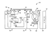
- the vehicle 10 transmits an engine 12 as a power source and a torque that is generated in the engine 12 and forms a gear stage according to the traveling state of the vehicle 10.
- the front differential mechanism 14 for distributing the torque transmitted from the automatic transmission 13 to the left and right front drive shafts 22L, 22R, and the torque transmitted by the propeller shaft 21 to the left and right rear drive shafts 23L, 23R.
- a transfer 16 that distributes the torque transmitted by the automatic transmission 13 to the front wheels 17L, 17R and the rear wheels 18L, 18R.
- the vehicle 10 includes an ECU (Electronic Control Unit) 100 as a vehicle electronic control device for controlling the entire vehicle 10, a hydraulic control device 110 that controls the automatic transmission 13 and the transfer 16 by hydraulic pressure, a driver, And an operation panel 120 serving as an input / output interface.
- ECU Electronic Control Unit
- the vehicle 10 includes a crank sensor 131, an input shaft rotational speed sensor 133, an output gear rotational speed sensor 134, a shift sensor 141, an accelerator sensor 142, and a foot brake sensor (hereinafter referred to as “the brake sensor”). , FB sensor) 143, throttle sensor 145, wheel speed sensor 160, transfer input rotation speed sensor 163, transfer output rotation speed sensor 164, distribution SW sensor 165, and other various sensors (not shown). . Each sensor provided in the vehicle 10 outputs a detected detection signal to the ECU 100.
- a general vehicle does not include all of the sensors 131 to 165, and the present invention does not necessarily include all of the sensors 131 to 165.
- the function can be replaced by another sensor, or the same control can be performed by a value detected by another sensor.
- the vehicle 10 may not include a replaceable sensor.
- the reason why a sensor that is not provided in such a general vehicle is provided is to explain processing when such a sensor is used.
- the engine 12 is configured by a known power device that outputs torque by burning a mixture of hydrocarbon fuel such as gasoline or light oil and air in a combustion chamber of a cylinder (not shown).
- the engine 12 performs automatic transmission by reciprocating the piston in the cylinder by intermittently repeating the intake, combustion, and exhaust of the air-fuel mixture in the combustion chamber, and rotating the crankshaft connected to the piston so that power can be transmitted. Torque is transmitted to the machine 13.
- the fuel used for the engine 12 may be an alcohol fuel containing alcohol such as ethanol.
- the automatic transmission 13 includes a plurality of planetary gear devices, and takes gear stages according to a combination of engagement states and release states of clutches and brakes as a plurality of friction engagement elements provided in these planetary gear devices. It is like that.
- the clutch and brake can be switched between an engaged state and a released state by a hydraulic control device 110.
- the automatic transmission 13 decelerates or increases the rotation of the crankshaft input as the power of the engine 12, that is, the torque at a predetermined gear ratio ⁇ , and outputs it to the front differential mechanism 14 and the transfer 16.
- the stepped transmission is configured to form a shift stage according to the running state and perform speed conversion according to each shift stage. Details of the automatic transmission 13 will be described later.
- the automatic transmission 13 may be a continuously variable transmission that continuously changes the gear ratio.
- the front differential mechanism 14 allows a difference in rotational speed between the front wheel 17L and the front wheel 17R when traveling on a curve or the like.
- the front differential mechanism 14 includes a plurality of gears, and distributes the torque input by the automatic transmission 13 to the front drive shafts 22L and 22R for output.
- the front differential mechanism 14 may be configured such that the front drive shafts 22L and 22R have the same rotation and can take a differential lock state that does not allow a difference in rotational speed between the front wheels 17L and the front wheels 17R. Details of the front differential mechanism 14 will also be described later.
- the rear differential mechanism 15 has substantially the same configuration as the front differential mechanism 14, and therefore description thereof is omitted.
- the transfer 16 is also called an auxiliary transmission, and distributes and transmits the torque transmitted by the automatic transmission 13 to the front differential mechanism 14 and the rear differential mechanism 15, that is, the torque is transmitted to the front wheels 17L and 17R. And can be distributed and transmitted to the rear wheels 18L and 18R.
- the transfer 16 is used during normal travel and four-wheel drive. When traveling, it operates as follows. That is, the transfer 16 does not transmit the torque transmitted by the automatic transmission 13 to the rear differential mechanism 15 but only the front differential mechanism 14 during normal travel. The transfer 16 also transmits the torque transmitted by the automatic transmission 13 to the rear differential mechanism 15 and distributes the torque to the front differential mechanism 14 and the rear differential mechanism 15 during four-wheel drive traveling. It is like that. Details of the transfer 16 will also be described later.
- the ECU 100 includes a CPU (Central Processing Unit) as a central processing unit, a ROM (Read Only Memory) for storing fixed data, a RAM (Random Access Memory) for temporarily storing data, and a rewritable nonvolatile memory.
- a CPU Central Processing Unit
- ROM Read Only Memory
- RAM Random Access Memory
- EEPROM Electrically Erasable and Programmable Read Only Memory
- an input / output interface circuit composed of the above-mentioned memories are provided to control the vehicle 10.
- the ECU 100 is connected to a crank sensor 131, an accelerator sensor 142, and the like.
- the ECU 100 detects the engine speed Ne, the accelerator opening Acc, and the like based on detection signals output from these sensors.
- the ECU 100 controls the hydraulic control device 110 to control the hydraulic pressure of each part of the automatic transmission 13 and the transfer 16. Note that the characteristic functions of the ECU 100 will be described later.
- the ROM of the ECU 100 stores an operation table for realizing each gear stage described later and a program for executing vehicle control. Further, the ROM of the ECU 100 also stores a throttle opening degree control map, a shift diagram, a lockup control map, specification values of the vehicle 10 and the like which are not described in detail.
- the accelerator depression determination value Acc_tv, the deceleration threshold map, the deceleration threshold calculation formula, the output reduction accelerator opening Acn, and the like are stored in the ROM of the ECU 100 as necessary.
- the deceleration threshold value calculation formula includes formulas for calculating a second deceleration threshold value and a third deceleration threshold value, which will be described later, in addition to the formula for calculating the first deceleration threshold value.
- the accelerator depression determination value Acc_tv is a determination value for determining whether to enter the accelerator on state or the accelerator off state according to the depression amount of the accelerator pedal 212.
- the deceleration threshold map is a map for determining the deceleration threshold according to the vehicle speed V and the accelerator opening Acc of the vehicle 10.
- the deceleration threshold value map is a two-dimensional table in which a first deceleration threshold value is set for each predetermined value of the vehicle speed V and the accelerator opening degree Acc.
- the first deceleration threshold value is a determination value of the acceleration ⁇ r that determines whether or not the vehicle 10 is decelerating. As will be described later, the acceleration ⁇ r is calculated by the ECU 100 based on the time change of the wheel speed Vs detected by the wheel speed sensor 160.
- the deceleration threshold value map also stores the second deceleration threshold value and the third deceleration threshold value together with the first deceleration threshold value.
- the second deceleration threshold is a determination value of the acceleration ⁇ r for determining whether or not the deceleration of the vehicle 10 is a deceleration due to a disturbance such as a rough road
- the third deceleration threshold is the vehicle 10. Is a determination value of the acceleration ⁇ r for determining whether or not the acceleration is acceleration due to disturbance such as a rough road.
- an acceleration ⁇ r that is impossible for the vehicle 10 is set according to the specification value of the vehicle 10 or the like.
- the ECU100 determines a 1st deceleration threshold value, a 2nd deceleration threshold value, and a 3rd deceleration threshold value by the detected vehicle speed V and accelerator opening degree Acc based on this deceleration threshold value map. Further, when the detected vehicle speed V and the accelerator opening degree Acc are the vehicle speed V and the accelerator opening degree Acc that are not set in the deceleration threshold map, the ECU 100 is set in the deceleration threshold map.
- the first deceleration threshold value, the second deceleration threshold value, and the third deceleration threshold value are determined by interpolation from other values, for example, by linear conversion.
- the ECU 100 determines that the vehicle 10 is decelerating if the acceleration ⁇ r is less than or equal to the determined first deceleration threshold, and if the acceleration ⁇ r is greater than the determined first deceleration threshold, Judge that there is no. Similarly, the ECU 100 determines that the vehicle 10 is decelerated due to a disturbance if the acceleration ⁇ r is less than or equal to the determined second deceleration threshold, and if the acceleration ⁇ r is greater than the determined second deceleration threshold, the ECU 100 determines that the acceleration ⁇ r is greater than the determined second deceleration threshold. It is determined that deceleration of the vehicle 10 cannot be determined.
- the ECU determines that the acceleration of the vehicle 10 is caused by a disturbance if the acceleration ⁇ r is equal to or greater than the determined third deceleration threshold, and if the acceleration ⁇ r is smaller than the determined third deceleration threshold, the vehicle caused by the disturbance. It is determined that 10 acceleration cannot be determined.
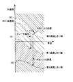
- FIG. 3 shows a graph of the first deceleration threshold, the second deceleration threshold, and the third deceleration threshold set by the deceleration threshold map when the accelerator opening Acc is the maximum.
- the maximum accelerator opening Acc is referred to as WOT (Wide open throttle).
- the deceleration threshold value calculation formula is calculated when the first deceleration threshold value, the second deceleration threshold value, and the third deceleration threshold value are calculated according to the vehicle speed V of the vehicle 10 and the accelerator opening degree Acc. It is a formula.
- a first deceleration threshold value calculation formula for calculating the first deceleration threshold value is a formula representing a one-dot chain line 181 indicating the first deceleration threshold value shown in FIG.
- the second deceleration threshold value calculation formula for calculating the second deceleration threshold value is an equation representing the solid line 182 indicating the second deceleration threshold value shown in FIG. 3, and calculates the third deceleration threshold value.
- the third deceleration threshold value calculation formula is a formula representing a two-dot chain line 183 indicating the third deceleration threshold value shown in FIG.
- the broken line 180 indicates the acceleration ⁇ r at the vehicle speed V when the foot brake pedal 213 is not depressed in the WOT.
- the ECU 100 may store either the deceleration threshold map or the deceleration threshold calculation formula in the ROM.
- the ECU 100 also performs the first deceleration threshold set by the deceleration threshold value calculation formula, the first deceleration threshold value, the second deceleration threshold value, the third deceleration threshold value set by the deceleration threshold value map.
- the threshold value, the second deceleration threshold value, and the third deceleration threshold value are set to be different from each other, or any one of them is set to a different value. Both may be provided and switched according to conditions such as a running state.
- the accelerator opening Acn for lowering the output is an accelerator opening that is set to reduce the output of the engine 12 from the actual accelerator opening Acc when a later-described control permission condition is satisfied. Note that the output reduction accelerator opening Acn may also be calculated according to the traveling state of the vehicle 10.
- the hydraulic control device 110 includes linear solenoid valves SLT and SLU as electromagnetic valves controlled by the ECU 100, on / off solenoid valves SL, and linear solenoid valves SL1 to SL5.
- the hydraulic control device 110 is controlled by the ECU 100 to switch the hydraulic circuit and control the hydraulic pressure by the solenoid valves, and operate each part of the automatic transmission 13. Therefore, the hydraulic control device 110 causes the automatic transmission 13 to configure a desired gear position by switching each solenoid valve.
- the operation panel 120 is connected to the ECU 100 and receives an input operation from the driver, assists the driver, displays the running state of the vehicle, and the like. For example, when the driver inputs a travel mode using a switch or the like provided on the operation panel 120, a signal indicating the input of the travel mode is output to the input / output interface of the ECU 100.
- the crank sensor 131 is controlled by the ECU 100 to detect the rotational speed of the crankshaft 24 and to output a detection signal corresponding to the detected rotational speed to the ECU 100. Further, the ECU 100 acquires the rotation speed of the crankshaft 24 represented by the detection signal output from the crank sensor 131 as the engine rotation speed Ne.
- the input shaft rotational speed sensor 133 is controlled by the ECU 100 to detect the rotational speed of the input shaft 71, which will be described later, and output a detection signal corresponding to the detected rotational speed to the ECU 100.
- the input shaft 71 is directly connected to a turbine shaft 62 of the torque converter 60 described later, and is the same as the rotational speed of the turbine shaft 62. Therefore, hereinafter, the input shaft detected by the input shaft rotational speed sensor 133 is used.
- the rotational speed Nm is set as the turbine rotational speed Nt.
- the output gear rotation speed sensor 134 is controlled by the ECU 100 to detect the rotation speed of an output gear 72 described later and to output a detection signal corresponding to the detected rotation speed to the ECU 100.
- the ECU 100 can also calculate the vehicle speed V based on the rotational speed of the output gear 72 detected by the output gear rotational speed sensor 134. Therefore, the output gear rotation speed sensor 134 detects the driving state of the vehicle 10. That is, the output gear rotation speed sensor 134 constitutes an operation state detection unit.
- the output gear rotation speed sensor 134 detects the vehicle speed V. That is, the output gear rotation speed sensor 134 constitutes a vehicle speed detection means.
- ECU 100 calculates gear ratio ⁇ based on speed change mechanism input speed Nm input from input shaft speed sensor 133 and speed change mechanism output speed Nc input from output gear speed sensor 134. You can also do that. Note that the speed ratio ⁇ is obtained by dividing the actual rotational speed Nm of the input shaft 71 by the actual rotational speed Nc of the output gear 72.
- the shift sensor 141 is controlled by the ECU 100 to detect which of the plurality of switching positions the shift lever 211 is in, and outputs a detection signal indicating the switching position of the shift lever 211 to the ECU 100. It has become.
- the shift lever 211 has a D position corresponding to a drive range (hereinafter simply referred to as a D range), an N position corresponding to a neutral range, an R position corresponding to a reverse range, from the rear to the front of the vehicle 10. P position corresponding to the parking range is taken.
- a D range a drive range
- N position corresponding to a neutral range
- R position corresponding to a reverse range
- the speed stage of the speed change mechanism 70 described later forms one of the first speed to the sixth speed.
- the ECU 100 The shift speed is selected from the shift speeds based on the vehicle speed V and the throttle opening ⁇ th.
- the accelerator sensor 142 is controlled by the ECU 100 to detect an amount of depression (hereinafter referred to as a stroke) by which the accelerator pedal 212 is depressed, and outputs a detection signal corresponding to the detected stroke to the ECU 100. Yes.
- the ECU 100 calculates the accelerator opening Acc from the stroke of the accelerator pedal 212 represented by the detection signal output from the accelerator sensor 142.
- the accelerator sensor 142 detects the driving state of the vehicle 10 including the torque request amount of the torque output from the engine 12. That is, the accelerator sensor 142 constitutes an operation state detection unit. The accelerator sensor 142 detects the depression of the accelerator pedal 212. That is, the accelerator sensor 142 constitutes an accelerator detection means.
- the FB sensor 143 is controlled by the ECU 100 to detect whether or not the foot brake pedal 213 is depressed and outputs a detection signal to the ECU 100.
- the FB sensor 143 detects the driving state of the vehicle 10. That is, the FB sensor 143 constitutes an operation state detection unit.
- the FB sensor 143 detects depression of the foot brake pedal 213. That is, the FB sensor 143 constitutes a brake detection unit.
- the throttle sensor 145 is controlled by the ECU 100 to detect the opening degree of the throttle valve of the engine 12 driven by a throttle actuator (not shown), and to output a detection signal corresponding to the detected opening degree to the ECU 100. It has become.
- the ECU 100 is configured to acquire the throttle valve opening represented by the detection signal output from the throttle sensor 145 as the throttle opening ⁇ th.
- the ECU 100 obtains the throttle opening ⁇ th from the accelerator opening Acc based on the throttle opening control map, the throttle obtained from the throttle opening control map without using the detection signal output from the throttle sensor 145.
- the opening degree ⁇ th can be used as a detection value.
- the ECU 100 obtains the throttle opening ⁇ th from the changed output decreasing accelerator opening Acn.
- the wheel speed sensor 160 is controlled by the ECU 100 to detect the rotational speeds of the front drive shaft 22L, the front drive shaft 22R, the rear drive shaft 23L, and the rear drive shaft 23R, and detection corresponding to the detected rotational speeds. A signal is output to the ECU 100. Further, the ECU 100 determines the rotational speeds of the front drive shaft 22L, the front drive shaft 22R, the rear drive shaft 23L, and the rear drive shaft 23R represented by the detection signals output from the wheel speed sensor 160 as wheel rotational speeds NfL, NfR, NrL, Acquired as NrR.
- the ECU 100 calculates wheel speeds VfL, VfR, VrL, VrR based on the wheel rotational speeds NfL, NfR, NrL, NrR acquired from the wheel speed sensor 160. Further, the ECU 100 calculates the vehicle speed V from the wheel rotation speeds NfL, NfR, NrL, NrR acquired from the wheel speed sensor 160 or the calculated wheel speeds VfL, VfR, VrL, VrR. For example, the ECU 100 obtains the second wheel speed Vs from the slower one from the calculated wheel speeds VfL, VfR, VrL, VrR (hereinafter referred to as Vs), and sets the wheel speed Vs as the vehicle speed V.
- Vs the second wheel speed Vs from the slower one from the calculated wheel speeds VfL, VfR, VrL, VrR
- the wheel speed sensor 160 detects the driving state of the vehicle 10. That is, the wheel speed sensor 160 constitutes a driving state detection unit. Further, the wheel speed sensor 160 detects the wheel speed Vs of the vehicle 10. The wheel speed sensor 160 may detect the wheel speed Vs of all the wheels of the vehicle 10 or may detect the wheel speed Vs of only the driving wheels of the vehicle 10. That is, the wheel speed sensor 160 constitutes wheel speed detection means.
- the transfer input rotational speed sensor 163 is controlled by the ECU 100 to detect the rotational speed TRin of the input shaft of the transfer 16 and output a detection signal corresponding to the detected rotational speed to the ECU 100. Specifically, the ECU 100 detects the rotational speed of the input shaft 54 of the transfer clutch 53 described later.
- the transfer output rotational speed sensor 164 is controlled by the ECU 100 to detect the rotational speed TRout of the output shaft of the transfer 16 and output a detection signal corresponding to the detected rotational speed to the ECU 100. Specifically, the ECU 100 detects the rotation speed of the propeller shaft 21.
- the distribution SW sensor 165 is controlled by the ECU 100 to detect whether the power changeover switch 215 is in the two-wheel drive selection position or the four-wheel drive selection position, and represents the changeover position of the power changeover switch 215. A detection signal is output to the ECU 100.
- selecting the four-wheel drive by the power changeover switch 215 and selecting the transfer gear as the low gear is referred to as selection of L4-SW.
- the power changeover switch 215 selects a distribution ratio between the driving force of the front wheels 17L and 17R and the driving force of the rear wheels 18L and 18R, instead of the two-wheel drive selection and the four-wheel drive selection. It may be possible.
- the automatic transmission 13 includes a torque converter 60 that transmits torque output from the engine 12, a rotation speed of an input shaft 71 that is an input shaft, and a rotation speed of an output gear 72 that is an output gear. And a speed change mechanism 70 that performs the speed change.
- a reduction gear mechanism is provided between the speed change mechanism 70 and the front differential mechanism 14 so as to input torque from the speed change mechanism 70 and increase the driving force while decreasing the rotational speed to output to the front differential mechanism 14.
- torque is directly transmitted from the speed change mechanism 70 to the front differential mechanism 14 without providing a reduction gear mechanism in order to simplify the description.
- the torque converter 60 is disposed between the engine 12 and the transmission mechanism 70, and changes the direction of the oil flow, the pump impeller 63 that inputs torque from the engine 12, the turbine runner 64 that outputs torque to the transmission mechanism 70, and the oil flow.
- a stator 66 and a lock-up clutch 67 that directly connects the pump impeller 63 and the turbine runner 64 are provided to transmit torque via oil.
- the pump impeller 63 is connected to the crankshaft 24 of the engine 12. Further, the pump impeller 63 is rotated integrally with the crankshaft 24 by the torque of the engine 12.
- the turbine runner 64 is connected to the turbine shaft 62, and the turbine shaft 62 is connected to the speed change mechanism 70.
- the turbine shaft 62 is directly connected to an input shaft 71 that is an input shaft of the speed change mechanism 70.
- the turbine runner 64 is rotated by the flow of oil pushed out by the rotation of the pump impeller 63, and outputs the rotation of the crankshaft 24 of the engine 12 to the speed change mechanism 70 via the turbine shaft 62. .
- the stator 66 is rotatably supported by the housing 31 of the automatic transmission 13 serving as a non-rotating member via a one-way clutch 65.
- the stator 66 flows out of the turbine runner 64 and again changes the direction of the oil flowing into the pump impeller 63 to change the force to further rotate the pump impeller 63.
- the stator 66 is prevented from rotating by the one-way clutch 65, and changes the direction in which this oil flows.
- stator 66 rotates idly and prevents reverse torque from acting on the turbine runner 64.
- the lock-up clutch 67 directly connects the pump impeller 63 and the turbine runner 64, and mechanically directly transmits the rotation of the crankshaft 24 of the engine 12 to the turbine shaft 62.
- the torque converter 60 transmits rotation between the pump impeller 63 and the turbine runner 64 via oil. Therefore, the rotation of the pump impeller 63 cannot be transmitted 100% to the turbine runner 64. Therefore, when the rotational speed of the crankshaft 24 and the turbine shaft 62 approaches, the lockup clutch 67 is operated to mechanically directly connect the pump impeller 63 and the turbine runner 64. More specifically, the crankshaft 24 And the turbine shaft 62 are mechanically connected directly to increase the transmission efficiency of the rotation from the engine 12 to the speed change mechanism 70 and improve the fuel efficiency.
- the lock-up clutch 67 can realize a flex lock-up that slides at a predetermined slip rate.
- the state of the lock-up clutch 67 is determined based on the travel state of the vehicle 10 based on the lock-up control map stored in the ROM of the ECU 100, specifically, the CPU of the ECU 100 according to the vehicle speed V and the accelerator opening Acc. To be selected.
- the state of the lock-up clutch 67 includes a converter state in which the lock-up clutch 67 is released, a lock-up state in which the lock-up clutch 67 is fastened, and a flex lock-up state in which the lock-up clutch 67 is slid. , One of the states.
- the pump impeller 63 is provided with a mechanical oil pump 68 that generates hydraulic pressure for shifting the speed change mechanism 70 and hydraulic pressure for supplying oil for operation, lubrication and cooling to each part. ing.
- the transmission mechanism 70 includes an input shaft 71, an output gear 72, a first planetary gear device 73, a second planetary gear device 74, a C1 clutch 75, a C2 clutch 76, a B1 brake 77, a B2 brake 78, and a B3.
- a brake 79 and an F one-way clutch 80 are provided.
- the input shaft 71 is directly connected to the turbine shaft 62 of the torque converter 60. Therefore, the input shaft 71 directly inputs the output rotation of the torque converter 60.
- the output gear 72 is connected to the carrier of the second planetary gear unit 74 and engages with a differential ring gear 42 described later of the front differential mechanism 14 to function as a counter drive gear. Therefore, the output gear 72 transmits the output rotation of the speed change mechanism 70 to the front differential mechanism 14.
- the first planetary gear unit 73 is composed of a single pinion type planetary gear mechanism.
- the first planetary gear device 73 includes a sun gear S1, a ring gear R1, a pinion gear P1, and a carrier CA1.
- the sun gear S1 is connected to the input shaft 71. Therefore, the sun gear S ⁇ b> 1 is connected to the turbine shaft 62 of the torque converter 60 via the input shaft 71.
- the ring gear R1 is selectively fixed to the housing 31 of the automatic transmission 13 via the B3 brake 79.
- the pinion gear P1 is rotatably supported by the carrier CA1.
- the pinion gear P1 is engaged with the sun gear S1 and the ring gear R1.
- the carrier CA1 is selectively fixed to the housing 31 via the B1 brake 77.
- the second planetary gear unit 74 is constituted by a Ravigneaux type planetary gear mechanism.
- the second planetary gear unit 74 includes a sun gear S2, ring gears R2 and R3, a short pinion gear P2, a long pinion gear P3, a sun gear S3, a carrier CA2, and a carrier CA3.
- the sun gear S2 is connected to the carrier CA1 of the first planetary gear device 73.
- the ring gears R2 and R3 are selectively connected to the input shaft 71 via the C2 clutch 76.
- the ring gears R2 and R3 are selectively fixed to the housing 31 via a B2 brake 78. Also, the ring gears R2 and R3 are prevented from rotating in the direction opposite to the rotation direction of the input shaft 71 (hereinafter referred to as the reverse direction) by the F one-way clutch 80 provided in parallel with the B2 brake 78. Yes.
- the short pinion gear P2 is rotatably supported by the carrier CA2.
- Short pinion gear P2 is engaged with sun gear S2 and long pinion gear P3.
- the long pinion gear P3 is rotatably supported by the carrier CA3.
- the long pinion gear P3 is engaged with the short pinion gear P2, the sun gear S3, and the ring gears R2 and R3.
- the sun gear S3 is selectively connected to the input shaft 71 via the C1 clutch 75.
- the carrier CA2 is connected to the output gear 72.
- the carrier CA3 is connected to the carrier CA2 and the output gear 72.
- the B1 brake 77, the B2 brake 78, and the B3 brake 79 are fixed to the housing 31 of the automatic transmission 13.
- the C1 clutch 75, the C2 clutch 76, the F one-way clutch 80, the B1 brake 77, the B2 brake 78, and the B3 brake 79 (hereinafter simply referred to as the clutch C and the brake B unless otherwise specified) are multi-plate clutches and brakes.
- the hydraulic friction engagement device is controlled to be engaged by a hydraulic actuator.
- the clutch C and the brake B correspond to a hydraulic circuit that is switched according to excitation or de-energization of the linear solenoid valves SL1 to SL5, SLU, SLT, and the on / off solenoid valve SL of the hydraulic control device 110 and an operating state of a manual valve (not shown).
- the state can be switched between the engaged state and the released state.
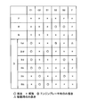
- the operation table that realizes each shift speed is a state in which each friction engagement element of the speed change mechanism 70, that is, the engagement and release states of the clutch C and the brake B, in order to realize each shift speed. Is shown.
- “ ⁇ ” represents engagement.
- “X” represents release.
- “ ⁇ ” represents engagement only during engine braking.
- “ ⁇ ” represents engagement only during driving.
- each friction engagement element is operated by excitation, de-excitation, or current control of linear solenoid valves SL1 to SL5 provided in the hydraulic control device 110 (see FIG. 1) and a transmission solenoid (not shown).
- a forward shift stage of 1st to 6th speed and a reverse shift stage are formed.
- the ECU 100 when realizing the first speed, engages the F one-way clutch 80 in addition to the engagement of the C1 clutch 75 during driving. In addition, when realizing the first speed, the ECU 100 engages the B2 brake 78 in addition to the engagement of the C1 clutch 75 when applying the engine brake.
- the ECU 100 engages the B2 brake 78 and the B3 brake 79 when realizing the reverse gear. Further, the ECU 100 releases all of the C1 clutch 75, the C2 clutch 76, the B1 brake 77, the B2 brake 78, the B3 brake 79, and the F one-way clutch 80 when realizing the neutral range and the parking range. As described above, the transmission mechanism 70 is in a neutral state in which torque transmission is not performed between the input and output of the transmission mechanism 70 by releasing all the friction engagement elements.
- the linear solenoid valve SLT controls the hydraulic pressure of the line pressure PL that is the original pressure of the oil supplied to each part.
- the linear solenoid valve SLT includes a throttle opening ⁇ th, an intake air amount Qar of the engine 12, a cooling water temperature Tw of the engine 12, an engine speed Ne, an input shaft speed Nm, that is, a turbine speed Nt, automatic Based on the oil temperature Tf, shift position Psh, shift range, etc. of the transmission 13 and the hydraulic control device 110, the ECU 100 controls the line pressure PL.
- the linear solenoid valve SLU performs lock-up control in the torque converter 60.
- the linear solenoid valve SLU includes an engine speed Ne that is an input speed of the torque converter 60, a turbine speed Nt that is an output speed of the torque converter 60, a throttle opening ⁇ th, a vehicle speed V, an input torque, and the like. Is controlled by the ECU 100 to adjust the pressure of a lockup relay valve and a lockup control valve (not shown) to control the lockup clutch 67.
- the on / off solenoid valve SL switches the hydraulic pressure of the lockup relay valve.
- the linear solenoid valves SL1 to SL5 are designed to perform shift control.
- Linear solenoid valves SL1 and SL2 control the hydraulic pressures of the C1 clutch 75 and the C2 clutch 76.
- the linear solenoid valves SL3, SL4, and SL5 control the hydraulic pressures of the B1 brake 77, the B2 brake 78, and the B3 brake 79.
- the front differential mechanism 14 includes a hollow differential case 41, a differential ring gear 42 provided on the outer periphery of the differential case 41, a pinion shaft 43 provided inside the differential case 41, and differential pinion gears 44a and 44b. And side gears 45L and 45R.
- the differential pinion gears 44a and 44b and the side gears 45L and 45R are bevel gears.
- the differential case 41 is rotatably held around the front drive shafts 22L and 22R.
- the differential ring gear 42 is provided on the outer periphery of the differential case 41 and is engaged with the output gear 72 of the automatic transmission 13.
- the pinion shaft 43 is fixed so as to rotate integrally with the differential case 41 in parallel with the differential ring gear 42.
- the differential pinion gears 44 a and 44 b are provided to be rotatable around the pinion shaft 43.
- the side gear 45L is provided so as to rotate integrally with the front drive shaft 22L and is engaged with the differential pinion gear 44a and the differential pinion gear 44b.
- the side gear 45R is provided so as to rotate integrally with the front drive shaft 22R, and is engaged with the differential pinion gear 44a and the differential pinion gear 44b.
- the front differential mechanism 14 when the differential pinion gears 44a and 44b do not rotate, the side gear 45L and the side gear 45R rotate equally.
- the front differential mechanism 14 when the differential pinion gears 44a and 44b are rotated, the side gear 45L and the side gear 45R are relatively reversely rotated. Therefore, the front differential mechanism 14 allows a difference in rotational speed between the side gear 45L that rotates integrally with the front drive shaft 22L and the side gear 45R that rotates together with the front drive shaft 22R, and changes a curve or the like. When traveling, the difference in rotational speed between the front wheel 17L and the front wheel 17R can be absorbed.
- the rear differential mechanism 15 has the same configuration as the front differential mechanism 14, and therefore the description thereof is omitted.
- the differential ring gear 42 is engaged with the pinion gear of the propeller shaft 21 instead of the output gear 72 of the automatic transmission 13.
- the left and right side gears of the rear differential mechanism 15 are provided to rotate integrally with the rear drive shafts 23L and 23R instead of the front drive shafts 22L and 22R.
- the transfer 16 includes a hypoid gear 51, a hypoid pinion 52, and a transfer clutch 53.
- the hypoid gear 51 rotates integrally with the differential case 41 of the front differential mechanism 14 and inputs torque from the automatic transmission 13 to the transfer 16 via the front differential mechanism 14.
- the hypoid pinion 52 is, for example, a bevel gear together with the hypoid gear 51, and converts the rotational direction of torque input from the hypoid gear 51 by 90 °.
- the transfer clutch 53 includes an input shaft 54, a multi-plate clutch disk 55, a multi-plate clutch plate 56, and a piston 57, and a hydraulic servo chamber 58 is formed therein.
- the transfer clutch 53 connects the hypoid pinion 52 and the propeller shaft 21 side so as to be able to transmit torque.
- the transfer clutch 53 itself is a known hydraulic servo type wet multi-plate clutch.
- the input shaft 54 is connected to the hypoid pinion 52 so that torque is input from the hypoid pinion 52 and transmitted to the multi-plate clutch disk 55.
- the multi-plate clutch plate 56 transmits torque to the propeller shaft 21.
- the multi-plate clutch disk 55 and the multi-plate clutch plate 56 form a multi-plate clutch.
- the hydraulic pressure in the hydraulic servo chamber 58 is controlled by a hydraulic control device, and when the hydraulic pressure is supplied into the hydraulic servo chamber 58, the piston 57 presses the multi-plate clutch disc 55 and the multi-plate clutch plate 56 with a predetermined pressure. A predetermined torque transmission amount is ensured by this pressing force.
- the transfer 16 distributes the driving force of the engine 12 to the front wheels 17L, 17R and the rear wheels 18L, 18R. That is, the transfer 16 constitutes a power distribution device.
- the ECU 100 executes a reduction control for reducing the torque output from the engine 12 with respect to the torque request amount. Further, the ECU 100 detects the depression of the accelerator pedal 212 by the accelerator sensor 142, detects the depression of the foot brake pedal 213 by the FB sensor 143, and calculates the acceleration ⁇ r calculated by the change in the wheel speed Vs detected by the wheel speed sensor 160. Is equal to or less than the set first deceleration threshold value and the acceleration ⁇ r is within a predetermined range, the lowering control is executed, and the accelerator sensor 142 does not detect depression of the accelerator pedal 212 or the FB sensor. When the depression of the foot brake pedal 213 is not detected by 143, the acceleration ⁇ r is not less than or equal to the set first deceleration threshold value, or the acceleration ⁇ r is out of the predetermined range, the decrease control is not executed. ing.
- the ECU 100 determines that the acceleration ⁇ r is out of the predetermined range and does not execute the decrease control for a predetermined time.
- the ECU 100 is configured to set a predetermined range according to the vehicle speed V detected by the output gear rotation speed sensor 134. Further, the ECU 100 sets a predetermined range according to the depression amount of the accelerator pedal 212 detected by the accelerator sensor 142. That is, the ECU 100 constitutes output control means.
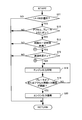
- FIG. 7 represents the execution contents of a vehicle control process program executed by the CPU of the ECU 100 using the RAM as a work area.
- This vehicle control processing program is stored in the ROM of the ECU 100.
- the vehicle control process is executed by the CPU of the ECU 100 at predetermined time intervals.
- the ECU 100 determines whether or not L4-SW is not selected (step S11).
- ECU 100 determines whether both the accelerator and the brake are on, and if the accelerator or the brake is not on, The vehicle control process ends (step S12). Specifically, ECU 100 determines whether or not accelerator opening Acc detected by accelerator sensor 142 is greater than or equal to accelerator depression determination value Acc_tv stored in ROM, and accelerator opening Acc is determined as accelerator depression determination value. If it is greater than or equal to Acc_tv, the accelerator pedal 212 is depressed, that is, it is determined that the accelerator is on, and if the accelerator opening Acc is less than the accelerator depression determination value Acc_tv, the accelerator pedal 212 is not depressed.
- the ECU 100 detects that the foot brake pedal 213 is depressed, that is, the brake is on, or the foot brake pedal 213 is not depressed, that is, the brake is off, based on the detection signal detected by the FB sensor 143. Determine if there is.
- the ECU 100 starts a timer when the accelerator is on and the brake is on (determined as YES in step S12) during the both-step determination process (step S12).
- the duration time is monitored, and when the accelerator is turned off or the brake is turned off (determined as NO in step S12), the duration time of the two-step state is cleared and the monitoring is terminated.
- ECU 100 determines whether or not the both-stepping state is less than a certain time, that is, the both-stepping state is not less than the certain time. If the stepping state is longer than a predetermined time, the vehicle control process is terminated (step S13).
- ECU 100 determines that the stepping state is less than the predetermined time (determined as YES in step S13)
- ECU 100 performs a deceleration determination, and if the deceleration determination is not on, that is, if the deceleration determination is off, The vehicle control process is terminated (step S15). A specific description of this deceleration determination process will be described later.
- the ECU100 performs an engine output suppression process, when the deceleration determination is ON (it determines with YES at step S15) (step S18). For example, the ECU 100 rewrites the accelerator opening value to the actual accelerator opening Acc by rewriting the accelerator opening Acn for output reduction for reducing the torque of the engine 12 stored in the ROM from the actual accelerator opening Acc. The torque is lower than the engine output due to.
- the engine torque decreasing speed that is, the ratio of change from the actual accelerator opening Acc to the output decreasing accelerator opening Acn is set to a ratio according to the vehicle speed V, and thus the desired engine torque is decreased.
- the time up to can be set to an equivalent time.
- the ECU 100 determines whether or not an end condition for the engine output suppression process is satisfied (step S19). Specifically, ECU 100 determines whether or not the brake is off, or whether or not the state where the accelerator opening hysteresis width exceeds the predetermined hysteresis width has continued for a predetermined time, and the brake is on, and When the accelerator opening hysteresis width is equal to or smaller than the predetermined hysteresis width or exceeds the predetermined hysteresis width, if the predetermined time has not elapsed, the process returns to the engine output suppression process (step S18).
- the accelerator opening hiss width is a difference between the actual accelerator opening Acc before the engine output suppression process (step S18) and the current actual accelerator opening Acc detected by the accelerator sensor 142. Show.
- step S19 a determination is made as YES, a torque return process of the engine 12 is performed, and the vehicle control process is terminated (step S20).
- the ECU 100 returns the accelerator opening to the actual accelerator opening Acc detected by the accelerator sensor 142, and The torque is restored to the normal driving torque.
- the ECU 100 stores a deceleration threshold map in which the first deceleration threshold is set in accordance with the accelerator opening Acc and the vehicle speed V in the ROM. Further, the second deceleration threshold value and the third deceleration threshold value are also set in this deceleration threshold value map.
- the ECU 100 determines whether or not an acceleration timer, which will be described later, is being set in the deceleration determination process (step S21). If the acceleration timer is being set (determined as YES in step S21), ECU 100 determines whether or not a predetermined time has elapsed from the setting of the acceleration timer. If the predetermined time has not elapsed, ECU 100 The process ends (step S22). The ECU 100 cancels the setting of the acceleration timer if a predetermined time has elapsed since the setting of the acceleration timer (step S23).
- the ECU 100 calculates the acceleration if a predetermined time has elapsed from the setting of the acceleration timer and the acceleration timer setting is canceled (step S23), or if the acceleration timer is not being set (determined as NO in step S21). (Step S24). Specifically, as described above, the ECU 100 detects the wheel speed Vs from the detection value of the wheel speed sensor 160, and calculates the acceleration ⁇ r from the time change of the wheel speed Vs.
- the ECU 100 determines the first deceleration threshold value, the second deceleration threshold value, and the third deceleration threshold value in accordance with the accelerator opening degree Acc and the detected value of the vehicle speed V (step S25). For example, when the accelerator opening is WOT, ECU 100 determines the first deceleration threshold, the second deceleration threshold, and the third deceleration threshold at vehicle speed V based on the deceleration threshold map shown in FIG. And the detected values are determined as the first deceleration threshold value, the second deceleration threshold value, and the third deceleration threshold value.
- the ECU 100 determines whether or not the calculated acceleration ⁇ r is equal to or less than the determined first deceleration threshold value (step S26). If the acceleration ⁇ r is not less than or equal to the first deceleration threshold, that is, if the acceleration ⁇ r is greater than the first deceleration threshold (determined as NO in step S26), the ECU 100 determines that the acceleration ⁇ r is the third deceleration threshold determined above. It is determined whether or not the value is greater than or equal to the value, and if the acceleration ⁇ r is not greater than or equal to the third deceleration threshold value, the vehicle control process is terminated (step S27).
- the ECU 100 sets an acceleration timer and ends the vehicle control process (step S28).
- the acceleration timer means that if there is an acceleration that is not possible as the vehicle 10 due to some disturbance, there is a high possibility that a large deceleration will occur immediately thereafter. It is set to invalidate the deceleration determination for a predetermined time so that it is not determined that the vehicle is decelerating due to. During the acceleration timer setting, the deceleration determination is invalidated, so that unnecessary deceleration determination can be eliminated.
- step S26 ECU 100 determines whether acceleration ⁇ r is equal to or less than the first deceleration threshold value. If the acceleration ⁇ r is equal to or less than the second deceleration threshold value, the vehicle control process is terminated (step S29). If ECU 100 determines that acceleration ⁇ r is not equal to or smaller than the second deceleration threshold value (determined as NO in step S29), ECU 100 determines that deceleration determination is on, ends the deceleration determination process, and proceeds to step S18. Transition.
- the vehicle control apparatus determines acceleration / deceleration due to disturbance when the acceleration ⁇ r calculated by the change in the wheel speed Vs detected by the wheel speed sensor 160 is outside the predetermined range. Because it is determined that the control permission condition is not satisfied, even if the road is traveling on a rough road surface or a slippery road surface, the driving force lowering control is prohibited, and the influence of wheel speed change due to disturbance is eliminated, Deceleration of the vehicle 10 can be appropriately determined, and the driver's intention is reflected to switch the execution of the decrease control, thereby preventing the drivability from deteriorating.
- the vehicle control device determines that the vehicle is decelerated due to disturbance and determines that the control permission condition is not satisfied.
- the vehicle control device determines that the vehicle is decelerated due to disturbance and determines that the control permission condition is not satisfied.
- the vehicle control apparatus in the present embodiment determines that the acceleration is due to disturbance and determines that the control permission condition is not satisfied for a predetermined time.
- the vehicle control apparatus in the present embodiment determines that the acceleration is due to disturbance and determines that the control permission condition is not satisfied for a predetermined time.
- the drive wheels are driven on a rough road surface or the like by detecting the wheel speeds VfL, VfR, VrL, VrR of all the wheels 17L, 17R, 18L, 18R of the vehicle 10. Not only the rolling wheels, but also the accuracy of the determination of whether or not the lowering control is performed can be improved, and the drivability can be prevented from deteriorating.
- the road surface friction coefficient is small while limiting the number of detected parts of the wheel speed Vs.
- the vehicle control apparatus sets a predetermined range for determining acceleration / deceleration due to disturbance according to the vehicle speed V, the range for determining acceleration / deceleration due to disturbance according to the vehicle speed V changes to an appropriate value. Therefore, the acceleration / deceleration determination can be performed more accurately than the determination based on the fixed range, and the accuracy of the determination of whether or not the lowering control is executed can be improved and the deterioration of drivability can be prevented. it can.
- the vehicle control apparatus since the vehicle control apparatus according to the present embodiment sets a predetermined range for determining acceleration / deceleration due to disturbance according to the amount of depression of accelerator pedal 212, it is determined that acceleration / deceleration due to disturbance depends on the amount of depression of accelerator pedal 212. Since the width to be changed can be changed to an appropriate value, the acceleration / deceleration determination can be performed more accurately than the determination based on the fixed range. It is possible to prevent deterioration of the performance.
- the present invention is not limited to this, and an electric vehicle that uses a motor as a power source and hydrogen as fuel. It is also possible to use a hydrogen vehicle using an engine as a power source or a hybrid vehicle using both an engine and a motor.
- the power source for reducing the torque is not limited to the engine 12, but the driving force of a motor or the like may be reduced.
- the present invention is not limited to this, and a plurality of ECUs may be used.
- the ECU 100 of the present embodiment may be configured by a plurality of ECUs such as an E-ECU that performs combustion control of the engine 12 and a T-ECU that performs shift control of the automatic transmission 13. .
- each ECU inputs and outputs necessary information mutually.
- the vehicle control apparatus eliminates the influence of wheel speed change due to disturbance, appropriately determines deceleration of the vehicle 10, and executes the decrease control reflecting the driver's intention.
- the presence / absence can be switched and the deterioration of drivability can be prevented, which is useful as a vehicle control device or the like that performs suppression control of the output of the power source.
Landscapes
- Engineering & Computer Science (AREA)
- Mechanical Engineering (AREA)
- Chemical & Material Sciences (AREA)
- Combustion & Propulsion (AREA)
- General Engineering & Computer Science (AREA)
- Automation & Control Theory (AREA)
- Transportation (AREA)
- Control Of Vehicle Engines Or Engines For Specific Uses (AREA)
- Control Of Transmission Device (AREA)
- Control Of Driving Devices And Active Controlling Of Vehicle (AREA)
- Electrical Control Of Air Or Fuel Supplied To Internal-Combustion Engine (AREA)
- Combined Controls Of Internal Combustion Engines (AREA)
Abstract
Description
まず、本発明の実施の形態における制御装置を備えた車両の構成について、図1に示す車両の概略ブロック構成図、および、図2に示す車両制御の概略ブロック構成図を参照して、説明する。
同様に、ECU100は、加速度αrが決定した第2減速しきい値以下であれば、外乱による車両10の減速と判定し、加速度αrが決定した第2減速しきい値よりも大きければ、外乱による車両10の減速とは断定できないと判定する。また、ECUは、加速度αrが決定した第3減速しきい値以上であれば、外乱による車両10の加速と判定し、加速度αrが決定した第3減速しきい値よりも小さければ、外乱による車両10の加速とは断定できないと判定する。
ここで、ECU100は、アウトプットギヤ回転数センサ134が検出したアウトプットギヤ72の回転数に基づいて、車速Vを算出することも可能となっている。したがって、アウトプットギヤ回転数センサ134は、車両10の運転状態を検出するようになっている。すなわち、アウトプットギヤ回転数センサ134は、運転状態検出手段を構成している。また、アウトプットギヤ回転数センサ134は、車速Vを検出するようになっている。すなわち、アウトプットギヤ回転数センサ134は、車速検出手段を構成している。
アウトプットギヤ72は、第2遊星歯車装置74のキャリアに連結されるとともに、フロントディファレンシャル機構14の後述するディファレンシャルリングギヤ42と係合し、カウンタドライブギヤとして機能する。したがって、アウトプットギヤ72は、変速機構70の出力回転をフロントディファレンシャル機構14に伝達するようになっている。
さらに、ECU100は、中立レンジおよび駐車レンジを実現する場合には、C1クラッチ75、C2クラッチ76、B1ブレーキ77、B2ブレーキ78、B3ブレーキ79およびFワンウェイクラッチ80の全てを解放させる。このように、変速機構70は、全ての摩擦係合要素を解放させることにより、変速機構70の入出力間でトルク伝達が行われないニュートラル状態となる。
リニアソレノイドバルブSLTは、各部に供給するオイルの元圧となるライン圧PLの油圧制御を行うようになっている。具体的には、リニアソレノイドバルブSLTは、スロットル開度θth、エンジン12の吸入空気量Qar、エンジン12の冷却水温Tw、エンジン回転数Ne、インプットシャフト回転数Nm、すなわち、タービン回転数Nt、自動変速機13および油圧制御装置110の油温Tf、シフトポジションPsh、シフトレンジ等に基づいて、ECU100によって制御され、ライン圧PLを調圧するようになっている。
オンオフソレノイドバルブSLは、ロックアップリレーバルブの油圧の切り替えを行うようになっている。
12 エンジン(動力源)
13 自動変速機
14 フロントディファレンシャル機構
15 リヤディファレンシャル機構
16 トランスファ
17L、17R 前輪
18L、18R 後輪
21 プロペラシャフト
22L、22R フロントドライブシャフト
23L、23R リヤドライブシャフト
41 デフケース
53 トランスファクラッチ
100 ECU(出力制御手段)
110 油圧制御装置
120 操作パネル
131 クランクセンサ
133 インプットシャフト回転数センサ
134 アウトプットギヤ回転数センサ(運転状態検出手段、車速検出手段)
142 アクセルセンサ(運転状態検出手段、アクセル検出手段)
143 FBセンサ(運転状態検出手段、ブレーキ検出手段)
145 スロットルセンサ
160 車輪速センサ(運転状態検出手段、車輪速検出手段)
163 トランスファ入力回転数センサ
164 トランスファ出力回転数センサ
165 分配SWセンサ
212 アクセルペダル
213 フットブレーキペダル
215 動力切り替えスイッチ
Claims (7)
- 動力源とアクセルペダルとブレーキペダルとを備えた車両の制御装置において、
前記動力源から出力される駆動力の駆動力要求量を含む前記車両の運転状態を検出する運転状態検出手段と、
前記動力源から出力される駆動力を前記駆動力要求量に対して低下させる低下制御を実行する出力制御手段と、を備え、
前記運転状態検出手段は、前記アクセルペダルの踏み込みを検出するアクセル検出手段と、前記ブレーキペダルの踏み込みを検出するブレーキ検出手段と、前記車両の車輪速を検出する車輪速検出手段と、を有し、
前記出力制御手段は、前記アクセル検出手段によりアクセルペダルの踏み込みが検出され、前記ブレーキ検出手段によりブレーキペダルの踏み込みが検出され、前記車輪速検出手段により検出された車輪速の変化により算出した加速度が設定した第1減速しきい値以下であり、かつ、前記加速度が所定の範囲内であるときは、前記低下制御を実行するとともに、前記アクセル検出手段によりアクセルペダルの踏み込みが検出されないか、前記ブレーキ検出手段によりブレーキペダルの踏み込みが検出されないか、前記加速度が設定した第1減速しきい値以下でないか、または、前記加速度が所定の範囲外であるときは、前記低下制御を実行しないことを特徴とする車両の制御装置。 - 前記出力制御手段は、前記加速度が設定した第2減速しきい値以下であるとき、前記加速度が所定の範囲外であるとして前記低下制御を実行しないことを特徴とする請求項1に記載の車両の制御装置。
- 前記出力制御手段は、前記加速度が設定した第3減速しきい値以上であるとき、前記加速度が所定の範囲外であるとして、所定の時間、前記低下制御を実行しないことを特徴とする請求項1または請求項2に記載の車両の制御装置。
- 前記車輪速検出手段は、前記車両の全ての車輪の車輪速を検出することを特徴とする請求項1から請求項3のいずれか1の請求項に記載の車両の制御装置。
- 前記車輪速検出手段は、前記車両の駆動輪のみの車輪速を検出することを特徴とする請求項1から請求項3のいずれか1の請求項に記載の車両の制御装置。
- 前記運転状態検出手段は、車速を検出する車速検出手段を有し、
前記出力制御手段は、前記車速検出手段に検出された車速に応じて前記所定の範囲を設定することを特徴とする請求項1から請求項5のいずれか1の請求項に記載の車両の制御装置。 - 前記アクセル検出手段は、前記アクセルペダルの踏み込み量を検出し、
前記出力制御手段は、前記アクセル検出手段に検出された前記アクセルペダルの踏み込み量に応じて前記所定の範囲を設定することを特徴とする請求項1から請求項6のいずれか1の請求項に記載の車両の制御装置。
Priority Applications (3)
| Application Number | Priority Date | Filing Date | Title |
|---|---|---|---|
| JP2012509183A JP5299562B2 (ja) | 2010-04-07 | 2010-04-07 | 車両の制御装置 |
| PCT/JP2010/002535 WO2011125123A1 (ja) | 2010-04-07 | 2010-04-07 | 車両の制御装置 |
| US13/639,414 US20130030674A1 (en) | 2010-04-07 | 2010-04-07 | Vehicle control apparatus |
Applications Claiming Priority (1)
| Application Number | Priority Date | Filing Date | Title |
|---|---|---|---|
| PCT/JP2010/002535 WO2011125123A1 (ja) | 2010-04-07 | 2010-04-07 | 車両の制御装置 |
Publications (1)
| Publication Number | Publication Date |
|---|---|
| WO2011125123A1 true WO2011125123A1 (ja) | 2011-10-13 |
Family
ID=44762115
Family Applications (1)
| Application Number | Title | Priority Date | Filing Date |
|---|---|---|---|
| PCT/JP2010/002535 Ceased WO2011125123A1 (ja) | 2010-04-07 | 2010-04-07 | 車両の制御装置 |
Country Status (3)
| Country | Link |
|---|---|
| US (1) | US20130030674A1 (ja) |
| JP (1) | JP5299562B2 (ja) |
| WO (1) | WO2011125123A1 (ja) |
Families Citing this family (11)
| Publication number | Priority date | Publication date | Assignee | Title |
|---|---|---|---|---|
| JP5019002B2 (ja) | 2009-12-17 | 2012-09-05 | トヨタ自動車株式会社 | 車両の制御装置 |
| WO2011074036A1 (ja) | 2009-12-17 | 2011-06-23 | トヨタ自動車株式会社 | 車両の制御装置 |
| US20130030675A1 (en) * | 2010-04-07 | 2013-01-31 | Toyota Jidosha Kabushiki Kaisha | Vehicle control apparatus |
| WO2012108028A1 (ja) * | 2011-02-10 | 2012-08-16 | トヨタ自動車株式会社 | ハイブリッド車両およびハイブリッド車両の制御方法 |
| US20170028234A1 (en) * | 2015-07-31 | 2017-02-02 | Delta Electronics, Inc. | Ventilation fan |
| US10233855B2 (en) * | 2016-04-15 | 2019-03-19 | Toyota Jidosha Kabushiki Kaisha | Failure diagnosis apparatus for diagnosing an insufficient output of an internal combustion engine |
| JP6521491B1 (ja) * | 2017-12-01 | 2019-05-29 | マツダ株式会社 | 車両の制御装置 |
| JP2019206206A (ja) * | 2018-05-28 | 2019-12-05 | トヨタ自動車株式会社 | 駆動力制御装置 |
| CN114326710B (zh) * | 2021-12-04 | 2024-05-24 | 深圳市普渡科技有限公司 | 机器人、机器人行驶策略确定方法、装置和存储介质 |
| KR20230138819A (ko) * | 2022-03-24 | 2023-10-05 | 현대모비스 주식회사 | 도로의 돌출부 통과에 따른 차량의 제어 방법 및 장치 |
| US12221105B2 (en) * | 2022-08-22 | 2025-02-11 | Arvinmeritor Technology, Llc | System and method of controlling torque provided with an axle assembly |
Citations (4)
| Publication number | Priority date | Publication date | Assignee | Title |
|---|---|---|---|---|
| JPH05238290A (ja) * | 1992-02-28 | 1993-09-17 | Mazda Motor Corp | 車両の自動制動装置 |
| JPH0719077A (ja) * | 1993-06-30 | 1995-01-20 | Fujitsu Ten Ltd | スロットル制御方法 |
| JP2005207260A (ja) * | 2004-01-21 | 2005-08-04 | Nissan Motor Co Ltd | スロットル制御装置 |
| JP2005291030A (ja) * | 2004-03-31 | 2005-10-20 | Isuzu Motors Ltd | 車両安全装置 |
Family Cites Families (5)
| Publication number | Priority date | Publication date | Assignee | Title |
|---|---|---|---|---|
| JP3608052B2 (ja) * | 2001-08-09 | 2005-01-05 | トヨタ自動車株式会社 | 乗員保護装置の起動制御装置 |
| JP4639997B2 (ja) * | 2005-02-18 | 2011-02-23 | トヨタ自動車株式会社 | 車両の減速制御装置 |
| JP2011025720A (ja) * | 2009-07-21 | 2011-02-10 | Denso Corp | 加速度制御装置 |
| US20120259524A1 (en) * | 2009-12-28 | 2012-10-11 | Toyota Jidosha Kabushiki Kaisha | Vehicle control apparatus |
| EP2557302B1 (en) * | 2010-04-07 | 2016-09-07 | Toyota Jidosha Kabushiki Kaisha | Vehicle control device |
-
2010
- 2010-04-07 WO PCT/JP2010/002535 patent/WO2011125123A1/ja not_active Ceased
- 2010-04-07 US US13/639,414 patent/US20130030674A1/en not_active Abandoned
- 2010-04-07 JP JP2012509183A patent/JP5299562B2/ja active Active
Patent Citations (4)
| Publication number | Priority date | Publication date | Assignee | Title |
|---|---|---|---|---|
| JPH05238290A (ja) * | 1992-02-28 | 1993-09-17 | Mazda Motor Corp | 車両の自動制動装置 |
| JPH0719077A (ja) * | 1993-06-30 | 1995-01-20 | Fujitsu Ten Ltd | スロットル制御方法 |
| JP2005207260A (ja) * | 2004-01-21 | 2005-08-04 | Nissan Motor Co Ltd | スロットル制御装置 |
| JP2005291030A (ja) * | 2004-03-31 | 2005-10-20 | Isuzu Motors Ltd | 車両安全装置 |
Also Published As
| Publication number | Publication date |
|---|---|
| JPWO2011125123A1 (ja) | 2013-07-08 |
| JP5299562B2 (ja) | 2013-09-25 |
| US20130030674A1 (en) | 2013-01-31 |
Similar Documents
| Publication | Publication Date | Title |
|---|---|---|
| JP5278599B2 (ja) | 車両の制御装置 | |
| JP5299562B2 (ja) | 車両の制御装置 | |
| JP5062369B2 (ja) | 車両の制御装置 | |
| JP4915489B2 (ja) | 車両の制御装置 | |
| JP5182449B2 (ja) | 車両の制御装置 | |
| JP5062371B2 (ja) | 車両の制御装置 | |
| JP5141829B2 (ja) | 車両の制御装置 | |
| JP5019002B2 (ja) | 車両の制御装置 | |
| WO2011080798A1 (ja) | 車両の制御装置 | |
| JP7412861B2 (ja) | 制御装置 |
Legal Events
| Date | Code | Title | Description |
|---|---|---|---|
| 121 | Ep: the epo has been informed by wipo that ep was designated in this application |
Ref document number: 10849371 Country of ref document: EP Kind code of ref document: A1 |
|
| DPE1 | Request for preliminary examination filed after expiration of 19th month from priority date (pct application filed from 20040101) | ||
| WWE | Wipo information: entry into national phase |
Ref document number: 2012509183 Country of ref document: JP |
|
| WWE | Wipo information: entry into national phase |
Ref document number: 13639414 Country of ref document: US |
|
| NENP | Non-entry into the national phase |
Ref country code: DE |
|
| 122 | Ep: pct application non-entry in european phase |
Ref document number: 10849371 Country of ref document: EP Kind code of ref document: A1 |