WO2011125118A1 - 無線装置 - Google Patents
無線装置 Download PDFInfo
- Publication number
- WO2011125118A1 WO2011125118A1 PCT/JP2010/002507 JP2010002507W WO2011125118A1 WO 2011125118 A1 WO2011125118 A1 WO 2011125118A1 JP 2010002507 W JP2010002507 W JP 2010002507W WO 2011125118 A1 WO2011125118 A1 WO 2011125118A1
- Authority
- WO
- WIPO (PCT)
- Prior art keywords
- time
- data
- mode
- wireless
- unit
- Prior art date
- Legal status (The legal status is an assumption and is not a legal conclusion. Google has not performed a legal analysis and makes no representation as to the accuracy of the status listed.)
- Ceased
Links
Images

Classifications
-
- H—ELECTRICITY
- H04—ELECTRIC COMMUNICATION TECHNIQUE
- H04W—WIRELESS COMMUNICATION NETWORKS
- H04W52/00—Power management, e.g. Transmission Power Control [TPC] or power classes
- H04W52/02—Power saving arrangements
- H04W52/0209—Power saving arrangements in terminal devices
- H04W52/0225—Power saving arrangements in terminal devices using monitoring of external events, e.g. the presence of a signal
-
- H—ELECTRICITY
- H04—ELECTRIC COMMUNICATION TECHNIQUE
- H04W—WIRELESS COMMUNICATION NETWORKS
- H04W52/00—Power management, e.g. Transmission Power Control [TPC] or power classes
- H04W52/02—Power saving arrangements
- H04W52/0209—Power saving arrangements in terminal devices
- H04W52/0251—Power saving arrangements in terminal devices using monitoring of local events, e.g. events related to user activity
- H04W52/0258—Power saving arrangements in terminal devices using monitoring of local events, e.g. events related to user activity controlling an operation mode according to history or models of usage information, e.g. activity schedule or time of day
-
- Y—GENERAL TAGGING OF NEW TECHNOLOGICAL DEVELOPMENTS; GENERAL TAGGING OF CROSS-SECTIONAL TECHNOLOGIES SPANNING OVER SEVERAL SECTIONS OF THE IPC; TECHNICAL SUBJECTS COVERED BY FORMER USPC CROSS-REFERENCE ART COLLECTIONS [XRACs] AND DIGESTS
- Y02—TECHNOLOGIES OR APPLICATIONS FOR MITIGATION OR ADAPTATION AGAINST CLIMATE CHANGE
- Y02D—CLIMATE CHANGE MITIGATION TECHNOLOGIES IN INFORMATION AND COMMUNICATION TECHNOLOGIES [ICT], I.E. INFORMATION AND COMMUNICATION TECHNOLOGIES AIMING AT THE REDUCTION OF THEIR OWN ENERGY USE
- Y02D30/00—Reducing energy consumption in communication networks
- Y02D30/70—Reducing energy consumption in communication networks in wireless communication networks
Definitions
- the present disclosure relates to wireless devices.
- Japanese Patent Application Laid-Open No. 2007-202134 discloses a first wireless device in a sleep mode in which the operation is stopped except for performing carrier sense at a fixed interval, and a first wireless device by transmitting a search processing request packet longer than the fixed interval. And a second wireless device that activates. The second wireless device transmits a longer packet if the first wireless device does not start even after transmitting the search processing request packet.
- wireless apparatus can stop operation
- the sleep mode method In order to further reduce power consumption, it is desirable to change the sleep mode method according to the amount of data transmitted and received between the first and second wireless devices and the transmission / reception interval. However, when the sleep mode method is changed, communication between the first and second radio apparatuses 1 and 2 is required.
- the present invention has been made to solve this problem, and provides a wireless device that can change the method of the sleep mode without any exchange between the wireless devices.
- a wireless device that transmits and receives data to and from a communication partner after performing connection processing, and transmits the data after completing the connection processing with a wireless unit that receives the data, or A timer that counts a first measurement time until reception, the first mode when the first measurement time is shorter than the first time T1, and the first measurement time when the first measurement time is equal to or greater than the first time T1.
- Power supply to control power It includes a control unit, wherein the wireless unit provides a radio apparatus, characterized in that shifts to the sleep mode by being controlled the supply of power by the power control unit.
- wireless apparatus which can change the method of a sleep mode can be provided, even if there is no exchange between radio
- the wireless system includes a first wireless device 1 and a second wireless device 2.
- the first wireless device 1 and the second wireless device 2 perform connection processing when they are close to each other.
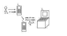
- the first wireless device 1 is moved closer to the second wireless device 2 after the user who has the first wireless device 1 such as a portable terminal selects data to be downloaded, and thereby the first wireless device
- wireless apparatus connect and transmits / receives data
- this is referred to as a pre-selection mode (first mode).
- an information KIOSK terminal corresponds to the second wireless device.
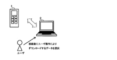
- the user selects data to be communicated after the first wireless device 1 and the second wireless device 2 are connected.
- data to be communicated since data to be communicated is selected after connection, it is called a post-selection mode (second mode).
- the first wireless device 1 may be a portable terminal
- the second wireless device 2 may be a PC or the like.
- the wireless system includes a first wireless device 1 and a second wireless device 2.
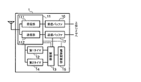
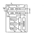
- wireless apparatus 1 is demonstrated using FIG.
- the first wireless device 1 transmits / receives a signal necessary for connection processing such as a connection request, or transmits / receives data, and the first wireless transmission device 11 transmits / receives data after completing the connection processing.
- a first timer 12 that counts the measurement time, and a control unit 13 that makes a pre-selection mode when the first measurement time is shorter than the first time T1, and a post-selection mode when the first measurement time is equal to or longer than the first time T1. And have.
- the first wireless device 1 includes a second timer 14 that counts a time that has elapsed since the wireless unit 13 transmitted / received data as a second measurement time, and a second elapsed time that is a second time in a pre-selection mode.
- the power supplied to the radio unit 11 is controlled, and even if the second elapsed time exceeds the third time T3 (T3> T2) in the post-selection mode,
- a power control unit 15 that controls power supplied to the wireless unit 11 when data is not received.
- the wireless unit 11 shifts to the sleep mode when the power supply control unit 13 controls the supply of power.
- the radio unit 11 of the first radio apparatus 1 includes a receiving unit 111 and a transmitting unit 112.
- the first radio apparatus has a reception buffer 16 that temporarily holds received data and a transmission buffer 17 that temporarily holds data to be transmitted.
- the reception unit 111 of the wireless unit 11 performs signal processing according to the wireless system, such as demodulation processing, decoding processing, anti-aliasing filter processing, frequency conversion processing, and low noise amplification processing, on the wireless signal received via the antenna. To generate a received signal.
- the received signal includes data, a connection request signal, a connection response signal, and the like.
- the reception unit 111 passes the reception signal to the reception buffer 116.
- the reception unit 111 stops operations other than performing carrier sense processing at intervals corresponding to the pre-selection mode or the post-selection mode.
- the reception unit 111 notifies the control unit 13 of the detected power value.
- the transmission unit 112 applies the transmission signal received from the transmission buffer 117 or the wake signal received from the control unit 13 to a wireless system such as modulation processing, encoding processing, waveform shaping filter processing, frequency conversion processing, and power amplification processing. According to the signal processing, a radio signal is generated. The radio signal is transmitted to the second radio apparatus 2 via the antenna.
- the transmission signal includes data, a connection request signal, a connection response signal, and the like.
- the transmission part 112 will stop operation
- the reception buffer 16 receives a reception signal from the reception unit 111 and temporarily holds the reception signal.
- the reception buffer 16 passes the held reception signal to an upper layer (not shown).
- the transmission buffer 17 temporarily holds a transmission signal received from an upper layer (not shown).
- the transmission buffer 17 notifies the control unit 13 to that effect.
- the transmission buffer 17 passes the held transmission signal to the transmission unit 112.
- the first timer 12 receives a measurement start notification from the wireless unit 11 when the connection process of the wireless unit 11 is completed. Specifically, when the first wireless device 1 transmits a connection response, a measurement start notification is received from the transmission unit 112, and when the first wireless device 1 receives a connection response, the measurement start notification is received from the reception unit 111.
- the first timer 12 that has received the measurement start notification starts measuring time.
- the first timer 12 transmits / receives data after the connection process is completed the first timer 12 receives a measurement end notification.
- the first wireless device 1 receives a measurement end notification from the transmission unit 112 when the data is transmitted, and from the reception unit 111 when the data is received.
- the first timer 12 ends the time measurement.
- the first timer 12 passes the measured time to the control unit 13 as the first measurement time.
- the second timer 14 measures the time elapsed since the wireless unit 11 transmitted / received the wireless signal as the second elapsed time.
- the second timer 14 receives a notification indicating that a radio signal has been received / transmitted from the receiving unit 111 or the transmitting unit 112 of the wireless unit 11, the second timer 14 starts measuring the second elapsed time.
- the second timer 14 resets the time that has been measured so far and starts measuring a new time. That is, the second timer 14 measures the time from when the wireless unit 11 receives / transmits a wireless signal until the next signal is received as the second elapsed time.
- the second timer 14 measures the time that has elapsed since the reception unit 111 performed the carrier sense processing in the sleep mode as the third elapsed time.
- the reception unit 111 performs the carrier sense process
- the reception unit 111 notifies the second timer 14 to that effect.
- the second timer 14 receives the notification, the second timer 14 starts measuring time.
- the second timer receives a notification that the carrier sense process has been performed
- the second timer resets the time that has been measured so far and starts measuring a new time. That is, the second timer 14 measures the carrier sense interval from when the receiving unit 111 performs the carrier sense process until the next carrier sense process is performed as the third elapsed time.
- the second timer 14 notifies the control unit 13 of the second elapsed time or the third elapsed time as the time measured at a constant interval.
- the control unit 13 controls whether the first wireless device 1 operates in either the pre-selection mode or the post-selection mode.
- the control unit 13 compares the first elapsed time with the first time T1.
- the first elapsed time is shorter than the first time T1, it is determined that the pre-selection mode is set. This is because the time to transmit / receive data after the connection process is completed is considered to be short because the data to be transmitted is determined in advance.
- the control unit 13 determines that the post-selection mode is set.
- control unit 13 When the control unit 13 receives the second elapsed time from the second timer 14, the control unit 13 compares the first elapsed time with the second time T2 or the third time T3.
- the second time T2 is shorter than the third time T3 (T2 ⁇ T3).
- the control unit 13 compares the second elapsed time with the second time T2. When the second elapsed time is longer than the second time T2, it is determined to shift to the sleep mode. In the post-selection mode, the control unit 13 compares the second elapsed time with the third time T3. When the third elapsed time is longer than the third time T3, it is determined to shift to the sleep mode. The control unit 13 notifies the power supply control unit 15 and the wireless unit 11 that the sleep mode is to be entered.
- the control unit 13 receives the third elapsed time from the second timer in the sleep mode.
- the control unit 13 compares the third elapsed time with the fourth time T4 or the fifth time T5.
- the fourth time T4 is shorter than the fifth time T5 (T4 ⁇ T5).
- the control unit 13 compares the third elapsed time with the fourth time T4. When the third elapsed time exceeds the fourth time T4, the control unit 13 instructs the reception unit 111 to perform carrier sense processing.
- the control unit 13 compares the third elapsed time with the fifth time T5. When the third elapsed time exceeds the fifth time T5, the control unit 13 instructs the reception unit 111 to perform carrier sense processing.
- the control unit 13 When receiving the power value as the carrier sense result from the receiving unit 111, the control unit 13 compares the power value with a threshold value. When the power value exceeds the threshold value, the control unit 13 notifies the power supply control unit 15 to end the sleep mode.
- control unit 13 When the control unit 13 receives a notification that the transmission signal is received from the upper layer from the transmission buffer 17 in the sleep mode, the control unit 13 determines the end of the sleep mode. The control unit 13 notifies the power supply control unit 15 that the sleep mode is to be ended. The control unit 13 generates a wake signal and passes the wake signal to the transmission unit 112.
- the power control unit 15 supplies power to each unit of the first radio apparatus 1 from a power unit (not shown).
- the power supply control unit 15 receives a notification from the control unit 14 to shift to the sleep mode, the power supply control unit 15 stops the power supply to the wireless unit 11 except when performing carrier sense processing.
- the power supply control unit 15 supplies power to the reception unit 111 when the control unit 11 instructs the reception unit 111 to perform carrier sense processing.
- the configuration of the second radio apparatus 2 is the same as that of the first radio apparatus 1, and thus the description thereof is omitted.
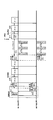
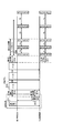
- FIG. 3 is a sequence diagram showing the operation of the wireless system in the preselection mode.
- the connection process is started when the first wireless device 1 transmits a connection request signal.
- the first wireless device 1 and the second wireless device 2 start connection processing by bringing the first wireless device 1 closer to the second wireless device 2. Specifically, the first radio apparatus 1 transmits a connection request signal to the second radio apparatus 2 (S11). When receiving the connection request signal, the second radio apparatus 2 returns a connection response signal (S12). Thereby, the connection process is completed.
- the first radio apparatus 1 measures the time from when the reception of the connection response signal is completed until the transmission unit 112 transmits data next as the first measurement time (S13). The first radio apparatus 1 compares the first measurement time with the first time T1. In this case, since the first measurement time is shorter than the first time T1, the first radio apparatus 1 determines the pre-selection mode.
- the second wireless device 2 measures the time from the completion of transmission of the connection response signal to the reception of data from the first wireless device 1 as the first measurement time (S14).
- the second radio apparatus 2 compares the first measurement time with the first time T1. In this case, since the first measurement time is shorter than the first time T1, the second radio apparatus 2 determines the pre-selection mode.
- the first radio apparatus 1 divides the data held in the transmission buffer 17 into a plurality of pieces, and transmits the divided data in bursts with a certain transmission interval (S15).
- the transmission interval is, for example, IFS (Inter Frame Space).
- To transmit in burst means to transmit data continuously at an interval of IFS + fourth time T4 or less.
- the first wireless device 1 transmits the divided data
- the first wireless device 1 starts measuring the second elapsed time from the completion of the transmission (S16).
- the second radio apparatus 2 starts measuring the second elapsed time from the completion of the reception (S17).
- the first and second wireless devices 1 and 2 do not receive data even after the second elapsed time T2 has elapsed, the first and second wireless devices 1 and 2 shift to the sleep mode (S18). In the sleep mode, the first and second radio apparatuses 1 and 2 perform carrier sense processing at intervals of the fourth time T4.
- transmission data is generated in the sleep mode, and data is transferred from the upper layer to the transmission buffer 17 of the first wireless device 1.
- the control unit 14 of the first radio apparatus 1 generates a wake signal.
- the transmission unit 112 of the first wireless device 1 transmits a wake signal to the second wireless device 2 (S19).
- the signal length Tw of the wake signal is not less than the fourth time T4 and shorter than the fifth time T5 (T4 ⁇ Tw ⁇ T5).
- the first wireless device 1 transmits the data held in the transmission buffer with a transmission interval (S20).
- the second wireless device 2 When the second wireless device 2 receives a wake signal during the carrier sense process, the second wireless device 2 ends the sleep mode. When receiving the wake signal, the second radio apparatus 2 receives data with a transmission interval. The first and second radio apparatuses 1 and 2 repeat the processing from step S15 to step S20 until the connection between the first and second radio apparatuses 1 and 2 is disconnected.
- the operation of the wireless system in the post-selection mode will be described with reference to FIG.
- the first and second wireless devices 1 and 2 are connected.
- the user selects data after the first and second wireless devices 1 and 2 are connected.
- the connection process is the same as that shown in FIG.
- the first radio apparatus 1 measures the time from when the reception of the connection response signal is completed until the transmission unit 112 transmits data next as the first measurement time (S23). The first radio apparatus 1 compares the first measurement time with the first time T1. In this case, since the first measurement time is equal to or longer than the first time T1, the first radio apparatus 1 determines the post-selection mode.
- the second wireless device 2 measures the time from the completion of transmission of the connection response signal to the reception of data from the first wireless device 1 as the first measurement time (S24).
- the second radio apparatus 2 compares the first measurement time with the first time T1. In this case, since the first measurement time is equal to or longer than the first time T1, the second radio apparatus 2 determines the post-selection mode.
- the first radio apparatus 1 divides the data held in the transmission buffer 17 into a plurality of pieces, and transmits the divided data in bursts with a certain transmission interval (S15).
- the first wireless device 1 transmits the divided data
- the first wireless device 1 starts measuring the second elapsed time from the completion of the transmission (S16).
- the second radio apparatus 2 starts measuring the second elapsed time from the completion of the reception (S17).
- the first and second wireless devices 1 and 2 do not receive data even when the second elapsed time has passed the third time T3, the first and second wireless devices 1 and 2 shift to the sleep mode (S28). In the sleep mode, the first and second radio apparatuses 1 and 2 perform carrier sense processing at a fifth time T5 interval.
- transmission data is generated in the sleep mode, and data is transferred from the upper layer to the transmission buffer 17 of the first wireless device 1.
- the control unit 14 of the first radio apparatus 1 generates a wake signal.
- the transmission unit 112 of the first wireless device 1 transmits a wake signal to the second wireless device 2 (S19). Since the second radio apparatus 2 performs carrier sense processing at intervals longer than the signal length Tw of the wake signal, the second radio apparatus 2 returns from the sleep mode even if the first radio apparatus 1 sends the wake signal once. May not. Therefore, the first radio apparatus 1 repeatedly transmits a wake signal until a response signal ACK to the wake signal is returned from the second radio apparatus 2 (S29).
- the second wireless device 2 When the second wireless device 2 detects the wake signal while performing the carrier sense process, the second wireless device 2 ends the sleep mode and transmits a response signal ACK to the wake signal (S21).
- the first radio apparatus 1 When receiving the response signal ACK, the first radio apparatus 1 transmits the data held in the transmission buffer (S20). The first and second radio apparatuses 1 and 2 repeat the processing from step S15 to step S20 until the connection between the first and second radio apparatuses 1 and 2 is disconnected.
- the wireless system selects data that the user wants to download before the first and second wireless devices 1 and 2 are connected (pre-selection mode) or whether the data is selected after being connected.
- the time for shifting to the sleep mode and the carrier sense interval are adjusted according to the (post-selection mode).
- the pre-selection mode since data to be transmitted is determined in advance, it is considered that a large amount of data is transmitted in a short period.
- the post-selection mode since data to be transmitted is determined each time, it is considered that data is transmitted irregularly over a long period of time.
- the power consumption is reduced and the carrier sense interval is shortened by finely shifting to the sleep mode.
- the return from the sleep mode can be shortened.
- the power consumption is reduced by increasing the carrier sense interval instead of increasing the time until shifting to the sleep mode.
- the sleep mode method is changed by switching between the pre-selection mode and the post-selection mode as described above, thereby reducing the power consumption of the system. Furthermore, the radio system according to the present embodiment switches between the pre-selection mode and the post-selection mode based on the first measurement time from connection processing to transmission / reception of the next data, thereby Even if the devices 1 and 2 do not exchange, the pre-selection mode and the hour / post-selection mode can be switched.
- the signal length of the wake signal Tw is set to be longer than the carrier sense interval in the pre-selection mode.
- the first radio apparatus 1 can start data transmission without receiving a response signal ACK to the wake signal in the pre-selection mode, and can shorten the interval from the return from the sleep mode to the data transmission.
- the first wireless device 1 uses the wake signal to return the second wireless device 2 from the sleep mode even in the post-selection mode, but the signal length is fifth. A signal longer than time T5 may be used. However, the first radio apparatus 1 can return the second radio apparatus 2 from the sleep mode in the shortest time corresponding to the signal length Tw of the wake signal by using the wake signal even in the post-selection mode.
- the first and second timers 12 and 14 pass the measured first to third elapsed times to the control unit 13, and the control unit 13 sets the first to third elapsed times and the first to fifth times.
- the first and second timers 12 and 14 compare the first to third elapsed times with the first to fifth times T1 to T5, and notify the control unit 13 of the comparison results. You may do it.
- the wireless system according to the present embodiment includes first and second wireless devices 3 and 4.
- the first and second radio apparatuses 3 and 4 have the same configuration as the first radio apparatus 1 shown in FIG. 2 except that a third timer 18 is provided.
- the wireless system according to the present embodiment is characterized by switching from the pre-selection mode to the post-selection mode when data is not transmitted / received even after the sixth time T6 has elapsed, when the mode is shifted to the sleep mode in the pre-selection mode. Yes.
- the configuration of the first wireless device 3 will be described with reference to FIG. 5.
- the third timer 18 of the first wireless device 3 starts measuring the fourth elapsed time when notified from the control unit 13 that the sleep mode is to be entered. To do.
- the third timer 18 notifies the control unit 13 of the fourth elapsed time at a constant cycle.
- control unit 13 When the control unit 13 receives the fourth elapsed time, the control unit 13 compares the fourth elapsed time with the sixth time T6. In the pre-selection mode, when the fourth elapsed time exceeds the sixth time T6, the control unit 13 switches from the pre-selection mode to the post-selection mode. The control unit 13 notifies the wireless unit 11 and the power supply control unit 15 of a switching notification indicating that the mode has been switched to the post-selection mode.
- the configuration of the second radio apparatus 4 is the same as that of the first radio apparatus 3, and thus the description thereof is omitted.
- the first, second wireless devices 3 and 4 that have shifted to the sleep mode start measurement of the fourth elapsed time by the third timer 18.
- the second timers 14 of the first and second radio apparatuses 3 and 4 start measuring the second elapsed time.
- wireless apparatuses 3 and 4 repeat a carrier sense process by 4th time T4 space
- both the first and second radio apparatuses 3 and 4 transmit and receive signals. If not performed, the control unit 13 of the first, second, and third radio apparatuses 3 and 4 switches from the pre-selection mode to the post-selection mode. When the first and second radio apparatuses 3 and 4 are switched to the post-selection mode, the carrier sense processing interval is set to the fifth time T5. The subsequent processing is the same as in the post-selection mode.
- the wireless system according to the second embodiment can obtain the same effects as the wireless system of the first embodiment, and is in the pre-selection mode even after a certain period of time has elapsed after shifting to the sleep mode.
- the power consumption can be further reduced by switching to the post-selection mode.
- the present invention is not limited to the above-described embodiment as it is, and can be embodied by modifying constituent elements without departing from the scope of the invention in the implementation stage.
- various inventions can be formed by appropriately combining a plurality of components disclosed in the embodiment. For example, some components may be deleted from all the components shown in the embodiment.
- constituent elements over different embodiments may be appropriately combined.
Landscapes
- Engineering & Computer Science (AREA)
- Computer Networks & Wireless Communication (AREA)
- Signal Processing (AREA)
- Mobile Radio Communication Systems (AREA)
Abstract
Description
本発明の第1実施形態に係る無線システムを説明する。無線システムは第1無線装置1と第2無線装置2とを有している。
本発明の第2実施形態に係る無線システムを説明する。本実施形態に係る無線システムは、第1,2無線装置3,4を有している。第1,2無線装置3,4は、第3タイマ18を有している点を除き、図2に示す第1無線装置1と同じ構成である。本実施形態に係る無線システムは、事前選択モードでスリープモードに移行した場合であって、第6時間T6経過してもデータを送受信しないときは事前選択モードから事後選択モードに切り替えることを特徴としている。
第1無線装置3の第3タイマ18は、制御部13からスリープモードに移行する旨の通知を受けると第4経過時間の計測を開始する。第3タイマ18は、一定周期で第4経過時間を制御部13に通知する。
Claims (4)
- 接続処理を行ってから通信相手とデータの送受信を行う無線装置であって、
前記データを受信する無線部と、
前記接続処理を完了してから前記データを送信又は受信するまでの第1測定時間をカウントするタイマと、
前記第1測定時間が前記第1時間T1より短い場合に前記第1モードと、前記第1測定時間が前記第1時間T1以上の場合に第2モードとする制御部と、
前記第1モードであって前記無線部が前記データを送信又は受信してから第2時間T2経過しても次のデータを受信しない場合に前記無線部に供給する電源を制御し、前記第2モードであって前記無線部が前記データを受信してから第3時間T3(T3>T2)経過しても次のデータを受信しない場合に前記無線部に供給する電源を制御する電源制御部と、を有し、
前記無線部は、前記電源制御部によって電源の供給を制御されることでスリープモードに移行することを特徴とする無線装置。 - 前記第1モードで前記スリープモードに移行した場合、第4時間T4間隔でキャリアセンスを行い、前記第2モードで前記スリープモードに移行した場合、第5時間T5(T5>T4)間隔でキャリアセンスを行うことを特徴とする請求項1記載の無線装置。
- データを格納するバッファをさらに有し、
前記無線部は、前記第1モードであって前記バッファに送信するデータが格納された場合、前記第4時間T4より長く、前記第5時間T5より短いwake信号を送信し、前記wake信号を送信してからIFS間隔あけて前記データを送信し、前記第2モードであって前記バッファに送信するデータが格納された場合、前記第4時間T4より長く、前記第5時間T5より短いwake信号を送信し、前記通信相手から前記wake信号に対する応答信号を受信した場合に前記データを送信することを特徴とする請求項2記載の無線装置。 - 前記制御部は、前記第1モードであって、前記スリープモードに移行してから第6時間経過してもデータを受信しない場合に前記第1モードから前記第2モードに切り替えることを特徴とする請求項3記載の無線装置。
Priority Applications (3)
| Application Number | Priority Date | Filing Date | Title |
|---|---|---|---|
| US13/583,803 US8811931B2 (en) | 2010-04-06 | 2010-04-06 | Radio apparatus |
| PCT/JP2010/002507 WO2011125118A1 (ja) | 2010-04-06 | 2010-04-06 | 無線装置 |
| JP2012509178A JP5475872B2 (ja) | 2010-04-06 | 2010-04-06 | 無線装置 |
Applications Claiming Priority (1)
| Application Number | Priority Date | Filing Date | Title |
|---|---|---|---|
| PCT/JP2010/002507 WO2011125118A1 (ja) | 2010-04-06 | 2010-04-06 | 無線装置 |
Publications (1)
| Publication Number | Publication Date |
|---|---|
| WO2011125118A1 true WO2011125118A1 (ja) | 2011-10-13 |
Family
ID=44762110
Family Applications (1)
| Application Number | Title | Priority Date | Filing Date |
|---|---|---|---|
| PCT/JP2010/002507 Ceased WO2011125118A1 (ja) | 2010-04-06 | 2010-04-06 | 無線装置 |
Country Status (3)
| Country | Link |
|---|---|
| US (1) | US8811931B2 (ja) |
| JP (1) | JP5475872B2 (ja) |
| WO (1) | WO2011125118A1 (ja) |
Families Citing this family (1)
| Publication number | Priority date | Publication date | Assignee | Title |
|---|---|---|---|---|
| JP7840394B2 (ja) | 2022-02-15 | 2026-04-03 | 楽天モバイル株式会社 | 複数の節電モードへのo-ruの切替え |
Citations (1)
| Publication number | Priority date | Publication date | Assignee | Title |
|---|---|---|---|---|
| JP2010045561A (ja) * | 2008-08-12 | 2010-02-25 | Toshiba Corp | 無線装置 |
Family Cites Families (2)
| Publication number | Priority date | Publication date | Assignee | Title |
|---|---|---|---|---|
| US20040057576A1 (en) | 2002-09-23 | 2004-03-25 | Simon Lavaud | System and method for on-demand battery backup for cable telephony device |
| JP4748053B2 (ja) * | 2005-12-27 | 2011-08-17 | パナソニック株式会社 | 無線通信システム |
-
2010
- 2010-04-06 JP JP2012509178A patent/JP5475872B2/ja not_active Expired - Fee Related
- 2010-04-06 US US13/583,803 patent/US8811931B2/en not_active Expired - Fee Related
- 2010-04-06 WO PCT/JP2010/002507 patent/WO2011125118A1/ja not_active Ceased
Patent Citations (1)
| Publication number | Priority date | Publication date | Assignee | Title |
|---|---|---|---|---|
| JP2010045561A (ja) * | 2008-08-12 | 2010-02-25 | Toshiba Corp | 無線装置 |
Also Published As
| Publication number | Publication date |
|---|---|
| US20130210367A1 (en) | 2013-08-15 |
| JP5475872B2 (ja) | 2014-04-16 |
| US8811931B2 (en) | 2014-08-19 |
| JPWO2011125118A1 (ja) | 2013-07-08 |
Similar Documents
| Publication | Publication Date | Title |
|---|---|---|
| JP5027955B2 (ja) | 無線通信装置、無線通信システムおよびチャネルの切替方法 | |
| JP4209809B2 (ja) | 無線通信システム | |
| RU2006139057A (ru) | Система и способ для периодического регулирования в режиме ожидания в системе связи с шбд | |
| JP2006500837A (ja) | 少なくとも一つの送信機及び/又は一つの受信機の動作を制御する方法、通信システム、及びその方法又はシステムの用法 | |
| JP2006005774A (ja) | 通信端末装置 | |
| JP2006173691A (ja) | 無線通信システム | |
| JP4081424B2 (ja) | 無線通信システムとその消費電力低減方法 | |
| JP5475872B2 (ja) | 無線装置 | |
| JP2005328439A (ja) | 情報通信システムの消費電力制御方法、その方法を用いた通信処理装置、および通信処理装置の消費電力制御プログラム | |
| US9489833B2 (en) | Remote control and communication method for remote control | |
| JP5254302B2 (ja) | 無線通信装置 | |
| CN1866759B (zh) | 无线通信装置以及无线通信方法 | |
| JP2019193077A (ja) | 無線通信装置およびその制御方法 | |
| JP2018038023A (ja) | 無線送受信システム | |
| US9398549B2 (en) | Wireless communication apparatus for establishing wireless connection using single operational mode for both transmission and reception of connection request and response signals, and method for same | |
| US20110113271A1 (en) | Method and device for the dynamic management of consumption in a processor | |
| JP2010212939A (ja) | 信号受信装置 | |
| JP2009141898A (ja) | 双方向無線システム | |
| JP4192113B2 (ja) | 無線通信システム | |
| WO2016208136A1 (ja) | 火災警報器および火災警報システム | |
| JP7151345B2 (ja) | 無線通信装置、時計及び無線通信プログラム | |
| JP4930223B2 (ja) | 無線通信システム、その送信側無線端末、受信側無線端末、プログラム | |
| CN101442690A (zh) | 节省通信装置耗电的侦测方法及其装置 | |
| JP4239025B2 (ja) | 通信端末装置及びその起動方法並びに通信システム | |
| JP2730553B2 (ja) | 単信方式無線送受信装置 |
Legal Events
| Date | Code | Title | Description |
|---|---|---|---|
| 121 | Ep: the epo has been informed by wipo that ep was designated in this application |
Ref document number: 10849366 Country of ref document: EP Kind code of ref document: A1 |
|
| WWE | Wipo information: entry into national phase |
Ref document number: 2012509178 Country of ref document: JP |
|
| NENP | Non-entry into the national phase |
Ref country code: DE |
|
| WWE | Wipo information: entry into national phase |
Ref document number: 13583803 Country of ref document: US |
|
| 122 | Ep: pct application non-entry in european phase |
Ref document number: 10849366 Country of ref document: EP Kind code of ref document: A1 |