WO2011122204A1 - 凸版印刷装置並びにそれを用いた印刷物及び有機エレクトロルミネッセンス素子の製造方法 - Google Patents
凸版印刷装置並びにそれを用いた印刷物及び有機エレクトロルミネッセンス素子の製造方法 Download PDFInfo
- Publication number
- WO2011122204A1 WO2011122204A1 PCT/JP2011/054638 JP2011054638W WO2011122204A1 WO 2011122204 A1 WO2011122204 A1 WO 2011122204A1 JP 2011054638 W JP2011054638 W JP 2011054638W WO 2011122204 A1 WO2011122204 A1 WO 2011122204A1
- Authority
- WO
- WIPO (PCT)
- Prior art keywords
- ink
- anilox roll
- relief
- plate
- printing apparatus
- Prior art date
- Legal status (The legal status is an assumption and is not a legal conclusion. Google has not performed a legal analysis and makes no representation as to the accuracy of the status listed.)
- Ceased
Links
Images







Classifications
-
- B—PERFORMING OPERATIONS; TRANSPORTING
- B41—PRINTING; LINING MACHINES; TYPEWRITERS; STAMPS
- B41F—PRINTING MACHINES OR PRESSES
- B41F5/00—Rotary letterpress machines
- B41F5/02—Rotary letterpress machines for printing on sheets
-
- B—PERFORMING OPERATIONS; TRANSPORTING
- B41—PRINTING; LINING MACHINES; TYPEWRITERS; STAMPS
- B41F—PRINTING MACHINES OR PRESSES
- B41F31/00—Inking arrangements or devices
- B41F31/02—Ducts, containers, supply or metering devices
- B41F31/022—Ink level control devices
-
- B—PERFORMING OPERATIONS; TRANSPORTING
- B41—PRINTING; LINING MACHINES; TYPEWRITERS; STAMPS
- B41F—PRINTING MACHINES OR PRESSES
- B41F31/00—Inking arrangements or devices
- B41F31/02—Ducts, containers, supply or metering devices
- B41F31/08—Ducts, containers, supply or metering devices with ink ejecting means, e.g. pumps, nozzles
-
- B—PERFORMING OPERATIONS; TRANSPORTING
- B41—PRINTING; LINING MACHINES; TYPEWRITERS; STAMPS
- B41F—PRINTING MACHINES OR PRESSES
- B41F35/00—Cleaning arrangements or devices
- B41F35/02—Cleaning arrangements or devices for forme cylinders
-
- B—PERFORMING OPERATIONS; TRANSPORTING
- B41—PRINTING; LINING MACHINES; TYPEWRITERS; STAMPS
- B41F—PRINTING MACHINES OR PRESSES
- B41F35/00—Cleaning arrangements or devices
- B41F35/04—Cleaning arrangements or devices for inking rollers
-
- B—PERFORMING OPERATIONS; TRANSPORTING
- B41—PRINTING; LINING MACHINES; TYPEWRITERS; STAMPS
- B41M—PRINTING, DUPLICATING, MARKING, OR COPYING PROCESSES; COLOUR PRINTING
- B41M1/00—Inking and printing with a printer's forme
- B41M1/02—Letterpress printing, e.g. book printing
- B41M1/04—Flexographic printing
-
- H—ELECTRICITY
- H10—SEMICONDUCTOR DEVICES; ELECTRIC SOLID-STATE DEVICES NOT OTHERWISE PROVIDED FOR
- H10K—ORGANIC ELECTRIC SOLID-STATE DEVICES
- H10K71/00—Manufacture or treatment specially adapted for the organic devices covered by this subclass
- H10K71/10—Deposition of organic active material
- H10K71/12—Deposition of organic active material using liquid deposition, e.g. spin coating
- H10K71/13—Deposition of organic active material using liquid deposition, e.g. spin coating using printing techniques, e.g. ink-jet printing or screen printing
-
- B—PERFORMING OPERATIONS; TRANSPORTING
- B41—PRINTING; LINING MACHINES; TYPEWRITERS; STAMPS
- B41M—PRINTING, DUPLICATING, MARKING, OR COPYING PROCESSES; COLOUR PRINTING
- B41M1/00—Inking and printing with a printer's forme
- B41M1/02—Letterpress printing, e.g. book printing
-
- B—PERFORMING OPERATIONS; TRANSPORTING
- B41—PRINTING; LINING MACHINES; TYPEWRITERS; STAMPS
- B41P—INDEXING SCHEME RELATING TO PRINTING, LINING MACHINES, TYPEWRITERS, AND TO STAMPS
- B41P2235/00—Cleaning
- B41P2235/10—Cleaning characterised by the methods or devices
- B41P2235/26—Spraying devices
Definitions
- the present invention relates to a relief printing apparatus that can form a fine pattern on a printing medium uniformly and with high positional accuracy by using a relief printing method or a resin relief printing, and that can be formed continuously and stably.
- high-definition patterns such as patterns in color filters for liquid crystal displays (LCD), light-emitting layers and charge transport layers of organic electroluminescence (EL) elements, electrode patterns on organic thin-film transistor (TFT) substrates, and shield patterns in electromagnetic wave shields
- the present invention relates to a printed material manufacturing method suitable for pattern formation.
- a photolithography method has been mainly used as a method of forming a fine pattern on a printing medium with a uniform in-plane and high positional accuracy by a wet process and further continuously and stably forming the pattern.
- this photolithography method has a problem that the process is complicated, the manufacturing equipment necessary for pattern formation is expensive, and the material is wasted, resulting in high manufacturing cost.
- a patterning method other than the photolithography method printing methods such as offset printing and letterpress printing, and ink jet methods are actually attempted to form a thin film pattern such as a light emitting layer formation of an organic EL element (prior art documents 1 and 2). ).
- the relief printing method is considered advantageous in terms of patterning accuracy with a thin film.
- Printing is completed by rotating the plate cylinder and transferring the ink on the relief plate to the substrate to be printed.
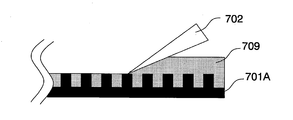
- the doctor blade makes the ink supplied from the anilox roll to the plate uniform to some extent, as shown in FIG. Therefore, excess ink on the anilox roll surface 701A is scraped off. In this way, the amount of ink held by the anilox roll is adjusted.
- anilox rolls and doctor blades are often made of metal from the viewpoint of accuracy and durability, and both are always in contact in the printing process, so the blade or anilox roll surface is gradually scraped and foreign matter is generated. If it is printed on paper, it will not be a big problem. However, in the case of electronic parts such as semiconductors and color filters, the product may be defective due to scraped foreign matter, or if the foreign matter is metal, it will cause a short circuit due to electrical conduction. Will occur.
- the amount of ink supplied to the letterpress surface greatly depends on the wettability of the plate surface, the pattern shape of the letterpress, the ink viscosity, the number of mesh lines of the anilox roll, and the cell volume (groove volume) of the mesh.
- the increase or decrease in the amount of ink supplied to the relief surface increases or decreases the print transfer film thickness to the substrate to be printed that is the final product.
- Patent Document 3 a printing apparatus that forms an ink coating on a solid roll and supplies it to the letterpress.
- Patent Document 3 a printing apparatus that forms an ink coating on a solid roll and supplies it to the letterpress.
- solid rolls it is difficult to control the film thickness of the ink transferred to the substrate to be printed because the film thickness cannot be controlled as in the case of anilox as described above, and electronics that require high film thickness accuracy and uniformity. Manufacturing parts was difficult.
- FIG. 15 when transferring the ink from the solid roll 710 to the relief 704, the ink coating film 711 penetrates into the depressions of the relief and the print pattern is crushed, so high-definition printing is difficult. It was.
- the ink is stored in the ink chamber and rotated to immerse a part of the anilox roll, so that it may have a role of ink application and drying prevention.
- this method there is a problem that the ink is exposed to the air in a large area, the ink is easily oxidized, and the dried foreign matter is generated.
- the ink stored in the chamber gradually deteriorates in the atmosphere not only when coating but also when the equipment is stopped, and it is necessary to replace this ink periodically in order to maintain product quality. There will be a large amount of consumption each time. Since the ink of the electronic material is expensive, unlike the printing ink, the running cost is increased.
- the anilox roll rotates, so that the ink is applied by passing through the chamber, coating the ink, scraping it with a doctor blade, and transferring it to the plate.
- the anilox roll rotates, so that it is difficult to select ink because it must have characteristics that allow simultaneous transfer.
- the object of the present invention is to reduce the contamination of the foreign matter caused by the printing apparatus into the print pattern, and to make the fine pattern uniform on the printing medium in a plane.
- An object of the present invention is to provide a relief printing apparatus and a printed matter manufacturing method that can be formed with high positional accuracy.
- the invention according to claim 1 which has been made to solve the above-mentioned problems, includes a rotary plate cylinder, a relief plate disposed on the plate cylinder, and an anilox roll that has an uneven surface and supplies ink to the relief plate. And a coating apparatus for forming an ink coating film by applying ink to the anilox roll surface.
- the invention according to claim 2 further comprises drying control means for controlling the drying state of the ink by promoting the volatilization of the solvent contained in the ink coating film on the anilox roll.
- the relief printing apparatus includes a control unit, and the control unit controls at least an ink application amount of the coating apparatus and a dry state of the ink.
- the invention described in claim 4 is provided with a moving mechanism for separating the relief printing plate and the anilox roll, and the drying control means is a drying mechanism that operates in a state where the relief printing plate and the anilox roll are separated.
- Item 4 The relief printing apparatus according to Item 2 or 3.
- the invention according to claim 5 is the mechanism according to any one of claims 2 to 4, characterized in that the drying means is a mechanism for generating an air flow in the region of the ink coating film to promote volatilization. It is a letterpress printing apparatus.
- the invention according to claim 6 is the relief printing according to any one of claims 2 to 4, wherein the drying means is a mechanism that promotes volatilization by making the area of the ink coating film low in pressure. Device.
- the invention according to claim 7 is the relief printing apparatus according to any one of claims 2 to 4, wherein the drying means heats the ink coating film by a far infrared irradiation device.
- the invention according to claim 8 is the relief printing apparatus according to any one of claims 1 to 4, further comprising an anilox cleaning mechanism for cleaning the anilox roll.
- the anilox cleaning mechanism may include a cleaning liquid supply unit that discharges the cleaning liquid to the anilox roll, a cleaning liquid removal unit that removes the cleaning liquid, an ink dissolved in the cleaning liquid, and an ink recovery unit that recovers the cleaning liquid.
- the invention according to claim 10 is the relief printing apparatus according to any one of claims 1 to 4, further comprising a plate washing mechanism for washing the relief plate.
- the invention described in claim 11 is a method for producing a printed matter, characterized in that it is produced using the relief printing apparatus according to any one of claims 1 to 10.
- the invention according to claim 12 is a method for producing a printed material in which ink is supplied onto a relief plate from an anilox roll having a concavo-convex surface, and the ink is transferred from the relief plate onto a printing substrate.
- the viscosity of the ink in the step of applying the ink to the surface of the anilox roll is 1 mPa ⁇ s to 15 mPa ⁇ s, and the viscosity of the ink in the step of transferring to the substrate to be printed is 30 mPa.
- the invention according to claim 14 is a method for producing an organic electroluminescent element, wherein a cathode and an anode, and an organic light emitting medium layer including at least an organic light emitting layer is sandwiched between a cathode and an anode on a substrate.
- an ink coating film is formed by adjusting the amount of ink by applying directly on the anilox roll by a coating apparatus instead of being immersed in an ink chamber as in the prior art. Therefore, it is possible to easily control the film thickness, and further, by using an anilox roll, it is possible to keep the film thickness stability and transferability to the plate constant.
- a drying control means for controlling the drying state of the ink film on the anilox it is possible to control the film thickness and the transfer state with the coating amount and the drying time, so that the printing film thickness with high accuracy can be controlled. Control is possible.
- an anilox cleaning mechanism it is possible to always keep the anilox roll in a state where it can be applied and transferred by washing and removing ink remaining on the anilox roll gradually during a long-term stoppage. It is possible to prevent the occurrence of dry ink foreign matter.
- a plate cleaning mechanism it is possible to wash and remove ink that has accumulated on the plate every time printing or ink that has adhered to the bottom of the pattern, it is possible to prevent adhesion of foreign matter, High quality printed matter can be produced.
- the ink coating on the anilox roll is controlled without using a doctor blade, and the ink is supplied to the anilox and the ink is transferred to the relief plate. By doing so, it is possible to produce a printed matter with less contamination of foreign matters and excellent film thickness accuracy.
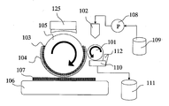
- FIG. 1 It is a schematic diagram of one structural example of the relief printing apparatus of this invention.
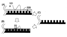
- A is a schematic diagram showing the ink coating film on the anilox roll surface immediately after the ink is applied from the coating device to the anilox roll.
- B is a schematic diagram showing an ink coating film on the anilox roll surface when transferring the ink from the anilox roll to the relief printing plate.
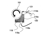
- It is a schematic diagram of an anilox roll periphery part of the example of 1 structure of the relief printing apparatus of this invention.
- FIG. 1 is a schematic diagram of a configuration example of a relief printing apparatus according to the present invention.
- the relief printing apparatus according to the present embodiment includes a substrate platen 106 on which a printing substrate is placed, a relief plate 104 that transfers ink to the printing substrate 107, and a rotation in which the relief plate 104 is mounted directly or with a cushion 103 interposed therebetween.
- a control controller for controlling these is provided.
- the configuration of the relief printing apparatus of the present invention is not limited to the configuration shown in FIG. For example, a method in which the substrate surface plate moves under the plate cylinder may be adopted, or a method in which the plate cylinder moves over the substrate surface plate may be employed.
- a coating film can be uniformly formed on the anilox roll, which is different from the conventional ink chamber in that the film thickness is controlled. Any method may be used as long as ink can be applied on the anilox roll 101 quantitatively without contact.
- the coating nozzle for ejecting ink is disposed so as to be parallel to the rotation axis of the anilox roll 101 and to face the anilox roll surface, and an ink coating film is formed on the anilox roll 101.
- Specific examples of such a coating apparatus include a slit coater.
- the slit coater 102 is a coating device that forms an ink coating film on the anilox roll 101 with a certain film thickness from a coating nozzle.
- the slit direction of the coating nozzle that discharges the ink of the slit coater is arranged so as to be parallel to the rotation axis of the anilox roll 101 and face the anilox roll surface, and an ink coating film is formed on the anilox roll surface 101A. Can do.
- a metering pump 108 is connected between the ink tank 109 and the coating apparatus for supplying ink to the coating apparatus 102.
- a controller (not shown) connected to the metering pump 108 controls the anilox roll 101 so that the metering pump 108 delivers ink of a specified film thickness at a coating rate that matches the rotation speed of the anilox roll 101. Coating is performed by synchronizing the pump with the rotation speed and controlling the amount of ink discharged from the coating head. With such a configuration, it is possible to accurately feed a specified film thickness for each printing.
- the ink is closed to prevent the ink from touching air except at the tip of the coating nozzle of the coating device, and the ink is pressurized to the pump.
- Nitrogen is also preferably used when supplying.
- the anilox roll 101 a known general anilox roll can be used.
- the amount of ink supplied to the relief printing plate was controlled by selecting the number of mesh lines of the anilox roll and the cell volume (groove volume) of the mesh, and the amount of ink transferred to the printing substrate was controlled.
- the controller can control the coating amount and drying state of the anilox roll in accordance with the ink characteristics, so that the film thickness can be arbitrarily changed. Therefore, it is not necessary to adjust the film thickness by changing the cell volume. By eliminating the need for a doctor blade, foreign matter is not mixed by the doctor blade, and high-quality printed matter can be manufactured.
- FIG. 2A is a schematic diagram showing an ink coating 220A on the anilox roll surface immediately after ink is applied from the coating apparatus 102 to the anilox roll.
- the ink ejected from the coating nozzle of the coating apparatus 102 onto the anilox roll 101 is applied at an ink concentration (medium ratio) that provides a viscosity that allows the cells on the anilox roll surface to be completely filled.
- the first viscosity of the ink at the time of coating is preferably 1 mPa ⁇ s or more and 15 mPa ⁇ s or less in order to form a uniform ink film thickness on the anilox roll surface 101A. If it is less than 1 mPa ⁇ s, the ink moves on the anilox roll surface 101A as the anilox roll rotates, and the ink film thickness may become non-uniform. When the viscosity exceeds 15 mPa ⁇ s, the ink may not be uniformly leveled on the anilox roll surface 101A during coating from the coating apparatus to the anilox roll.
- FIG. 2 (B) is a schematic diagram showing the ink coating 220B on the anilox roll surface when the ink is transferred from the anilox roll 101 to the relief plate 104.
- FIG. 2 (B) is a schematic diagram showing the ink coating 220B on the anilox roll surface when the ink is transferred from the anilox roll 101 to the relief plate 104.
- the ink film thickness and viscosity can be arbitrarily changed by controlling the dry state of the ink coating film 220B.
- the ink concentration increases due to the volatilization of the ink solvent, and the viscosity increases accordingly.
- the second viscosity of the ink at the time of transition to the relief is particularly preferably 30 mPa ⁇ s or more and 100 mPa ⁇ s or less.
- ink may flow into the concave portions of the relief printing plate. Therefore, considering the transfer characteristics from the relief printing plate to the printing substrate, a viscosity of 30 mPa ⁇ s or more is preferable. On the other hand, if it exceeds 100 mPa ⁇ s, ink may remain on the anilox roll 101 at the time of transfer, and the transfer amount may become unstable.
- the drying means for controlling the drying state it is possible to provide a time for volatilizing naturally by stopping the rotation of the anilox roll.
- the volatilization of the solvent may be promoted by reducing the partial pressure of the solvent around the anilox roll surface 101A by generating an air flow on the surface of the ink coating film.
- an anilox roll may be rotated, or an air blowing mechanism for supplying a gas such as air or an inert gas may be provided as the drying mechanism 113.
- a heating mechanism such as an infrared irradiation device or a far infrared irradiation device.
- Far infrared rays are preferred in order to uniformly heat the ink coating film and not to damage the ink material. Further, as will be described later, it is possible to employ a suction mechanism or the like that surrounds the ink coating film periphery and sucks the surrounding air to make the pressure low (including vacuum) and promote drying.
- the anilox roll 101 and the relief plate 104 are set in an asynchronous state.
- the plate cylinder 105 (the relief plate) and the anilox roll may be separated from the contact state.
- the plate cylinder 105 (letter plate) and the anilox roll are separated from the contact state as shown in FIG. A region where the anilox roll does not contact may be provided.
- a notch region is provided in the plate cylinder.
- an anilox roll moving mechanism 130 that mechanically moves the distance between the plate cylinder 105 and the anilox roll 101 may be provided, and the moving mechanism may be connected to a control controller. According to a command from the controller, the relief printing plate and the anilox roll can be automatically separated during the drying process, and can be automatically brought into contact with each other during the ink transfer process to the relief printing plate.
- the ink coating film 320 is opposed to the drying mechanism 113 by rotating the anilox roll as long as the anilox roll 101 is arranged at least at a predetermined anilox roll moving position. It can be matched to the area to be. Therefore, the position where the anilox roll and the drying mechanism are opposed is also arbitrary. For example, in the form of FIG. 3, it arrange
- the anilox roll moving mechanism 112 may be a mechanism that moves integrally with the coating apparatus 102 and the drying mechanism 114, or only the anilox roll 101 may be moved. However, a mechanism that moves the coating apparatus 102 and the anilox roll 101 together is preferable for the stability of ink coating.
- the ink density is adjusted on the anilox roll, the ink density is changed due to the difference between the density of the ink remaining without transferring to the relief plate 104 after the previous printing and the density of the ink newly supplied from the coating apparatus 102.
- the state of the ink transferred to the letterpress may not be kept constant due to variations.
- an anilox cleaning mechanism 114 for cleaning the anilox roll 104 for each printing process may be provided.
- the step of cleaning the anilox roll between the step of transferring the ink to the relief plate 104 and the step of supplying the ink onto the anilox roll again, it is possible to eliminate variations in the ink density. That is, a cycle of supplying ink onto the anilox roll (FIG. 5A), transferring ink to the relief plate (FIG. 5B), removing ink on the anilox roll surface 101A (FIG. 5C), and supplying ink onto the anilox roll (FIG. 5A).
- the ink state can be maintained appropriately.
- an anilox roll cleaning unit 112 having at least a cleaning liquid discharged toward the anilox surface and a cleaning liquid discharging means for washing away ink and a cleaning liquid removing means for removing the cleaning liquid; And an ink recovery unit 110 for recovering the washed ink and cleaning liquid.
- the anilox roll cleaning unit 113 preferably has a configuration that does not come into contact with the anilox roll except for the cleaning liquid in order to prevent the anilox roll from being damaged or foreign matter from entering.
- the cleaning liquid for cleaning the anilox 101 is preferably a volatile organic solvent that is soluble in the ink medium (ink material). This is because if water or a detergent is mixed, the ink characteristics may be adversely affected if it remains on the anilox surface. Further, by using a volatile organic solvent, it is possible to remove the cleaning liquid from the anilox 101 without leaving the cleaning liquid by blowing pressurized gas. In particular, in order not to adversely affect the properties of the ink, it is preferable to use the same organic solvent as the ink solvent or an organic solvent in which one or several of the organic solvents included in the ink solvent are easily mixed as the cleaning liquid. .
- FIG. 6 is a schematic view of an anilox roll cleaning mechanism 114 portion of the relief printing apparatus according to the present invention.
- the cleaning mechanism 114 shown in FIG. 6 at least a cleaning liquid supply unit 116 that supplies the cleaning liquid to the anilox roll surface, a cleaning liquid recovery unit 117 that recovers the cleaning liquid supplied to the anilox roll surface without splashing, and a cleaning liquid from the anilox roll surface.
- a blower unit 115 for drying and removing is provided.
- the anilox roll and the coating apparatus 102 face each other after the position where the anilox roll 101 and the letterpress come into contact with the rotation direction of the anilox roll (arrow in the figure). It is installed in the area before the position.
- the cleaning liquid injection nozzle 116 As the form of the cleaning liquid injection nozzle 116, the form in which the anilox roll 101 is arranged in parallel in the width direction (direction parallel to the rotation axis), the form in which the cleaning liquid injection nozzle moves in the width direction of the anilox roll, the width of the anilox roll A slit nozzle configuration that can supply the cleaning liquid uniformly in the direction is conceivable. Further, a two-fluid nozzle that ejects the cleaning liquid together with the pressurized gas may be used in order to scrape the ink residue accumulated in the recess (cell) of the anilox roll. Similarly, the cleaning liquid spray nozzle 116 ejects ink residue accumulated in the recess of the anilox roll, so that the cleaning liquid spray nozzle 116 is efficiently arranged at an angle perpendicular to the anilox roll surface or inclined downward.
- the blower unit 115 is removed by blowing or volatilizing the cleaning liquid on the anilox roll 101 by the cleaning liquid supply unit 116.
- the gas injection nozzle 115a which injects pressurized gas on the surface of the anilox roll supplied with the cleaning liquid, and this gas injection nozzle is connected to the pressurized gas supply hose 115b, and pressurizes. Pressurized gas is supplied from the gas supply hose.
- the pressurized gas used is preferably air or an inert gas such as nitrogen or a rare gas.
- the gas injection nozzle is directed to the anilox roll 101 by the coating apparatus 102 in the rotation direction of the anilox roll. It is arranged at a position closer to the application position.
- a nozzle for injecting a cleaning liquid onto the surface of the anilox roll 101 and an pressurized gas is injected into the anilox roll after the cleaning liquid is supplied.
- the nozzle may be a single common nozzle 121, and the cleaning liquid supply hose 116b and the pressurized gas supply hose 115b may be connected to the common nozzle. You may comprise so that a washing
- the cleaning liquid recovery unit 117 has a cleaning liquid recovery tray 119 and a suction port 118 communicating with the bottom of the tray 119, and this suction port is connected to a suction hose and further sucked.
- the cleaning liquid is collected in the ink collection tank 112 connected to the hose. Since the ink is dissolved in the collected cleaning liquid, the ink can be regenerated and reused. For this reason, an expensive ink material is not wasted and the cost can be reduced.
- the anilox roll cleaning mechanism 114 has a cleaning mechanism cover 120 that accommodates a cleaning liquid injection nozzle and a gas injection nozzle or a common nozzle and a tray 120, and a location corresponding to the outer peripheral curved surface of the anilox roll 101 of the cover 120. Is formed in a curved surface shape corresponding to the outer peripheral curved surface of the anilox roll, and the curved surface portion 120A of the cleaning mechanism cover 120 is opened. Since the cleaning mechanism cover 120 covers the nozzles of the blower unit and the cleaning liquid supply unit and the cleaning liquid recovery unit 117, it is possible to perform the cleaning process without splashing the cleaning liquid and to prevent foreign substances from entering.
- the gap between the outer peripheral curved surface of the anilox roll and the curved surface-shaped portion 120A is preferably 5 mm or less. Further, as shown in FIG. 4, the cleaning liquid supply nozzle and the gas injection nozzle are arranged back and forth in the rotation direction of the anilox roll so as to face the opening of the curved surface portion.
- the cleaning cover 120 covers a region of the anilox surface, so that the surrounding air is sucked by the suction port 118 of the cleaning liquid recovery unit 117 or a suction nozzle provided separately, and the region is in a low-pressure state.
- the volatilization removal of the cleaning liquid in the cleaning process can be promoted.
- the drying mechanism 113 may be used alone, or may be configured to include the blower unit 115 and used in combination.
- the drying device 113 and the cleaning mechanism 114 are arranged apart from each other, and the moving mechanism 112 is used to move from the plate cylinder side to the operating position. In this case (FIG. 8B), it is easy to use the functions of the drying device 113 and the cleaning mechanism 114 together.
- a plate cleaning unit 125 for cleaning the relief plate 104 at regular intervals may be provided in order to keep the ink characteristics constant.
- the plate cleaning unit 125 can use the same configuration as the anilox roll cleaning mechanism 114.
- a plate cylinder and a mechanism in which the anilox and the anilox cleaning mechanism 114 are relatively moved may be provided, and the cleaning unit and the cleaning liquid recovery unit may be used in combination.
- the inside thereof may be filled with an inert gas such as nitrogen.
- inert gas such as nitrogen.
- Ink materials used in electronic products often react with oxygen in the atmosphere and oxidize, and it is considered that problems such as deterioration of product characteristics occur due to deterioration of the ink material. Therefore, by covering the entire device with a cover, it is sealed with an inert gas such as nitrogen, and by reducing the oxygen concentration around the device, the oxidation of the ink can be suppressed and the characteristic deterioration of the printed product can be prevented. it can. Further, since the ink does not oxidize, it is easy to regenerate and reuse the ink from the collected cleaning liquid.
- the entire apparatus may be sealed and connected to a vacuum pump, and printing may be performed in a vacuum or in a low pressure state in which air is replaced with an inert gas.
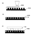
- a part of the ink solvent is volatilized on the anilox to change from the first viscosity to the second viscosity (FIG. 9 (b)).
- known drying methods such as natural drying, heat drying, and vacuum (low pressure) drying can be used.
- the film thickness of the ink coating 220B on the anilox surface 101A when transferring ink to the relief plate 104 depends on the relief depth and pattern of the relief plate, but the film thickness h from the projection on the anilox surface is the cell depth. It is preferable that it is 1/10 or less.
- the amount of ink supplied to the ink convex portion may not be stable, or the ink may enter the concave portion of the relief plate like a solid roll.
- the liquid surface of the ink coating film in the cell is preferably equal to or higher than the height of the convex portion on the anilox roll surface, that is, h ⁇ 0, in order to contact the convex portion of the relief plate.
- the relief formed on the relief printing plate is prepared by synchronizing the rotational speed with the plate cylinder 105 equipped with the relief printing plate 220B, which is suitable for the transfer process for transferring the ink from the anilox roll 101 to the relief printing plate 104 as described above.
- the ink rotates (primary transfer) from the anilox roll to the relief plate in a range corresponding to the pattern area (FIG. 9C).
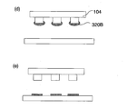
- the platen and the surface plate 106 on which the printing substrate 107 is installed are synchronized, and the relief pattern is brought into contact with the printing substrate 107 and rotated to transfer the ink pattern corresponding to the relief pattern to the printing substrate ( Secondary transfer is performed to form an ink pattern on the substrate to be printed (FIGS. 10D and 10E).
- an anilox cleaning step can be provided as shown in FIG.
- the anilox roll 101 is provided with the moving mechanism 130 and is washed away from the relief printing plate, it is possible to work in parallel.
- the anilox roll 101 is further rotated, and the region where the ink 220C remains on the anilox roll surface is moved to the cleaning mechanism 114.
- printing may be performed continuously with the anilox roll and the plate cylinder synchronized, or cleaning may be performed by rotating only the anilox roll asynchronously.
- the anilox roll 101 is further rotated, and the cleaning of the anilox roll is completed from the coating device to the point where the ink coating film is formed on the anilox roll surface.
- the ink and the cleaning liquid are completely removed from the anilox roll surface. In this state, new ink can be applied.
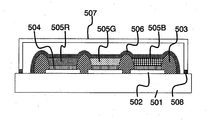
- FIG. 12 showing a configuration example of an organic EL element.
- the organic EL element of the present invention can be applied to both a passive matrix type organic EL element and an active matrix type organic EL element.
- the passive matrix method is a method in which stripe-shaped electrodes are opposed to each other so as to be orthogonal to each other, and light is emitted at the intersection, whereas the active matrix method uses a so-called thin film transistor (TFT) substrate in which a transistor is formed for each pixel. Thus, the light is emitted independently for each pixel.
- TFT thin film transistor
- the organic EL element is a bottom emission type organic EL element that extracts light from the substrate side, it is necessary to use a transparent substrate, but in the case of the top emission type that extracts light from the opposite side of the substrate The substrate need not be translucent.
- a glass substrate or a plastic film or sheet can be used as the substrate 501. If a plastic film is used, a polymer EL element can be produced by winding, and a display panel can be provided at a low cost.
- a plastic film for example, polyethylene terephthalate, polypropylene, cycloolefin polymer, polyamide, polyethersulfone, polymethyl methacrylate, polycarbonate, or the like can be used.
- these films are barrier layers made of metal oxides such as silicon oxide showing water vapor barrier properties and oxygen barrier properties, oxynitrides such as silicon nitride, polyvinylidene chloride, polyvinyl chloride, saponified ethylene-vinyl acetate copolymers. Is provided as necessary.
- metal oxides such as silicon oxide showing water vapor barrier properties and oxygen barrier properties
- oxynitrides such as silicon nitride, polyvinylidene chloride, polyvinyl chloride, saponified ethylene-vinyl acetate copolymers. Is provided as necessary.
- a pixel electrode 2 patterned as an anode is provided on the substrate 501.
- transparent electrode materials such as ITO (indium tin composite oxide), IZO (indium zinc composite oxide), tin oxide, zinc oxide, indium oxide, and aluminum oxide composite oxide can be used.
- ITO is preferred because of its low resistance, solvent resistance, transparency, and the like.
- ITO is formed on the substrate by sputtering and patterned by photolithography to form line-shaped pixel electrodes 502. Then, after forming the line-shaped pixel electrode 2, an insulating layer 503 is formed by a photolithography method using a photosensitive material between adjacent pixel electrodes.
- the insulating layer 503 in this embodiment preferably has a thickness in the range of 0.5 ⁇ m to 5.0 ⁇ m.
- the spread of the hole transport ink printed on each pixel electrode is suppressed, and leaks due to the presence of the hole transport layer on the insulating layer when a display is made. Generation of current can be prevented. If the insulating layer is too low, ink spreading cannot be prevented and a hole transport layer is formed on the insulating layer.
- a cathode layer is formed by directing the insulating layer.
- the cathode layer is formed so as to straddle the insulating layer in this way, if the insulating layer is too high, the cathode layer is disconnected, resulting in a display defect.
- the height of the insulating layer exceeds 5.0 ⁇ m, disconnection of the cathode tends to occur.
- the photosensitive material for forming the insulating layer 503 may be either a positive resist or a negative resist, and may be a commercially available one, but it must have insulating properties. Note that if the partition does not have sufficient insulation, a current flows to the adjacent pixel electrode through the partition and a display defect occurs. Specific examples thereof include polyimide, acrylic resin, novolac resin, and fluorene, but are not limited thereto. Further, for the purpose of improving the display quality of the organic EL element, a light shielding material may be included in the photosensitive material.
- the photosensitive resin for forming the insulating layer 503 is applied using a coating method such as a spin coater, a bar coater, a roll coater, a die coater, or a gravure coater, and patterned by a photolithography method.
- a coating method such as a spin coater, a bar coater, a roll coater, a die coater, or a gravure coater
- the insulating layer may be formed using a gravure offset printing method, a reverse printing method, a relief printing method, or the like without using a photosensitive resin.
- the hole transport layer 504 is formed next.
- the hole transport material forming the hole transport layer 4 include polyaniline derivatives, polythiophene derivatives, polyvinylcarbazole (PVK) derivatives, poly (3,4-ethylenedioxythiophene) (PEDOT), and the like. These materials are dissolved or dispersed in a solvent to form a hole transport material ink, which can be formed using the relief printing method according to the present embodiment.
- Examples of the solvent for dissolving or dispersing the hole transport material include toluene, xylene, acetone, methyl ethyl ketone, methyl isobutyl ketone, cyclohexanone, methanol, ethanol, isopropanol, ethylene glycol, propylene glycol, polyethylene glycol, glycerin, and ethyl acetate.
- the solid content concentration of the hole transport layer ink is preferably 0.5 to 4.0%. This is because the hole transport ink used in the present embodiment is not stable at a concentration of 4.0% or more, and causes ink aggregation and hole transport layer unevenness.
- an inorganic material may be used for the hole transport layer 504.
- the inorganic material include Cu 2 O, Cr 2 O 3 , Mn 2 O 3 , FeOx (x to 0.1), NiO, CoO, and Pr 2.
- O 3 Ag 2 O, MoO 2 , Bi 2 O 3 , ZnO, TiO 2 , SnO 2 , ThO 2 , V 2 O 5 , Nb 2 O 5 , Ta 2 O 5 , MoO 3 , WO 3 , MnO 2, etc.
- These transition metal oxides and inorganic compounds containing one or more of these nitrides and sulfides can be used.
- a dry film forming method such as a resistance heating vapor deposition method, an electron beam vapor deposition method, a reactive vapor deposition method, an ion plating method, a sputtering method, or a spin coating method is used.
- An existing film formation method such as a wet film formation method such as a sol-gel method can be used.
- the organic light emitting layer is a layer that emits light by passing an electric current.
- the organic light emitting material forming the organic light emitting layer is, for example, a coumarin type, a perylene type, a pyran type, an anthrone type, a porphyrene type, a quinacridone type, N, N ′.
- a luminescent dye such as dialkyl-substituted quinacridone, naphthalimide, N, N′-diaryl-substituted pyrrolopyrrole, iridium complex, etc. dispersed in a polymer such as polystyrene, polymethylmethacrylate, polyvinylcarbazole, Examples thereof include polyarylene-based, polyarylene vinylene-based, and polyfluorene-based polymer materials.
- organic light emitting materials are dissolved or stably dispersed in a solvent to form an organic light emitting ink.
- the solvent for dissolving or dispersing the organic light-emitting material include toluene, xylene, acetone, anisole, methyl ethyl ketone, methyl isobutyl ketone, cyclohexanone, or a mixed solvent thereof.
- aromatic organic solvents such as toluene, xylene, and anisole are preferable from the viewpoint of solubility of the organic light emitting material.
- a surfactant, an antioxidant, a viscosity modifier, an ultraviolet absorber, and the like may be added to the organic light emitting ink as necessary.
- the organic light emitting layer 505 As a method for forming the organic light emitting layer 505, when using a letterpress printing method, a resin letterpress suitable for organic light emitting ink can be used, and among these, a water developing type photosensitive resin letterpress is preferable. As shown in FIG. 12, for example, when the organic light emitting layer (505R, 505G, 505B) is applied in multiple colors so as to correspond to RGB emission colors, the manufacturing method of the present invention capable of forming a high-definition pattern is suitable. It is.
- the cathode layer 506 is formed in a line pattern orthogonal to the line pattern of the pixel electrode.
- a material according to the light emitting characteristics of the organic light emitting layer can be used.
- a simple metal such as lithium, magnesium, calcium, ytterbium, and aluminum or a stable metal such as gold and silver can be used. And alloys thereof.
- a conductive oxide such as indium, zinc, or tin can be used.
- Examples of the method for forming the cathode layer include a method using a vacuum vapor deposition method using a mask.
- the organic EL element of the present embodiment has a structure in which a hole transport layer and an organic light emitting layer are laminated from the anode layer side between a pixel electrode that is an anode and a cathode layer.
- the organic light emitting layer which contributes to light emission should just be provided in between.
- a laminated structure in which a light emitting medium layer such as a hole blocking layer, an electron transport layer, and an electron injection layer is selected as necessary can be formed between the anode layer and the cathode layer.
- the formation method of the present invention can also be used when forming these layers.
- a glass cap 507 and an adhesive 508 can be hermetically sealed to obtain an organic EL element.
- sealing may be performed using a sealing agent and a flexible film.
- an example in which the method for producing a printed material according to the present invention is applied to the formation of an organic light emitting layer and a light emitting medium layer in an organic EL element is shown as an example of a printed body.
- LCD liquid crystal display
- EL organic electroluminescence
- TFT organic thin film transistor
- Example 1 (Letter printing machine)
- the configuration of the apparatus used in this embodiment is the same as the configuration shown in FIG. 1, and a rotary plate cylinder 105 to which a relief plate for pattern formation is mounted via a block cushion 103, A substrate surface plate 106 on which the printed circuit board 107 is placed, an anilox roll 101 for supplying ink to the relief plate 104, a slit coater 102 for applying ink to the anilox roll, and ink to the slit coater.
- the relief plate 104 is made of a nickel material having a thickness of 250 ⁇ m as a base material, and a photosensitive resin containing water-soluble polyamide as a main component is patterned on the base material using a photolithographic method so that the width is 90 ⁇ m and 450 ⁇ m. It is formed in a pitch stripe shape.
- An active matrix substrate provided with 502 was used.
- the pixel size is 130 ⁇ m ⁇ 450 ⁇ m.
- the partition wall 503 was formed in such a shape as to cover the edge of the pixel electrode provided on the active matrix substrate and partition the pixel.
- the partition wall is formed by applying a positive resist ZWD6216-6 manufactured by ZEON Corporation on the entire surface of the active matrix substrate with a spin coater so as to have a dry thickness of 1 ⁇ m, and then photolithography to form a line width on four sides of each pixel portion. A 20 ⁇ m partition wall was formed.
- a poly- (3,4) -ethylenedioxythiophene / polystyrene sulfonic acid (PEDOT / PSS) 1.5 wt% aqueous solution having a thickness of 100 nm was formed as a hole transport layer on the pixel electrode by spin coating. . Further, the PEDOT / PSS thin film thus formed was dried at 100 ° C. for 1 hour under reduced pressure to produce a printed substrate 107.
- PEDOT / PSS polystyrene sulfonic acid
- the following organic light-emitting inks composed of three colors of red, green, and blue (R, G, B) were prepared by dissolving in xylene.
- the red light-emitting ink (R) is a toluene solution of a polyfluorene derivative (a red light-emitting material manufactured by Sumitomo Chemical Co., Ltd., trade name Red 1100).
- the green light emitting ink (G) is a toluene solution of a polyfluorene derivative (green light emitting material manufactured by Sumitomo Chemical Co., Ltd., trade name Green 1300).
- the blue light emitting ink (B) is a toluene solution of a polyfluorene derivative (blue light emitting material manufactured by Sumitomo Chemical Co., Ltd., trade name Blue 1100).
- the viscosity (first viscosity) of each ink solution is 1.5 mPa ⁇ s.
- the organic light-emitting ink having the first viscosity was supplied to the ink tank 109 of the relief printing apparatus, and applied from the coating apparatus 102 onto the 600 line / inch honeycomb anilox roll 101.
- a part of the ink solvent was volatilized by rotating the anilox roll while the plate cylinder and the anilox roll were asynchronous. After rotating for a certain period of time, when the ink viscosity (second viscosity) reaches 33 mPa ⁇ s, the anilox roll and the letterpress are brought into contact with each other to synchronize the two, and the ink is transferred from the anilox roll to the convex part of the letterpress. I let you.
- the ink pattern was transferred while pressing the relief plate against the printing substrate 106 to form a stripe pattern of the organic light emitting layer 505 on the printing substrate 107. Thereafter, the anilox roll was further rotated, and the anilox roll cleaning unit 112 was made to coincide with the area where the anilox roll ink was applied, and the anilox roll was cleaned.
- the ink and cleaning liquid were collected in the collection tank 111 by the ink collection unit 110. Further, the light emitting layer pattern was printed several times on another substrate to be printed, and finally the anilox roll cleaning by the anilox roll cleaning unit 112 and the plate cleaning by the plate cleaning unit 125 were performed.
- the organic light emitting layer pattern was obtained by repeating this process for each of the red organic light emitting layer, the green organic light emitting layer, and the blue organic light emitting layer. After printing for each color, drying was performed in an oven at 130 ° C. for 1 hour.
- Examples 2 to 4 Subsequently, as Examples 2 to 4, the first viscosity of the organic light emitting ink is changed in the range of 1 mPa ⁇ s to 15 mPa ⁇ s, and the second viscosity is in the range of 30 mPa ⁇ s to 100 mPa ⁇ s.
- An organic electroluminescence element was produced in the same manner as in Example 1 except that the above was changed.
- Comparative Examples 1 to 4 were carried out except that the first viscosity of the organic light emitting ink was less than 1 mPa ⁇ s or greater than 15 mPa ⁇ s, or the second viscosity was less than 30 mPa ⁇ s or greater than 100 mPa ⁇ s.
- An organic electroluminescence device was produced in the same manner as in Example 1. A table summarizing Examples 1 to 4 and Comparative Examples 1 to 4 is shown below.
- the first viscosity of the organic light emitting ink is changed in the range of 1 mPa ⁇ s to 15 mPa ⁇ s, and the second viscosity is in the range of 30 mPa ⁇ s to 100 mPa ⁇ s.
- the organic light emitting layer was successfully formed by printing.
- Comparative Example 1 since the first viscosity was too low, the ink moved on the anilox roll, resulting in a non-uniform ink film thickness, and film thickness unevenness occurred in the organic light emitting layer after the printing process.
- Comparative Example 5 a relief printing apparatus in which a plate washing unit 125 for washing the relief plate was added to the configuration shown in FIG. 13 was used. That is, the relief plate 4, the rotary plate cylinder 5 on which the relief plate 4 is mounted via the underlay cushion 3, the anilox roll 1 for supplying ink to the plate surface of the relief plate 4, and the ink to the anilox roll 1 are supplied. And a substrate surface plate 6 on which a substrate 7 to be printed is placed, and a letterpress printing apparatus configured to have an ink chamber 8 to be removed, a doctor blade 2 for scraping off excess ink on an anilox roll.
- the relief plate 104 and the substrate to be printed were produced in the same procedure as in Example 1.
- the following organic light-emitting inks composed of three colors of red, green, and blue (R, G, B) were prepared by dissolving in xylene.
- the red light-emitting ink (R) is a toluene solution of a polyfluorene derivative (a red light-emitting material manufactured by Sumitomo Chemical Co., Ltd., trade name Red 1100).
- the green light emitting ink (G) is a toluene solution of a polyfluorene derivative (green light emitting material manufactured by Sumitomo Chemical Co., Ltd., trade name Green 1300).
- the blue light emitting ink (B) is a toluene solution of a polyfluorene derivative (blue light emitting material manufactured by Sumitomo Chemical Co., Ltd., trade name Blue 1100).
- the viscosity of each ink solution is 60 mPa ⁇ s.
- the above organic light-emitting ink is supplied to an ink tank of a typographic printing press, applied to a honeycomb anilox roll 701 of 600 lines / inch from an ink chamber 708, scraped by a doctor 702, and then applied to a convex portion of a relief plate 704. Inked. Further, the intaglio relief plate 104 was pressed against the substrate to be printed and transferred to form a stripe pattern on the substrate to be printed. After washing the printing machine in the same manner as in the example, this step was repeated for each of the red organic light emitting layer, the green organic light emitting layer, and the blue organic light emitting layer to obtain an organic light emitting layer pattern. After printing for each color, drying was performed in an oven at 130 ° C. for 1 hour.
- Example 1 emitted light uniformly on all the substrates, but in the comparative example, dark spots were generated on a plurality of substrates. Further, after the organic light emitting layer was formed, the amount of foreign matter mixed in the light emitting layer was inspected before sealing. The inspection was performed using an inspection apparatus capable of detecting a foreign matter size up to 2 ⁇ m using a CCD camera. In the inspection, the amount of foreign matter in Example 1 and the comparative example was calculated by scanning with 12 pixels ⁇ 9 pixels in one frame.
- Example 1 the maximum amount of foreign matter was 6345 and the average was 663, whereas in the comparative example, the maximum was 84706 and the average was 22409 foreign matters, which is the reason for this. For example, it has been found that a highly accurate pattern can be formed without using a doctor blade, and the amount of foreign matter can be stably reduced.
Landscapes
- Engineering & Computer Science (AREA)
- Mechanical Engineering (AREA)
- Manufacturing & Machinery (AREA)
- Electroluminescent Light Sources (AREA)
- Printing Methods (AREA)
- Inking, Control Or Cleaning Of Printing Machines (AREA)
Abstract
Description
図2の凸版印刷装置では、印刷パターンに対応した凸形状のパターンを有する凸版704と、版下クッション703を介して凸版704が装着される回転式の版胴705と、凸版704の版面にインクを供給するためのアニロックスロール701と、アニロックスロール701にインクを供給するインクチャンバー708と、アニロックスロール上の余分なインクを掻き落とすドクターブレード702と、被印刷基板707が載置される基板定盤706と、を有して構成されている。版胴を回転させて、凸版上のインクを被印刷基板に転写することで、印刷が完了する。
また、請求項2記載の発明は、アニロックスロール上の前記インク塗膜に含まれる溶媒の揮発を促進させてインクの乾燥状態を制御する乾燥制御手段を備えることを特徴とする請求項1に記載の凸版印刷装置である。
また、請求項3記載の発明は、前記凸版印刷装置は制御手段を備え、制御手段は、少なくとも塗工装置のインク塗布量と、インクの乾燥状態を制御することを特徴とする請求項2に記載の凸版印刷装置である。
また、請求項4記載の発明は、凸版とアニロックスロールを離間させる移動機構を備え、前記乾燥制御手段は、凸版とアニロックスロールを離間させた状態で動作する乾燥機構であることを特徴とする請求項2又は3に記載の凸版印刷装置である。
また、請求項5記載の発明は、前記乾燥手段は、前記インク塗膜の領域に気流を生じさせて揮発を促進させる機構であることを特徴とする請求項2乃至4のいずれかに記載の凸版印刷装置である。
また、請求項6記載の発明は、前記乾燥手段は、前記インク塗膜の領域を低圧にして揮発を促進させる機構であることを特徴とする請求項2乃至4のいずれかに記載の凸版印刷装置である。
また、請求項7記載の発明は、前記乾燥手段は、遠赤外線照射装置によりインク塗膜を加熱することを特徴とする請求項2乃至4のいずれかに記載の凸版印刷装置である。
また、請求項8記載の発明は、アニロックスロールを洗浄するアニロックス洗浄機構を備えたこと特徴する請求項1乃至4のいずれかに記載の凸版印刷装置である。
また、請求項9記載の発明は、前記アニロックス洗浄機構は、アニロックスにロールに洗浄液を吐出する洗浄液供給手段と、洗浄液を除去する洗浄液除去手段と、洗浄液に溶解したインク及び洗浄液を回収するインク回収ユニットとを備えることを特徴とする請求項8に記載の凸版印刷装置である。
また、請求項10記載の発明は、凸版を洗浄する版洗浄機構を備えたこと特徴する請求項1乃至4のいずれかに記載の凸版印刷装置である。
また、請求項11記載の発明は、請求項1乃至10のいずれかに記載の凸版印刷装置を用いて製造したことを特徴とする印刷物の製造方法である。
また、請求項12記載の発明は、表面に凹凸加工が施されたアニロックスロールから凸版上にインクを供給し、凸版からインクを被印刷基板上に転写する印刷物の製造方法であって、アニロックスロール表面の凹部にインクを充填し、凸部を覆うようにインクを塗布する工程と、アニロックスロール上でインク濃度を上げる揮発工程と、次にアニロックスロールから凸版上にインクを転移させる工程と、インクを凸版から被印刷基板に転写する工程と、を有する印刷物の製造方法である。
また、請求項13記載の発明は、前記アニロックスロール表面にインクを塗布する工程におけるインクの粘度が1mPa・s以上15mPa・s以下であり、被印刷基板に転写する工程でのインクの粘度が30mPa・s以上100mPa・s以下であることを特徴とする請求項1に記載の印刷物の製造方法である。
また、請求項14記載の発明は、基板上に、陰極及び陽極と、陰極と陽極との間に少なくとも有機発光層を含む有機発光媒体層が挟持された有機エレクトロルミネッセンス素子の製造方法であって、前記インクが有機発光材料を溶解した有機発光インクであり、前記有機発光層を請求項11乃至13のいずれかに記載の印刷物の製造方法を用いて形成したことを特徴とする有機エレクトロルミネッセンス素子の製造方法である。
また、アニロックス上のインク塗膜の乾燥状態を制御する乾燥制御手段を備えることで、塗布量及び乾燥時間で膜厚および転写状態をコントロールすることが可能であるため、高精度な印刷膜厚の制御が可能である。
また、アニロックス洗浄機構を備えることで、長期停止時や徐々にアニロックスロール上に残っていくインクを洗浄し除去することにより、常にアニロックスロールを塗工および転写可能な状態に保つことができ、さらにインクの乾燥異物の発生を防ぐことが可能となる。
また、版洗浄機構を備えることにより、印刷毎に版上に溜まるインクやパターンの底に付着してしまったインクを洗浄し除去することが可能であり、異物の付着を防ぐこともできるため、高品質な印刷物の製造が可能である。
さらに、本発明に係る印刷物の製造方法によれば、ドクターブレードを用いずに、アニロックスロール上のインク塗膜の乾燥状態を制御して、アニロックスへのインクの供給及び凸版へのインクの転移を行なうことで、異物の混入が少なく、かつ膜厚精度に優れた印刷物の製造が可能である。
図1は、本発明の凸版印刷装置の一構成例の模式図である。
本実施の形態による凸版印刷装置は、被印刷基板を配置する基板定盤106と、被印刷基板107にインクを転写する凸版104と、凸版104が直接もしくはクッション103を挟んで装着されている回転式の版胴105と、被印刷基板107を搬送するための定盤106と、インクを凸版104へ転写するアニロックスロール101と、アニロックスロールへインクを塗布する塗工装置102を備えている。また、図示されていないがこれらを制御する制御コントローラを有する。なお本発明の凸版印刷装置の構成は、図1に示す構成に限られない。例えば基板定盤が版胴の下を移動する方式を採ってもよく、あるいは版胴が基板定盤上を移動する方式でも良い。
アニロックス移動機構130との関係では、図8(A)に示すように乾燥装置113および洗浄機構114を離間させて配置し、移動機構112を用いて版胴側から動作位置に移動させるようにすれば(図8(B))、乾燥装置113と洗浄機構114との機能の併用も容易である。
次に本発明に係る印刷物の製造方法について、図9~11を参照しながら説明する。
まずアニロックスロール101へのインク供給工程として、アニロックスロール表面の凹部(セル)に充填し、凸部を覆うようにインク塗膜を形成する(図9(a))。前述のように、アニロックスロール101の回転速度と、塗工装置からのインク吐出量を同期させることで、アニロックスロール表面に膜厚を制御してインク塗膜を形成することが可能である。
本発明の印刷物の製造方法としての実施の形態を、有機EL素子に適用した例について、有機EL素子の構成例を示した図12を参照しながら説明する。有機EL素子の駆動方法としては、パッシブマトリックスタイプとアクティブマトリックスタイプがあるが、本発明の有機EL素子はパッシブマトリックス方式の有機EL素子、アクティブマトリックス方式の有機EL素子のどちらにも適用可能である。
そして、このライン状の画素電極2を形成後、隣接する画素電極の間に感光性材料を用いて、フォトリソグラフィー法により絶縁層503が形成される。
(凸版印刷装置)
この実施例で用いる装置構成(本発明実施例)は、図1に示す構成と同様であり、版下クッション103を介してパターン形成用の凸版が装着される回転式の版胴105と、被印刷基板107が載置される基板定盤106と、凸版104にインクを供給するためのアニロックスロール101と、このアニロックスロールへインクを塗布するためのスリットコーター102と、このスリットコーターへインクを送液する定量ポンプ108と、定量ポンプへインクを供給するインクタンク109と、アニロックスロール上のインク及び洗浄液を回収するためのインク回収ユニット110と回収タンク111、アニロックスロールを洗浄するためのアニロックスロール洗浄ユニット112と、凸版を洗浄する版洗浄ユニット125と、図示されていないがこれらを制御する制御コントローラとを有する。
被印刷基板107として、支持体上に設けられたスイッチング素子として機能する薄膜トランジスタと、その情報に形成された平坦化層と、平坦化層状にコンタクトホールによって前期薄膜トランジスタと導通が図られている画素電極502とを備えたアクティブマトリクス基板を用いた。画素サイズは、130μm×450μmである。
赤色、緑色、青色(R、G、B)の3色からなる以下の有機発光インクは、キシレンに溶解し調整した。赤色発光インク(R)は、ポリフルオレン系誘導体のトルエン溶液(住友化学社製赤色発光材料、商品名Red1100)である。緑色発光インク(G)は、ポリフルオレン系誘導体のトルエン溶液(住友化学社製緑色発光材料、商品名Green1300)である。青色発光インク(B)は、ポリフルオレン系誘導体のトルエン溶液(住友化学社製青色発光材料、商品名Blue1100)である。それぞれのインク溶液の粘度(第一の粘度)は、1.5mPa・sである。
上記の第一の粘度の有機発光インクを凸版印刷装置のインクタンク109に供給し、塗工装置102から600ライン/インチのハニカムアニロックスロール101上に塗工した。版胴とアニロックスロールを非同期とした状態でアニロックスロールを回転させることで、インク溶媒の一部を揮発させた。一定時間回転させた後、インクの粘度(第二の粘度)が33mPa・sとなったところでアニロックスロールと凸版を当接させて、両者を同期させ、アニロックスロールから凸版の凸部にインクを転移させた。さらに凸版を被印刷基板106に押し当てながらインクパターンを転写し、被印刷基板107の上に有機発光層505のストライプパターンを形成した。その後、アニロックスロールをさらに回転させて、アニロックスロール洗浄ユニット112にアニロックスロールのインクが塗工された領域を一致させて、アニロックスロールの洗浄を行なった。インク及び洗浄液はインク回収ユニット110により回収タンク111に回収した。さらに何回か別の被印刷基板に発光層パターンの印刷を行ない、最後にアニロックスロール洗浄ユニット112によるアニロックスロール洗浄と、版洗浄ユニット125による版洗浄を行なった。
続いて実施例2~4として、有機発光インクの第一の粘度を1mPa・s以上15mPa・s以下の範囲で変化させ、かつ、第二の粘度を30mPa・s以上かつ100mPa・s以下の範囲で変化させた以外は実施例1と同様にして有機エレクトロルミネッセンス素子を作製した。
続いて比較例1~4として、有機発光インクの第一の粘度が1mPa・s未満若しくは15mPa・sより大きい、又は、第二の粘度が30mPa・s未満若しくは100mPa・sより大きいこと以外は実施例1と同様にして有機エレクトロルミネッセンス素子を作製した。
上記実施例1~4及び比較例1~4をまとめた表を以下に示す。
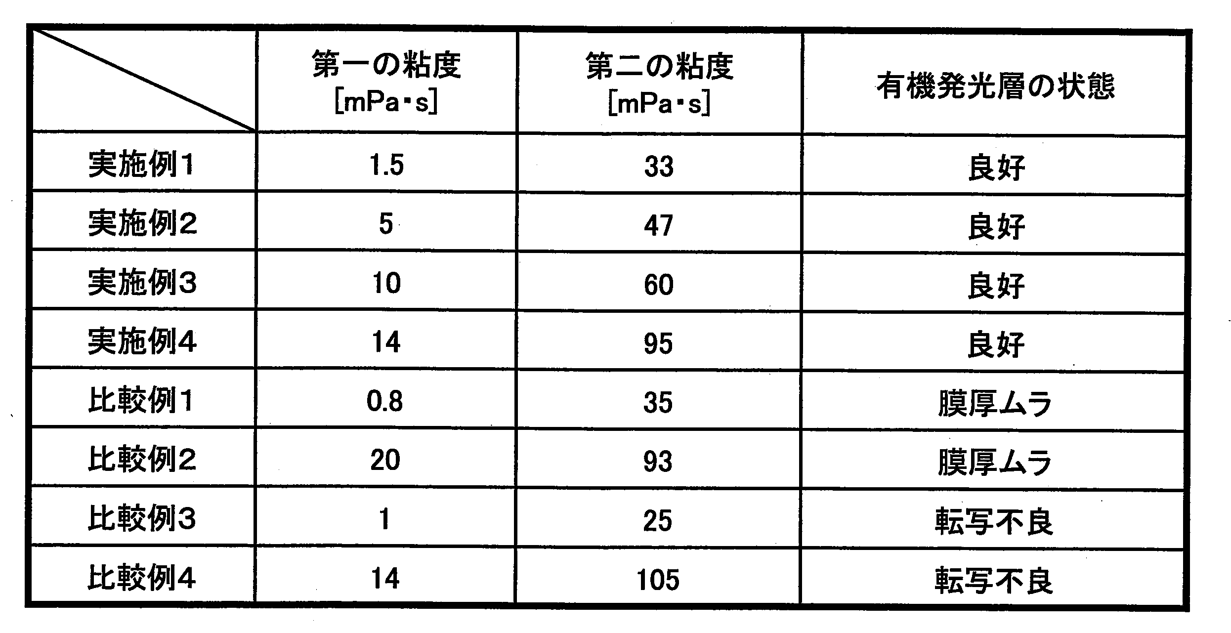
一方、比較例1では第一の粘度が低すぎるため、アニロックスロール上でインクが移動して不均一なインク膜厚となり、印刷工程後の有機発光層には膜厚ムラが生じていた。
また、比較例2では、第一の粘度が高すぎるため、アニロックスロール上で均一にレベリングされず、印刷工程後の有機発光層には膜厚ムラが生じていた。
また、比較例3では、第二の粘度が低すぎるため、凸版の凹部にインクが流れ込み、凸版から転写されない転写不良が生じた。
また、比較例4では、第二の粘度が高すぎるため、転移の際にアニロックスロール上にインクが残留し、凸版から転写されない転写不良が生じた。
さらに比較例5として、図13に示す構成に凸版を洗浄する版洗浄ユニット125を加えた凸版印刷装置を用いた。すなわち、凸版4と、版下クッション3を介して凸版4が装着される回転式の版胴5と、凸版4の版面にインクを供給するためのアニロックスロール1と、アニロックスロール1にインクを供給するインクチャンバー8と、アニロックスロール上の余分なインクを掻き落とすドクターブレード2と、被印刷基板7が載置される基板定盤6と、を有して構成された凸版印刷装置である。
作製したそれぞれの有機エレクトロルミネッセンス素子に電流を印加して発光させたところ、実施例1では全ての基板で均一に発光したが、比較例では複数の基板でダークスポットが生じていた。さらに有機発光層を形成した後、封止する前の段階で、発光層に混入した異物の量を検査した。検査は、CCDカメラを用いて異物サイズが2μmまで検出可能な検査装置を用いて行なった。検査は、ワンフレーム12画素×9画素でスキャンを行い実施例1及び比較例における異物量を算出した。
102:塗工装置
103:版下クッション
104:凸版
105:版胴
106:基板定盤
107:被印刷基板
108:定量ポンプ
109:インクタンク
110:インク回収ユニット
111:回収タンク
112:アニロックスロール洗浄ユニット
113:乾燥機構
114:アニロックス洗浄機構
115:送風ユニット
115a:気体噴射ノズル
115b:加圧気体供給ホース
116:洗浄液供給ユニット
116a:洗浄液供給ノズル
116b:洗浄液供給ホース
117:洗浄液回収ユニット
118:吸引ユニット
118a:吸引口
118b:吸引ホース
119:受け皿
120:洗浄機構カバー
121:共通ノズル
125:版洗浄ユニット
130:アニロックスロール移動機構
220A:インク塗膜(塗工装置による塗工の直後)
220B:インク塗膜(凸版へのインク転移直前)
501:基板
502:画素電極
503:絶縁層
504:正孔輸送層
505(505R,505G,505B):有機発光層(赤、緑、青)
506:対向電極
507:ガラスキャップ
508:接着材
701:アニロックスロール
701A:アニロックスロール表面
702:ドクターブレード
703:版下クッション
704:凸版
705:版胴
706:基板定盤
707:被印刷基板
708:インクチャンバー
710:ベタロール
711:インク塗膜
Claims (14)
- 回転式の版胴と、
版胴上に配置した凸版と、
表面に凹凸加工が施され、凸版にインクを供給するアニロックスロールと、
アニロックスロール表面にインクを塗布してインク塗膜を形成する塗工装置と、
を備えることを特徴とする凸版印刷装置。 - アニロックスロール上の前記インク塗膜に含まれる溶媒の揮発を促進させてインクの乾燥状態を制御する乾燥制御手段を備えることを特徴とする請求項1に記載の凸版印刷装置。
- 前記凸版印刷装置は制御手段を備え、
制御手段は、少なくとも塗工装置のインク塗布量と、インクの乾燥状態を制御することを特徴とする請求項2に記載の凸版印刷装置。 - 凸版とアニロックスロールを離間させる移動機構を備え、
前記乾燥制御手段は、凸版とアニロックスロールを離間させた状態で動作する乾燥機構であることを特徴とする請求項2又は3に記載の凸版印刷装置。 - 前記乾燥手段は、前記インク塗膜の領域に気流を生じさせて揮発を促進させる機構であることを特徴とする請求項2乃至4のいずれかに記載の凸版印刷装置。
- 前記乾燥手段は、前記インク塗膜の領域を低圧にして揮発を促進させる機構であることを特徴とする請求項2乃至4のいずれかに記載の凸版印刷装置。
- 前記乾燥手段は、遠赤外線照射装置によりインク塗膜を加熱することを特徴とする請求項2乃至4のいずれかに記載の凸版印刷装置。
- アニロックスロールを洗浄するアニロックス洗浄機構を備えたこと特徴する請求項1乃至4のいずれかに記載の凸版印刷装置。
- 前記アニロックス洗浄機構は、アニロックスにロールに洗浄液を吐出する洗浄液供給手段と、洗浄液を除去する洗浄液除去手段と、洗浄液に溶解したインク及び洗浄液を回収するインク回収ユニットとを備えることを特徴とする請求項8に記載の凸版印刷装置。
- 凸版を洗浄する版洗浄機構を備えたこと特徴する請求項1乃至4のいずれかに記載の凸版印刷装置。
- 請求項1乃至10のいずれかに記載の凸版印刷装置を用いて製造したことを特徴とする印刷物の製造方法。
- 表面に凹凸加工が施されたアニロックスロールから凸版上にインクを供給し、凸版からインクを被印刷基板上に転写する印刷物の製造方法であって、
アニロックスロール表面の凹部にインクを充填し、凸部を覆うようにインクを塗布する工程と、
アニロックスロール上でインク濃度を上げる揮発工程と、
次にアニロックスロールから凸版上にインクを転移させる工程と、
インクを凸版から被印刷基板に転写する工程と、
を有する印刷物の製造方法。 - 前記アニロックスロール表面にインクを塗布する工程におけるインクの粘度が1mPa・s以上15mPa・s以下であり、被印刷基板に転写する工程でのインクの粘度が30mPa・s以上100mPa・s以下であることを特徴とする請求項1に記載の印刷物の製造方法。
- 基板上に、陰極及び陽極と、陰極と陽極との間に少なくとも有機発光層を含む有機発光媒体層が挟持された有機エレクトロルミネッセンス素子の製造方法であって、
前記インクが有機発光材料を溶解した有機発光インクであり、
前記有機発光層を請求項11乃至13のいずれかに記載の印刷物の製造方法を用いて形成したことを特徴とする有機エレクトロルミネッセンス素子の製造方法。
Priority Applications (4)
| Application Number | Priority Date | Filing Date | Title |
|---|---|---|---|
| CN201180017187.0A CN102858541B (zh) | 2010-03-31 | 2011-03-01 | 凸版印刷装置,使用其的印刷物和有机电致发光元件制造方法 |
| JP2012508156A JPWO2011122204A1 (ja) | 2010-03-31 | 2011-03-01 | 凸版印刷装置並びにそれを用いた印刷物及び有機エレクトロルミネッセンス素子の製造方法 |
| KR1020127025675A KR20130038822A (ko) | 2010-03-31 | 2011-03-01 | 볼록판 인쇄 장치 및 그것을 사용한 인쇄물 및 유기 일렉트로 루미네센스 소자의 제조 방법 |
| US13/627,882 US20130019768A1 (en) | 2010-03-31 | 2012-09-26 | Relief Printing Apparatus, Printed Matter Using the Same, and Method of Manufacturing Organic Electroluminescent Element |
Applications Claiming Priority (2)
| Application Number | Priority Date | Filing Date | Title |
|---|---|---|---|
| JP2010-082323 | 2010-03-31 | ||
| JP2010082323 | 2010-03-31 |
Related Child Applications (1)
| Application Number | Title | Priority Date | Filing Date |
|---|---|---|---|
| US13/627,882 Continuation US20130019768A1 (en) | 2010-03-31 | 2012-09-26 | Relief Printing Apparatus, Printed Matter Using the Same, and Method of Manufacturing Organic Electroluminescent Element |
Publications (1)
| Publication Number | Publication Date |
|---|---|
| WO2011122204A1 true WO2011122204A1 (ja) | 2011-10-06 |
Family
ID=44711933
Family Applications (1)
| Application Number | Title | Priority Date | Filing Date |
|---|---|---|---|
| PCT/JP2011/054638 Ceased WO2011122204A1 (ja) | 2010-03-31 | 2011-03-01 | 凸版印刷装置並びにそれを用いた印刷物及び有機エレクトロルミネッセンス素子の製造方法 |
Country Status (6)
| Country | Link |
|---|---|
| US (1) | US20130019768A1 (ja) |
| JP (1) | JPWO2011122204A1 (ja) |
| KR (1) | KR20130038822A (ja) |
| CN (1) | CN102858541B (ja) |
| TW (1) | TWI526322B (ja) |
| WO (1) | WO2011122204A1 (ja) |
Cited By (7)
| Publication number | Priority date | Publication date | Assignee | Title |
|---|---|---|---|---|
| JP5220219B1 (ja) * | 2012-08-24 | 2013-06-26 | ミクロンメタル株式会社 | 有機材料の除去方法 |
| KR20130136886A (ko) * | 2012-06-05 | 2013-12-13 | 엘지디스플레이 주식회사 | 배향막 인쇄장치 |
| JP2014154278A (ja) * | 2013-02-06 | 2014-08-25 | Toppan Printing Co Ltd | 凸版印刷装置及び有機el素子形成方法 |
| JP2015058601A (ja) * | 2013-09-18 | 2015-03-30 | 凸版印刷株式会社 | 凸版印刷装置 |
| JP2019142217A (ja) * | 2018-02-19 | 2019-08-29 | ゼロックス コーポレイションXerox Corporation | パターンフリーアニロックスインク付けシステムおよび方法 |
| CN111495802A (zh) * | 2020-04-22 | 2020-08-07 | 河南中烟工业有限责任公司 | 手动推压式除尘装置 |
| JP7041980B1 (ja) * | 2020-11-27 | 2022-03-25 | 全利機械股▲分▼有限公司 | 印刷ローラのローラ表面を洗浄する結合機構 |
Families Citing this family (13)
| Publication number | Priority date | Publication date | Assignee | Title |
|---|---|---|---|---|
| JP5943867B2 (ja) * | 2013-03-26 | 2016-07-05 | 富士フイルム株式会社 | 印刷装置及び印刷方法 |
| US9751260B2 (en) | 2013-07-24 | 2017-09-05 | The Boeing Company | Additive-manufacturing systems, apparatuses and methods |
| KR101719570B1 (ko) * | 2014-04-22 | 2017-03-24 | 한국기계연구원 | 블랭킷의 팽윤 제어시스템 |
| TWI661947B (zh) * | 2017-11-17 | 2019-06-11 | 財團法人工業技術研究院 | 凹版轉印機台 |
| CN107953659A (zh) * | 2017-11-28 | 2018-04-24 | 北京印刷学院 | 一种凸版印版的制造方法及其生产设备 |
| CN108189546B (zh) * | 2017-12-29 | 2024-03-29 | 海宁市伯恩特日用品有限公司 | 一种用于真空压缩袋的印花装置 |
| JP7051446B2 (ja) * | 2018-01-10 | 2022-04-11 | 株式会社ジャパンディスプレイ | 表示装置の製造方法 |
| CN108909165A (zh) * | 2018-08-28 | 2018-11-30 | 浙江佳燕日用品有限公司 | 印管机 |
| CN109435432B (zh) * | 2018-12-14 | 2020-09-18 | 浙江方邦机械有限公司 | 一种利用凹凸版配合去除多余油墨的凸版印刷机 |
| US11969992B2 (en) | 2019-09-20 | 2024-04-30 | Hempel A/S | Printer for applying a conductive pattern to a surface |
| CN112874128B (zh) * | 2021-01-15 | 2022-07-15 | 深圳市旺盈彩盒纸品有限公司 | 一种纸板印刷装置及其印刷方法 |
| CN113430739A (zh) * | 2021-06-21 | 2021-09-24 | 厦门延江新材料股份有限公司 | 一种局部涂布装置及其涂布方法 |
| CN118390627B (zh) * | 2024-06-27 | 2024-08-30 | 山西农业大学 | 一种用于市政工程的环保型排水系统 |
Citations (7)
| Publication number | Priority date | Publication date | Assignee | Title |
|---|---|---|---|---|
| JPS54154606A (en) * | 1978-05-24 | 1979-12-05 | Mitsubishi Heavy Ind Ltd | Flexo printer |
| JPH0592554A (ja) * | 1991-09-30 | 1993-04-16 | Isowa Ind Co | 段ボールシートへの印刷方法および装置 |
| JPH08295006A (ja) * | 1995-04-26 | 1996-11-12 | Sharp Corp | 薄膜印刷装置 |
| JPH08309961A (ja) * | 1995-05-24 | 1996-11-26 | Dainippon Printing Co Ltd | 印刷方法及び印刷装置 |
| JP2003291307A (ja) * | 2002-04-04 | 2003-10-14 | Toyota Motor Corp | 印刷装置および印刷方法 |
| JP2008296547A (ja) * | 2007-06-04 | 2008-12-11 | Toppan Printing Co Ltd | 凸版印刷装置 |
| JP2009272143A (ja) * | 2008-05-07 | 2009-11-19 | Dainippon Screen Mfg Co Ltd | 塗布装置 |
Family Cites Families (6)
| Publication number | Priority date | Publication date | Assignee | Title |
|---|---|---|---|---|
| DE3101243C2 (de) * | 1981-01-16 | 1983-10-13 | Niedermayr Papierwarenfabrik Ag, 8200 Rosenheim | Rotatives Flexo- bzw. indirektes Tiefdruckverfahren, sowie Vorrichtung zur Durchführung des Verfahrens |
| CN2181393Y (zh) * | 1993-12-11 | 1994-11-02 | 上海紫明机械有限公司 | 热涂碳印刷机 |
| DE10246271A1 (de) * | 2002-10-02 | 2004-04-15 | Windmöller & Hölscher Kg | Verfahren und Vorrichtung zum Einstellen der Farbdichte auf einem Bedruckstoff |
| JP4505242B2 (ja) * | 2004-03-17 | 2010-07-21 | 富士フイルム株式会社 | 平版印刷方法 |
| US7546803B2 (en) * | 2006-01-30 | 2009-06-16 | Toppan Printing Co., Ltd. | Letterpress printing machine |
| JP2008126506A (ja) * | 2006-11-20 | 2008-06-05 | Mitsubishi Heavy Ind Ltd | 印刷機の洗浄装置及び印刷機 |
-
2011
- 2011-03-01 WO PCT/JP2011/054638 patent/WO2011122204A1/ja not_active Ceased
- 2011-03-01 KR KR1020127025675A patent/KR20130038822A/ko not_active Ceased
- 2011-03-01 CN CN201180017187.0A patent/CN102858541B/zh not_active Expired - Fee Related
- 2011-03-01 JP JP2012508156A patent/JPWO2011122204A1/ja active Pending
- 2011-03-30 TW TW100110949A patent/TWI526322B/zh not_active IP Right Cessation
-
2012
- 2012-09-26 US US13/627,882 patent/US20130019768A1/en not_active Abandoned
Patent Citations (7)
| Publication number | Priority date | Publication date | Assignee | Title |
|---|---|---|---|---|
| JPS54154606A (en) * | 1978-05-24 | 1979-12-05 | Mitsubishi Heavy Ind Ltd | Flexo printer |
| JPH0592554A (ja) * | 1991-09-30 | 1993-04-16 | Isowa Ind Co | 段ボールシートへの印刷方法および装置 |
| JPH08295006A (ja) * | 1995-04-26 | 1996-11-12 | Sharp Corp | 薄膜印刷装置 |
| JPH08309961A (ja) * | 1995-05-24 | 1996-11-26 | Dainippon Printing Co Ltd | 印刷方法及び印刷装置 |
| JP2003291307A (ja) * | 2002-04-04 | 2003-10-14 | Toyota Motor Corp | 印刷装置および印刷方法 |
| JP2008296547A (ja) * | 2007-06-04 | 2008-12-11 | Toppan Printing Co Ltd | 凸版印刷装置 |
| JP2009272143A (ja) * | 2008-05-07 | 2009-11-19 | Dainippon Screen Mfg Co Ltd | 塗布装置 |
Cited By (10)
| Publication number | Priority date | Publication date | Assignee | Title |
|---|---|---|---|---|
| KR20130136886A (ko) * | 2012-06-05 | 2013-12-13 | 엘지디스플레이 주식회사 | 배향막 인쇄장치 |
| KR101971069B1 (ko) * | 2012-06-05 | 2019-04-22 | 엘지디스플레이 주식회사 | 배향막 인쇄장치 |
| JP5220219B1 (ja) * | 2012-08-24 | 2013-06-26 | ミクロンメタル株式会社 | 有機材料の除去方法 |
| JP2014154278A (ja) * | 2013-02-06 | 2014-08-25 | Toppan Printing Co Ltd | 凸版印刷装置及び有機el素子形成方法 |
| JP2015058601A (ja) * | 2013-09-18 | 2015-03-30 | 凸版印刷株式会社 | 凸版印刷装置 |
| JP2019142217A (ja) * | 2018-02-19 | 2019-08-29 | ゼロックス コーポレイションXerox Corporation | パターンフリーアニロックスインク付けシステムおよび方法 |
| JP7195957B2 (ja) | 2018-02-19 | 2022-12-26 | ゼロックス コーポレイション | パターンフリーアニロックスインク付けシステムおよび方法 |
| CN111495802A (zh) * | 2020-04-22 | 2020-08-07 | 河南中烟工业有限责任公司 | 手动推压式除尘装置 |
| JP7041980B1 (ja) * | 2020-11-27 | 2022-03-25 | 全利機械股▲分▼有限公司 | 印刷ローラのローラ表面を洗浄する結合機構 |
| CN114558812A (zh) * | 2020-11-27 | 2022-05-31 | 全利机械股份有限公司 | 复合式印刷滚轮表面清洁机构 |
Also Published As
| Publication number | Publication date |
|---|---|
| CN102858541B (zh) | 2015-11-25 |
| US20130019768A1 (en) | 2013-01-24 |
| TW201213146A (en) | 2012-04-01 |
| JPWO2011122204A1 (ja) | 2013-07-08 |
| TWI526322B (zh) | 2016-03-21 |
| CN102858541A (zh) | 2013-01-02 |
| KR20130038822A (ko) | 2013-04-18 |
Similar Documents
| Publication | Publication Date | Title |
|---|---|---|
| WO2011122204A1 (ja) | 凸版印刷装置並びにそれを用いた印刷物及び有機エレクトロルミネッセンス素子の製造方法 | |
| JP2006286309A (ja) | 有機el表示装置とその製造方法 | |
| US8040049B2 (en) | Organic EL element and method for manufacturing thereof | |
| JP5482382B2 (ja) | 凸版印刷装置、印刷物の製造方法、有機el素子の製造方法 | |
| JP5509646B2 (ja) | 凸版印刷装置 | |
| JP2014159089A (ja) | 印刷装置および印刷方法 | |
| US20070190236A1 (en) | Organic electroluminescent element and the manufacturing method | |
| JP5604935B2 (ja) | 凸版印刷装置及び有機elパネルの製造方法 | |
| JP2011113654A (ja) | 有機el素子及びその製造方法 | |
| JP5418115B2 (ja) | 凸版印刷機 | |
| JP5369802B2 (ja) | パターン形成用凸版及び有機el素子並びに電子回路 | |
| JP4961694B2 (ja) | 有機el素子の製造方法 | |
| JP4747637B2 (ja) | 有機elディスプレイパネルの製造方法 | |
| JP6127571B2 (ja) | 凸版印刷装置及び有機el素子の製造方法 | |
| JP6035807B2 (ja) | 凸版印刷装置 | |
| JP5050518B2 (ja) | 樹脂凸版の製造方法及び現像装置並びに印刷物の製造方法及び有機el素子の製造方法 | |
| JP2014157764A (ja) | 精密印刷方法及び精密印刷製造物 | |
| JP2014067543A (ja) | 有機el素子及び有機el素子の製造方法 | |
| JP5899752B2 (ja) | 凸版印刷装置及び有機elパネルの製造方法 | |
| JP2015157390A (ja) | 印刷装置 | |
| JP2008140579A (ja) | 有機el素子及びその製造方法、凸版 | |
| JP2006286241A (ja) | 有機elディスプレイパネルおよびその製造方法 | |
| JP2015185531A (ja) | 有機エレクトロルミネッセンス素子及びその製造方法 | |
| JP2013071337A (ja) | 印刷装置及び有機機能素子製造方法 | |
| JP2015030217A (ja) | 印刷装置 |
Legal Events
| Date | Code | Title | Description |
|---|---|---|---|
| WWE | Wipo information: entry into national phase |
Ref document number: 201180017187.0 Country of ref document: CN |
|
| 121 | Ep: the epo has been informed by wipo that ep was designated in this application |
Ref document number: 11762444 Country of ref document: EP Kind code of ref document: A1 |
|
| WWE | Wipo information: entry into national phase |
Ref document number: 2012508156 Country of ref document: JP |
|
| ENP | Entry into the national phase |
Ref document number: 20127025675 Country of ref document: KR Kind code of ref document: A |
|
| NENP | Non-entry into the national phase |
Ref country code: DE |
|
| 122 | Ep: pct application non-entry in european phase |
Ref document number: 11762444 Country of ref document: EP Kind code of ref document: A1 |