WO2011122202A1 - 成形体製造装置および成形体の製造方法 - Google Patents
成形体製造装置および成形体の製造方法 Download PDFInfo
- Publication number
- WO2011122202A1 WO2011122202A1 PCT/JP2011/054587 JP2011054587W WO2011122202A1 WO 2011122202 A1 WO2011122202 A1 WO 2011122202A1 JP 2011054587 W JP2011054587 W JP 2011054587W WO 2011122202 A1 WO2011122202 A1 WO 2011122202A1
- Authority
- WO
- WIPO (PCT)
- Prior art keywords
- molded body
- manufacturing apparatus
- flow path
- cavity
- resin composition
- Prior art date
- Legal status (The legal status is an assumption and is not a legal conclusion. Google has not performed a legal analysis and makes no representation as to the accuracy of the status listed.)
- Ceased
Links
Images


Classifications
-
- B—PERFORMING OPERATIONS; TRANSPORTING
- B29—WORKING OF PLASTICS; WORKING OF SUBSTANCES IN A PLASTIC STATE IN GENERAL
- B29C—SHAPING OR JOINING OF PLASTICS; SHAPING OF MATERIAL IN A PLASTIC STATE, NOT OTHERWISE PROVIDED FOR; AFTER-TREATMENT OF THE SHAPED PRODUCTS, e.g. REPAIRING
- B29C43/00—Compression moulding, i.e. applying external pressure to flow the moulding material; Apparatus therefor
- B29C43/02—Compression moulding, i.e. applying external pressure to flow the moulding material; Apparatus therefor of articles of definite length, i.e. discrete articles
- B29C43/04—Compression moulding, i.e. applying external pressure to flow the moulding material; Apparatus therefor of articles of definite length, i.e. discrete articles using movable moulds
- B29C43/06—Compression moulding, i.e. applying external pressure to flow the moulding material; Apparatus therefor of articles of definite length, i.e. discrete articles using movable moulds continuously movable in one direction, e.g. mounted on chains, belts
- B29C43/08—Compression moulding, i.e. applying external pressure to flow the moulding material; Apparatus therefor of articles of definite length, i.e. discrete articles using movable moulds continuously movable in one direction, e.g. mounted on chains, belts with circular movement, e.g. mounted on rolls, turntables
-
- B—PERFORMING OPERATIONS; TRANSPORTING
- B29—WORKING OF PLASTICS; WORKING OF SUBSTANCES IN A PLASTIC STATE IN GENERAL
- B29C—SHAPING OR JOINING OF PLASTICS; SHAPING OF MATERIAL IN A PLASTIC STATE, NOT OTHERWISE PROVIDED FOR; AFTER-TREATMENT OF THE SHAPED PRODUCTS, e.g. REPAIRING
- B29C43/00—Compression moulding, i.e. applying external pressure to flow the moulding material; Apparatus therefor
- B29C43/02—Compression moulding, i.e. applying external pressure to flow the moulding material; Apparatus therefor of articles of definite length, i.e. discrete articles
- B29C43/10—Isostatic pressing, i.e. using non-rigid pressure-exerting members against rigid parts or dies
-
- B—PERFORMING OPERATIONS; TRANSPORTING
- B29—WORKING OF PLASTICS; WORKING OF SUBSTANCES IN A PLASTIC STATE IN GENERAL
- B29C—SHAPING OR JOINING OF PLASTICS; SHAPING OF MATERIAL IN A PLASTIC STATE, NOT OTHERWISE PROVIDED FOR; AFTER-TREATMENT OF THE SHAPED PRODUCTS, e.g. REPAIRING
- B29C43/00—Compression moulding, i.e. applying external pressure to flow the moulding material; Apparatus therefor
- B29C43/02—Compression moulding, i.e. applying external pressure to flow the moulding material; Apparatus therefor of articles of definite length, i.e. discrete articles
- B29C43/18—Compression moulding, i.e. applying external pressure to flow the moulding material; Apparatus therefor of articles of definite length, i.e. discrete articles incorporating preformed parts or layers, e.g. compression moulding around inserts or for coating articles
-
- B—PERFORMING OPERATIONS; TRANSPORTING
- B29—WORKING OF PLASTICS; WORKING OF SUBSTANCES IN A PLASTIC STATE IN GENERAL
- B29C—SHAPING OR JOINING OF PLASTICS; SHAPING OF MATERIAL IN A PLASTIC STATE, NOT OTHERWISE PROVIDED FOR; AFTER-TREATMENT OF THE SHAPED PRODUCTS, e.g. REPAIRING
- B29C43/00—Compression moulding, i.e. applying external pressure to flow the moulding material; Apparatus therefor
- B29C43/32—Component parts, details or accessories; Auxiliary operations
- B29C43/36—Moulds for making articles of definite length, i.e. discrete articles
- B29C43/361—Moulds for making articles of definite length, i.e. discrete articles with pressing members independently movable of the parts for opening or closing the mould, e.g. movable pistons
-
- B—PERFORMING OPERATIONS; TRANSPORTING
- B30—PRESSES
- B30B—PRESSES IN GENERAL
- B30B11/00—Presses specially adapted for forming shaped articles from material in particulate or plastic state, e.g. briquetting presses, tabletting presses
- B30B11/02—Presses specially adapted for forming shaped articles from material in particulate or plastic state, e.g. briquetting presses, tabletting presses using a ram exerting pressure on the material in a moulding space
- B30B11/08—Presses specially adapted for forming shaped articles from material in particulate or plastic state, e.g. briquetting presses, tabletting presses using a ram exerting pressure on the material in a moulding space co-operating with moulds carried by a turntable
- B30B11/10—Presses specially adapted for forming shaped articles from material in particulate or plastic state, e.g. briquetting presses, tabletting presses using a ram exerting pressure on the material in a moulding space co-operating with moulds carried by a turntable intermittently rotated
-
- B—PERFORMING OPERATIONS; TRANSPORTING
- B30—PRESSES
- B30B—PRESSES IN GENERAL
- B30B15/00—Details of, or accessories for, presses; Auxiliary measures in connection with pressing
- B30B15/06—Platens or press rams
- B30B15/065—Press rams
-
- B—PERFORMING OPERATIONS; TRANSPORTING
- B30—PRESSES
- B30B—PRESSES IN GENERAL
- B30B15/00—Details of, or accessories for, presses; Auxiliary measures in connection with pressing
- B30B15/30—Feeding material to presses
- B30B15/302—Feeding material in particulate or plastic state to moulding presses
-
- H—ELECTRICITY
- H10—SEMICONDUCTOR DEVICES; ELECTRIC SOLID-STATE DEVICES NOT OTHERWISE PROVIDED FOR
- H10W—GENERIC PACKAGES, INTERCONNECTIONS, CONNECTORS OR OTHER CONSTRUCTIONAL DETAILS OF DEVICES COVERED BY CLASS H10
- H10W72/00—Interconnections or connectors in packages
- H10W72/50—Bond wires
-
- H—ELECTRICITY
- H10—SEMICONDUCTOR DEVICES; ELECTRIC SOLID-STATE DEVICES NOT OTHERWISE PROVIDED FOR
- H10W—GENERIC PACKAGES, INTERCONNECTIONS, CONNECTORS OR OTHER CONSTRUCTIONAL DETAILS OF DEVICES COVERED BY CLASS H10
- H10W74/00—Encapsulations, e.g. protective coatings
- H10W74/01—Manufacture or treatment
-
- H—ELECTRICITY
- H10—SEMICONDUCTOR DEVICES; ELECTRIC SOLID-STATE DEVICES NOT OTHERWISE PROVIDED FOR
- H10W—GENERIC PACKAGES, INTERCONNECTIONS, CONNECTORS OR OTHER CONSTRUCTIONAL DETAILS OF DEVICES COVERED BY CLASS H10
- H10W74/00—Encapsulations, e.g. protective coatings
- H10W74/10—Encapsulations, e.g. protective coatings characterised by their shape or disposition
- H10W74/111—Encapsulations, e.g. protective coatings characterised by their shape or disposition the semiconductor body being completely enclosed
-
- B—PERFORMING OPERATIONS; TRANSPORTING
- B29—WORKING OF PLASTICS; WORKING OF SUBSTANCES IN A PLASTIC STATE IN GENERAL
- B29C—SHAPING OR JOINING OF PLASTICS; SHAPING OF MATERIAL IN A PLASTIC STATE, NOT OTHERWISE PROVIDED FOR; AFTER-TREATMENT OF THE SHAPED PRODUCTS, e.g. REPAIRING
- B29C43/00—Compression moulding, i.e. applying external pressure to flow the moulding material; Apparatus therefor
- B29C43/02—Compression moulding, i.e. applying external pressure to flow the moulding material; Apparatus therefor of articles of definite length, i.e. discrete articles
- B29C43/10—Isostatic pressing, i.e. using non-rigid pressure-exerting members against rigid parts or dies
- B29C2043/106—Isostatic pressing, i.e. using non-rigid pressure-exerting members against rigid parts or dies using powder material
-
- B—PERFORMING OPERATIONS; TRANSPORTING
- B29—WORKING OF PLASTICS; WORKING OF SUBSTANCES IN A PLASTIC STATE IN GENERAL
- B29K—INDEXING SCHEME ASSOCIATED WITH SUBCLASSES B29B, B29C OR B29D, RELATING TO MOULDING MATERIALS OR TO MATERIALS FOR MOULDS, REINFORCEMENTS, FILLERS OR PREFORMED PARTS, e.g. INSERTS
- B29K2105/00—Condition, form or state of moulded material or of the material to be shaped
- B29K2105/25—Solid
- B29K2105/251—Particles, powder or granules
-
- H—ELECTRICITY
- H10—SEMICONDUCTOR DEVICES; ELECTRIC SOLID-STATE DEVICES NOT OTHERWISE PROVIDED FOR
- H10W—GENERIC PACKAGES, INTERCONNECTIONS, CONNECTORS OR OTHER CONSTRUCTIONAL DETAILS OF DEVICES COVERED BY CLASS H10
- H10W72/00—Interconnections or connectors in packages
- H10W72/50—Bond wires
- H10W72/531—Shapes of wire connectors
- H10W72/536—Shapes of wire connectors the connected ends being ball-shaped
-
- H—ELECTRICITY
- H10—SEMICONDUCTOR DEVICES; ELECTRIC SOLID-STATE DEVICES NOT OTHERWISE PROVIDED FOR
- H10W—GENERIC PACKAGES, INTERCONNECTIONS, CONNECTORS OR OTHER CONSTRUCTIONAL DETAILS OF DEVICES COVERED BY CLASS H10
- H10W72/00—Interconnections or connectors in packages
- H10W72/50—Bond wires
- H10W72/531—Shapes of wire connectors
- H10W72/5363—Shapes of wire connectors the connected ends being wedge-shaped
-
- H—ELECTRICITY
- H10—SEMICONDUCTOR DEVICES; ELECTRIC SOLID-STATE DEVICES NOT OTHERWISE PROVIDED FOR
- H10W—GENERIC PACKAGES, INTERCONNECTIONS, CONNECTORS OR OTHER CONSTRUCTIONAL DETAILS OF DEVICES COVERED BY CLASS H10
- H10W72/00—Interconnections or connectors in packages
- H10W72/851—Dispositions of multiple connectors or interconnections
- H10W72/874—On different surfaces
- H10W72/884—Die-attach connectors and bond wires
-
- H—ELECTRICITY
- H10—SEMICONDUCTOR DEVICES; ELECTRIC SOLID-STATE DEVICES NOT OTHERWISE PROVIDED FOR
- H10W—GENERIC PACKAGES, INTERCONNECTIONS, CONNECTORS OR OTHER CONSTRUCTIONAL DETAILS OF DEVICES COVERED BY CLASS H10
- H10W74/00—Encapsulations, e.g. protective coatings
-
- H—ELECTRICITY
- H10—SEMICONDUCTOR DEVICES; ELECTRIC SOLID-STATE DEVICES NOT OTHERWISE PROVIDED FOR
- H10W—GENERIC PACKAGES, INTERCONNECTIONS, CONNECTORS OR OTHER CONSTRUCTIONAL DETAILS OF DEVICES COVERED BY CLASS H10
- H10W90/00—Package configurations
- H10W90/701—Package configurations characterised by the relative positions of pads or connectors relative to package parts
- H10W90/731—Package configurations characterised by the relative positions of pads or connectors relative to package parts of die-attach connectors
- H10W90/734—Package configurations characterised by the relative positions of pads or connectors relative to package parts of die-attach connectors between a chip and a stacked insulating package substrate, interposer or RDL
-
- H—ELECTRICITY
- H10—SEMICONDUCTOR DEVICES; ELECTRIC SOLID-STATE DEVICES NOT OTHERWISE PROVIDED FOR
- H10W—GENERIC PACKAGES, INTERCONNECTIONS, CONNECTORS OR OTHER CONSTRUCTIONAL DETAILS OF DEVICES COVERED BY CLASS H10
- H10W90/00—Package configurations
- H10W90/701—Package configurations characterised by the relative positions of pads or connectors relative to package parts
- H10W90/731—Package configurations characterised by the relative positions of pads or connectors relative to package parts of die-attach connectors
- H10W90/736—Package configurations characterised by the relative positions of pads or connectors relative to package parts of die-attach connectors between a chip and a stacked lead frame, conducting package substrate or heat sink
-
- H—ELECTRICITY
- H10—SEMICONDUCTOR DEVICES; ELECTRIC SOLID-STATE DEVICES NOT OTHERWISE PROVIDED FOR
- H10W—GENERIC PACKAGES, INTERCONNECTIONS, CONNECTORS OR OTHER CONSTRUCTIONAL DETAILS OF DEVICES COVERED BY CLASS H10
- H10W90/00—Package configurations
- H10W90/701—Package configurations characterised by the relative positions of pads or connectors relative to package parts
- H10W90/751—Package configurations characterised by the relative positions of pads or connectors relative to package parts of bond wires
- H10W90/756—Package configurations characterised by the relative positions of pads or connectors relative to package parts of bond wires between a chip and a stacked lead frame, conducting package substrate or heat sink
Definitions
- the present invention relates to a molded body manufacturing apparatus and a molded body manufacturing method.
- a semiconductor package in which a semiconductor chip (semiconductor element) is covered (sealed) with a resin sealing material is known.
- the sealing material of the semiconductor package is formed by molding a resin molded body by, for example, transfer molding.
- the resin composition as the base material is compression-molded into a tablet shape (block shape) with a tableting machine (see, for example, Patent Document 1).
- the part touched by the resin composition is usually made of metal, and the part may be worn out to generate metal powder.
- the invention described in Patent Document 1 is configured such that when a powder such as the metal powder adheres to a molded body, the powder is blown off with air.
- the powder adhering to the molded body cannot be sufficiently blown away only by applying air. For this reason, the powder remains in the molded body. If the remaining powder is a metal powder, the compact is a mixture of the metal powder as a foreign substance. When this molded body is used for sealing a semiconductor package, the semiconductor chip cannot be reliably insulated and sealed, and a short circuit may occur in the semiconductor chip due to the mixed metal powder.
- An object of the present invention is to provide a molded body manufacturing apparatus and a molded body manufacturing method capable of reliably preventing the metal powder from being mixed into the molded body when the molded body is produced by compression molding the resin composition. It is to provide.
- a molded body manufacturing apparatus for manufacturing a molded body by compression molding a resin composition which is a molding material An apparatus main body having a plate shape to which the resin composition is supplied and at least one mold having a cavity opening in the vertical direction is mounted and rotatable about a vertical axis; When the resin composition is supplied into the cavity at a first position where the apparatus main body is rotated by a predetermined angle, a first flow path member forming a tubular shape that forms a flow path through which the supplied resin composition passes.
- An upper compression member having an upper punch surface that is inserted from above into the cavity at a second position where the apparatus main body is rotated by a predetermined angle from the first position, and compresses the resin composition in the cavity;
- a lower compression member having a lower punch surface that is inserted into the cavity from the lower side in the second position and compresses the resin composition in the cavity together with the upper punch surface;
- the molded body in which the resin composition is compression-molded is released, and the released molded body is discharged from the cavity.
- a second flow path member having a tubular shape constituting a flow path through which the discharged molded body passes, An upper surface of the apparatus main body, a wall surface defining the cavity, an inner peripheral surface of the first flow path member, an inner peripheral surface of the second flow path member, the upper punch surface, and the lower
- the punched surface is an apparatus for producing a molded body, wherein at least 80% or more of the total surface area is made of a non-metal.
- the non-metals constituting the upper surface of the apparatus main body, the wall surface, the upper punch surface, and the lower punch surface are the same.
- the molded object manufacturing apparatus as described.
- the nonmetals constituting the inner peripheral surface of the first flow path member and the inner peripheral surface of the second flow path member are the same or different from each other (1) to (5) ).
- the inner peripheral surface of the first flow path member and the inner peripheral surface of the second flow path member are each inclined at least partially downward (1) to (1) to (10)
- the molded object manufacturing apparatus in any one of.
- the wall surface defining the cavity, the upper punch surface, and the lower punch surface are each coated with a release agent in advance, respectively (1) to (11) Molded body manufacturing equipment.
- a molded body manufacturing apparatus Using a molded body manufacturing apparatus according to any one of (1) to (14), a molded body is manufactured by compression molding a resin composition that is a molding material. Production method.
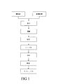
- FIG. 1 is a diagram illustrating a production process of a resin composition.
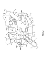
- FIG. 2 is a schematic perspective view of the molded body manufacturing apparatus of the present invention.
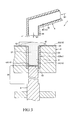
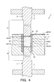
- 3 is a cross-sectional view taken along line AA in FIG. 4 is a cross-sectional view taken along line BB in FIG.
- FIG. 5 is a cross-sectional view taken along the line CC in FIG.
- FIG. 6 is a partial cross-sectional view of an IC package using a resin composition.
- FIG. 1 is a diagram showing a manufacturing process of a resin composition
- FIG. 2 is a schematic perspective view of a molded body manufacturing apparatus of the present invention
- FIG. 3 is a cross-sectional view taken along line AA in FIG. 2
- FIG. 2 is a cross-sectional view taken along line BB in FIG. 2
- FIG. 5 is a cross-sectional view taken along line CC in FIG. 2
- FIG. 6 is a partial cross-sectional view of an IC package using the resin composition.
- the upper side in FIGS. 2 to 6 is referred to as “upper” or “upper”, and the lower side is referred to as “lower” or “lower”.
- a molded body manufacturing apparatus (tablet pressing apparatus) 1 of the present invention shown in FIG. 2 is an apparatus used in a tableting process when manufacturing a molded body Q2 from a resin composition.
- the entire manufacturing process until the resin composition is manufactured from the raw materials will be described.
- each material which is a raw material of a resin composition is prepared.
- the raw material includes a resin, a curing agent, and a filler (fine particles), and further includes a curing accelerator and a coupling agent as necessary.
- a resin an epoxy resin is preferable.
- epoxy resin examples include a cresol novolac type, a biphenyl type, a dicyclopentadiene type, a triphenolmethane type, and a polyaromatic ring type.
- Examples of the curing agent include a phenol novolac type, a phenol aralkyl type, a triphenolmethane type, and a polyaromatic ring type.
- Examples of the filler include fused silica (crushed and spherical), crystalline silica, alumina, and the like.
- Examples of the curing accelerator include phosphorus compounds and amine compounds.
- Examples of the coupling agent include silane compounds.
- the predetermined material may be abbreviate
- examples of other materials include a colorant, a release agent, a low stress agent, and a flame retardant.
- Examples of the flame retardant include brominated epoxy resin, antimony oxide, and non-halo / non-antimony type.
- Examples of the non-halo / non-antimony flame retardant include organic phosphorus, metal hydrate, nitrogen-containing resin, and the like.
- a predetermined material among the raw materials is first pulverized (finely pulverized) by a pulverizing apparatus such as a continuous rotating ball mill so as to have a predetermined particle size distribution.
- the raw material to be crushed is, for example, a raw material other than a filler such as a resin, a curing agent, and an accelerator, but a part of the filler can be added.
- a predetermined material of the raw materials, for example, all or a part (remainder) of the filler can be subjected to a surface treatment.
- a surface treatment for example, a coupling agent or the like is attached to the surface of the filler.
- the fine pulverization and the surface treatment may be performed at the same time, or one of them may be performed first.
- mixing device Next, the respective materials are thoroughly mixed by a mixing device.
- a mixing apparatus for example, a high-speed mixer having rotating blades can be used.
- the mixed material is kneaded by a kneading apparatus.
- a kneading apparatus for example, an extrusion kneader such as a single-screw kneading extruder, a biaxial kneading extruder, or a roll kneader such as a mixing roll can be used.
- the kneaded material (resin composition) which is the kneaded material is degassed.
- This deaeration can be performed by, for example, a vacuum pump connected to a discharge port for discharging the kneaded material of the kneading apparatus.
- the degassed lump kneaded material is formed into a sheet shape with a forming apparatus to obtain a sheet-like material (sheet material).
- a forming apparatus for example, an apparatus that has a pair of rollers and presses the kneaded material between these rollers to form a sheet can be used.
- the sheet material is pulverized with a pulverizer so as to have a predetermined particle size distribution to obtain a powdery material (hereinafter referred to as “powder Q1”).
- a pulverizer for example, a hammer pulverizer, a knife pulverizer, a pin mill, or the like can be used.
- a die having a small diameter is installed at the outlet of the kneader and discharged from the die without going through the sheeting, cooling, and pulverization steps described above.
- a hot cut method of obtaining a granular resin composition by cutting the molten resin composition to a predetermined length with a cutter or the like can also be used. In this case, after obtaining the granular resin composition by the hot cut method, it is preferable to perform deaeration before the temperature of the resin composition is lowered so much.
- this molded body Q2 is used for covering (sealing) a semiconductor chip (IC chip) 901, for example, and becomes a mold part 902 constituting an exterior part of the semiconductor package (IC package) 900.
- the semiconductor chip 901 can be protected by the mold part 902.
- the resin composition is formed by, for example, transfer molding or the like and the semiconductor chip 901 is covered as a sealing material.
- a plurality of lead frames 903 protrude from the mold part 902, and each lead frame 903 is composed of a wire 904 made of a conductive metal material such as gold, for example. It is electrically connected to the semiconductor chip 901 via
- the molded body manufacturing apparatus 1 shown in FIG. 2 executes the molded body manufacturing method of the present invention, that is, when the molded body Q2 is manufactured by compression molding the powder Q1 (resin composition) as a molding material. It is a device used for.
- the molded body manufacturing apparatus 1 includes a device main body 2, a plurality of (eight in the configuration shown in FIG. 2) molds 3 attached to the apparatus main body 2, and a flow path through which the powder Q1 toward the mold 3 passes.
- the first flow path member 4 that constitutes, the upper compression member 5 that compresses the powder Q1 in the molding die 3, and the lower compression member 6 that compresses the powder Q1 in the molding die 3 together with the upper compression member 5.
- a second flow path member 7 constituting a flow path through which the compression molded body Q2 passes.
- the apparatus main body 2 has a disk shape as a whole.
- the apparatus main body 2 is installed in the molded body manufacturing apparatus 1 in such a posture that the central axis 21 is parallel to the vertical direction. And the apparatus main body 2 can rotate around the central axis 21 (vertical axis).
- the apparatus main body 2 has a gear and a motor, for example, and the rotation mechanism (not shown) which rotates the said apparatus main body 2 is connected.
- the apparatus main body 2 has mounting portions 22 to which the eight molds 3 are respectively mounted and fixed. These mounting portions 22 are arranged at equiangular intervals around the central axis 21 of the apparatus main body 2. Further, as shown in FIGS. 3 and 4, each mounting portion 22 is configured by a concave portion opened in the upper surface 23 of the apparatus main body 2.
- the shape of the recess is a shape corresponding to the outer shape of the mold 3, that is, a cylindrical shape in the illustrated configuration.
- the mold 3 is a member that has a cylindrical shape that opens in the vertical direction, and whose hollow portion becomes the cavity 31.
- the shape of the cavity 31 is cylindrical.
- the inner peripheral surface (wall surface) 32 that defines the cavity 31 of the mold 3 has a circular cross-sectional shape. Thereby, for example, when the release agent is applied to the inner peripheral surface 32, the application work can be easily performed, and the release agent can be reliably applied to the entire inner peripheral surface 32. By applying a release agent to the inner peripheral surface 32 in advance, the molded product Q2 can be easily released.
- the release agent is not particularly limited, and examples thereof include silicone release agents such as organopolysiloxane, fluorine release agents such as polytetrafluoroethylene, alcohol release agents such as polyvinyl alcohol, paraffin, Examples include higher fatty acids, higher fatty acid metal salts, ester waxes, polyolefin waxes, waxes such as polyethylene and polyethylene oxide, and the like can be used alone or in combination of two or more.
- the upper compression member 5 is a long cylindrical member that compresses the powder Q ⁇ b> 1 in the cavity 31 of the mold 3.
- the upper compression member 5 is supported so as to be movable in the vertical direction by a moving mechanism (not shown). As a result, the upper compression member 5 can be inserted into the cavity 31 from above, and conversely, it can be removed from the cavity 31.
- the moving mechanism for moving the upper compression member 5 is not particularly limited, and may be configured to have a hydraulic cylinder or the like, for example.
- the outer diameter of the insertion portion 51 inserted into the cavity 31 is slightly smaller than the inner diameter of the mold 3.
- the lower surface of the insertion portion 51 constitutes an upper punch surface (compression surface) 52 that compresses the powder Q1 from above (see FIG. 4).
- the upper punch surface 52 has a planar shape. Since the upper punch surface 52 has such a simple shape, for example, when a release agent is applied to the upper punch surface 52, the application work can be easily performed. The release agent can be reliably applied to the whole. By previously applying a release agent to the upper punch surface 52, the molded body Q2 can be easily released.
- the upper punch surface 52 does not necessarily have to be a flat surface although it depends on the shape of the molded body Q2.
- the lower compression member 6 is a long cylindrical member that compresses the powder Q ⁇ b> 1 in the cavity 31 of the mold 3 together with the upper compression member 5.
- the lower compression member 6 is supported so as to be movable in the vertical direction by a moving mechanism (not shown). Thereby, the lower side compression member 6 can be inserted into the cavity 31 from the lower side, and the insertion depth can be changed (refer FIG. 3, FIG. 4).
- the moving mechanism for moving the lower compression member 6 is not particularly limited, and may be configured to have, for example, a hydraulic cylinder.
- the outer diameter of the insertion portion 61 inserted into the cavity 31 is slightly smaller than the inner diameter of the mold 3.
- the upper surface of the insertion portion 61 constitutes a lower punch surface (compression surface) 62 that compresses the powder Q1 from the lower side (see FIG. 4).
- the lower punch surface 62 has a planar shape. Since the lower punch surface 62 has such a simple shape, for example, when a release agent is applied to the lower punch surface 62, the application work can be easily performed. The release agent can be reliably applied to the whole. By previously applying a release agent to the lower punch surface 62, the molded product Q2 can be easily released.
- the lower punch surface 62 does not necessarily have to be a flat surface although it depends on the shape of the molded body Q2.
- the first flow path member 4 is a member used when supplying the powder Q1 into the cavity 31 of the single mold 3.
- the first flow path member 4 is configured by a tubular body having a circular cross section, and the powder Q1 supplied into the cavity 31 can pass through the inner cavity portion thereof.
- the first flow path member 4 has an opening that opens downward, and the opening functions as a discharge port 41 that discharges the powder Q1.
- the powder Q ⁇ b> 1 is discharged from the discharge port 41 and supplied into the cavity 31 of the mold 3.
- the first flow path member 4 has an inclined portion 42 inclined in the middle in the longitudinal direction. In the inclined portion 42, a part of the inner peripheral surface 43 of the first flow path member 4 is inclined downward, and the powder Q1 can easily flow down. Thereby, the powder Q1 can be quickly supplied to the mold 3.
- the second flow path member 7 is installed at a position different from the first flow path member 4 in the circumferential direction of the apparatus main body 2.
- the second flow path member 7 is a member through which the molded body Q2 discharged from the cavity 31 of the mold 3 passes.
- the second flow path member 7 is formed of a tubular body having a semicircular cross-sectional shape.
- the entire second flow path member 7 (inner peripheral surface 71) is inclined downward. Thereby, the molded object Q2 can flow down easily, and is collect
- a storage tray (not shown) that stores a plurality of molded bodies Q2 is installed at the collection destination. Thereby, the obtained some molded object Q2 can be conveyed collectively.
- first position When the apparatus main body 2 rotates counterclockwise by a predetermined angle from the initial state, at this position (hereinafter referred to as “first position”), the molding die 3 a1 is directly below the discharge port 41 of the first flow path member 4. Located (see FIGS. 2 and 3). In the first position, the powder Q1 is supplied and filled from the first flow path member 4 to the molding die 3a1 . This supply is such that the powder Q1 overflows from the cavity 31 of the mold 3a1 (see FIG. 3), and the excess portion Q1 ′ that overflows is removed before the powder Q1 is compression molded. As a result, the powder Q1 is filled in a certain amount without being excessive or insufficient. The excess portion Q1 ′ can be removed using, for example, a scraper.
- the molding die 3 a1 is retracted from the first flow path member 4.
- the mold 3 a1 moved from the first position will be referred to as “mold 3 a2 ”.
- the mold 3 a 2 is disposed directly below the upper compression member 5.
- the upper compression member 5 is lowered and the lower compression member 6 is raised, the upper punch surface 52 of the upper compression member 5 and the lower punch surface 62 of the lower compression member 6 are In the meantime, the powder Q1 in the cavity 31 is compressed. This compressed state is maintained until the apparatus main body 2 is in a third position described later. During this time, the powder Q1 is compression-molded and hardened to form a molded body Q2.
- the apparatus main body 2 rotates a predetermined angle (135 ° in FIG. 2) counterclockwise from the second position.
- the mold 3 a2 moved from the second position will be referred to as “mold 3 a3 ”.
- the mold 3 a3 when the upper compression member 5 rises at this rotated position (hereinafter referred to as “third position”) and the lower compression member 6 further rises with a movement amount smaller than the movement amount, the mold 3 a3.
- the molded body Q2 is released from the mold.
- the molded body Q2 faces the second flow path member 7 while being released from the mold, passes through the second flow path member 7, and is discharged out of the molded body manufacturing apparatus 1 (see FIG. 5). ).
- the movement of the molded body Q2 to the flow path member 7 can be performed using, for example, a scraper.
- the following parts are each comprised with the nonmetal.
- the upper surface 23 of the apparatus body 2 -Inner peripheral surface 32 of the mold 3 -Upper punch surface 52 of the upper compression member 5 -Lower punch surface 62 of the lower compression member 6 -Inner peripheral surface 43 of the first flow path member 4 -Inner peripheral surface 71 of the second flow path member 7
- the non-metal occupies at least 80% or more of the total surface area of each surface, and preferably occupies 100%.
- non-metallization is such that the surface of the scraper exemplified above is also non-metallized in addition to the above surfaces.
- the inner peripheral surface 43 of the flow path member 4 and the inner peripheral surface 71 of the second flow path member 7 are respectively parts where the powder Q1 or the molded body Q2 comes into contact (hereinafter these parts are collectively referred to as “contact part 10”. ”)".
- the contact portion 10 is made of a non-metal, the powder Q1 and the molded body Q2 are in contact with the contact portion 10 in the process of manufacturing the molded body Q2 from the powder Q1, and between them, Even if friction occurs and the contact portion 10 is worn away and part thereof is scraped off, the scraped part is naturally non-metallic.
- the contact portion 10 is made of metal, for example, when the formed body Q2 is manufactured, a metal powder is generated from the contact portion 10 due to wear as described above, and the metal powder is mixed therein. It becomes the body Q2.
- the molded body manufacturing apparatus 1 can reliably prevent such metal powder from being mixed into the molded body Q2 (1.0 wtppm or less, preferably 0.1 wtppm or less in terms of metal increase rate). Further, even if the scraped non-metal is mixed into the molded body Q2, the molded body Q2 can sufficiently withstand use for the mold portion 902 of the semiconductor package 900.
- nonmetal examples include ceramics or resin materials, and ceramics are particularly preferable.
- the ceramic is not particularly limited.
- oxide ceramics such as alumina, silica, titania, zirconia, yttria, calcium phosphate, nitride ceramics such as silicon nitride, aluminum nitride, titanium nitride, boron nitride, tungsten carbide, etc.
- the Vickers hardness Hv (specified in JIS Z 2244) of the ceramics (nonmetal) measured with a load of 500 gf as the oxidation ceramics constituting the contact portion 10 is not particularly limited and is, for example, 1300 or more. Preferably, it is 1500-1700. Thereby, it becomes the contact part 10 which was more excellent in abrasion resistance.
- the oxide ceramics having the Vickers hardness Hv in the above numerical range include zirconia and high-purity alumina.
- the part which wants to comprise can be coated with ceramics, and the coating film 24 can be formed (refer FIG. 3, FIG. 4).
- the coating film 33 can be formed on the portion to be formed (see FIGS. 3 and 4).
- the coating film 53 can be formed on the portion to be constituted (see FIG. 4).
- the lower compression member 6 is configured by the lower punch surface 62, a coating film 63 can be formed on the portion to be configured (see FIGS. 3 and 4).
- a coating film 44 can be formed on the portion to be configured (see FIG. 3).
- a coating film 72 can be formed on the portion to be configured (see FIG. 5).
- parts other than the part in which the coating film of each member is formed can be comprised with a metal material, for example.
- the apparatus main body 2, the mold 3, the upper compression member 5, the lower compression member 6, the first flow path member 4, and the second flow path member 7, The whole can also be comprised with nonmetals, such as ceramics.
- the contact portion 10 is easily and reliably made of ceramics.
- the thicknesses of the coating films 24, 33, 53, 63, 44 and 72 are not particularly limited, but are preferably 0.2 to 1 mm, for example, and 0.3 to 0.5 mm. Is more preferable. Moreover, the thickness of each film
- the ceramics (nonmetal) constituting the coating film 63 (lower punch surface 62) 6 are preferably the same, for example, zirconia. Since zirconia is superior in fracture toughness among ceramics, it is possible to prevent damage to the coating film by using zirconia in the rotating and / or sliding parts such as the above-mentioned surfaces. There is.
- the coating film 33 of the mold 3, the coating film 53 of the upper compression member 5, and the coating film 63 of the lower compression member 6 are made of ceramics, minute irregularities are formed on each surface. May be.
- the release agent is held by these minute irregularities, and the amount of application per release agent application can be made relatively small.
- the release agent during use of the molded body manufacturing apparatus 1 The number of times of application can be relatively small.
- the non-metals constituting the coating film 44 (inner peripheral surface 43) of the first flow path member 4 and the coating film 72 (inner peripheral surface 71) of the second flow path member 7 are the same or different.
- the coating film 44 and the coating film 72 can both be made of zirconia from the viewpoint of increasing the strength and the margin of wear.
- a film material corresponding to the load in contact with the film can be selected.
- the coating film 44 is made of zirconia and the coating film 72 is made of nylon. be able to.
- a material can also be appropriately selected according to specifications.
- the constituent materials are different from each other, there is an advantage that the workability can be facilitated by adhesion of powder, reduction of clogging, or weight reduction of equipment.
- each part which comprises a molded object manufacturing apparatus can be replaced with any structure capable of performing the same function.
- arbitrary components may be added.
- the number of molding dies installed in the apparatus main body is eight in the illustrated configuration, but is not limited to this, for example, one, two, three There may be four, five, six, seven or nine or more.
- the upper punch surface of the upper compression member and the lower punch surface of the lower compression member are each configured by a plane in the illustrated configuration, but are not limited thereto.
- the curved concave surface may be used.
- both the upper punch surface and the lower punch surface may be configured by a curved concave surface, or one may be configured by a flat surface and the other may be configured by a curved concave surface.
- the upper compression member, the lower compression member, and the size of the mold may be changeable (detachable).
- the first flow path member is configured by a tubular body having a circular cross section in the illustrated configuration, but is not limited thereto.
- the cross-sectional shape may be comprised with the tubular body which makes a semicircle.
- the second flow path member is configured by a tubular body having a semicircular cross-sectional shape in the illustrated configuration, but is not limited to this.
- the cross-sectional shape may be a tubular body having a circular shape.
- the portion with which the resin composition or the molded body comes into contact (hereinafter, this portion is referred to as “contact portion”) is reliably composed of a non-metal.
- the resin composition is compression-molded to produce a molded body
- the resin composition or the molded body comes into contact with the contact portion, friction is generated between them, and the contact portion is worn away and a part thereof is scraped off. Even so, the shaved material is naturally non-metallic.
- the contact portion is made of metal
- the molded body is manufactured, metal powder is generated from the contact portion due to wear as described above, and the molded body is mixed with the metal powder. End up.
- the present invention has industrial applicability.
Landscapes
- Engineering & Computer Science (AREA)
- Mechanical Engineering (AREA)
- Casting Or Compression Moulding Of Plastics Or The Like (AREA)
- Moulds For Moulding Plastics Or The Like (AREA)
- Processing And Handling Of Plastics And Other Materials For Molding In General (AREA)
- Powder Metallurgy (AREA)
Abstract
Description
(1) 成形材料である樹脂組成物を圧縮成形することにより成形体を製造する成形体製造装置であって、
前記樹脂組成物が供給され、上下方向に開口するキャビティを有する成形型が少なくとも1つ装着され、鉛直軸回りに回転可能な板状をなす装置本体と、
前記装置本体が所定角度回転した第1の位置で前記キャビティ内に前記樹脂組成物を供給する際、その供給される樹脂組成物が通過する流路を構成する管状をなす第1の流路部材と、
前記装置本体が前記第1の位置から所定角度回転した第2の位置で前記キャビティ内にその上側から挿入され、該キャビティ内の前記樹脂組成物を圧縮する上パンチ面を有する上側圧縮部材と、
前記第2の位置で前記キャビティ内にその下側から挿入され、該キャビティ内の前記樹脂組成物を前記上パンチ面とともに圧縮する下パンチ面を有する下側圧縮部材と、
前記装置本体が前記第2の位置から所定角度回転した第3の位置で、前記樹脂組成物が圧縮成形された前記成形体を離型し、該離型した成形体が前記キャビティ内から排出された際、その排出された成形体が通過する流路を構成する管状をなす第2の流路部材とを備え、
前記装置本体の上面と、前記キャビティを画成する壁面と、前記第1の流路部材の内周面と、前記第2の流路部材の内周面と、前記上パンチ面と、前記下パンチ面とは、その総表面積の少なくとも80%以上が非金属で構成されていることを特徴とする成形体製造装置。
まず、樹脂組成物の原材料である各材料を用意する。
カップリング剤としては、例えば、シラン化合物等が挙げられる。
図1に示すように、原材料のうちの所定の材料については、まず、連続式回転ボールミル等の粉砕装置により、所定の粒度分布となるように粉砕(微粉砕)する。この粉砕する原材料としては、例えば、樹脂、硬化剤、促進剤等の充填材以外の原材料であるが、充填材の一部を加えることもできる。
原材料のうちの所定の材料、例えば、充填材の全部または一部(残部)については、表面処理を施すことができる。この表面処理としては、例えば、充填材の表面にカップリング剤等を付着させる。なお、前記微粉砕と表面処理とは、同時に行ってもよく、また、いずれか一方を先に行ってもよい。
次に、混合装置により、前記各材料を完全に混合する。この混合装置としては、例えば、回転羽根を有する高速混合機等を用いることができる。
次に、混練装置により、前記混合された材料を混練する。この混練装置としては、例えば、1軸型混練押出機、2軸型混練押出機等の押出混練機やミキシングロール等のロール式混練機を用いることができる。
次に、前記混練された材料である混練物(樹脂組成物)に対し脱気を行う。この脱気は、例えば混練装置の前記混練された材料を排出する排出口に接続された真空ポンプによって行うことができる。
次に、前記脱気された塊状の混練物を、成形装置でシート状に成形し、シート状の材料(シート材)を得る。この成形装置としては、例えば、一対のローラを有し、これらのローラ間で混練物を加圧してシート状に成形する装置を用いることができる。
次に、冷却装置により、前記シート状の材料を冷却する。これにより、材料の粉砕を容易かつ確実に行うことができる。
次に、粉砕装置により、前記シート材を所定の粒度分布となるように粉砕し、粉末状の材料(以下「粉体Q1」と言う)を得る。この粉砕装置としては、例えば、ハンマー式粉砕機、ナイフ式粉砕機、ピンミル等を用いることができる。
次に、成形体製造装置1を用いることにより、多量の粉体Q1を圧縮成形して成形体Q2を容易かつ確実に得る。
図2に示す成形体製造装置1は、本発明の成形体の製造方法を実行する、すなわち、成形材料である粉体Q1(樹脂組成物)を圧縮成形することにより成形体Q2を製造する際に用いられる装置である。
・装置本体2の上面23
・成形型3の内周面32
・上側圧縮部材5の上パンチ面52
・下側圧縮部材6の下パンチ面62
・第1の流路部材4の内周面43
・第2の流路部材7の内周面71
Claims (15)
- 成形材料である樹脂組成物を圧縮成形することにより成形体を製造する成形体製造装置であって、
前記樹脂組成物が供給され、上下方向に開口するキャビティを有する成形型が少なくとも1つ装着され、鉛直軸回りに回転可能な板状をなす装置本体と、
前記装置本体が所定角度回転した第1の位置で前記キャビティ内に前記樹脂組成物を供給する際、その供給される樹脂組成物が通過する流路を構成する管状をなす第1の流路部材と、
前記装置本体が前記第1の位置から所定角度回転した第2の位置で前記キャビティ内にその上側から挿入され、該キャビティ内の前記樹脂組成物を圧縮する上パンチ面を有する上側圧縮部材と、
前記第2の位置で前記キャビティ内にその下側から挿入され、該キャビティ内の前記樹脂組成物を前記上パンチ面とともに圧縮する下パンチ面を有する下側圧縮部材と、
前記装置本体が前記第2の位置から所定角度回転した第3の位置で、前記樹脂組成物が圧縮成形された前記成形体を離型し、該離型した成形体が前記キャビティ内から排出された際、その排出された成形体が通過する流路を構成する管状をなす第2の流路部材とを備え、
前記装置本体の上面と、前記キャビティを画成する壁面と、前記第1の流路部材の内周面と、前記第2の流路部材の内周面と、前記上パンチ面と、前記下パンチ面とは、その総表面積の少なくとも80%以上が非金属で構成されていることを特徴とする成形体製造装置。 - 前記非金属は、セラミックスまたは樹脂材料である請求項1に記載の成形体製造装置。
- 前記セラミックスは、酸化物系セラミックスを含むものである請求項2に記載の成形体製造装置。
- 前記非金属は、500gfの荷重で測定されるそのビッカース硬度Hv(JIS Z 2244に規定)が1300以上のものである請求項1ないし3のいずれかに記載の成形体製造装置。
- 前記装置本体の上面と、前記壁面と、前記上パンチ面と、前記下パンチ面とをそれぞれ構成する前記非金属は、同じものである請求項1ないし4のいずれかに記載の成形体製造装置。
- 前記第1の流路部材の内周面と、前記第2の流路部材の内周面とをそれぞれ構成する前記非金属は、同じまたは異なるものである請求項1ないし5のいずれかに記載の成形体製造装置。
- 前記非金属は、コーティングにより形成されたコーティング膜となっている請求項1ないし6のいずれかに記載の成形体製造装置。
- 前記コーティング膜の厚さは、0.2~1mmである請求項7に記載の成形体製造装置。
- 前記キャビティは、その形状が円柱状をなすものである請求項1ないし8のいずれかに記載の成形体製造装置。
- 前記上パンチ面と前記下パンチ面とは、それぞれ、平面または湾曲凹面で構成されている請求項1ないし9のいずれかに記載の成形体製造装置。
- 前記第1の流路部材の内周面と、前記第2の流路部材の内周面とは、それぞれ、その少なくとも一部が下方に向かって傾斜している請求項1ないし10のいずれかに記載の成形体製造装置。
- 前記キャビティを画成する壁面と、前記上パンチ面と、前記下パンチ面とには、それぞれ、予め離型剤が塗布されている請求項1ないし11のいずれかに記載の成形体製造装置。
- 前記樹脂組成物は、粉状をなすものである請求項1ないし12のいずれかに記載の成形体製造装置。
- 前記成形体は、ICパッケージの外装部を構成するモールド部となるものである請求項1ないし13のいずれかに記載の成形体製造装置。
- 請求項1ないし14のいずれかに記載の成形体製造装置を用いて、成形材料である樹脂組成物を圧縮成形して成形体を製造することを特徴とする成形体の製造方法。
Priority Applications (4)
| Application Number | Priority Date | Filing Date | Title |
|---|---|---|---|
| US13/637,032 US8845942B2 (en) | 2010-03-30 | 2011-03-01 | Compact production apparatus and method for producing compact |
| SG2012071551A SG184285A1 (en) | 2010-03-30 | 2011-03-01 | Compact production apparatus and method for producing compact |
| CN201180013982.2A CN102802929B (zh) | 2010-03-30 | 2011-03-01 | 成形体制造装置以及成形体的制造方法 |
| KR1020127023259A KR101755060B1 (ko) | 2010-03-30 | 2011-03-01 | 성형체 제조 장치 및 성형체의 제조 방법 |
Applications Claiming Priority (2)
| Application Number | Priority Date | Filing Date | Title |
|---|---|---|---|
| JP2010-078896 | 2010-03-30 | ||
| JP2010078896A JP5636719B2 (ja) | 2010-03-30 | 2010-03-30 | 成形体製造装置および成形体の製造方法 |
Publications (1)
| Publication Number | Publication Date |
|---|---|
| WO2011122202A1 true WO2011122202A1 (ja) | 2011-10-06 |
Family
ID=44711931
Family Applications (1)
| Application Number | Title | Priority Date | Filing Date |
|---|---|---|---|
| PCT/JP2011/054587 Ceased WO2011122202A1 (ja) | 2010-03-30 | 2011-03-01 | 成形体製造装置および成形体の製造方法 |
Country Status (7)
| Country | Link |
|---|---|
| US (1) | US8845942B2 (ja) |
| JP (1) | JP5636719B2 (ja) |
| KR (1) | KR101755060B1 (ja) |
| CN (1) | CN102802929B (ja) |
| SG (1) | SG184285A1 (ja) |
| TW (1) | TWI505379B (ja) |
| WO (1) | WO2011122202A1 (ja) |
Families Citing this family (15)
| Publication number | Priority date | Publication date | Assignee | Title |
|---|---|---|---|---|
| US9429202B2 (en) * | 2012-05-02 | 2016-08-30 | Intellectuall Property Holdings LLC | Ceramic preform and method |
| DE102014209661B4 (de) * | 2014-05-21 | 2025-08-28 | Bundesdruckerei Gmbh | Presswerkzeug und Verwendung einer Keramikfolie als Presswerkzeug |
| EP3209471A4 (en) | 2014-10-20 | 2018-06-27 | Intellectual Property Holdings, LLC | Ceramic preform and method |
| CN104369411B (zh) * | 2014-11-05 | 2016-03-16 | 福建省尤溪县沈郎食用油有限公司 | 自动榨油机 |
| CN105034436B (zh) * | 2015-07-22 | 2017-05-03 | 北京神雾环境能源科技集团股份有限公司 | 压块机 |
| WO2017018365A1 (ja) * | 2015-07-24 | 2017-02-02 | 株式会社青木科学研究所 | 高密度の焼結体を生産するための金型潤滑油、金型潤滑油のスプレー塗布装置、スプレー塗布装置を備えた圧粉体成形装置、それを用いた圧粉体成形方法、およびその方法によって得られる焼結体 |
| CN108700151B (zh) | 2015-12-31 | 2021-07-20 | 知识产权控股有限责任公司 | 制造金属基体复合物通风式制动器转子的方法 |
| WO2017136810A1 (en) | 2016-02-04 | 2017-08-10 | Intellectual Property Holdings, Llc | Device and method for forming a metal matrix composite vehicle component |
| ES2747984T3 (es) * | 2016-03-24 | 2020-03-12 | Korsch Ag | Prensa rotatoria con sellos, con al menos dos puntas de sello a alturas escalonadas, para realizar múltiples procesos de prensado durante una rotación |
| US10830296B2 (en) | 2017-04-21 | 2020-11-10 | Intellectual Property Holdings, Llc | Ceramic preform and method |
| KR101998110B1 (ko) * | 2019-03-27 | 2019-07-09 | 주식회사 제이케이메탈소재 | 전자기 발사체와 알루미늄 분말을 이용한 파렛트 제조 장치 |
| CN114228196B (zh) * | 2021-11-11 | 2023-07-28 | 三峡大学 | 一种薄壁石墨加热管高效成形方法 |
| CN114228197B (zh) * | 2021-11-11 | 2023-08-01 | 三峡大学 | 用于薄壁石墨加热管的成型装置及方法 |
| GB2621378B (en) * | 2022-08-10 | 2025-07-02 | I Holland Ltd | A die table segment |
| CN117681364B (zh) * | 2024-02-04 | 2024-05-03 | 江苏艺彩粉末新材料有限公司 | 一种低温固化聚酯树脂粉末生产设备 |
Citations (7)
| Publication number | Priority date | Publication date | Assignee | Title |
|---|---|---|---|---|
| JPH06277770A (ja) * | 1993-03-29 | 1994-10-04 | Ngk Insulators Ltd | セラミック製プレス金型 |
| JPH07236998A (ja) * | 1994-03-01 | 1995-09-12 | Shionogi & Co Ltd | 粉末材料圧縮成形装置の排出シュート |
| JPH08192295A (ja) * | 1995-01-10 | 1996-07-30 | Ngk Insulators Ltd | プレス金型 |
| JP2000052328A (ja) * | 1998-08-06 | 2000-02-22 | Ngk Spark Plug Co Ltd | 粉末成形体の製造方法及び粉末焼結体の製造方法 |
| JP2002301597A (ja) * | 2001-04-02 | 2002-10-15 | Shinmei Ind Co Ltd | ロータリープレス装置 |
| WO2006022290A1 (ja) * | 2004-08-26 | 2006-03-02 | Kikusui Seisakusho Ltd. | 杵及びそれを用いた回転式圧縮成型機 |
| JP2006088211A (ja) * | 2004-09-27 | 2006-04-06 | Kyocera Corp | 回転式粉末圧縮成形機とこれを用いた圧縮成形方法 |
Family Cites Families (13)
| Publication number | Priority date | Publication date | Assignee | Title |
|---|---|---|---|---|
| US4197066A (en) * | 1979-02-02 | 1980-04-08 | High Pressure Technology, Inc. | Apparatus for making diamonds |
| US4225300A (en) * | 1979-08-27 | 1980-09-30 | High Pressure Technology, Inc. | Reliable high pressure apparatus |
| JP2584010Y2 (ja) * | 1992-07-20 | 1998-10-30 | 旭光学工業株式会社 | 粉体成形装置 |
| US5672364A (en) * | 1994-07-07 | 1997-09-30 | Sankyo Seisakusho Co. & Eisai Co., Ltd. | Apparatus for manufacturing tablets |
| JPH11290806A (ja) | 1998-04-15 | 1999-10-26 | Ishikawajima Harima Heavy Ind Co Ltd | 錠剤表面の粉取り装置 |
| US6106267A (en) * | 1998-06-05 | 2000-08-22 | Aylward; John T. | Apparatus for forming a compression-molded product |
| US6482349B1 (en) * | 1998-11-02 | 2002-11-19 | Sumitomo Special Metals Co., Ltd. | Powder pressing apparatus and powder pressing method |
| EP1147879B8 (en) * | 1999-01-29 | 2008-12-24 | Takeda Pharmaceutical Company Limited | Compressing mallet with coating treatment |
| US7208113B2 (en) | 2001-10-30 | 2007-04-24 | Hitachi Chemical Co., Ltd. | Sealing material tablet method of manufacturing the tablet and electronic component device |
| EP1464473A4 (en) * | 2001-12-19 | 2005-10-05 | Kikusui Seisakusyo Ltd | CARROUSEL MOLDING MACHINE BY COMPRESSION USING POWDERS |
| US7033156B2 (en) * | 2002-04-11 | 2006-04-25 | Luka Gakovic | Ceramic center pin for compaction tooling and method for making same |
| WO2005018921A1 (en) * | 2003-08-25 | 2005-03-03 | Alpex Pharma Sa | Tablet punches and method for tableting |
| GB2462454B (en) * | 2008-08-06 | 2012-06-06 | Patheon Uk Ltd | Rapid low-cost manufacture of tablets using disposable equipment |
-
2010
- 2010-03-30 JP JP2010078896A patent/JP5636719B2/ja not_active Expired - Fee Related
-
2011
- 2011-03-01 SG SG2012071551A patent/SG184285A1/en unknown
- 2011-03-01 WO PCT/JP2011/054587 patent/WO2011122202A1/ja not_active Ceased
- 2011-03-01 US US13/637,032 patent/US8845942B2/en active Active
- 2011-03-01 KR KR1020127023259A patent/KR101755060B1/ko active Active
- 2011-03-01 CN CN201180013982.2A patent/CN102802929B/zh active Active
- 2011-03-14 TW TW100108523A patent/TWI505379B/zh active
Patent Citations (7)
| Publication number | Priority date | Publication date | Assignee | Title |
|---|---|---|---|---|
| JPH06277770A (ja) * | 1993-03-29 | 1994-10-04 | Ngk Insulators Ltd | セラミック製プレス金型 |
| JPH07236998A (ja) * | 1994-03-01 | 1995-09-12 | Shionogi & Co Ltd | 粉末材料圧縮成形装置の排出シュート |
| JPH08192295A (ja) * | 1995-01-10 | 1996-07-30 | Ngk Insulators Ltd | プレス金型 |
| JP2000052328A (ja) * | 1998-08-06 | 2000-02-22 | Ngk Spark Plug Co Ltd | 粉末成形体の製造方法及び粉末焼結体の製造方法 |
| JP2002301597A (ja) * | 2001-04-02 | 2002-10-15 | Shinmei Ind Co Ltd | ロータリープレス装置 |
| WO2006022290A1 (ja) * | 2004-08-26 | 2006-03-02 | Kikusui Seisakusho Ltd. | 杵及びそれを用いた回転式圧縮成型機 |
| JP2006088211A (ja) * | 2004-09-27 | 2006-04-06 | Kyocera Corp | 回転式粉末圧縮成形機とこれを用いた圧縮成形方法 |
Also Published As
| Publication number | Publication date |
|---|---|
| TW201145414A (en) | 2011-12-16 |
| KR101755060B1 (ko) | 2017-07-06 |
| JP5636719B2 (ja) | 2014-12-10 |
| US8845942B2 (en) | 2014-09-30 |
| US20130015607A1 (en) | 2013-01-17 |
| SG184285A1 (en) | 2012-10-30 |
| CN102802929B (zh) | 2015-04-22 |
| KR20130018680A (ko) | 2013-02-25 |
| TWI505379B (zh) | 2015-10-21 |
| CN102802929A (zh) | 2012-11-28 |
| JP2011206839A (ja) | 2011-10-20 |
Similar Documents
| Publication | Publication Date | Title |
|---|---|---|
| JP5636719B2 (ja) | 成形体製造装置および成形体の製造方法 | |
| CN102762347B (zh) | 粉碎装置及粉碎方法 | |
| JP5593741B2 (ja) | 冷却装置および冷却方法 | |
| KR101859781B1 (ko) | 혼련 장치 및 반도체 씰링용 수지 조성물의 제조 방법 | |
| TWI523746B (zh) | 成形裝置及成形方法 | |
| JP4321016B2 (ja) | エポキシ樹脂成形材料タブレットの製造方法 | |
| JP5671807B2 (ja) | 脱気装置 | |
| KR100691063B1 (ko) | 반도체 밀봉용 태블릿의 제법 및 그에 의해 수득된 반도체 밀봉용 태블릿 및 이를 이용한 반도체 장치 |
Legal Events
| Date | Code | Title | Description |
|---|---|---|---|
| WWE | Wipo information: entry into national phase |
Ref document number: 201180013982.2 Country of ref document: CN |
|
| 121 | Ep: the epo has been informed by wipo that ep was designated in this application |
Ref document number: 11762442 Country of ref document: EP Kind code of ref document: A1 |
|
| ENP | Entry into the national phase |
Ref document number: 20127023259 Country of ref document: KR Kind code of ref document: A |
|
| WWE | Wipo information: entry into national phase |
Ref document number: 13637032 Country of ref document: US |
|
| WWE | Wipo information: entry into national phase |
Ref document number: 1201005019 Country of ref document: TH |
|
| NENP | Non-entry into the national phase |
Ref country code: DE |
|
| 122 | Ep: pct application non-entry in european phase |
Ref document number: 11762442 Country of ref document: EP Kind code of ref document: A1 |