WO2011121698A1 - エアロゾル吸引器のための液タンク - Google Patents
エアロゾル吸引器のための液タンク Download PDFInfo
- Publication number
- WO2011121698A1 WO2011121698A1 PCT/JP2010/055553 JP2010055553W WO2011121698A1 WO 2011121698 A1 WO2011121698 A1 WO 2011121698A1 JP 2010055553 W JP2010055553 W JP 2010055553W WO 2011121698 A1 WO2011121698 A1 WO 2011121698A1
- Authority
- WO
- WIPO (PCT)
- Prior art keywords
- liquid
- flavor solution
- liquid tank
- port
- flow path
- Prior art date
Links
Images


Classifications
-
- A—HUMAN NECESSITIES
- A61—MEDICAL OR VETERINARY SCIENCE; HYGIENE
- A61M—DEVICES FOR INTRODUCING MEDIA INTO, OR ONTO, THE BODY; DEVICES FOR TRANSDUCING BODY MEDIA OR FOR TAKING MEDIA FROM THE BODY; DEVICES FOR PRODUCING OR ENDING SLEEP OR STUPOR
- A61M11/00—Sprayers or atomisers specially adapted for therapeutic purposes
- A61M11/04—Sprayers or atomisers specially adapted for therapeutic purposes operated by the vapour pressure of the liquid to be sprayed or atomised
- A61M11/041—Sprayers or atomisers specially adapted for therapeutic purposes operated by the vapour pressure of the liquid to be sprayed or atomised using heaters
-
- A—HUMAN NECESSITIES
- A24—TOBACCO; CIGARS; CIGARETTES; SIMULATED SMOKING DEVICES; SMOKERS' REQUISITES
- A24F—SMOKERS' REQUISITES; MATCH BOXES; SIMULATED SMOKING DEVICES
- A24F40/00—Electrically operated smoking devices; Component parts thereof; Manufacture thereof; Maintenance or testing thereof; Charging means specially adapted therefor
- A24F40/10—Devices using liquid inhalable precursors
-
- A—HUMAN NECESSITIES
- A24—TOBACCO; CIGARS; CIGARETTES; SIMULATED SMOKING DEVICES; SMOKERS' REQUISITES
- A24F—SMOKERS' REQUISITES; MATCH BOXES; SIMULATED SMOKING DEVICES
- A24F40/00—Electrically operated smoking devices; Component parts thereof; Manufacture thereof; Maintenance or testing thereof; Charging means specially adapted therefor
- A24F40/30—Devices using two or more structurally separated inhalable precursors, e.g. using two liquid precursors in two cartridges
-
- A—HUMAN NECESSITIES
- A24—TOBACCO; CIGARS; CIGARETTES; SIMULATED SMOKING DEVICES; SMOKERS' REQUISITES
- A24F—SMOKERS' REQUISITES; MATCH BOXES; SIMULATED SMOKING DEVICES
- A24F40/00—Electrically operated smoking devices; Component parts thereof; Manufacture thereof; Maintenance or testing thereof; Charging means specially adapted therefor
- A24F40/40—Constructional details, e.g. connection of cartridges and battery parts
- A24F40/42—Cartridges or containers for inhalable precursors
-
- A—HUMAN NECESSITIES
- A24—TOBACCO; CIGARS; CIGARETTES; SIMULATED SMOKING DEVICES; SMOKERS' REQUISITES
- A24F—SMOKERS' REQUISITES; MATCH BOXES; SIMULATED SMOKING DEVICES
- A24F40/00—Electrically operated smoking devices; Component parts thereof; Manufacture thereof; Maintenance or testing thereof; Charging means specially adapted therefor
- A24F40/40—Constructional details, e.g. connection of cartridges and battery parts
- A24F40/48—Fluid transfer means, e.g. pumps
- A24F40/485—Valves; Apertures
-
- A—HUMAN NECESSITIES
- A61—MEDICAL OR VETERINARY SCIENCE; HYGIENE
- A61M—DEVICES FOR INTRODUCING MEDIA INTO, OR ONTO, THE BODY; DEVICES FOR TRANSDUCING BODY MEDIA OR FOR TAKING MEDIA FROM THE BODY; DEVICES FOR PRODUCING OR ENDING SLEEP OR STUPOR
- A61M11/00—Sprayers or atomisers specially adapted for therapeutic purposes
- A61M11/04—Sprayers or atomisers specially adapted for therapeutic purposes operated by the vapour pressure of the liquid to be sprayed or atomised
- A61M11/041—Sprayers or atomisers specially adapted for therapeutic purposes operated by the vapour pressure of the liquid to be sprayed or atomised using heaters
- A61M11/042—Sprayers or atomisers specially adapted for therapeutic purposes operated by the vapour pressure of the liquid to be sprayed or atomised using heaters electrical
-
- A—HUMAN NECESSITIES
- A61—MEDICAL OR VETERINARY SCIENCE; HYGIENE
- A61M—DEVICES FOR INTRODUCING MEDIA INTO, OR ONTO, THE BODY; DEVICES FOR TRANSDUCING BODY MEDIA OR FOR TAKING MEDIA FROM THE BODY; DEVICES FOR PRODUCING OR ENDING SLEEP OR STUPOR
- A61M11/00—Sprayers or atomisers specially adapted for therapeutic purposes
- A61M11/06—Sprayers or atomisers specially adapted for therapeutic purposes of the injector type
-
- A—HUMAN NECESSITIES
- A61—MEDICAL OR VETERINARY SCIENCE; HYGIENE
- A61M—DEVICES FOR INTRODUCING MEDIA INTO, OR ONTO, THE BODY; DEVICES FOR TRANSDUCING BODY MEDIA OR FOR TAKING MEDIA FROM THE BODY; DEVICES FOR PRODUCING OR ENDING SLEEP OR STUPOR
- A61M15/00—Inhalators
- A61M15/0091—Inhalators mechanically breath-triggered
- A61M15/0093—Inhalators mechanically breath-triggered without arming or cocking, e.g. acting directly on the delivery valve
-
- B—PERFORMING OPERATIONS; TRANSPORTING
- B05—SPRAYING OR ATOMISING IN GENERAL; APPLYING FLUENT MATERIALS TO SURFACES, IN GENERAL
- B05B—SPRAYING APPARATUS; ATOMISING APPARATUS; NOZZLES
- B05B7/00—Spraying apparatus for discharge of liquids or other fluent materials from two or more sources, e.g. of liquid and air, of powder and gas
- B05B7/0075—Nozzle arrangements in gas streams
-
- B—PERFORMING OPERATIONS; TRANSPORTING
- B05—SPRAYING OR ATOMISING IN GENERAL; APPLYING FLUENT MATERIALS TO SURFACES, IN GENERAL
- B05B—SPRAYING APPARATUS; ATOMISING APPARATUS; NOZZLES
- B05B7/00—Spraying apparatus for discharge of liquids or other fluent materials from two or more sources, e.g. of liquid and air, of powder and gas
- B05B7/16—Spraying apparatus for discharge of liquids or other fluent materials from two or more sources, e.g. of liquid and air, of powder and gas incorporating means for heating or cooling the material to be sprayed
- B05B7/1686—Spraying apparatus for discharge of liquids or other fluent materials from two or more sources, e.g. of liquid and air, of powder and gas incorporating means for heating or cooling the material to be sprayed involving vaporisation of the material to be sprayed or of an atomising-fluid-generating product
-
- B—PERFORMING OPERATIONS; TRANSPORTING
- B05—SPRAYING OR ATOMISING IN GENERAL; APPLYING FLUENT MATERIALS TO SURFACES, IN GENERAL
- B05B—SPRAYING APPARATUS; ATOMISING APPARATUS; NOZZLES
- B05B7/00—Spraying apparatus for discharge of liquids or other fluent materials from two or more sources, e.g. of liquid and air, of powder and gas
- B05B7/24—Spraying apparatus for discharge of liquids or other fluent materials from two or more sources, e.g. of liquid and air, of powder and gas with means, e.g. a container, for supplying liquid or other fluent material to a discharge device
- B05B7/2402—Apparatus to be carried on or by a person, e.g. by hand; Apparatus comprising containers fixed to the discharge device
- B05B7/2405—Apparatus to be carried on or by a person, e.g. by hand; Apparatus comprising containers fixed to the discharge device using an atomising fluid as carrying fluid for feeding, e.g. by suction or pressure, a carried liquid from the container to the nozzle
- B05B7/2424—Apparatus to be carried on or by a person, e.g. by hand; Apparatus comprising containers fixed to the discharge device using an atomising fluid as carrying fluid for feeding, e.g. by suction or pressure, a carried liquid from the container to the nozzle the carried liquid and the main stream of atomising fluid being brought together downstream of the container before discharge
-
- B—PERFORMING OPERATIONS; TRANSPORTING
- B05—SPRAYING OR ATOMISING IN GENERAL; APPLYING FLUENT MATERIALS TO SURFACES, IN GENERAL
- B05B—SPRAYING APPARATUS; ATOMISING APPARATUS; NOZZLES
- B05B7/00—Spraying apparatus for discharge of liquids or other fluent materials from two or more sources, e.g. of liquid and air, of powder and gas
- B05B7/24—Spraying apparatus for discharge of liquids or other fluent materials from two or more sources, e.g. of liquid and air, of powder and gas with means, e.g. a container, for supplying liquid or other fluent material to a discharge device
- B05B7/2483—Spraying apparatus for discharge of liquids or other fluent materials from two or more sources, e.g. of liquid and air, of powder and gas with means, e.g. a container, for supplying liquid or other fluent material to a discharge device the supplying means involving no pressure or aspiration, e.g. means involving gravity or capillarity
Definitions
- the present invention relates to a liquid tank for supplying a flavor solution, and more particularly, to a liquid tank suitable for an aerosol inhaler that converts a flavor solution into a fragrance aerosol and sucks the fragrance aerosol together with air.
- Each of the aerosol inhalers of Patent Documents 1 and 2 includes a suction path and a liquid tank that stores a flavor solution.
- This liquid tank supplies the flavor solution to a predetermined position of the suction path by the action of suction pressure or capillary action in the suction path.
- a drive source i.e., a supply pump
- JP 11-89551 JP (11-89551 A) International Publication No. 2009/069518 Pamphlet (WO 2009/069518 A1)
- the liquid tank of Patent Document 1 has a tank body, a supply pipe extending upward from the liquid in the tank body to the suction path, and a heater attached to the outlet of the supply pipe.
- the outlet position of the supply pipe must be below a height at which the flavor solution can rise in the supply pipe by capillary action, which greatly restricts the design and arrangement of the liquid tank.
- the rising speed of the flavor solution in the supply pipe decreases.
- the supply amount of the flavor solution supplied from the supply pipe into the suction path that is, the generation amount of the flavor aerosol is reduced, and the generation of the flavor aerosol is generated.
- the amount cannot be stabilized.
- the inside of the liquid tank must be opened to the atmosphere through the atmosphere port, the flavor solution in the liquid tank may leak out from the atmosphere port.
- the liquid tank of Patent Document 2 includes a flexible bag filled with a flavor solution as a tank body, and this flexible bag is also connected to the supply position of the suction path via a supply pipe.
- the flavor solution in the flexible bag is supplied to the suction path through the supply pipe by the suction pressure in the suction path. Since the flexible bag is deformable, the pressure in the flexible bag is always maintained at atmospheric pressure and is constant. Therefore, since the amount of the flavor solution supplied from the flexible bag is determined according to the suction pressure, the flexible bag enables a stable supply of the flavor solution and ensures leakage of the flavor solution. To prevent.
- the stable supply of the flavor solution described above is a condition that the flavor solution is sufficiently stored in the flexible bag. Specifically, if the remaining amount of the flavor solution in the flexible bag decreases, the force required for shrinkage deformation of the flexible bag itself increases, and the stable supply of the flavor solution cannot be maintained. Furthermore, none of the liquid tanks of Patent Documents 1 and 2 can completely supply the flavor solution in the liquid tank, and the liquid tank is discarded with the flavor solution remaining or is replenished with the flavor solution. have to receive.
- An object of the present invention is to provide a liquid tank for an aerosol inhaler that enables stable supply of a flavor solution while preventing leakage and remaining of the flavor solution.
- the liquid tank of the present invention which connects the supply port opened to the suction path of the aerosol inhaler, the atmospheric port opened to the atmosphere, and the supply port and the atmospheric port. And a liquid flow path in which the flavor solution is stored, wherein the flavor solution is guided to the supply port by one of the suction pressure of the suction path and capillary action, while the reservoir of the flavor solution is provided between the supply port and the atmosphere port
- the flavor solution in the liquid flow path is based on the differential pressure between the suction pressure received at the supply port and the atmospheric pressure received through the air port. , Sucked into the suction path from the supply port. As the flavor solution is sucked out here, the flavor solution in the liquid flow path advances toward the supply port. Therefore, every time suction pressure is repeatedly generated in the suction path, the supply of the flavor solution into the suction path and the movement of the flavor solution in the liquid flow path are repeated, and as a result, the flavor in the liquid flow path is changed. All of the solution can be fed into the suction path.
- the liquid channel further includes a supply pipe having a supply port at the tip, and the supply pipe has a channel cross-sectional area smaller than the channel cross-sectional area of the liquid channel.
- the supply pipe serves to control the amount of flavor solution supplied from the supply port while providing the above-described flow path resistance to the liquid flow path.
- the liquid tank may further include an outflow valve disposed in the liquid flow path, and the outflow valve is positioned between the supply pipe and the reservoir region and allows only the flow of the flavor solution toward the supply port. Such an outflow valve prevents the backflow of the flavor solution toward the air inlet side.
- the liquid tank may further include an inflow valve disposed in the liquid flow path, and the inflow valve is positioned between the atmosphere port and the reservoir area, and allows only air flow toward the reservoir area. Such an inflow valve prevents the backflow of the flavor solution toward the air inlet side.
- the liquid tank can further include a plug liquid filling the liquid flow path, and the plug liquid is positioned between the air inlet and the flavor solution.
- the plug liquid has no affinity for the flavor solution and is adjacent to the flavor solution, or the liquid tank further includes an air layer that separates the plug liquid and the flavor solution from each other in the liquid flow path. It is out.
- Such plug liquid moves in conjunction with the movement of the flavor solution in the liquid flow path, and transmits atmospheric pressure to the flavor solution, while preventing dust flowing in through the atmosphere port from being mixed into the flavor solution.
- the reservoir region of the liquid flow path includes a coil tube or includes a reservoir having an axis and a passage extending in a zigzag manner along the axis within the reservoir.
- the liquid tank of the present invention not only can stably supply the flavor solution to the suction path, but also reliably prevents leakage of the flavor solution from the supply port and the air port and the remaining of the flavor solution in the liquid channel. I can do it.
- the aerosol inhaler of FIG. 1 includes a pipe member 2, and the inside of the pipe member 2 is formed as a suction path 4.
- the pipe member 2 includes an air inflow section 6, a heating section 8, and a mouthpiece section 10 from one end side thereof.
- the air inflow section 6, that is, the suction path 4 is opened to the atmosphere at one end of the pipe member 2.
- An air inlet 12 is provided.
- a liquid tank 14 is connected to the air inflow section 6.
- the liquid tank 14 stores a flavor solution, and this flavor solution is a raw material for the flavor aerosol.
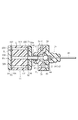
- FIG. 2 shows the liquid tank 14 of the first embodiment, which liquid tank 14 has an axis along the longitudinal axis of the aerosol inhaler when incorporated in the aerosol inhaler.
- the liquid tank 14 includes a housing 16, which has a hollow cylindrical shape extending along the axis of the liquid tank 14, and has a closed end 18 and an open end 20.
- the open end 20 is closed by an end wall 22, and the end wall 22 sandwiches an outflow valve 26 in cooperation with a partition wall 24 in the housing 16.
- the partition wall 24 partitions the inside of the housing 16 and is fixed to the peripheral wall of the housing 16 via a plurality of screws 28. Only one screw 28 is shown in FIG.
- an inner chamber 30 is defined between the closed end 18 and the partition wall 24, and the inner chamber 30 is open to the atmosphere through a plurality of vent holes 32.
- the outflow valve 26 includes a casing 34, and the casing 34 has a cylindrical casing body 36 and a flange 38 extending radially outward from the casing body 36, and the flange 38 is formed between the end wall 22 and the partition wall 24. It is sandwiched between them.
- the casing body 36 has an outer end protruding from the end wall 22, and the outer end and the end wall 22 are sealed by an O-ring 40.
- a valve chamber 42 is formed in the casing body 36, and the valve chamber 42 is formed by a tapered hole. The tapered hole opens at the inner end surface of the casing body 36, and the inner end surface faces the outer end of the casing body 36. Tapered.
- a ball 44 and a valve spring 46 are sequentially arranged as valve elements from the inner end face side of the casing 34.
- the valve spring 46 is formed of a coil spring, and the ball 44 is urged in the direction of coming out of the valve chamber 42.
- a supply thin tube 48 is disposed in the casing body 36, and this supply thin tube 48 extends from the valve chamber 42 and protrudes from the outer end of the casing body 36.
- the outflow valve 26 further includes a valve seat member 50.
- the valve seat member 50 has a stepped cylindrical shape and is held in the partition wall 24.
- the valve seat member 50 has a large-diameter end 52 and a small-diameter end.
- the large-diameter end 52 is in close contact with the inner end surface of the casing body 36 and closes the valve chamber 42.
- a hemispherical valve seat 54 is formed on the end face of the large diameter end 52, and the valve seat 54 receives the ball 44.
- a through hole 56 is formed in the valve seat member 50, and the through hole 56 opens at the center of the valve seat 54 and the end surface of the small diameter end of the valve seat member 50.
- the valve chamber 42 and the through hole 56 form a valve passage for the outflow valve 26.
- the outflow valve 26 described above is a check valve that allows only the flow from the through hole 56 toward the valve chamber 24.
- an inflow valve 58 is disposed in the inner chamber 30 described above, and the inflow valve 58 is disposed between the valve seat holder 60 and the closed end 18 of the housing 16.
- the valve seat holder 60 has a cylindrical shape and has an end face 62 that is in close contact with the partition wall 24.
- An air introduction groove 64 is formed in the end face 62, and the air introduction groove 64 extends in the radial direction of the valve seat holder 60 and opens as an air opening on the outer peripheral surface of the valve seat holder 60. That is, the atmosphere introduction groove 64 is connected to the atmosphere through the inner chamber 30 and the vent hole 32.
- the inflow valve 58 has the same structure as the outflow valve 26 described above. Therefore, in order to avoid duplication of explanation, the members of the inflow valve 58 that perform the same function as the members of the outflow valve 26 are given the same reference numerals. Hereinafter, with respect to the inflow valve 58, only differences from the outflow valve 26 will be described.
- the inflow valve 58 is disposed opposite to the outflow valve 26, and the through hole 56 of the inflow valve 58 is connected to the atmosphere introduction groove 64.
- the casing body 36 of the valve holder 60 and the inflow valve 58 are coupled to each other via a plurality of screws 66.
- connection passage 68 The inflow valve 58 and the outflow valve 26 are connected to each other via a connection passage 68.
- the connection passage 68 will be described in detail below.
- Inner passages 70, 72 are formed in the casing body 36 of the inflow valve 58 and the outflow valve 26, respectively, and these inner passages 70, 72 are formed at one end opened to the valve chamber 42 of the corresponding valve and on the outer peripheral surface of the casing body 36. It has the other end opened. Further, the internal passage 70 has an inlet opening at the end face of the casing body 36, and this inlet is closed by a plug 74.
- the other ends of the internal passages 70 and 72 are connected to each other by a coil tube 76 as a reservoir region.
- the coil tube 76 is disposed so as to surround the inflow valve 58 and extends in the inner chamber 30 in the axial direction of the liquid tank 14.
- the liquid flow path formed by the valve chamber 42 of the inflow valve 58, the connection passage 68, the valve chamber 42 of the outflow valve 26, and the supply thin tube 48 is filled with the flavor solution L.
- the flavor solution L is guided to the tip of the supply thin tube 48.
- the channel cross-sectional area of the supply thin tube 48 is sufficiently smaller than the average channel cross-sectional area of the liquid channel. Note that the flavor solution L can be injected into the liquid flow path through the aforementioned inlet.
- the tip of the supply thin tube 48 is positioned as a supply port in the suction path in the aerosol inhaler. Therefore, when the user sucks air in the suction path from the mouthpiece of the aerosol suction device, suction pressure is generated in the suction path. This suction pressure opens the outflow valve 26 and the inflow valve 58 and sucks the flavor solution L from the tip of the supply thin tube 48 into the suction path.
- the amount of the flavor solution L sucked out here that is, the amount of the flavor solution L supplied to the suction path is determined as follows.
- the tip surface of the continuous body (the tip of the supply thin tube 48). )
- the atmospheric pressure applied to the rear end of the continuum and the suction time is applied to the rear end of the continuum and the suction time.
- the flavor solution L from the supply thin tube 48 is interlocked with the suction, and the continuum of the flavor solution L advances toward the tip of the supply thin tube 48 in the liquid flow path. It will be in the state filled with the flavor solution L.
- the liquid tank 14 can stably supply the flavor solution L in the suction path. it can. Moreover, since all the flavor solution L in the liquid flow path is supplied into the suction path, the flavor solution L does not remain in the liquid flow path. Further, when no suction pressure is generated in the suction path, the outflow valve 26 and the inflow valve 58 are both closed, so that there is no possibility that the flavor solution L leaks from the tip of the supply thin tube 48 or the inflow valve 58.
- FIG. 3 shows the liquid tank 14 of the second embodiment.
- the outflow valve 26 of the second embodiment is held by a valve seat holder 78, and this valve seat holder 78 exhibits the same function as the partition wall 24 of the first embodiment.
- the valve seat holder 78 and the flange 38 of the casing 34 are coupled to each other via a plurality of screws 80.
- the valve seat holder 78 has a screw hole 81 on the outer peripheral surface thereof.
- the valve seat holder 78 has a stepped hole 82 on the surface opposite to the casing 34, and the stepped hole 82 communicates with the through hole 56 of the valve seat member 50.
- One end of a connection pipe 86 is inserted into the stepped hole 82 via a seal ring 84, and the other end of the connection pipe 86 is connected to a reservoir 88.
- the reservoir 88 includes a cylindrical block 90, and the block 90 has one end surface 90a and the other end surface 90b. Circular end walls 96 and 98 are attached to these end faces 90a and 90b via seal plates 92 and 94, respectively.
- the connection pipe 86 passes through the center of the end wall 96 and the seal plate 92, and the other end of the connection pipe 86 is in close contact with one end surface 90 a of the block 90.
- an air outlet 100 and a throttle hole 102 are formed in the outer peripheral portions of the end wall 98 and the seal plate 94, respectively.
- the atmospheric port 100 and the throttle hole 102 communicate with each other, and the inner diameter of the throttle hole 102 is smaller than the inner diameter of the atmospheric port 100.
- a zigzag connection passage is formed in the block 90 to connect the throttle hole 102 and the other end of the connection pipe 86 to each other.
- the connection passage includes a large number of through-holes 104 formed in the block 90, and these through-holes 104 pass through the block 90 along the axial direction of the block 90 and are opened at the end faces 90a and 90b. , B respectively.
- FIG. 4 shows the distribution of the openings A and B on the end faces 90a and 90b, and each through-hole 104 has the openings A and B to which the same subscript is added.
- the through hole 104 is indicated by a one-dot chain line.
- a large number of grooves 106 are formed in the end surface 90a. These grooves 106 are formed between the openings A1 and A2, between the openings A3 and A4, between the openings A5 and A6, and between the openings A7 and A8.
- opening A9 and opening A10 between opening A11 and opening A12, between opening A13 and opening A14, between opening A15 and opening A16, between opening A17 and opening A18, opening A19 and the opening A20 are connected to each other.
- a large number of grooves 108 are formed in the end face 90b. These grooves 108 are formed between the openings B2 and B3, between the openings B4 and B5, between the openings B6 and B7, and between the openings B8 and B9. , Between opening B10 and opening B11, between opening B12 and opening B13, between opening B14 and opening B15, between opening B16 and opening B17, between opening B18 and opening B19, opening B20 and the opening B21 are connected to each other.
- the through hole 104 having the openings A 1 and B 1 is disposed on the outer peripheral portion of the block 90, and the opening B 1 of the through hole 104 is connected to the atmosphere port 100 through the throttle hole 102.
- the through hole 104 having the openings A21 and B21 is positioned on the axis of the block 90, and the opening A21 of the through hole 104 is connected to the other end of the connection pipe 86 described above.
- the through hole 104 and the grooves 106 and 108 described above form one connection passage that connects the throttle hole 102 and the connection end 86. .
- the liquid flow path from the connection passage through the connection pipe 86 and the outflow valve 26 to the tip of the supply thin pipe 48 is filled with the flavor solution L.
- the flavor solution L is injected from the atmosphere port 100.
- the liquid tank 14 of the second embodiment exhibits the same function as that of the first embodiment described above.
- the inflow valve 58 is omitted. However, as long as the outflow valve 26 is closed, the flavor solution L does not leak from the atmosphere port 100.
- the liquid tank 14 of the second embodiment may further include a plug liquid 110 that is injected into the connection passage and closes the connection passage.
- the plug liquid 110 does not have affinity for the flavor solution L, and is positioned adjacent to the rear end of the continuum of the flavor solution L. Therefore, the plug liquid 110 moves forward together with the continuum of the flavor solution L, and reliably prevents the flavor solution L from being contaminated by dust or the like.
- the liquid tank 14 of the second embodiment may further include an air layer 112 between the plug liquid 110 and the rear end of the flavor solution L continuum.
- the plug liquid 110 is not required to have non-affinity with respect to the flavor solution L.
- the present invention is not limited to the liquid tanks of the first and second embodiments described above, and the specific structures of the outflow valve 26, the inflow valve 58 and the reservoir area can be variously changed.
- the supply capillary 48 of the liquid tank 14 may be a capillary that guides the flavor solution L to the tip thereof by capillary action regardless of the suction pressure in the suction path.
Abstract
エアロゾル吸引器のための液タンクは、エアロゾル吸引器の吸引経路に開口した供給口と、大気に開放された大気口と、供給口と大気口との間を接続し且つ内部に香味溶液を蓄えた液流路とを有し、この液流路の一部はコイルチューブによって形成されている。
Description
本発明は、香味溶液を供給する液タンク、詳しくは、香味溶液を香気エアロゾルに変換させ、この香気エアロゾルを空気とともにユーザに吸引させるエアロゾル吸引器に好適した液タンクに関する。
この種のエアゾル吸引器は以下の特許文献1,2にそれぞれ開示されている。特許文献1,2のエアロゾル吸引器は何れも、吸引経路及び香味溶液を蓄えた液タンクを含む。この液タンクは吸引経路内の吸引圧又は毛細管現象の働きにより、吸引経路の所定位置に香味溶液を供給する。このようなエアゾル吸引器によれば、供給位置への香味溶液の供給にあたり、駆動源、即ち、供給ポンプが不要となり、このことはエアロゾル吸引器の小形化を可能にする。
特許文献1の液タンクは、タンクボディと、このタンクボディ内の液中から吸引経路まで上方に向けて延びる供給管と、この供給管の出口に取り付けられたヒータを有する。しかしながら、供給管の出口位置は香味溶液が供給管内を毛細管現象によって上昇できる高さ以下でなければならず、液タンクの設計や配置を大きく制約する。
また、液タンク内における香味溶液の残量が少なくなるか、又は、液タンクが傾斜されている場合、供給管内での香味溶液の上昇速度が低下する。この状況下では、ヒータによる香味溶液の加熱時間が一定であっても、供給管から吸引経路内に供給される香味溶液の供給量、即ち、香味エアロゾルの生成量が減少し、香味エアロゾルの生成量を安定させることができない。
更に、液タンク内は大気口を通じて大気に開放されていなければならないので、液タンク内の香味溶液が大気口から漏れ出す虞がある。
更に、液タンク内は大気口を通じて大気に開放されていなければならないので、液タンク内の香味溶液が大気口から漏れ出す虞がある。
一方、特許文献2の液タンクはタンクボディとして香味溶液が充填された可撓性袋を含み、この可撓性袋もまた供給管を介して吸引経路の供給位置に接続されている。可撓性袋内の香味溶液は吸引経路内の吸引圧により、供給管を通じて吸引経路に供給される。可撓性袋は変形自在であるから、可撓性袋内の圧力は常時大気圧に維持され、一定である。それ故、可撓性袋から供給される香味溶液の量は吸引圧に応じて決定されることから、可撓性袋は香味溶液の安定した供給を可能にし、また、香味溶液の漏出を確実に防止する。
しかしながら、上述した香味溶液の安定供給は可撓性袋内に香味溶液が十分に蓄えられていることが条件である。詳しくは、可撓性袋内の香味溶液の残量が少なくなれば、可撓性袋自体の収縮変形に要する力が増加し、香味溶液の安定供給が維持されない。更に、特許文献1,2の液タンクは何れも、液タンク内の香味溶液を完全に供給できず、液タンクは香味溶液を残存させた状態で廃棄されるか、又は、香味溶液の補給を受けなければならない。
本発明の目的は、香味溶液の漏れや残存を防止しつつ、香味溶液の安定供給を可能にするエアロゾル吸引器のための液タンクを提供することにある。
上記目的は本発明の液タンクによって達成され、この液タンクは、エアロゾル吸引器の吸引経路に開口した供給口と、大気に開放された大気口と、供給口と大気口との間を接続し且つ内部に香味溶液を蓄えた液流路であって、供給口に吸引経路の吸引圧及び毛細管現象の一方の働きによって香味溶液を導く一方、供給口と大気口との間に香味溶液のリザーバ域を含む、液流路とを備える。
上述の液タンクによれば、吸引経路内に吸引圧が発生されたとき、液流路内の香味溶液は供給口にて受ける吸引圧と大気口を通じて受ける大気圧との間の差圧に基づき、供給口から吸引経路内に吸い出される。ここでの香味溶液の吸い出しに伴い、液流路内の香味溶液は供給口に向けて前進する。それ故、吸引経路内に吸引圧が繰り返して発生される度に、吸引経路内への香味溶液の供給及び液流路内の香味溶液の移動が繰り返され、この結果、液流路内の香味溶液はその全てが吸引経路内に供給可能である。
また、上述した差圧が発生されていないときには、液流路内の香味溶液は供給口及び大気口を通じて大気圧を受ける。それ故、例えば供給口側の液流路の部位の流路抵抗が大きければ、液流路内での香味溶液の移動、即ち、液流路の供給口又は大気口からの香味溶液の漏出は確実に阻止される。具体的には、液流路は、先端に供給口を有する供給管を更に含み、この供給管は液流路の流路断面積よりも小さい流路断面積を有する。供給管は液流路に上述した流路抵抗を提供する一方、供給口からの香味溶液の供給量を制御するうえで役立つ。
一方、液タンクは液流路に配置された流出弁を更に備えることができ、この流出弁は供給管とリザーバ域との間に位置付けられ、供給口に向かう香味溶液の流れのみを許容する。このような流出弁は大気口側に向かう香味溶液の逆流を阻止する。
また、液タンクは液流路に配置された流入弁を更に備えることができ、この流入弁は大気口とリザーバ域との間に位置付けられ、リザーバ域に向かう空気の流れのみを許容する。このような流入弁は大気口側に向かう香味溶液の逆流を阻止する。
また、液タンクは液流路に配置された流入弁を更に備えることができ、この流入弁は大気口とリザーバ域との間に位置付けられ、リザーバ域に向かう空気の流れのみを許容する。このような流入弁は大気口側に向かう香味溶液の逆流を阻止する。
更に、液タンクは液流路内を満たすプラグ液を更に含むことができ、このプラグ液は大気口と香味溶液との間に位置付けられている。具体的には、プラグ液は香味溶液に対する親和性を有さず、香味溶液に隣接しているか、又は、液タンクは液流路内にプラグ液と香味溶液を互いに分離する空気層を更に含んでいる。このようなプラグ液は液流路内の香味溶液の移動に連動して移動し、香味溶液に大気圧を伝達する一方、大気口を通じて流入する塵が香味溶液に混入するのを阻止する。
液流路のリザーバ域はコイルチューブを含むか、又は、軸線を有するリザーバと、このリザーバ内を軸線に沿ってジグザグ状に延びる通路とを含む。
液流路のリザーバ域はコイルチューブを含むか、又は、軸線を有するリザーバと、このリザーバ内を軸線に沿ってジグザグ状に延びる通路とを含む。
本発明の液タンクは、吸引経路に香味溶液を安定して供給できるばかりでなく、供給口や大気口からの香味溶液の漏れや液流路内での香味溶液の残存を確実に阻止することかできる。
図1のエアロゾル吸引器はパイプ部材2を備え、このパイプ部材2の内部は吸引経路4として形成されている。詳しくは、パイプ部材2はその一端側から空気流入セクション6、加熱セクション8及びマウスピースセクション10を含み、空気流入セクション6、即ち、吸引経路4はパイプ部材2の一端にて大気に開放された空気導入口12を有する。
空気流入セクション6には液タンク14が接続されている。この液タンク14は香味溶液を蓄えており、この香味溶液は香味エアロゾルの原料である。
空気流入セクション6には液タンク14が接続されている。この液タンク14は香味溶液を蓄えており、この香味溶液は香味エアロゾルの原料である。
ユーザがマウスピースセクション10を通じて空気を吸引すると、吸引経路4内に吸引圧が発生し、この吸引力は空気導入口12からマウスピースセクション10に向かう空気の流れを引き起こすと同時に、液タンク14から香味溶液を吸引経路4内に吸い出す。吸い出された香味溶液は空気流とともに加熱セクション8に移動し、この加熱セクション8に一旦蒸発された後、空気流中にて凝縮し、香味エアロゾルを生成する。それ故、ユーザは香味エアロゾルを空気とともに吸込み、香味エアロゾルが有する香味を味わうことができる。
図2は、第1実施例の液タンク14を示し、この液タンク14はエアロゾル吸引器に組み込まれたとき、エアロゾル吸引器の長手軸線に沿う軸線を有する。
液タンク14はハウジング16を備え、このハウジング16は液タンク14の軸線に沿って延びる中空の円筒形状をなし、閉塞端18及び開口端20を有する。この開口端20は端壁22によって閉塞され、この端壁22はハウジング16内の隔壁24と協働して流出弁26を挟持している。隔壁24はハウジング16内を仕切り、ハウジング16の周壁に複数のねじ28を介して固定されている。図2には1個のねじ28のみが示されている。ハウジング16内には閉塞端18と隔壁24との間に内室30が規定されており、この内室30は複数の通気孔32を通じて大気に開放されている。
液タンク14はハウジング16を備え、このハウジング16は液タンク14の軸線に沿って延びる中空の円筒形状をなし、閉塞端18及び開口端20を有する。この開口端20は端壁22によって閉塞され、この端壁22はハウジング16内の隔壁24と協働して流出弁26を挟持している。隔壁24はハウジング16内を仕切り、ハウジング16の周壁に複数のねじ28を介して固定されている。図2には1個のねじ28のみが示されている。ハウジング16内には閉塞端18と隔壁24との間に内室30が規定されており、この内室30は複数の通気孔32を通じて大気に開放されている。
流出弁26はケーシング34を含み、このケーシング34は円筒状のケーシングボディ36と、このケーシングボディ36から径方向外側に延びるフランジ38とを有し、このフランジ38が端壁22と隔壁24との間に挟み込まれている。ケーシングボディ36は端壁22から突出する外端を有し、この外端と端壁22との間はOリング40よってシールされている。ケーシングボディ36内には弁室42が形成され、この弁室42はテーパ孔によって形成され、このテーパ孔はケーシングボディ36の内端面に開口し、この内端面からケーシングボディ36の外端に向けて先細状となっている。
弁室42内にはケーシング34の内端面側から弁要素としてボール44及び弁ばね46が順次配置されている。この弁ばね46はコイルスプリングから形成され、ボール44は弁室42から抜け出す方向に付勢している。更に、ケーシングボディ36内には供給細管48が配置され、この供給細管48は弁室42から延び、ケーシングボディ36の外端から突出している。
流出弁26は弁座部材50を更に含む。この弁座部材50は段付きの円筒形状をなし、隔壁24内に保持されている。弁座部材50は大径端52及び小径端を有し、大径端52はケーシングボディ36の内端面に密着し、弁室42を閉じている。大径端52の端面には半球状の弁座54が形成されており、この弁座54はボール44を受け止めている。更に、弁座部材50内には貫通孔56が形成され、この貫通孔56は弁座54の中央及び弁座部材50の小径端の端面にてそれぞれ開口している。弁室42及び貫通孔56は流出弁26の弁通路を形成する。
上述した流出弁26は貫通孔56から弁室24に向かう流れのみを許容する逆止弁である。
上述した流出弁26は貫通孔56から弁室24に向かう流れのみを許容する逆止弁である。
一方、前述した内室30には流入弁58が配置されており、この流入弁58は弁座ホルダ60とハウジング16の閉塞端18との間に配置されている。弁座ホルダ60は円筒状をなし、隔壁24に密着する端面62を有する。この端面62には大気導入溝64が形成され、この大気導入溝64は弁座ホルダ60の径方向に延び、弁座ホルダ60の外周面にて大気口として開口する。即ち、大気導入溝64は内室30及び通気孔32を通じて大気に接続されている。
流入弁58は前述した流出弁26と同様な構造を有している。それ故、説明の重複を避けるため、流出弁26の部材と同様な機能を発揮する流入弁58の部材には同一の参照符号が付されている。
以下、流入弁58に関しては、流出弁26と相違する点のみを説明する。
流入弁58は流出弁26とは逆向きに配置されており、流入弁58の貫通孔56は大気導入溝64に接続されている。なお、弁ホルダ60及び流入弁58のケーシングボディ36は複数のねじ66を介して互いに結合されている。
以下、流入弁58に関しては、流出弁26と相違する点のみを説明する。
流入弁58は流出弁26とは逆向きに配置されており、流入弁58の貫通孔56は大気導入溝64に接続されている。なお、弁ホルダ60及び流入弁58のケーシングボディ36は複数のねじ66を介して互いに結合されている。
流入弁58及び流出弁26は接続通路68を介して互いに接続されており、この接続通路68について以下に詳述する。
流入弁58及び流出弁26のケーシングボディ36には内部通路70,72がそれぞれ形成され、これら内部通路70,72は対応する弁の弁室42に開口する一端と、ケーシングボディ36の外周面に開口する他端を有する。更に、内部通路70はケーシングボディ36の端面にて開口する注入口を有し、この注入口はプラグ74により閉塞されている。
流入弁58及び流出弁26のケーシングボディ36には内部通路70,72がそれぞれ形成され、これら内部通路70,72は対応する弁の弁室42に開口する一端と、ケーシングボディ36の外周面に開口する他端を有する。更に、内部通路70はケーシングボディ36の端面にて開口する注入口を有し、この注入口はプラグ74により閉塞されている。
内部通路70,72の他端はリザーバ域としてのコイルチューブ76によって互いに接続されている。このコイルチューブ76は流入弁58を囲むように配置され、内室30内を液タンク14の軸線方向に延びている。
液タンク14が初期状態にあるとき、流入弁58の弁室42、接続通路68、流出弁26の弁室42及び供給細管48から形成された液流路内は香味溶液Lで満たされ、この香味溶液Lは供給細管48の先端まで導かれている。ここで、供給細管48の流路断面積は、液流路の平均流路断面積よりも十分に小さい。なお、香味溶液Lは前述した注入口を通じて液流路内に注入可能である。
液タンク14が初期状態にあるとき、流入弁58の弁室42、接続通路68、流出弁26の弁室42及び供給細管48から形成された液流路内は香味溶液Lで満たされ、この香味溶液Lは供給細管48の先端まで導かれている。ここで、供給細管48の流路断面積は、液流路の平均流路断面積よりも十分に小さい。なお、香味溶液Lは前述した注入口を通じて液流路内に注入可能である。
上述した液タンク14がエアロゾル吸引器内に組み込まれたとき、供給細管48の先端は供給口としてエアロゾル吸引器内の吸引経路に位置付けられる。それ故、ユーザがエアロゾル吸引器のマウスピースから吸引経路内の空気を吸引したとき、吸引経路内に吸引圧が発生する。この吸引圧は流出弁26及び流入弁58を開き、供給細管48の先端から吸引経路内に香味溶液Lを吸い出す。
ここでの香味溶液Lの吸い出し量、即ち、吸引経路への香味溶液Lの供給量は、液流路内の香味溶液Lを連続体としてみたとき、連続体の先端面(供給細管48の先端)に加わる吸引圧と連続体の後端に加わる大気圧との間の差圧及び吸引時間によって決定される。そして、供給細管48からの香味溶液Lが吸い出しに連動し、香味溶液Lの連続体は液流路内を供給細管48の先端に向けて前進し、この結果、供給細管48の先端内は常時香味溶液Lで満たされた状態となる。
この結果、ユーザの吸引が繰り返される度に、香味溶液Lの供給及び香味溶液Lの連続体の前進が繰り返されるので、液タンク14は吸引経路内に香味溶液Lを安定して供給することができる。また、液流路内の香味溶液Lはその全てが吸引経路内に供給されるので、液流路内に香味溶液Lが残存することもない。
また、吸引経路内に吸引圧が発生されないとき、流出弁26及び流入弁58は共に閉じた状態にあるので、供給細管48の先端又は流入弁58から香味溶液Lが漏出する虞もない。
また、吸引経路内に吸引圧が発生されないとき、流出弁26及び流入弁58は共に閉じた状態にあるので、供給細管48の先端又は流入弁58から香味溶液Lが漏出する虞もない。
図3は、第2実施例の液タンク14を示す。
第2実施例を説明するにあたり、第1実施例の部材及び部位と同一の機能を発揮する部材及び部位には同一の参照符号が付されている。
以下、第1実施例とは相違する点について、第2実施例を説明する。
第2実施例の流出弁26は弁座ホルダ78に保持され、この弁座ホルダ78は第1実施例の隔壁24と同様な機能を発揮する。弁座ホルダ78及びケーシング34のフランジ38は複数のねじ80を介して互いに結合されている。また、弁座ホルダ78はその外周面にねじ孔81を有する。第2実施例の液タンク14が前述したハウジング16を備えている場合、ねじ孔81はハウジング16と弁座ホルダ78とを結合するねじをねじ込むために使用される。
弁座ホルダ78は、ケーシング34とは反対側の面に段付き孔82を有し、段付き孔82は弁座部材50の貫通孔56に連通している。段付き孔82にはシールリング84を介して接続管86の一端が挿入され、この接続管86の他端はリザーバ88に接続されている。
詳しくは、リザーバ88は円筒状のブロック90を含み、このブロック90は一端面90a及び他端面90bを有する。これら端面90a,90bにはシールプレート92,94を介して円形の端壁96,98がそれぞれ取り付けられている。接続管86は端壁96の中央及びシールプレート92を貫通し、接続管86の他端はブロック90の一端面90aに密着されている。
詳しくは、リザーバ88は円筒状のブロック90を含み、このブロック90は一端面90a及び他端面90bを有する。これら端面90a,90bにはシールプレート92,94を介して円形の端壁96,98がそれぞれ取り付けられている。接続管86は端壁96の中央及びシールプレート92を貫通し、接続管86の他端はブロック90の一端面90aに密着されている。
一方、端壁98及びシールプレート94の外周部には大気口100及び絞り孔102がそれぞれ形成されている。これら大気口100及び絞り孔102は互いに連通し、絞り孔102の内径は大気口100の内径よりも小さい。
ブロック90内には絞り孔102と接続管86の他端とを互いに接続するジグザグ状の接続通路が形成されている。詳しくは、接続通路はブロック90内に形成された多数の貫通孔104を含み、これら貫通孔104はブロック90の軸線方向に沿ってブロック90を貫通し、端面90a,90bにて開口した開口A,Bをそれぞれ有する。
ブロック90内には絞り孔102と接続管86の他端とを互いに接続するジグザグ状の接続通路が形成されている。詳しくは、接続通路はブロック90内に形成された多数の貫通孔104を含み、これら貫通孔104はブロック90の軸線方向に沿ってブロック90を貫通し、端面90a,90bにて開口した開口A,Bをそれぞれ有する。
図4は端面90a,90bにおける開口A,Bの分布を示し、各貫通孔104は、同一の添字が付加された開口A,Bを有する。図4中、貫通孔104は1点鎖線で示されている。
更に、端面90aには多数の溝106が形成され、これら溝106は開口A1と開口A2との間,開口A3と開口A4との間,開口A5と開口A6との間,開口A7と開口A8との間,開口A9と開口A10との間,開口A11と開口A12との間,開口A13と開口A14との間,開口A15と開口A16との間、開口A17と開口A18との間,開口A19と開口A20との間をそれぞれ接続している。
更に、端面90aには多数の溝106が形成され、これら溝106は開口A1と開口A2との間,開口A3と開口A4との間,開口A5と開口A6との間,開口A7と開口A8との間,開口A9と開口A10との間,開口A11と開口A12との間,開口A13と開口A14との間,開口A15と開口A16との間、開口A17と開口A18との間,開口A19と開口A20との間をそれぞれ接続している。
一方、端面90bには多数の溝108が形成され、これら溝108は開口B2と開口B3との間,開口B4と開口B5との間,開口B6と開口B7との間,開口B8と開口B9との間,開口B10と開口B11との間,開口B12と開口B13との間,開口B14と開口B15との間,開口B16と開口B17との間、開口B18と開口B19との間,開口B20と開口B21との間をそれぞれ接続している。
更に、開口A1,B1を有する貫通孔104はブロック90の外周部に配置され、貫通孔104の開口B1は絞り孔102を介して大気口100に接続されている。また、開口A21,B21を有する貫通孔104はブロック90の軸線上に位置付けられ、貫通孔104の開口A21は前述した接続管86の他端に接続されている。
図4中の1点鎖線に付加した矢印を参照すれば明らかなように、前述した貫通孔104及び溝106,108は、絞り孔102と接続端86とを接続する1つの接続通路を形成する。
図4中の1点鎖線に付加した矢印を参照すれば明らかなように、前述した貫通孔104及び溝106,108は、絞り孔102と接続端86とを接続する1つの接続通路を形成する。
液タンク14が初期状態にあるとき、接続通路から接続管86及び流出弁26を経て供給細管48の先端に至る液流路内は香味溶液Lで満たされている。なお、第2実施例の場合、香味溶液Lは大気口100から注入される。
第2実施例の液タンク14は前述した第1実施例と同様な機能を発揮する。なお、第2実施例の場合、流入弁58が省略されているが、流出弁26が閉じられている限り、大気口100から香味溶液Lが漏出することはない。
第2実施例の液タンク14は前述した第1実施例と同様な機能を発揮する。なお、第2実施例の場合、流入弁58が省略されているが、流出弁26が閉じられている限り、大気口100から香味溶液Lが漏出することはない。
しかしながら、第2実施例の場合、大気口100を通じて接続通路内に塵が入り込み、香味溶液Lが塵等で汚染される虞がある。このため、図5に示されるように第2実施例の液タンク14は、接続通路内に注入され、接続通路を閉塞するプラグ液110を更に含むことができる。このプラグ液110は香味溶液Lに対する親和性を有しておらず、香味溶液Lの連続体の後端に隣接して位置付けられる。それ故、プラグ液110は香味溶液Lの連続体とともに前進し、塵等による香味溶液Lの汚染を確実に防止する。
また、図6に示されているように、第2実施例の液タンク14は、プラグ液110と香味溶液Lの連続体の後端との間に空気層112を更に含むことができる。この場合、プラグ液110は香味溶液Lに対する非親和性を要求されない。
本発明は、上述した第1及び第2実施例の液タンクに制約されるものではなく、流出弁26、流入弁58及びリザーバ域の具体的に構造は種々に変更可能である。また、液タンク14の供給細管48は吸引経路内の吸引圧によらず、毛細管現象により、その先端まで香味溶液Lを導くキャピラリであってもよい。
本発明は、上述した第1及び第2実施例の液タンクに制約されるものではなく、流出弁26、流入弁58及びリザーバ域の具体的に構造は種々に変更可能である。また、液タンク14の供給細管48は吸引経路内の吸引圧によらず、毛細管現象により、その先端まで香味溶液Lを導くキャピラリであってもよい。
26 流出弁
48 供給細管(供給口)
58 流入弁
64 大気導入溝(大気口)
76 コイルチューブ(リザーバ域)
88 リザーバ
110 プラグ液
112 空気層
L 香味溶液
48 供給細管(供給口)
58 流入弁
64 大気導入溝(大気口)
76 コイルチューブ(リザーバ域)
88 リザーバ
110 プラグ液
112 空気層
L 香味溶液
Claims (9)
- 空気の吸引経路内にて香味溶液を香気エアロゾルに変換させ、この香気エアゾルを空気とともに吸引させるエアロゾル吸引器のための液タンクは、
前記吸引経路に開口した供給口と、
大気に開放された大気口と、
前記供給口と前記大気口との間を接続し且つ内部に香味溶液を蓄えた液流路であって、前記供給口に前記吸引経路の吸引圧及び毛細管現象の一方の働きによって前記香味溶液を導く一方、前記供給口と前記大気口との間に前記香味溶液のリザーバ域を含む、液流路と
具備したことを特徴とするエアロゾル吸引器のための液タンク。 - 前記液流路は、先端に前記供給口を有する供給管を更に含み、この供給管は前記液流路の流路断面積よりも小さい流路断面積を有することを特徴とする請求項1の液タンク。
- 前記液流路に配置された流出弁を更に具備し、この流出弁は前記供給管と前記リザーバ域との間に位置付けられ、前記供給口に向かう前記香味溶液の流れのみを許容することを特徴とする請求項2の液タンク。
- 前記液流路に配置された流入弁を更に具備し、この流入弁は前記大気口と前記リザーバ域との間に位置付けられ、前記リザーバ域に向かう空気の流れのみを許容することを特徴とする請求項3の液タンク。
- 前記液流路内を満たすプラグ液を更に含み、このプラグ液は前記大気口と前記香味溶液との間に位置付けられていることを特徴とする請求項3の液タンク。
- 前記プラグ液は前記香味溶液に対する親和性を有さず、前記香味溶液に隣接していることを特徴とする請求項5の液タンク。
- 前記液流路内に前記プラグ液と前記香味溶液を互いに分離する空気層を更に含むことを特徴とする請求項5の液タンク。
- 前記リザーバ域はコイルチューブを含むことを特徴とする請求項1の液タンク。
- 前記リザーバ域は、軸線を有するリザーバと、このリザーバ内を前記軸線に沿ってジグザグ状に延びる通路とを含むことを特徴とする請求項1の液タンク。
Priority Applications (8)
| Application Number | Priority Date | Filing Date | Title |
|---|---|---|---|
| PCT/JP2010/055553 WO2011121698A1 (ja) | 2010-03-29 | 2010-03-29 | エアロゾル吸引器のための液タンク |
| ES11762705.9T ES2524420T3 (es) | 2010-03-29 | 2011-03-25 | Depósito de líquido para aspirador de aerosol |
| PCT/JP2011/057351 WO2011122474A1 (ja) | 2010-03-29 | 2011-03-25 | エアロゾル吸引器のための液タンク |
| JP2012508259A JP5574510B2 (ja) | 2010-03-29 | 2011-03-25 | エアロゾル吸引器のための液タンク |
| CN201180026635.3A CN102917744B (zh) | 2010-03-29 | 2011-03-25 | 用于悬浮微粒吸入器的液罐 |
| EP11762705.9A EP2554208B1 (en) | 2010-03-29 | 2011-03-25 | Liquid tank for aerosol aspirator |
| KR1020127024209A KR101409699B1 (ko) | 2010-03-29 | 2011-03-25 | 에어로졸 흡인기를 위한 액 탱크 |
| US13/618,324 US9038626B2 (en) | 2010-03-29 | 2012-09-14 | Liquid tank for aerosol inhalator |
Applications Claiming Priority (1)
| Application Number | Priority Date | Filing Date | Title |
|---|---|---|---|
| PCT/JP2010/055553 WO2011121698A1 (ja) | 2010-03-29 | 2010-03-29 | エアロゾル吸引器のための液タンク |
Publications (1)
| Publication Number | Publication Date |
|---|---|
| WO2011121698A1 true WO2011121698A1 (ja) | 2011-10-06 |
Family
ID=44711494
Family Applications (2)
| Application Number | Title | Priority Date | Filing Date |
|---|---|---|---|
| PCT/JP2010/055553 WO2011121698A1 (ja) | 2010-03-29 | 2010-03-29 | エアロゾル吸引器のための液タンク |
| PCT/JP2011/057351 WO2011122474A1 (ja) | 2010-03-29 | 2011-03-25 | エアロゾル吸引器のための液タンク |
Family Applications After (1)
| Application Number | Title | Priority Date | Filing Date |
|---|---|---|---|
| PCT/JP2011/057351 WO2011122474A1 (ja) | 2010-03-29 | 2011-03-25 | エアロゾル吸引器のための液タンク |
Country Status (6)
| Country | Link |
|---|---|
| US (1) | US9038626B2 (ja) |
| EP (1) | EP2554208B1 (ja) |
| KR (1) | KR101409699B1 (ja) |
| CN (1) | CN102917744B (ja) |
| ES (1) | ES2524420T3 (ja) |
| WO (2) | WO2011121698A1 (ja) |
Cited By (1)
| Publication number | Priority date | Publication date | Assignee | Title |
|---|---|---|---|---|
| US9802868B2 (en) | 2012-03-01 | 2017-10-31 | Fraunhoffer-Gesellschaft Zur Foerderung Der Angewandten Forschung E. V. | Shaped sintered ceramic bodies composed of Y2O3-stabilized zirconium oxide and process for producing a shaped sintered ceramic body composed of Y2O3-stabilized zirconium oxide |
Families Citing this family (40)
| Publication number | Priority date | Publication date | Assignee | Title |
|---|---|---|---|---|
| US20160345631A1 (en) | 2005-07-19 | 2016-12-01 | James Monsees | Portable devices for generating an inhalable vapor |
| US9095175B2 (en) | 2010-05-15 | 2015-08-04 | R. J. Reynolds Tobacco Company | Data logging personal vaporizing inhaler |
| US9861772B2 (en) | 2010-05-15 | 2018-01-09 | Rai Strategic Holdings, Inc. | Personal vaporizing inhaler cartridge |
| US10159278B2 (en) | 2010-05-15 | 2018-12-25 | Rai Strategic Holdings, Inc. | Assembly directed airflow |
| US10136672B2 (en) | 2010-05-15 | 2018-11-27 | Rai Strategic Holdings, Inc. | Solderless directly written heating elements |
| US9743691B2 (en) | 2010-05-15 | 2017-08-29 | Rai Strategic Holdings, Inc. | Vaporizer configuration, control, and reporting |
| US9259035B2 (en) | 2010-05-15 | 2016-02-16 | R. J. Reynolds Tobacco Company | Solderless personal vaporizing inhaler |
| US8757147B2 (en) | 2010-05-15 | 2014-06-24 | Minusa Holdings Llc | Personal vaporizing inhaler with internal light source |
| US9999250B2 (en) | 2010-05-15 | 2018-06-19 | Rai Strategic Holdings, Inc. | Vaporizer related systems, methods, and apparatus |
| CN203152481U (zh) * | 2013-01-05 | 2013-08-28 | 刘秋明 | 电子烟 |
| US10279934B2 (en) | 2013-03-15 | 2019-05-07 | Juul Labs, Inc. | Fillable vaporizer cartridge and method of filling |
| US10638792B2 (en) | 2013-03-15 | 2020-05-05 | Juul Labs, Inc. | Securely attaching cartridges for vaporizer devices |
| US10076139B2 (en) | 2013-12-23 | 2018-09-18 | Juul Labs, Inc. | Vaporizer apparatus |
| USD842536S1 (en) | 2016-07-28 | 2019-03-05 | Juul Labs, Inc. | Vaporizer cartridge |
| PT3504991T (pt) | 2013-12-23 | 2021-03-01 | Juul Labs Int Inc | Sistemas de dispositivo e métodos de vaporização |
| USD825102S1 (en) | 2016-07-28 | 2018-08-07 | Juul Labs, Inc. | Vaporizer device with cartridge |
| US10159282B2 (en) | 2013-12-23 | 2018-12-25 | Juul Labs, Inc. | Cartridge for use with a vaporizer device |
| US10058129B2 (en) | 2013-12-23 | 2018-08-28 | Juul Labs, Inc. | Vaporization device systems and methods |
| US20160366947A1 (en) | 2013-12-23 | 2016-12-22 | James Monsees | Vaporizer apparatus |
| WO2016090303A1 (en) | 2014-12-05 | 2016-06-09 | Pax Labs, Inc. | Calibrated dose control |
| US10869502B2 (en) * | 2015-07-31 | 2020-12-22 | 14Th Round Inc. | Disposable assembly for vaporizing e-liquid and a method of using the same |
| CN205143486U (zh) * | 2015-09-02 | 2016-04-13 | 深圳市合元科技有限公司 | 雾化头、雾化器及电子烟 |
| US9844233B2 (en) * | 2015-12-15 | 2017-12-19 | Smiss Technology Co., Ltd. | Airflow preheating device |
| WO2017108429A1 (en) * | 2015-12-22 | 2017-06-29 | Philip Morris Products S.A. | Aerosol-generating system with pump |
| US10398174B2 (en) | 2015-12-22 | 2019-09-03 | Altria Client Services Llc | Aerosol-generating system with pump |
| DE202017007467U1 (de) | 2016-02-11 | 2021-12-08 | Juul Labs, Inc. | Befüllbare Verdampferkartusche |
| US10405582B2 (en) | 2016-03-10 | 2019-09-10 | Pax Labs, Inc. | Vaporization device with lip sensing |
| USD849996S1 (en) | 2016-06-16 | 2019-05-28 | Pax Labs, Inc. | Vaporizer cartridge |
| USD836541S1 (en) | 2016-06-23 | 2018-12-25 | Pax Labs, Inc. | Charging device |
| USD848057S1 (en) | 2016-06-23 | 2019-05-07 | Pax Labs, Inc. | Lid for a vaporizer |
| USD851830S1 (en) | 2016-06-23 | 2019-06-18 | Pax Labs, Inc. | Combined vaporizer tamp and pick tool |
| TWI795382B (zh) * | 2016-12-29 | 2023-03-11 | 瑞士商菲利浦莫里斯製品股份有限公司 | 匣體總成、氣溶膠傳遞系統及產生氣溶膠之方法 |
| CN109259319A (zh) * | 2017-07-17 | 2019-01-25 | 湖南中烟工业有限责任公司 | 一种雾化单元及包含该雾化单元的电子烟雾化器 |
| USD887632S1 (en) | 2017-09-14 | 2020-06-16 | Pax Labs, Inc. | Vaporizer cartridge |
| EA202190198A1 (ru) * | 2018-08-10 | 2021-06-30 | ДжейТи ИНТЕРНЕШНЛ СА | Электронная сигарета и капсула для электронной сигареты |
| US11413409B2 (en) | 2018-09-12 | 2022-08-16 | Juul Labs, Inc. | Vaporizer including positive temperature coefficient of resistivity (PTCR) heating element |
| CN113260399A (zh) * | 2018-12-31 | 2021-08-13 | 尤尔实验室有限公司 | 用于蒸发器装置的料盒 |
| US11930846B2 (en) * | 2021-03-11 | 2024-03-19 | Shenzhen Eigate Technology Co., Ltd. | Atomizer and electronic cigarette comprising the same |
| CN116963622A (zh) * | 2021-03-12 | 2023-10-27 | 菲利普莫里斯生产公司 | 用于从气溶胶形成液体生成可吸入气溶胶的气溶胶生成布置 |
| KR20230163797A (ko) * | 2022-05-24 | 2023-12-01 | 주식회사 케이티앤지 | 인헤일러 |
Citations (2)
| Publication number | Priority date | Publication date | Assignee | Title |
|---|---|---|---|---|
| JPH1189551A (ja) * | 1997-07-23 | 1999-04-06 | Japan Tobacco Inc | 香味発生装置 |
| JP2009131367A (ja) * | 2007-11-29 | 2009-06-18 | Japan Tobacco Inc | エアロゾル吸引器 |
Family Cites Families (16)
| Publication number | Priority date | Publication date | Assignee | Title |
|---|---|---|---|---|
| US4288396A (en) * | 1978-11-17 | 1981-09-08 | Ottestad Nils T | Method and device for conditioning of breathing air for divers |
| GB2251898A (en) * | 1990-11-29 | 1992-07-22 | D M W | Metered dose spray system |
| US5388574A (en) * | 1993-07-29 | 1995-02-14 | Ingebrethsen; Bradley J. | Aerosol delivery article |
| KR100289448B1 (ko) | 1997-07-23 | 2001-05-02 | 미즈노 마사루 | 향미발생장치 |
| GB9805938D0 (en) * | 1998-03-19 | 1998-05-13 | Glaxo Group Ltd | Valve for aerosol container |
| CA2445516C (en) * | 2001-04-26 | 2007-11-20 | New England Pharmaceuticals, Inc. | Metered dose delivery device for liquid and powder agents |
| DE10154237A1 (de) * | 2001-11-07 | 2003-05-15 | Steag Microparts Gmbh | Zerstäuber für manuelle Betätigung |
| JP2006511257A (ja) * | 2002-10-30 | 2006-04-06 | グラクソ グループ リミテッド | 医薬送達用システムに使用するための管状ノズル |
| US20050115992A1 (en) * | 2002-12-31 | 2005-06-02 | Ben Z. Cohen | Dispensing pump accessories for preventing the ingress or air and for aiding in alignment |
| US20050023368A1 (en) * | 2003-01-24 | 2005-02-03 | S.C. Johnson & Son, Inc. | Method of designing improved spray dispenser assemblies |
| US20060237555A1 (en) | 2005-04-11 | 2006-10-26 | Cetti Jonathan R | Systems and devices for delivering volatile materials having perfume components with a high Kovat's Index |
| CN101522244B (zh) * | 2006-08-01 | 2013-06-26 | 日本烟草产业株式会社 | 气雾吸引器 |
| US9061300B2 (en) * | 2006-12-29 | 2015-06-23 | Philip Morris Usa Inc. | Bent capillary tube aerosol generator |
| WO2009069518A1 (ja) | 2007-11-29 | 2009-06-04 | Japan Tobacco Inc. | エアロゾル吸引システム |
| US9364841B2 (en) * | 2008-02-19 | 2016-06-14 | Boehringer Ingelheim Pharma Gmbh & Co. Kg | Cartridge system |
| US20090217924A1 (en) * | 2008-02-28 | 2009-09-03 | Gregory William Pearson | Treatment systems and methods |
-
2010
- 2010-03-29 WO PCT/JP2010/055553 patent/WO2011121698A1/ja active Application Filing
-
2011
- 2011-03-25 EP EP11762705.9A patent/EP2554208B1/en active Active
- 2011-03-25 CN CN201180026635.3A patent/CN102917744B/zh active Active
- 2011-03-25 KR KR1020127024209A patent/KR101409699B1/ko active IP Right Grant
- 2011-03-25 WO PCT/JP2011/057351 patent/WO2011122474A1/ja active Application Filing
- 2011-03-25 ES ES11762705.9T patent/ES2524420T3/es active Active
-
2012
- 2012-09-14 US US13/618,324 patent/US9038626B2/en active Active
Patent Citations (2)
| Publication number | Priority date | Publication date | Assignee | Title |
|---|---|---|---|---|
| JPH1189551A (ja) * | 1997-07-23 | 1999-04-06 | Japan Tobacco Inc | 香味発生装置 |
| JP2009131367A (ja) * | 2007-11-29 | 2009-06-18 | Japan Tobacco Inc | エアロゾル吸引器 |
Cited By (1)
| Publication number | Priority date | Publication date | Assignee | Title |
|---|---|---|---|---|
| US9802868B2 (en) | 2012-03-01 | 2017-10-31 | Fraunhoffer-Gesellschaft Zur Foerderung Der Angewandten Forschung E. V. | Shaped sintered ceramic bodies composed of Y2O3-stabilized zirconium oxide and process for producing a shaped sintered ceramic body composed of Y2O3-stabilized zirconium oxide |
Also Published As
| Publication number | Publication date |
|---|---|
| CN102917744A (zh) | 2013-02-06 |
| EP2554208A1 (en) | 2013-02-06 |
| ES2524420T3 (es) | 2014-12-09 |
| EP2554208B1 (en) | 2014-11-05 |
| CN102917744B (zh) | 2015-03-18 |
| KR101409699B1 (ko) | 2014-06-19 |
| EP2554208A4 (en) | 2014-02-26 |
| US20130019862A1 (en) | 2013-01-24 |
| WO2011122474A1 (ja) | 2011-10-06 |
| KR20120129977A (ko) | 2012-11-28 |
| US9038626B2 (en) | 2015-05-26 |
Similar Documents
| Publication | Publication Date | Title |
|---|---|---|
| WO2011121698A1 (ja) | エアロゾル吸引器のための液タンク | |
| US11400243B2 (en) | Power supply section configuration for an electronic vaping device and electronic vaping device | |
| EP3340817B1 (en) | Liquid supply for electronic smoking device | |
| US20230354907A1 (en) | Electronic smoking device with refillable liquid reservoir | |
| TWI649041B (zh) | 香味吸嚐器用筒匣及香味吸嚐器 | |
| US10555554B2 (en) | Simulated cigarette | |
| AU2020269970B2 (en) | Electronic aerosol provision system | |
| US20200146351A1 (en) | Reservoir assembly for a personal vaporizer device | |
| CN109922678A (zh) | 具有可再填充的储液器的电子吸烟装置 | |
| WO2020084792A1 (ja) | カートリッジ、霧化ユニット、及び非燃焼式吸引器 | |
| CN215684876U (zh) | 雾化器及电子雾化装置 | |
| JP5574510B2 (ja) | エアロゾル吸引器のための液タンク | |
| TW201929698A (zh) | 儲液裝置 |
Legal Events
| Date | Code | Title | Description |
|---|---|---|---|
| 121 | Ep: the epo has been informed by wipo that ep was designated in this application |
Ref document number: 10848880 Country of ref document: EP Kind code of ref document: A1 |
|
| NENP | Non-entry into the national phase |
Ref country code: DE |
|
| 122 | Ep: pct application non-entry in european phase |
Ref document number: 10848880 Country of ref document: EP Kind code of ref document: A1 |
|
| NENP | Non-entry into the national phase |
Ref country code: JP |