WO2011121698A1 - Réservoir de liquide pour un aspirateur d'aérosol - Google Patents
Réservoir de liquide pour un aspirateur d'aérosol Download PDFInfo
- Publication number
- WO2011121698A1 WO2011121698A1 PCT/JP2010/055553 JP2010055553W WO2011121698A1 WO 2011121698 A1 WO2011121698 A1 WO 2011121698A1 JP 2010055553 W JP2010055553 W JP 2010055553W WO 2011121698 A1 WO2011121698 A1 WO 2011121698A1
- Authority
- WO
- WIPO (PCT)
- Prior art keywords
- liquid
- flavor solution
- liquid tank
- port
- flow path
- Prior art date
Links
Images


Classifications
-
- A—HUMAN NECESSITIES
- A61—MEDICAL OR VETERINARY SCIENCE; HYGIENE
- A61M—DEVICES FOR INTRODUCING MEDIA INTO, OR ONTO, THE BODY; DEVICES FOR TRANSDUCING BODY MEDIA OR FOR TAKING MEDIA FROM THE BODY; DEVICES FOR PRODUCING OR ENDING SLEEP OR STUPOR
- A61M11/00—Sprayers or atomisers specially adapted for therapeutic purposes
- A61M11/04—Sprayers or atomisers specially adapted for therapeutic purposes operated by the vapour pressure of the liquid to be sprayed or atomised
- A61M11/041—Sprayers or atomisers specially adapted for therapeutic purposes operated by the vapour pressure of the liquid to be sprayed or atomised using heaters
-
- A—HUMAN NECESSITIES
- A24—TOBACCO; CIGARS; CIGARETTES; SIMULATED SMOKING DEVICES; SMOKERS' REQUISITES
- A24F—SMOKERS' REQUISITES; MATCH BOXES; SIMULATED SMOKING DEVICES
- A24F40/00—Electrically operated smoking devices; Component parts thereof; Manufacture thereof; Maintenance or testing thereof; Charging means specially adapted therefor
- A24F40/10—Devices using liquid inhalable precursors
-
- A—HUMAN NECESSITIES
- A24—TOBACCO; CIGARS; CIGARETTES; SIMULATED SMOKING DEVICES; SMOKERS' REQUISITES
- A24F—SMOKERS' REQUISITES; MATCH BOXES; SIMULATED SMOKING DEVICES
- A24F40/00—Electrically operated smoking devices; Component parts thereof; Manufacture thereof; Maintenance or testing thereof; Charging means specially adapted therefor
- A24F40/30—Devices using two or more structurally separated inhalable precursors, e.g. using two liquid precursors in two cartridges
-
- A—HUMAN NECESSITIES
- A24—TOBACCO; CIGARS; CIGARETTES; SIMULATED SMOKING DEVICES; SMOKERS' REQUISITES
- A24F—SMOKERS' REQUISITES; MATCH BOXES; SIMULATED SMOKING DEVICES
- A24F40/00—Electrically operated smoking devices; Component parts thereof; Manufacture thereof; Maintenance or testing thereof; Charging means specially adapted therefor
- A24F40/40—Constructional details, e.g. connection of cartridges and battery parts
- A24F40/42—Cartridges or containers for inhalable precursors
-
- A—HUMAN NECESSITIES
- A24—TOBACCO; CIGARS; CIGARETTES; SIMULATED SMOKING DEVICES; SMOKERS' REQUISITES
- A24F—SMOKERS' REQUISITES; MATCH BOXES; SIMULATED SMOKING DEVICES
- A24F40/00—Electrically operated smoking devices; Component parts thereof; Manufacture thereof; Maintenance or testing thereof; Charging means specially adapted therefor
- A24F40/40—Constructional details, e.g. connection of cartridges and battery parts
- A24F40/48—Fluid transfer means, e.g. pumps
- A24F40/485—Valves; Apertures
-
- A—HUMAN NECESSITIES
- A61—MEDICAL OR VETERINARY SCIENCE; HYGIENE
- A61M—DEVICES FOR INTRODUCING MEDIA INTO, OR ONTO, THE BODY; DEVICES FOR TRANSDUCING BODY MEDIA OR FOR TAKING MEDIA FROM THE BODY; DEVICES FOR PRODUCING OR ENDING SLEEP OR STUPOR
- A61M11/00—Sprayers or atomisers specially adapted for therapeutic purposes
- A61M11/04—Sprayers or atomisers specially adapted for therapeutic purposes operated by the vapour pressure of the liquid to be sprayed or atomised
- A61M11/041—Sprayers or atomisers specially adapted for therapeutic purposes operated by the vapour pressure of the liquid to be sprayed or atomised using heaters
- A61M11/042—Sprayers or atomisers specially adapted for therapeutic purposes operated by the vapour pressure of the liquid to be sprayed or atomised using heaters electrical
-
- A—HUMAN NECESSITIES
- A61—MEDICAL OR VETERINARY SCIENCE; HYGIENE
- A61M—DEVICES FOR INTRODUCING MEDIA INTO, OR ONTO, THE BODY; DEVICES FOR TRANSDUCING BODY MEDIA OR FOR TAKING MEDIA FROM THE BODY; DEVICES FOR PRODUCING OR ENDING SLEEP OR STUPOR
- A61M11/00—Sprayers or atomisers specially adapted for therapeutic purposes
- A61M11/06—Sprayers or atomisers specially adapted for therapeutic purposes of the injector type
-
- A—HUMAN NECESSITIES
- A61—MEDICAL OR VETERINARY SCIENCE; HYGIENE
- A61M—DEVICES FOR INTRODUCING MEDIA INTO, OR ONTO, THE BODY; DEVICES FOR TRANSDUCING BODY MEDIA OR FOR TAKING MEDIA FROM THE BODY; DEVICES FOR PRODUCING OR ENDING SLEEP OR STUPOR
- A61M15/00—Inhalators
- A61M15/0091—Inhalators mechanically breath-triggered
- A61M15/0093—Inhalators mechanically breath-triggered without arming or cocking, e.g. acting directly on the delivery valve
-
- B—PERFORMING OPERATIONS; TRANSPORTING
- B05—SPRAYING OR ATOMISING IN GENERAL; APPLYING FLUENT MATERIALS TO SURFACES, IN GENERAL
- B05B—SPRAYING APPARATUS; ATOMISING APPARATUS; NOZZLES
- B05B7/00—Spraying apparatus for discharge of liquids or other fluent materials from two or more sources, e.g. of liquid and air, of powder and gas
- B05B7/0075—Nozzle arrangements in gas streams
-
- B—PERFORMING OPERATIONS; TRANSPORTING
- B05—SPRAYING OR ATOMISING IN GENERAL; APPLYING FLUENT MATERIALS TO SURFACES, IN GENERAL
- B05B—SPRAYING APPARATUS; ATOMISING APPARATUS; NOZZLES
- B05B7/00—Spraying apparatus for discharge of liquids or other fluent materials from two or more sources, e.g. of liquid and air, of powder and gas
- B05B7/16—Spraying apparatus for discharge of liquids or other fluent materials from two or more sources, e.g. of liquid and air, of powder and gas incorporating means for heating or cooling the material to be sprayed
- B05B7/1686—Spraying apparatus for discharge of liquids or other fluent materials from two or more sources, e.g. of liquid and air, of powder and gas incorporating means for heating or cooling the material to be sprayed involving vaporisation of the material to be sprayed or of an atomising-fluid-generating product
-
- B—PERFORMING OPERATIONS; TRANSPORTING
- B05—SPRAYING OR ATOMISING IN GENERAL; APPLYING FLUENT MATERIALS TO SURFACES, IN GENERAL
- B05B—SPRAYING APPARATUS; ATOMISING APPARATUS; NOZZLES
- B05B7/00—Spraying apparatus for discharge of liquids or other fluent materials from two or more sources, e.g. of liquid and air, of powder and gas
- B05B7/24—Spraying apparatus for discharge of liquids or other fluent materials from two or more sources, e.g. of liquid and air, of powder and gas with means, e.g. a container, for supplying liquid or other fluent material to a discharge device
- B05B7/2402—Apparatus to be carried on or by a person, e.g. by hand; Apparatus comprising containers fixed to the discharge device
- B05B7/2405—Apparatus to be carried on or by a person, e.g. by hand; Apparatus comprising containers fixed to the discharge device using an atomising fluid as carrying fluid for feeding, e.g. by suction or pressure, a carried liquid from the container to the nozzle
- B05B7/2424—Apparatus to be carried on or by a person, e.g. by hand; Apparatus comprising containers fixed to the discharge device using an atomising fluid as carrying fluid for feeding, e.g. by suction or pressure, a carried liquid from the container to the nozzle the carried liquid and the main stream of atomising fluid being brought together downstream of the container before discharge
-
- B—PERFORMING OPERATIONS; TRANSPORTING
- B05—SPRAYING OR ATOMISING IN GENERAL; APPLYING FLUENT MATERIALS TO SURFACES, IN GENERAL
- B05B—SPRAYING APPARATUS; ATOMISING APPARATUS; NOZZLES
- B05B7/00—Spraying apparatus for discharge of liquids or other fluent materials from two or more sources, e.g. of liquid and air, of powder and gas
- B05B7/24—Spraying apparatus for discharge of liquids or other fluent materials from two or more sources, e.g. of liquid and air, of powder and gas with means, e.g. a container, for supplying liquid or other fluent material to a discharge device
- B05B7/2483—Spraying apparatus for discharge of liquids or other fluent materials from two or more sources, e.g. of liquid and air, of powder and gas with means, e.g. a container, for supplying liquid or other fluent material to a discharge device the supplying means involving no pressure or aspiration, e.g. means involving gravity or capillarity
Definitions
- the present invention relates to a liquid tank for supplying a flavor solution, and more particularly, to a liquid tank suitable for an aerosol inhaler that converts a flavor solution into a fragrance aerosol and sucks the fragrance aerosol together with air.
- Each of the aerosol inhalers of Patent Documents 1 and 2 includes a suction path and a liquid tank that stores a flavor solution.
- This liquid tank supplies the flavor solution to a predetermined position of the suction path by the action of suction pressure or capillary action in the suction path.
- a drive source i.e., a supply pump
- JP 11-89551 JP (11-89551 A) International Publication No. 2009/069518 Pamphlet (WO 2009/069518 A1)
- the liquid tank of Patent Document 1 has a tank body, a supply pipe extending upward from the liquid in the tank body to the suction path, and a heater attached to the outlet of the supply pipe.
- the outlet position of the supply pipe must be below a height at which the flavor solution can rise in the supply pipe by capillary action, which greatly restricts the design and arrangement of the liquid tank.
- the rising speed of the flavor solution in the supply pipe decreases.
- the supply amount of the flavor solution supplied from the supply pipe into the suction path that is, the generation amount of the flavor aerosol is reduced, and the generation of the flavor aerosol is generated.
- the amount cannot be stabilized.
- the inside of the liquid tank must be opened to the atmosphere through the atmosphere port, the flavor solution in the liquid tank may leak out from the atmosphere port.
- the liquid tank of Patent Document 2 includes a flexible bag filled with a flavor solution as a tank body, and this flexible bag is also connected to the supply position of the suction path via a supply pipe.
- the flavor solution in the flexible bag is supplied to the suction path through the supply pipe by the suction pressure in the suction path. Since the flexible bag is deformable, the pressure in the flexible bag is always maintained at atmospheric pressure and is constant. Therefore, since the amount of the flavor solution supplied from the flexible bag is determined according to the suction pressure, the flexible bag enables a stable supply of the flavor solution and ensures leakage of the flavor solution. To prevent.
- the stable supply of the flavor solution described above is a condition that the flavor solution is sufficiently stored in the flexible bag. Specifically, if the remaining amount of the flavor solution in the flexible bag decreases, the force required for shrinkage deformation of the flexible bag itself increases, and the stable supply of the flavor solution cannot be maintained. Furthermore, none of the liquid tanks of Patent Documents 1 and 2 can completely supply the flavor solution in the liquid tank, and the liquid tank is discarded with the flavor solution remaining or is replenished with the flavor solution. have to receive.
- An object of the present invention is to provide a liquid tank for an aerosol inhaler that enables stable supply of a flavor solution while preventing leakage and remaining of the flavor solution.
- the liquid tank of the present invention which connects the supply port opened to the suction path of the aerosol inhaler, the atmospheric port opened to the atmosphere, and the supply port and the atmospheric port. And a liquid flow path in which the flavor solution is stored, wherein the flavor solution is guided to the supply port by one of the suction pressure of the suction path and capillary action, while the reservoir of the flavor solution is provided between the supply port and the atmosphere port
- the flavor solution in the liquid flow path is based on the differential pressure between the suction pressure received at the supply port and the atmospheric pressure received through the air port. , Sucked into the suction path from the supply port. As the flavor solution is sucked out here, the flavor solution in the liquid flow path advances toward the supply port. Therefore, every time suction pressure is repeatedly generated in the suction path, the supply of the flavor solution into the suction path and the movement of the flavor solution in the liquid flow path are repeated, and as a result, the flavor in the liquid flow path is changed. All of the solution can be fed into the suction path.
- the liquid channel further includes a supply pipe having a supply port at the tip, and the supply pipe has a channel cross-sectional area smaller than the channel cross-sectional area of the liquid channel.
- the supply pipe serves to control the amount of flavor solution supplied from the supply port while providing the above-described flow path resistance to the liquid flow path.
- the liquid tank may further include an outflow valve disposed in the liquid flow path, and the outflow valve is positioned between the supply pipe and the reservoir region and allows only the flow of the flavor solution toward the supply port. Such an outflow valve prevents the backflow of the flavor solution toward the air inlet side.
- the liquid tank may further include an inflow valve disposed in the liquid flow path, and the inflow valve is positioned between the atmosphere port and the reservoir area, and allows only air flow toward the reservoir area. Such an inflow valve prevents the backflow of the flavor solution toward the air inlet side.
- the liquid tank can further include a plug liquid filling the liquid flow path, and the plug liquid is positioned between the air inlet and the flavor solution.
- the plug liquid has no affinity for the flavor solution and is adjacent to the flavor solution, or the liquid tank further includes an air layer that separates the plug liquid and the flavor solution from each other in the liquid flow path. It is out.
- Such plug liquid moves in conjunction with the movement of the flavor solution in the liquid flow path, and transmits atmospheric pressure to the flavor solution, while preventing dust flowing in through the atmosphere port from being mixed into the flavor solution.
- the reservoir region of the liquid flow path includes a coil tube or includes a reservoir having an axis and a passage extending in a zigzag manner along the axis within the reservoir.
- the liquid tank of the present invention not only can stably supply the flavor solution to the suction path, but also reliably prevents leakage of the flavor solution from the supply port and the air port and the remaining of the flavor solution in the liquid channel. I can do it.
- the aerosol inhaler of FIG. 1 includes a pipe member 2, and the inside of the pipe member 2 is formed as a suction path 4.
- the pipe member 2 includes an air inflow section 6, a heating section 8, and a mouthpiece section 10 from one end side thereof.
- the air inflow section 6, that is, the suction path 4 is opened to the atmosphere at one end of the pipe member 2.
- An air inlet 12 is provided.
- a liquid tank 14 is connected to the air inflow section 6.
- the liquid tank 14 stores a flavor solution, and this flavor solution is a raw material for the flavor aerosol.
- FIG. 2 shows the liquid tank 14 of the first embodiment, which liquid tank 14 has an axis along the longitudinal axis of the aerosol inhaler when incorporated in the aerosol inhaler.
- the liquid tank 14 includes a housing 16, which has a hollow cylindrical shape extending along the axis of the liquid tank 14, and has a closed end 18 and an open end 20.
- the open end 20 is closed by an end wall 22, and the end wall 22 sandwiches an outflow valve 26 in cooperation with a partition wall 24 in the housing 16.
- the partition wall 24 partitions the inside of the housing 16 and is fixed to the peripheral wall of the housing 16 via a plurality of screws 28. Only one screw 28 is shown in FIG.
- an inner chamber 30 is defined between the closed end 18 and the partition wall 24, and the inner chamber 30 is open to the atmosphere through a plurality of vent holes 32.
- the outflow valve 26 includes a casing 34, and the casing 34 has a cylindrical casing body 36 and a flange 38 extending radially outward from the casing body 36, and the flange 38 is formed between the end wall 22 and the partition wall 24. It is sandwiched between them.
- the casing body 36 has an outer end protruding from the end wall 22, and the outer end and the end wall 22 are sealed by an O-ring 40.
- a valve chamber 42 is formed in the casing body 36, and the valve chamber 42 is formed by a tapered hole. The tapered hole opens at the inner end surface of the casing body 36, and the inner end surface faces the outer end of the casing body 36. Tapered.
- a ball 44 and a valve spring 46 are sequentially arranged as valve elements from the inner end face side of the casing 34.
- the valve spring 46 is formed of a coil spring, and the ball 44 is urged in the direction of coming out of the valve chamber 42.
- a supply thin tube 48 is disposed in the casing body 36, and this supply thin tube 48 extends from the valve chamber 42 and protrudes from the outer end of the casing body 36.
- the outflow valve 26 further includes a valve seat member 50.
- the valve seat member 50 has a stepped cylindrical shape and is held in the partition wall 24.
- the valve seat member 50 has a large-diameter end 52 and a small-diameter end.
- the large-diameter end 52 is in close contact with the inner end surface of the casing body 36 and closes the valve chamber 42.
- a hemispherical valve seat 54 is formed on the end face of the large diameter end 52, and the valve seat 54 receives the ball 44.
- a through hole 56 is formed in the valve seat member 50, and the through hole 56 opens at the center of the valve seat 54 and the end surface of the small diameter end of the valve seat member 50.
- the valve chamber 42 and the through hole 56 form a valve passage for the outflow valve 26.
- the outflow valve 26 described above is a check valve that allows only the flow from the through hole 56 toward the valve chamber 24.
- an inflow valve 58 is disposed in the inner chamber 30 described above, and the inflow valve 58 is disposed between the valve seat holder 60 and the closed end 18 of the housing 16.
- the valve seat holder 60 has a cylindrical shape and has an end face 62 that is in close contact with the partition wall 24.
- An air introduction groove 64 is formed in the end face 62, and the air introduction groove 64 extends in the radial direction of the valve seat holder 60 and opens as an air opening on the outer peripheral surface of the valve seat holder 60. That is, the atmosphere introduction groove 64 is connected to the atmosphere through the inner chamber 30 and the vent hole 32.
- the inflow valve 58 has the same structure as the outflow valve 26 described above. Therefore, in order to avoid duplication of explanation, the members of the inflow valve 58 that perform the same function as the members of the outflow valve 26 are given the same reference numerals. Hereinafter, with respect to the inflow valve 58, only differences from the outflow valve 26 will be described.
- the inflow valve 58 is disposed opposite to the outflow valve 26, and the through hole 56 of the inflow valve 58 is connected to the atmosphere introduction groove 64.
- the casing body 36 of the valve holder 60 and the inflow valve 58 are coupled to each other via a plurality of screws 66.
- connection passage 68 The inflow valve 58 and the outflow valve 26 are connected to each other via a connection passage 68.
- the connection passage 68 will be described in detail below.
- Inner passages 70, 72 are formed in the casing body 36 of the inflow valve 58 and the outflow valve 26, respectively, and these inner passages 70, 72 are formed at one end opened to the valve chamber 42 of the corresponding valve and on the outer peripheral surface of the casing body 36. It has the other end opened. Further, the internal passage 70 has an inlet opening at the end face of the casing body 36, and this inlet is closed by a plug 74.
- the other ends of the internal passages 70 and 72 are connected to each other by a coil tube 76 as a reservoir region.
- the coil tube 76 is disposed so as to surround the inflow valve 58 and extends in the inner chamber 30 in the axial direction of the liquid tank 14.
- the liquid flow path formed by the valve chamber 42 of the inflow valve 58, the connection passage 68, the valve chamber 42 of the outflow valve 26, and the supply thin tube 48 is filled with the flavor solution L.
- the flavor solution L is guided to the tip of the supply thin tube 48.
- the channel cross-sectional area of the supply thin tube 48 is sufficiently smaller than the average channel cross-sectional area of the liquid channel. Note that the flavor solution L can be injected into the liquid flow path through the aforementioned inlet.
- the tip of the supply thin tube 48 is positioned as a supply port in the suction path in the aerosol inhaler. Therefore, when the user sucks air in the suction path from the mouthpiece of the aerosol suction device, suction pressure is generated in the suction path. This suction pressure opens the outflow valve 26 and the inflow valve 58 and sucks the flavor solution L from the tip of the supply thin tube 48 into the suction path.
- the amount of the flavor solution L sucked out here that is, the amount of the flavor solution L supplied to the suction path is determined as follows.
- the tip surface of the continuous body (the tip of the supply thin tube 48). )
- the atmospheric pressure applied to the rear end of the continuum and the suction time is applied to the rear end of the continuum and the suction time.
- the flavor solution L from the supply thin tube 48 is interlocked with the suction, and the continuum of the flavor solution L advances toward the tip of the supply thin tube 48 in the liquid flow path. It will be in the state filled with the flavor solution L.
- the liquid tank 14 can stably supply the flavor solution L in the suction path. it can. Moreover, since all the flavor solution L in the liquid flow path is supplied into the suction path, the flavor solution L does not remain in the liquid flow path. Further, when no suction pressure is generated in the suction path, the outflow valve 26 and the inflow valve 58 are both closed, so that there is no possibility that the flavor solution L leaks from the tip of the supply thin tube 48 or the inflow valve 58.
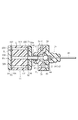
- FIG. 3 shows the liquid tank 14 of the second embodiment.
- the outflow valve 26 of the second embodiment is held by a valve seat holder 78, and this valve seat holder 78 exhibits the same function as the partition wall 24 of the first embodiment.
- the valve seat holder 78 and the flange 38 of the casing 34 are coupled to each other via a plurality of screws 80.
- the valve seat holder 78 has a screw hole 81 on the outer peripheral surface thereof.
- the valve seat holder 78 has a stepped hole 82 on the surface opposite to the casing 34, and the stepped hole 82 communicates with the through hole 56 of the valve seat member 50.
- One end of a connection pipe 86 is inserted into the stepped hole 82 via a seal ring 84, and the other end of the connection pipe 86 is connected to a reservoir 88.
- the reservoir 88 includes a cylindrical block 90, and the block 90 has one end surface 90a and the other end surface 90b. Circular end walls 96 and 98 are attached to these end faces 90a and 90b via seal plates 92 and 94, respectively.
- the connection pipe 86 passes through the center of the end wall 96 and the seal plate 92, and the other end of the connection pipe 86 is in close contact with one end surface 90 a of the block 90.
- an air outlet 100 and a throttle hole 102 are formed in the outer peripheral portions of the end wall 98 and the seal plate 94, respectively.
- the atmospheric port 100 and the throttle hole 102 communicate with each other, and the inner diameter of the throttle hole 102 is smaller than the inner diameter of the atmospheric port 100.
- a zigzag connection passage is formed in the block 90 to connect the throttle hole 102 and the other end of the connection pipe 86 to each other.
- the connection passage includes a large number of through-holes 104 formed in the block 90, and these through-holes 104 pass through the block 90 along the axial direction of the block 90 and are opened at the end faces 90a and 90b. , B respectively.
- FIG. 4 shows the distribution of the openings A and B on the end faces 90a and 90b, and each through-hole 104 has the openings A and B to which the same subscript is added.
- the through hole 104 is indicated by a one-dot chain line.
- a large number of grooves 106 are formed in the end surface 90a. These grooves 106 are formed between the openings A1 and A2, between the openings A3 and A4, between the openings A5 and A6, and between the openings A7 and A8.
- opening A9 and opening A10 between opening A11 and opening A12, between opening A13 and opening A14, between opening A15 and opening A16, between opening A17 and opening A18, opening A19 and the opening A20 are connected to each other.
- a large number of grooves 108 are formed in the end face 90b. These grooves 108 are formed between the openings B2 and B3, between the openings B4 and B5, between the openings B6 and B7, and between the openings B8 and B9. , Between opening B10 and opening B11, between opening B12 and opening B13, between opening B14 and opening B15, between opening B16 and opening B17, between opening B18 and opening B19, opening B20 and the opening B21 are connected to each other.
- the through hole 104 having the openings A 1 and B 1 is disposed on the outer peripheral portion of the block 90, and the opening B 1 of the through hole 104 is connected to the atmosphere port 100 through the throttle hole 102.
- the through hole 104 having the openings A21 and B21 is positioned on the axis of the block 90, and the opening A21 of the through hole 104 is connected to the other end of the connection pipe 86 described above.
- the through hole 104 and the grooves 106 and 108 described above form one connection passage that connects the throttle hole 102 and the connection end 86. .
- the liquid flow path from the connection passage through the connection pipe 86 and the outflow valve 26 to the tip of the supply thin pipe 48 is filled with the flavor solution L.
- the flavor solution L is injected from the atmosphere port 100.
- the liquid tank 14 of the second embodiment exhibits the same function as that of the first embodiment described above.
- the inflow valve 58 is omitted. However, as long as the outflow valve 26 is closed, the flavor solution L does not leak from the atmosphere port 100.
- the liquid tank 14 of the second embodiment may further include a plug liquid 110 that is injected into the connection passage and closes the connection passage.
- the plug liquid 110 does not have affinity for the flavor solution L, and is positioned adjacent to the rear end of the continuum of the flavor solution L. Therefore, the plug liquid 110 moves forward together with the continuum of the flavor solution L, and reliably prevents the flavor solution L from being contaminated by dust or the like.
- the liquid tank 14 of the second embodiment may further include an air layer 112 between the plug liquid 110 and the rear end of the flavor solution L continuum.
- the plug liquid 110 is not required to have non-affinity with respect to the flavor solution L.
- the present invention is not limited to the liquid tanks of the first and second embodiments described above, and the specific structures of the outflow valve 26, the inflow valve 58 and the reservoir area can be variously changed.
- the supply capillary 48 of the liquid tank 14 may be a capillary that guides the flavor solution L to the tip thereof by capillary action regardless of the suction pressure in the suction path.
Abstract
L'invention porte sur un réservoir de liquide destiné à être utilisé dans un aspirateur d'aérosol, le réservoir de liquide ayant un orifice d'alimentation qui est ouvert au passage d'aspiration de l'aspirateur d'aérosol, un orifice d'air qui est ouvert à l'air, et un canal de liquide qui relie l'orifice d'alimentation et l'orifice d'air et dans lequel une solution d'arôme est stockée, une partie du canal du liquide étant constitué d'un tube hélicoïdal.
Priority Applications (8)
| Application Number | Priority Date | Filing Date | Title |
|---|---|---|---|
| PCT/JP2010/055553 WO2011121698A1 (fr) | 2010-03-29 | 2010-03-29 | Réservoir de liquide pour un aspirateur d'aérosol |
| ES11762705.9T ES2524420T3 (es) | 2010-03-29 | 2011-03-25 | Depósito de líquido para aspirador de aerosol |
| EP11762705.9A EP2554208B1 (fr) | 2010-03-29 | 2011-03-25 | Réservoir de liquide pour un aspirateur d'aérosol |
| CN201180026635.3A CN102917744B (zh) | 2010-03-29 | 2011-03-25 | 用于悬浮微粒吸入器的液罐 |
| PCT/JP2011/057351 WO2011122474A1 (fr) | 2010-03-29 | 2011-03-25 | Réservoir de liquide pour un aspirateur d'aérosol |
| JP2012508259A JP5574510B2 (ja) | 2010-03-29 | 2011-03-25 | エアロゾル吸引器のための液タンク |
| KR1020127024209A KR101409699B1 (ko) | 2010-03-29 | 2011-03-25 | 에어로졸 흡인기를 위한 액 탱크 |
| US13/618,324 US9038626B2 (en) | 2010-03-29 | 2012-09-14 | Liquid tank for aerosol inhalator |
Applications Claiming Priority (1)
| Application Number | Priority Date | Filing Date | Title |
|---|---|---|---|
| PCT/JP2010/055553 WO2011121698A1 (fr) | 2010-03-29 | 2010-03-29 | Réservoir de liquide pour un aspirateur d'aérosol |
Publications (1)
| Publication Number | Publication Date |
|---|---|
| WO2011121698A1 true WO2011121698A1 (fr) | 2011-10-06 |
Family
ID=44711494
Family Applications (2)
| Application Number | Title | Priority Date | Filing Date |
|---|---|---|---|
| PCT/JP2010/055553 WO2011121698A1 (fr) | 2010-03-29 | 2010-03-29 | Réservoir de liquide pour un aspirateur d'aérosol |
| PCT/JP2011/057351 WO2011122474A1 (fr) | 2010-03-29 | 2011-03-25 | Réservoir de liquide pour un aspirateur d'aérosol |
Family Applications After (1)
| Application Number | Title | Priority Date | Filing Date |
|---|---|---|---|
| PCT/JP2011/057351 WO2011122474A1 (fr) | 2010-03-29 | 2011-03-25 | Réservoir de liquide pour un aspirateur d'aérosol |
Country Status (6)
| Country | Link |
|---|---|
| US (1) | US9038626B2 (fr) |
| EP (1) | EP2554208B1 (fr) |
| KR (1) | KR101409699B1 (fr) |
| CN (1) | CN102917744B (fr) |
| ES (1) | ES2524420T3 (fr) |
| WO (2) | WO2011121698A1 (fr) |
Cited By (1)
| Publication number | Priority date | Publication date | Assignee | Title |
|---|---|---|---|---|
| US9802868B2 (en) | 2012-03-01 | 2017-10-31 | Fraunhoffer-Gesellschaft Zur Foerderung Der Angewandten Forschung E. V. | Shaped sintered ceramic bodies composed of Y2O3-stabilized zirconium oxide and process for producing a shaped sintered ceramic body composed of Y2O3-stabilized zirconium oxide |
Families Citing this family (40)
| Publication number | Priority date | Publication date | Assignee | Title |
|---|---|---|---|---|
| US20160345631A1 (en) | 2005-07-19 | 2016-12-01 | James Monsees | Portable devices for generating an inhalable vapor |
| US9743691B2 (en) | 2010-05-15 | 2017-08-29 | Rai Strategic Holdings, Inc. | Vaporizer configuration, control, and reporting |
| US9095175B2 (en) | 2010-05-15 | 2015-08-04 | R. J. Reynolds Tobacco Company | Data logging personal vaporizing inhaler |
| US9259035B2 (en) | 2010-05-15 | 2016-02-16 | R. J. Reynolds Tobacco Company | Solderless personal vaporizing inhaler |
| US10136672B2 (en) | 2010-05-15 | 2018-11-27 | Rai Strategic Holdings, Inc. | Solderless directly written heating elements |
| US9861772B2 (en) | 2010-05-15 | 2018-01-09 | Rai Strategic Holdings, Inc. | Personal vaporizing inhaler cartridge |
| US8757147B2 (en) | 2010-05-15 | 2014-06-24 | Minusa Holdings Llc | Personal vaporizing inhaler with internal light source |
| US10159278B2 (en) | 2010-05-15 | 2018-12-25 | Rai Strategic Holdings, Inc. | Assembly directed airflow |
| US9999250B2 (en) | 2010-05-15 | 2018-06-19 | Rai Strategic Holdings, Inc. | Vaporizer related systems, methods, and apparatus |
| CN203152481U (zh) * | 2013-01-05 | 2013-08-28 | 刘秋明 | 电子烟 |
| US10279934B2 (en) | 2013-03-15 | 2019-05-07 | Juul Labs, Inc. | Fillable vaporizer cartridge and method of filling |
| US10638792B2 (en) | 2013-03-15 | 2020-05-05 | Juul Labs, Inc. | Securely attaching cartridges for vaporizer devices |
| DE202014011221U1 (de) | 2013-12-23 | 2018-09-13 | Juul Labs Uk Holdco Limited | Systeme für eine Verdampfungsvorrichtung |
| US10058129B2 (en) | 2013-12-23 | 2018-08-28 | Juul Labs, Inc. | Vaporization device systems and methods |
| US10076139B2 (en) | 2013-12-23 | 2018-09-18 | Juul Labs, Inc. | Vaporizer apparatus |
| US20160366947A1 (en) | 2013-12-23 | 2016-12-22 | James Monsees | Vaporizer apparatus |
| USD825102S1 (en) | 2016-07-28 | 2018-08-07 | Juul Labs, Inc. | Vaporizer device with cartridge |
| USD842536S1 (en) | 2016-07-28 | 2019-03-05 | Juul Labs, Inc. | Vaporizer cartridge |
| US10159282B2 (en) | 2013-12-23 | 2018-12-25 | Juul Labs, Inc. | Cartridge for use with a vaporizer device |
| AU2015357509B2 (en) | 2014-12-05 | 2021-05-20 | Juul Labs, Inc. | Calibrated dose control |
| US10869502B2 (en) * | 2015-07-31 | 2020-12-22 | 14Th Round Inc. | Disposable assembly for vaporizing e-liquid and a method of using the same |
| CN205143486U (zh) * | 2015-09-02 | 2016-04-13 | 深圳市合元科技有限公司 | 雾化头、雾化器及电子烟 |
| US9844233B2 (en) * | 2015-12-15 | 2017-12-19 | Smiss Technology Co., Ltd. | Airflow preheating device |
| US10398174B2 (en) | 2015-12-22 | 2019-09-03 | Altria Client Services Llc | Aerosol-generating system with pump |
| RU2725368C2 (ru) * | 2015-12-22 | 2020-07-02 | Филип Моррис Продактс С.А. | Генерирующая аэрозоль система с насосом |
| WO2017139595A1 (fr) | 2016-02-11 | 2017-08-17 | Pax Labs, Inc. | Cartouche de vaporisateur remplissable et procédé de remplissage |
| US10405582B2 (en) | 2016-03-10 | 2019-09-10 | Pax Labs, Inc. | Vaporization device with lip sensing |
| USD849996S1 (en) | 2016-06-16 | 2019-05-28 | Pax Labs, Inc. | Vaporizer cartridge |
| USD848057S1 (en) | 2016-06-23 | 2019-05-07 | Pax Labs, Inc. | Lid for a vaporizer |
| USD836541S1 (en) | 2016-06-23 | 2018-12-25 | Pax Labs, Inc. | Charging device |
| USD851830S1 (en) | 2016-06-23 | 2019-06-18 | Pax Labs, Inc. | Combined vaporizer tamp and pick tool |
| US10874818B2 (en) * | 2016-12-29 | 2020-12-29 | Philip Morris Usa Inc. | Aerosol delivery system |
| CN109259319A (zh) * | 2017-07-17 | 2019-01-25 | 湖南中烟工业有限责任公司 | 一种雾化单元及包含该雾化单元的电子烟雾化器 |
| USD887632S1 (en) | 2017-09-14 | 2020-06-16 | Pax Labs, Inc. | Vaporizer cartridge |
| KR20210038889A (ko) * | 2018-08-10 | 2021-04-08 | 제이티 인터내셔널 소시에떼 아노님 | 전자 담배 및 전자 담배용 캡슐 |
| US11413409B2 (en) | 2018-09-12 | 2022-08-16 | Juul Labs, Inc. | Vaporizer including positive temperature coefficient of resistivity (PTCR) heating element |
| WO2020142523A1 (fr) * | 2018-12-31 | 2020-07-09 | Juul Labs, Inc. | Cartouches pour dispositifs de vaporisation |
| US11930846B2 (en) * | 2021-03-11 | 2024-03-19 | Shenzhen Eigate Technology Co., Ltd. | Atomizer and electronic cigarette comprising the same |
| CN116963622A (zh) * | 2021-03-12 | 2023-10-27 | 菲利普莫里斯生产公司 | 用于从气溶胶形成液体生成可吸入气溶胶的气溶胶生成布置 |
| KR20230163797A (ko) * | 2022-05-24 | 2023-12-01 | 주식회사 케이티앤지 | 인헤일러 |
Citations (2)
| Publication number | Priority date | Publication date | Assignee | Title |
|---|---|---|---|---|
| JPH1189551A (ja) * | 1997-07-23 | 1999-04-06 | Japan Tobacco Inc | 香味発生装置 |
| JP2009131367A (ja) * | 2007-11-29 | 2009-06-18 | Japan Tobacco Inc | エアロゾル吸引器 |
Family Cites Families (16)
| Publication number | Priority date | Publication date | Assignee | Title |
|---|---|---|---|---|
| US4288396A (en) * | 1978-11-17 | 1981-09-08 | Ottestad Nils T | Method and device for conditioning of breathing air for divers |
| GB2251898A (en) * | 1990-11-29 | 1992-07-22 | D M W | Metered dose spray system |
| US5388574A (en) * | 1993-07-29 | 1995-02-14 | Ingebrethsen; Bradley J. | Aerosol delivery article |
| KR100289448B1 (ko) * | 1997-07-23 | 2001-05-02 | 미즈노 마사루 | 향미발생장치 |
| GB9805938D0 (en) * | 1998-03-19 | 1998-05-13 | Glaxo Group Ltd | Valve for aerosol container |
| WO2002092154A1 (fr) * | 2001-04-26 | 2002-11-21 | New England Pharmaceuticals, Inc. | Distributeur-doseur destine a des agents liquides et en poudre |
| DE10154237A1 (de) * | 2001-11-07 | 2003-05-15 | Steag Microparts Gmbh | Zerstäuber für manuelle Betätigung |
| WO2004041326A2 (fr) * | 2002-10-30 | 2004-05-21 | Glaxo Group Limited | Ajutages tubulaires dans des systemes servant a administrer des medicaments |
| US20050115992A1 (en) * | 2002-12-31 | 2005-06-02 | Ben Z. Cohen | Dispensing pump accessories for preventing the ingress or air and for aiding in alignment |
| US20050023368A1 (en) * | 2003-01-24 | 2005-02-03 | S.C. Johnson & Son, Inc. | Method of designing improved spray dispenser assemblies |
| US20060237555A1 (en) | 2005-04-11 | 2006-10-26 | Cetti Jonathan R | Systems and devices for delivering volatile materials having perfume components with a high Kovat's Index |
| WO2008015918A1 (fr) * | 2006-08-01 | 2008-02-07 | Japan Tobacco Inc. | Dispositif d'aspiration d'aérosol et son procédé d'aspiration |
| US9061300B2 (en) * | 2006-12-29 | 2015-06-23 | Philip Morris Usa Inc. | Bent capillary tube aerosol generator |
| WO2009069518A1 (fr) | 2007-11-29 | 2009-06-04 | Japan Tobacco Inc. | Système d'inhalation d'aérosol |
| EP2244837B1 (fr) * | 2008-02-19 | 2016-10-19 | Boehringer Ingelheim International Gmbh | Système de cartouche |
| US20090217924A1 (en) * | 2008-02-28 | 2009-09-03 | Gregory William Pearson | Treatment systems and methods |
-
2010
- 2010-03-29 WO PCT/JP2010/055553 patent/WO2011121698A1/fr active Application Filing
-
2011
- 2011-03-25 KR KR1020127024209A patent/KR101409699B1/ko active IP Right Grant
- 2011-03-25 CN CN201180026635.3A patent/CN102917744B/zh active Active
- 2011-03-25 EP EP11762705.9A patent/EP2554208B1/fr active Active
- 2011-03-25 WO PCT/JP2011/057351 patent/WO2011122474A1/fr active Application Filing
- 2011-03-25 ES ES11762705.9T patent/ES2524420T3/es active Active
-
2012
- 2012-09-14 US US13/618,324 patent/US9038626B2/en active Active
Patent Citations (2)
| Publication number | Priority date | Publication date | Assignee | Title |
|---|---|---|---|---|
| JPH1189551A (ja) * | 1997-07-23 | 1999-04-06 | Japan Tobacco Inc | 香味発生装置 |
| JP2009131367A (ja) * | 2007-11-29 | 2009-06-18 | Japan Tobacco Inc | エアロゾル吸引器 |
Cited By (1)
| Publication number | Priority date | Publication date | Assignee | Title |
|---|---|---|---|---|
| US9802868B2 (en) | 2012-03-01 | 2017-10-31 | Fraunhoffer-Gesellschaft Zur Foerderung Der Angewandten Forschung E. V. | Shaped sintered ceramic bodies composed of Y2O3-stabilized zirconium oxide and process for producing a shaped sintered ceramic body composed of Y2O3-stabilized zirconium oxide |
Also Published As
| Publication number | Publication date |
|---|---|
| KR101409699B1 (ko) | 2014-06-19 |
| ES2524420T3 (es) | 2014-12-09 |
| WO2011122474A1 (fr) | 2011-10-06 |
| EP2554208A4 (fr) | 2014-02-26 |
| KR20120129977A (ko) | 2012-11-28 |
| US20130019862A1 (en) | 2013-01-24 |
| US9038626B2 (en) | 2015-05-26 |
| CN102917744B (zh) | 2015-03-18 |
| EP2554208A1 (fr) | 2013-02-06 |
| CN102917744A (zh) | 2013-02-06 |
| EP2554208B1 (fr) | 2014-11-05 |
Similar Documents
| Publication | Publication Date | Title |
|---|---|---|
| WO2011121698A1 (fr) | Réservoir de liquide pour un aspirateur d'aérosol | |
| US11400243B2 (en) | Power supply section configuration for an electronic vaping device and electronic vaping device | |
| EP3340817B1 (fr) | Alimentation en liquide pour dispositif électronique à fumer | |
| US20230354907A1 (en) | Electronic smoking device with refillable liquid reservoir | |
| TWI649041B (zh) | 香味吸嚐器用筒匣及香味吸嚐器 | |
| US10555554B2 (en) | Simulated cigarette | |
| AU2020269970B2 (en) | Electronic aerosol provision system | |
| US20200146351A1 (en) | Reservoir assembly for a personal vaporizer device | |
| CN109922678A (zh) | 具有可再填充的储液器的电子吸烟装置 | |
| CN114340417A (zh) | 蒸发器筒以及带有这种蒸发器筒的吸入器 | |
| WO2020084792A1 (fr) | Cartouche, unité d'atomisation, et inhalateur de type sans combustion | |
| CN215684876U (zh) | 雾化器及电子雾化装置 | |
| JP5574510B2 (ja) | エアロゾル吸引器のための液タンク | |
| TW201929698A (zh) | 儲液裝置 |
Legal Events
| Date | Code | Title | Description |
|---|---|---|---|
| 121 | Ep: the epo has been informed by wipo that ep was designated in this application |
Ref document number: 10848880 Country of ref document: EP Kind code of ref document: A1 |
|
| NENP | Non-entry into the national phase |
Ref country code: DE |
|
| 122 | Ep: pct application non-entry in european phase |
Ref document number: 10848880 Country of ref document: EP Kind code of ref document: A1 |
|
| NENP | Non-entry into the national phase |
Ref country code: JP |