EP3340817B1 - Alimentation en liquide pour dispositif électronique à fumer - Google Patents
Alimentation en liquide pour dispositif électronique à fumer Download PDFInfo
- Publication number
- EP3340817B1 EP3340817B1 EP15901949.6A EP15901949A EP3340817B1 EP 3340817 B1 EP3340817 B1 EP 3340817B1 EP 15901949 A EP15901949 A EP 15901949A EP 3340817 B1 EP3340817 B1 EP 3340817B1
- Authority
- EP
- European Patent Office
- Prior art keywords
- reservoir
- liquid
- liquid supply
- housing
- piece
- Prior art date
- Legal status (The legal status is an assumption and is not a legal conclusion. Google has not performed a legal analysis and makes no representation as to the accuracy of the status listed.)
- Active
Links
- 239000007788 liquid Substances 0.000 title claims description 122
- 230000000391 smoking effect Effects 0.000 title claims description 7
- 239000000443 aerosol Substances 0.000 claims description 18
- 239000013536 elastomeric material Substances 0.000 claims description 10
- 230000008016 vaporization Effects 0.000 claims description 3
- 238000004891 communication Methods 0.000 claims description 2
- 239000012530 fluid Substances 0.000 claims description 2
- 230000006835 compression Effects 0.000 claims 1
- 238000007906 compression Methods 0.000 claims 1
- 238000009834 vaporization Methods 0.000 claims 1
- 239000003571 electronic cigarette Substances 0.000 description 17
- 239000000463 material Substances 0.000 description 11
- 239000000835 fiber Substances 0.000 description 10
- 238000010438 heat treatment Methods 0.000 description 10
- 230000008602 contraction Effects 0.000 description 6
- SNICXCGAKADSCV-JTQLQIEISA-N (-)-Nicotine Chemical compound CN1CCC[C@H]1C1=CC=CN=C1 SNICXCGAKADSCV-JTQLQIEISA-N 0.000 description 4
- 239000004917 carbon fiber Substances 0.000 description 4
- 239000003365 glass fiber Substances 0.000 description 4
- 238000000034 method Methods 0.000 description 4
- 229960002715 nicotine Drugs 0.000 description 4
- SNICXCGAKADSCV-UHFFFAOYSA-N nicotine Natural products CN1CCCC1C1=CC=CN=C1 SNICXCGAKADSCV-UHFFFAOYSA-N 0.000 description 4
- 239000004033 plastic Substances 0.000 description 4
- 229920003023 plastic Polymers 0.000 description 4
- 229920000049 Carbon (fiber) Polymers 0.000 description 3
- 238000010586 diagram Methods 0.000 description 3
- VNWKTOKETHGBQD-UHFFFAOYSA-N methane Chemical group C VNWKTOKETHGBQD-UHFFFAOYSA-N 0.000 description 3
- 229920003052 natural elastomer Polymers 0.000 description 3
- 229920001194 natural rubber Polymers 0.000 description 3
- 239000011148 porous material Substances 0.000 description 3
- 230000001105 regulatory effect Effects 0.000 description 3
- 229920003051 synthetic elastomer Polymers 0.000 description 3
- 239000005061 synthetic rubber Substances 0.000 description 3
- 230000004913 activation Effects 0.000 description 2
- 235000019504 cigarettes Nutrition 0.000 description 2
- 150000001875 compounds Chemical class 0.000 description 2
- 229920001971 elastomer Polymers 0.000 description 2
- 239000000203 mixture Substances 0.000 description 2
- 230000004044 response Effects 0.000 description 2
- 239000005060 rubber Substances 0.000 description 2
- OKTJSMMVPCPJKN-UHFFFAOYSA-N Carbon Chemical compound [C] OKTJSMMVPCPJKN-UHFFFAOYSA-N 0.000 description 1
- 239000004743 Polypropylene Substances 0.000 description 1
- 229910000831 Steel Inorganic materials 0.000 description 1
- 230000001133 acceleration Effects 0.000 description 1
- 239000000853 adhesive Substances 0.000 description 1
- 230000001070 adhesive effect Effects 0.000 description 1
- 230000033228 biological regulation Effects 0.000 description 1
- 229910052799 carbon Inorganic materials 0.000 description 1
- 239000000919 ceramic Substances 0.000 description 1
- 230000007423 decrease Effects 0.000 description 1
- 238000001514 detection method Methods 0.000 description 1
- 238000001704 evaporation Methods 0.000 description 1
- 239000011152 fibreglass Substances 0.000 description 1
- 239000000796 flavoring agent Substances 0.000 description 1
- 235000019634 flavors Nutrition 0.000 description 1
- 230000001788 irregular Effects 0.000 description 1
- 239000012528 membrane Substances 0.000 description 1
- 239000002184 metal Substances 0.000 description 1
- 229920000642 polymer Polymers 0.000 description 1
- -1 polypropylene Polymers 0.000 description 1
- 229920001155 polypropylene Polymers 0.000 description 1
- 229920000915 polyvinyl chloride Polymers 0.000 description 1
- 239000004800 polyvinyl chloride Substances 0.000 description 1
- 230000001007 puffing effect Effects 0.000 description 1
- 238000005086 pumping Methods 0.000 description 1
- 238000007789 sealing Methods 0.000 description 1
- 239000007921 spray Substances 0.000 description 1
- 239000010959 steel Substances 0.000 description 1
- XLYOFNOQVPJJNP-UHFFFAOYSA-N water Substances O XLYOFNOQVPJJNP-UHFFFAOYSA-N 0.000 description 1
- 238000003466 welding Methods 0.000 description 1
Images


Classifications
-
- A—HUMAN NECESSITIES
- A24—TOBACCO; CIGARS; CIGARETTES; SIMULATED SMOKING DEVICES; SMOKERS' REQUISITES
- A24F—SMOKERS' REQUISITES; MATCH BOXES; SIMULATED SMOKING DEVICES
- A24F40/00—Electrically operated smoking devices; Component parts thereof; Manufacture thereof; Maintenance or testing thereof; Charging means specially adapted therefor
- A24F40/40—Constructional details, e.g. connection of cartridges and battery parts
- A24F40/42—Cartridges or containers for inhalable precursors
-
- A—HUMAN NECESSITIES
- A24—TOBACCO; CIGARS; CIGARETTES; SIMULATED SMOKING DEVICES; SMOKERS' REQUISITES
- A24F—SMOKERS' REQUISITES; MATCH BOXES; SIMULATED SMOKING DEVICES
- A24F40/00—Electrically operated smoking devices; Component parts thereof; Manufacture thereof; Maintenance or testing thereof; Charging means specially adapted therefor
- A24F40/40—Constructional details, e.g. connection of cartridges and battery parts
- A24F40/44—Wicks
-
- A—HUMAN NECESSITIES
- A24—TOBACCO; CIGARS; CIGARETTES; SIMULATED SMOKING DEVICES; SMOKERS' REQUISITES
- A24F—SMOKERS' REQUISITES; MATCH BOXES; SIMULATED SMOKING DEVICES
- A24F40/00—Electrically operated smoking devices; Component parts thereof; Manufacture thereof; Maintenance or testing thereof; Charging means specially adapted therefor
- A24F40/40—Constructional details, e.g. connection of cartridges and battery parts
- A24F40/48—Fluid transfer means, e.g. pumps
- A24F40/485—Valves; Apertures
-
- A—HUMAN NECESSITIES
- A24—TOBACCO; CIGARS; CIGARETTES; SIMULATED SMOKING DEVICES; SMOKERS' REQUISITES
- A24F—SMOKERS' REQUISITES; MATCH BOXES; SIMULATED SMOKING DEVICES
- A24F40/00—Electrically operated smoking devices; Component parts thereof; Manufacture thereof; Maintenance or testing thereof; Charging means specially adapted therefor
- A24F40/10—Devices using liquid inhalable precursors
Definitions
- the rigid cartridge housing for storing liquid.
- the rigid cartridge housing has an outlet port for supplying liquid to an atomizer, and an air vent or inlet to allow air to flow into the cartridge housing.
- Air in the cartridge housing may mix with the liquid in the cartridge housing creating a gas phase.
- the gas phase can expand if ambient temperature increases, creating positive pressure in the cartridge housing, which may cause liquid to leak out of the cartridge housing.
- the gas phase in the cartridge housing may also form bubbles in the liquid which may interfere with flow of liquid to the atomizer. Accordingly, improved designs are needed.
- EP 0 244 684 A2 discloses a flavor delivery article for producing an aerosol.
- the article includes an outer container in the form of a tube and an inner container disposed within the outer container.
- the inner container contains liquid such as an alcohol-water mixture, and a delivery means such as a tube.
- An airflow acceleration means is located near the output region of the delivery means such that airflow through the outer container can disperse the liquid from the delivery means into the airflow in aerosol form.
- US 2014/190,496 A1 provides methods, devices, systems, and computer readable medium for delivering one or more compounds to a subject. Also described herein are methods, devices, systems, and computer readable medium for transitioning a smoker to an electronic nicotine delivery device and for smoking or nicotine cessation.
- US 2015/216,237 A1 deals with methods, devices, systems, and computer readable medium for delivering one or more compounds to a subject. Also described herein are methods, devices, systems, and computer readable medium for transitioning a smoker to an electronic nicotine delivery device and for smoking or nicotine urge relief.
- a liquid supply for an electronic smoking or vaporizing device has a housing.
- a reservoir is provided within the housing with at least part of the reservoir attached to the housing.
- the reservoir compensates for pressure changes and remains in position within the housing even as the volume of the reservoir decreases as liquid flows out of the reservoir. As the reservoir does not fold or collapse, liquid can continue to flow out of the reservoir freely, until the reservoir is empty.
- the liquid supply may include a liquid conducting component engaging an outlet port to transport liquid out of the reservoir and to seal the outlet port from leaking.
- the reservoir which may be provided as bottle, balloon or a bladder having an internal volume that adapts to the outflow of the liquid.
- the reservoir may be referred as a soft reservoir, although the reservoir material may or may not be soft and/or flexible.
- a reservoir can be made from elastomeric material such as natural and synthetic rubber, or from non-elastomeric material such as plastic polymers including polyvinyl chloride and polypropylene.
- the reservoir can be fully filled with liquid, with little or no gas in the reservoir, and with no air inlet or vent. As liquid from the reservoir is consumed, the reservoir contracts. No vacuum is formed within the reservoir, and no air enters into the reservoir. Without gas in the reservoir, leakage of the reservoir due to thermal expansion of gas, and generation of bubbles in the liquid, can be avoided.
- the reservoir can be pre-tensioned or elastically stretched when filled with liquid.
- the pre- tension is gradually released with the outflow of the liquid and in turn the reservoir is allowed to contract.
- Pre-tension can be applied to the reservoir by regulating pressure in the compartment.
- pretension can be applied to the reservoir by stretching an elastomeric material reservoir.
- the reservoir has an outlet to allow the liquid to flow out of the reservoir.
- the outlet may be anchored to the housing of the liquid supply.
- the housing of the liquid supply can have a tapering or conical opening, with the outlet of the reservoir constrained within the opening.
- the reservoir may have a rigid bottom that fits into the housing, to restrict the longitudinal movement of the reservoir, particularly longitudinal movement towards the outlet port.
- the reservoir may include a wick having two ends, with one end of the wick extending into the reservoir and the other end fixedly attached to the outlet. The wick may extend from the opening of the reservoir towards the bottom of the reservoir, with the wick optionally bonded to the reservoir.
- the liquid conducting component can be a gasket or pad that is in fluid communication with the wick.
- the housing can be integral one-piece member or a two-piece design.
- the housing can have a first piece and a second piece detachably connected to the first piece, with the opening positioned in the first piece and at least the bottom of the reservoir anchored to the second piece.
- the volume of the first piece may be greater than the volume of the second piece.
- a valve may be positioned between the opening of the housing and the outlet port of the reservoir.
- the housing can have an air outlet that introduces air into the space formed between the reservoir and the housing.
- the valve can be between the chamber and an air passageway connecting to the outlet of the electronic cigarette.
- the valve is opened by the sub-atmospheric pressure generated within the air passageway by a puff action of a user, and the valve is closed when the puff action ends.
- the air flow into the space during the puff action may regulate the pressure applied on the reservoir.
- This design can be especially useful when the reservoir is made from non- elastomeric material, that is, the pressure applied on the reservoir can regulate the speed of the outflow of liquid from the reservoir.
- an e-cigarette 10 typically has a housing comprising a cylindrical hollow tube having an end cap 16.
- the cylindrical hollow tube may be single piece or a multiple piece tube.
- the cylindrical hollow tube is shown as a two piece structure having a battery section 12 and an atomizer/liquid supply section 14. Together the battery section 12 and the atomizer/liquid supply section 14 form a cylindrical tube which is approximately the same size and shape as a conventional cigarette, typically about 100 mm with a 7.5 mm diameter, although lengths may range from 70 to 150 or 180 mm, and diameters from 5 to 20 mm.
- the battery section 12 and atomizer/liquid supply section 14 are typically made of steel or hardwearing plastic and act together with the end caps to provide a housing to contain the components of the e-cigarette 10.
- the battery section 12 and a atomizer/liquid supply section 14 may be configured to fit together by a friction push fit, a snap fit, or a bayonet attachment, magnetic fit, or screw threads.
- the end cap 16 is provided at the front end of the main body 12.
- the end cap 16 may be made from translucent plastic or other translucent material to allow an LED 20 positioned near the end cap to emit light through the end cap.
- the end cap can be made of metal or other materials that do not allow light to pass.
- An air outlet may be provided in the end cap, at the edge of the outlet next to the cylindrical hollow tube, anywhere along the length of the cylindrical hollow tube, or at the connection of the battery section 12 and the atomizer/liquid supply section 14.
- Figure 8 shows a pair of air outlets 38 provided at the intersection between the battery section 12 and the atomizer/liquid supply section 14 .
- a battery 18, a light emitting diode (LED) 20, control electronics 22 and optionally an airflow sensor 24 are provided within the cylindrical hollow tube battery section 12.
- the battery 18 is electrically connected to the control electronics 22, which is electrically connected to the LED 20 and the airflow sensor 24.
- the LED 20 is at the front end of the main body 12, adjacent to the end cap 16 and the control electronics 22 and airflow sensor 24 are provided in the central cavity at the other end of the battery 18 adjacent the atomizer/liquid supply section 14.
- the airflow sensor 24 acts as a puff detector, detecting a user puffing or sucking on the mouthpiece 14 of the e-cigarette 10.
- the airflow sensor 24 can be any suitable sensor for detecting changes in airflow or air pressure such a microphone switch including a deformable membrane which is caused to move by variations in air pressure.
- the sensor may be a Hall element or an electro- mechanical sensor.
- the control electronics 22 are also connected to an atomizer 26 .
- the atomizer 26 includes a heating coil 28 which is wrapped around a wick 30 extending in a passageway 32.
- the coil 28 may be positioned anywhere in the atomizer and may be transverse or parallel to the liquid supply.
- the atomizer may alternatively use other forms of heating elements, such as ceramic heaters, or fiber or mesh material heaters. Nonresistance heating elements such as sonic, piezo and jet spray may also be used in the atomizer in place of the heating coil.
- a liquid supply 34 containing a reservoir supplies liquid to the wick 30.
- the wick 30 may be a porous material such as a bundle of fiberglass fibers, with liquid in the liquid supply 34 drawn by capillary action from the ends of the wick 30 towards the central portion of the wick 30 encircled by the heating coil 28.
- An air inhalation port 36 is provided at the back end of the atomizer/liquid supply section 14 remote from the end cap 16.
- the inhalation port 36 may be formed from the cylindrical hollow tube atomizer/liquid supply section 14 or maybe formed in an end cap.
- a user sucks on the e-cigarette 10.
- This causes air to be drawn into the e-cigarette 10 via one or more air outlets, such as air outlets 38 and to be drawn through the central passage 32 towards the air inhalation port 36.
- the change in air pressure is detected by the airflow sensor 24 which generates an electrical signal that is passed to the control electronics 22.
- the control electronics 22 activates the heating coil 28 which causes liquid present in the wick 30 to be vaporized creating an aerosol (which may comprise gaseous and liquid components) within the central passage 32.
- this aerosol is drawn through the passageway 32 and inhaled by the user.
- control electronics 22 also activates the LED 20 causing the LED 20 to light up which is visible via the translucent end cap 16 simulating the appearance of a glowing ember at the end of a conventional cigarette.
- the control electronics 22 also activates the LED 20 causing the LED 20 to light up which is visible via the translucent end cap 16 simulating the appearance of a glowing ember at the end of a conventional cigarette.
- liquid present in the wick 30 is converted into an aerosol more liquid is drawn into the wick 30 from the liquid supply 34 by pressure forces, capillary action or pumping, and thus is available to be converted into an aerosol through subsequent activation of the heating coil 28.
- Some e-cigarettes are intended to be disposable and the electric power in the battery 18 is intended to be sufficient to vaporize the liquid contained within the liquid supply 34 after which the e-cigarette 10 is thrown away.
- the battery 18 is rechargeable and the liquid supply is refillable. In the cases where the liquid supply 34 is a toroidal cavity, this may be achieved by refilling the liquid supply via a refill port.
- the atomizer/liquid supply section 14 of the e-cigarette 10 is detachable from the battery section 12 and a new atomizer/liquid supply section 14 can be fitted with a new liquid supply 34 thereby replenishing the supply of liquid.
- replacing the liquid supply 34 may involve replacement of the heating coil 28 and the wick 30 along with the replacement of the liquid supply 34.
- the LED 20 may be omitted.
- the airflow sensor 24 may be placed adjacent the end cap 16 rather than in the middle of the e-cigarette.
- the airflow sensor 24 may be replaced with a switch which enables a user to activate the e-cigarette manually rather than in response to the detection of a change in air flow or air pressure.
- the atomizer may have a heating coil in a cavity in the interior of a porous body soaked in liquid.
- aerosol is generated by evaporating the liquid within the porous body either by activation of the coil heating the porous body or alternatively by the heated air passing over or through the porous body.
- the atomizer may use a piezoelectric atomizer to create an aerosol either in combination or in the absence of a heater.
- Figures 1A-1D are sectional views of a liquid supply having a housing 100 and a reservoir 200 having a main body 202 for storing liquid.
- the reservoir 200 is fitted within the housing, with a gasket 300 at an outlet port 201 of the reservoir.
- the housing 100 has a reservoir space or compartment 102 enclosed by inner walls 101, with a vent opening 104 through the housing 100 and leading into the compartment 102.
- the housing 100 may be cylindrical.
- the reservoir 200 may be made from elastomeric material, such as natural or synthetic rubber and is positioned within the compartment 102.
- the outlet port 201 of the reservoir 200 is provided for filling liquid and allowing liquid to be dispensed.
- the housing 100 may be provided with an atomizer 26, so as to be used in place of the atomizer/liquid supply section 34 shown in Fig. 8 .
- the opening 103 of the compartment 102 and the outlet port 201 of the reservoir 200 are securely connected by screw threads 400 or other attachment features such as a snap or twist fitting, adhesives, etc.
- the opening 103 of the compartment 102 can be gradually narrowed, for example via a tapered inner wall.
- the outlet port 201 is provided in a gradually narrowed contour to track the contour of the opening 103 so that the opening 103 and the outlet port 201 can be more securely connected.
- the liquid guiding gasket 300 is made from a porous material, such as fibers, fiber felt, or braided fibers for conducting liquid from the reservoir via the outlet port 201 to the atomizer of the electronic cigarette.
- the fiber can be carbon fiber, glass fiber, or mixed braided carbon fiber and glass fiber.
- the main body 202 of the reservoir 200 is made from elastomeric material. This allows a pre-tension to be applied on the main body 202 to facilitate outflow of liquid.
- the elastomeric material may be stretched as the reservoir is filled with liquid, with elastic forces maintaining the liquid under pressure in the reservoir.
- a valve may be provided at the outlet 201. When the valve is opened, liquid flows out through the outlet 201.
- the outlet 201 may be left permanently open, and the reservoir provided with a low pre-tension, just sufficient to continuously supply liquid to the atomizer.
- a reservoir fully filled with liquid can substantially occupy the entire volume of the compartment. As liquid is consumed, the reservoir contracts. The contraction of the main body 202 can be more sensitive to the sub-atmospheric pressure generated at the gasket 300 or the outlet 201 when pre-tension is applied.
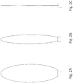
- the main body 202 can be shaped as a pillow as shown in Figures 2A-2C . That is, the main body may be rectangular or cylindrical, with flat or curved ends.
- the main body 202 can be made by bonding or welding two sheets of elastomeric material such as rubber or non-elastomeric material.
- Figures 2A-2C illustrate a fully filled reservoir, a partially contracted reservoir and a fully contracted reservoir. As shown in Figure 2C , when fully contracted, the main body 202 of the reservoir contracts to its minimum size, which may be as thin as the thickness of the two sheets of material.
- the bottom 223 of the main body 202 can be attached to an end wall 101A of the housing opposite from the opening via a rigid connector 500A.
- the anchored or connected bottom 223 prevents the main body 202 from collapsing or folding, so that flow of liquid out of the reservoir is not restricted.
- the bottom 223 of the main body can also be elastically connected to the end wall 101A of the housing via an elastic connector 500B.
- the elastic connector allows for moderate longitudinal movement of the reservoir within the compartment and reduces stress on the main body 202.
- the elastic connector 500B for example, may include a buckle 510A provided on the end wall, and a hook 520A connected to the bottom of the main body via a rubber band 530A, or vice versa.
- the main body 202 of the reservoir can additionally be fixedly connected or anchored to a side wall 101B of the housing through a rigid connection 500A.
- the side wall of the main body can also be elastically connected to the side wall of the housing through an elastic connector 500B to reduce stress of the material that made the main body.
- the connectors 500A and 500B may optionally allow the reservoir to be removed from the housing, to allow for replacement or exchange of reservoirs, optionally containing different liquids.
- the vent hole 104 allows air to be drawn into the compartment 102 as the reservoir contracts.
- a valve 121 such as a check valve, can be provided within the vent hole 104.
- the valve 121 can prevent drawing excessive air into the compartment 102 before or during contraction of the reservoir which may apply undesired pressure onto the main body of the reservoir. Therefore, the pressure within the compartment 102 can be regulated at a desired value for a smooth out flow of the liquid.
- the vent hole 104 can be provided on the end wall, the side wall or even the opening 103 of the compartment 102.
- the vent hole is provided within the opening 103 of the housing 100.
- a section of the opening 103 acts as a valve seat having a front plate 121A having a plurality of orifices 121B.
- a diaphragm 121C is mounted within the valve seat via a pin 121D.
- the diaphragm can be made from flexible material such as natural or synthetic rubber, or from a rigid material such as plastic.
- the diaphragm 121C is maintained at a closed positon when the pressure within the compartment is set at a desired initial value.
- the diagram deforms in the case of a flexible material, or displaces in the case of a rigid material, when a predetermined sub-atmospheric pressure is generated within the compartment, to allow air to be drawn through the orifices into the compartment.
- the diagram 121C returns to its closed initial position when the pressure within the compartment returns to nominal.
- a spring loaded sealing member can also be used within the valve seat to function as a check valve for regulating the pressure within the compartment and therefore achieve a pre-tensioned reservoir.
- the housing 100 can be a two-piece design, for example, as shown in Figure 5A .
- the housing 100 can have a first piece 100A that accommodates the main body of the reservoir and a second piece 100B for accommodating the outlet port of the reservoir, with the housing made from rigid material.
- the second piece of the housing can also have a holder 103B for fitting in the liquid guiding gasket.
- the housing 100 may be cylindrical, or another shape, such as cubic, conical, trapezoidal or other regular or irregular shape, with the reservoir optionally having a matching shape.
- the housing may be provided as a cartridge or cartomizer, with screw threads, lugs, etc. for attaching the housing to another e-cigarette component, such as a battery housing.
- a wick 400 may be provided within the reservoir 200 to assist in conveying liquid out to the liquid guiding gasket 300. If used, one end of the wick 400 extends through the outlet port of the reservoir into the main body, while the other end of the wick is in contact with liquid guiding gasket.
- the end of the wick within the main body can be divided into two, three, four or more sections, to maximize surface contact with the liquid.
- the end of the wick within the main body can extend to the longitudinal maximum length of the main body to provide maximized contacting area.
- the wick can be made from porous material, fibers, braided fibers, or fiber felt.
- the fiber used can be carbon fiber, glass fiber, or mixed braided carbon and glass fibers.
- the reservoir 200 has an outlet port 201, a main body 202 and a rigid bottom 203.
- the housing 100 has protrusions or a bulge 106 on its inner surface so that the compartment within the housing is segmented into a first section 102A and a second section 102B.
- the first second 102A is configured to accommodate the rigid bottom portion 203 of the reservoir so that longitudinal movement and lateral movement of the rigid bottom portion is constrained with the first section of the compartment 102A.
- the first compartment 102A may be designed to have a dimension adapted to fit the bottom portion of the main body so that the bottom portion is substantially fixed within the first compartment.
- the side of the main body can be fixedly attached, anchored, or elastically connected to the inner surface of the second section of the compartment.
- a vent hole can be provided within the opening of the housing to allow pressure regulation within the compartment.
- a liquid guiding pad can be used instead of a gasket, with the pad in contact with the outlet port of the reservoir and/or the wick.
- the liquid guiding pad can have a laminated structure.
- an aerosol channel can be provided along the perimeter of the housing to allow aerosol generated on a first side of the liquid supply to be delivered to a second side of the liquid supply which is opposite to the first side.
- the liquid supply does not contain an aerosol channel when the aerosol outlet and the atomizer are arranged on a same side of the liquid supply.
- the liquid supply has a central aerosol channel 32 that is parallel to the longitudinal axis of the housing 100.
- the inner surface of the housing forms a toroidal compartment 102.
- a reservoir 200 is positioned within the toroidal compartment 102 and is wrapped around the aerosol channel 32.
- the bottom of the main body 202 is fixedly connected to the bottom of the housing via rigid connection or elastic connections, and the side of the main body is optionally connected to the side wall of the housing via rigid or elastic connections.
- the main body 202 can have more than one outlet port 201, in this case, two outlet ports, to dispense liquid to the liquid guiding component 300.
Claims (15)
- Alimentation en liquide (14) pour un dispositif de cigarette électronique (10) ayantun boîtier (100) ayant un compartiment (102) ; et un réservoir (200) dans le compartiment (102) avec au moins une partie du réservoir (200) attachée au boîtier (100) ;le réservoir (200) ayant un volume qui varie avec des changements de pression dans le compartiment (102), et avec une quantité de liquide dans le réservoir (200) ; etcaractérisée parle fait que le réservoir (200) maintient sa position longitudinale dans le compartiment (102) lorsque du liquide est ôté du réservoir (200).
- Alimentation en liquide selon la revendication 1, le réservoir comprenant un matériau élastomère.
- Alimentation en liquide selon la revendication 1, le réservoir étant précontraint par remplissage du réservoir avec du liquide, le réservoir exerçant une force de compression élastique sur le liquide dans le réservoir.
- Alimentation en liquide selon la revendication 1, le réservoir ayant une sortie attachée de façon fixe au boîtier de l'alimentation en liquide, ou contraint dans une ouverture rétrécissant radialement dans le boîtier.
- Alimentation en liquide selon la revendication 1, le réservoir ayant un fond rigide fixé dans un bombement dans le boîtier, pour restreindre le mouvement longitudinal du fond rigide dans le boîtier.
- Alimentation en liquide selon la revendication 4, première alternative, comprenant en outre un composant conducteur de liquide s'engageant dans la sortie.
- Aliment en liquide selon la revendication 4, première alternative, le réservoir comprenant en outre une mèche ayant deux extrémités, avec une extrémité de la mèche s'étendant dans le réservoir et avec l'autre extrémité attachée de façon fixe à la sortie.
- Alimentation en liquide selon la revendication 7, la mèche s'étendant le long de l'épaisseur du réservoir, de l'ouverture vers le fond du réservoir.
- Alimentation en liquide selon la revendication 8, la mèche étant liée au réservoir.
- Alimentation en liquide selon la revendication 6, le composant conducteur de liquide étant en communication fluide avec une mèche.
- Alimentation en liquide selon la revendication 1, le boîtier comprenant une première pièce et une deuxième pièce, la première pièce étant reliée de façon détachable à la deuxième pièce, une sortie étant positionnée dans la première pièce et au moins le fond du réservoir étant ancré sur la deuxième pièce.
- Alimentation en liquide selon la revendication 11, le volume de la première pièce étant supérieur au volume de la deuxième pièce.
- Alimentation en liquide selon la revendication 1, des côtés du réservoir étant ancrés au boîtier.
- Alimentation en liquide selon la revendication 1, le boîtier comprenant en outre un évent menant au compartiment ; et une soupape positionnée dans l'évent pour réguler la pression dans le compartiment.
- Dispositif de cigarette électronique (10) comprenantun boîtier ayant une admission d'air (38) et une sortie d'aérosol (36),une alimentation en liquide (14) contenant du liquide selon l'une quelconque des revendications précédentes,un atomiseur (26) pour vaporiser du liquide fourni par l'alimentation en liquide (14),une électronique de commande électriquement connectée à l'atomiseur (26) pour réguler la vaporisation du liquide,de l'air aspiré par l'admission d'air (38) se mélangeant avec le liquide vaporisé pour générer un aérosol devant être fourni à la sortie d'aérosol (36).
Applications Claiming Priority (1)
| Application Number | Priority Date | Filing Date | Title |
|---|---|---|---|
| PCT/CN2015/087980 WO2017031678A1 (fr) | 2015-08-25 | 2015-08-25 | Alimentation en liquide pour dispositif électronique à fumer |
Publications (3)
| Publication Number | Publication Date |
|---|---|
| EP3340817A1 EP3340817A1 (fr) | 2018-07-04 |
| EP3340817A4 EP3340817A4 (fr) | 2018-09-05 |
| EP3340817B1 true EP3340817B1 (fr) | 2020-08-05 |
Family
ID=58099411
Family Applications (1)
| Application Number | Title | Priority Date | Filing Date |
|---|---|---|---|
| EP15901949.6A Active EP3340817B1 (fr) | 2015-08-25 | 2015-08-25 | Alimentation en liquide pour dispositif électronique à fumer |
Country Status (4)
| Country | Link |
|---|---|
| US (1) | US11083221B2 (fr) |
| EP (1) | EP3340817B1 (fr) |
| CN (1) | CN108024575A (fr) |
| WO (1) | WO2017031678A1 (fr) |
Families Citing this family (28)
| Publication number | Priority date | Publication date | Assignee | Title |
|---|---|---|---|---|
| US20160345631A1 (en) | 2005-07-19 | 2016-12-01 | James Monsees | Portable devices for generating an inhalable vapor |
| US10279934B2 (en) | 2013-03-15 | 2019-05-07 | Juul Labs, Inc. | Fillable vaporizer cartridge and method of filling |
| US10638792B2 (en) | 2013-03-15 | 2020-05-05 | Juul Labs, Inc. | Securely attaching cartridges for vaporizer devices |
| US10058129B2 (en) | 2013-12-23 | 2018-08-28 | Juul Labs, Inc. | Vaporization device systems and methods |
| USD825102S1 (en) | 2016-07-28 | 2018-08-07 | Juul Labs, Inc. | Vaporizer device with cartridge |
| DE202014011221U1 (de) | 2013-12-23 | 2018-09-13 | Juul Labs Uk Holdco Limited | Systeme für eine Verdampfungsvorrichtung |
| US10076139B2 (en) | 2013-12-23 | 2018-09-18 | Juul Labs, Inc. | Vaporizer apparatus |
| USD842536S1 (en) | 2016-07-28 | 2019-03-05 | Juul Labs, Inc. | Vaporizer cartridge |
| US20160366947A1 (en) | 2013-12-23 | 2016-12-22 | James Monsees | Vaporizer apparatus |
| US10159282B2 (en) | 2013-12-23 | 2018-12-25 | Juul Labs, Inc. | Cartridge for use with a vaporizer device |
| AU2015357509B2 (en) | 2014-12-05 | 2021-05-20 | Juul Labs, Inc. | Calibrated dose control |
| WO2017139595A1 (fr) | 2016-02-11 | 2017-08-17 | Pax Labs, Inc. | Cartouche de vaporisateur remplissable et procédé de remplissage |
| US10405582B2 (en) | 2016-03-10 | 2019-09-10 | Pax Labs, Inc. | Vaporization device with lip sensing |
| USD849996S1 (en) | 2016-06-16 | 2019-05-28 | Pax Labs, Inc. | Vaporizer cartridge |
| USD836541S1 (en) | 2016-06-23 | 2018-12-25 | Pax Labs, Inc. | Charging device |
| USD848057S1 (en) | 2016-06-23 | 2019-05-07 | Pax Labs, Inc. | Lid for a vaporizer |
| USD851830S1 (en) | 2016-06-23 | 2019-06-18 | Pax Labs, Inc. | Combined vaporizer tamp and pick tool |
| US10285444B2 (en) * | 2017-04-27 | 2019-05-14 | Rai Strategic Holdings, Inc. | Aerosol delivery device including a ceramic wicking element |
| USD887632S1 (en) | 2017-09-14 | 2020-06-16 | Pax Labs, Inc. | Vaporizer cartridge |
| EP3794994A1 (fr) * | 2019-09-20 | 2021-03-24 | Nerudia Limited | Composant de substitution du tabac |
| WO2021053109A1 (fr) * | 2019-09-20 | 2021-03-25 | Nerudia Limited | Composant de substitution au tabac |
| WO2021089656A1 (fr) * | 2019-11-07 | 2021-05-14 | Jt International Sa | Cartouche pour cigarette électronique |
| USD920570S1 (en) | 2019-11-13 | 2021-05-25 | Canopy Growth Corporation | Vaporizer cartridge |
| USD920571S1 (en) | 2019-11-20 | 2021-05-25 | Canopy Growth Corporation | Vaporizer cartridge |
| EP3858160A1 (fr) * | 2020-01-30 | 2021-08-04 | Nerudia Limited | Système de substitution du tabac |
| EP3861875A1 (fr) * | 2020-02-05 | 2021-08-11 | JT International SA | Cartomiseur sous pression |
| US20220264945A1 (en) * | 2021-02-25 | 2022-08-25 | 2792684 Ontario Inc. | Container assembly |
| GB2622245A (en) * | 2022-09-08 | 2024-03-13 | Inlab Ventures Ltd | Device |
Family Cites Families (16)
| Publication number | Priority date | Publication date | Assignee | Title |
|---|---|---|---|---|
| US4765347A (en) | 1986-05-09 | 1988-08-23 | R. J. Reynolds Tobacco Company | Aerosol flavor delivery system |
| CA2520759C (fr) * | 2003-04-01 | 2008-09-30 | Shusei Takano | Tuyau d'aspiration de nicotine et support de nicotine |
| CN100381083C (zh) * | 2003-04-29 | 2008-04-16 | 韩力 | 一种非可燃性电子喷雾香烟 |
| CN101084801A (zh) * | 2003-04-29 | 2007-12-12 | 韩力 | 一种非可燃性电子喷雾香烟 |
| US8528569B1 (en) * | 2011-06-28 | 2013-09-10 | Kyle D. Newton | Electronic cigarette with liquid reservoir |
| UA111630C2 (uk) * | 2011-10-06 | 2016-05-25 | Сіс Рісорсез Лтд. | Система для паління |
| UA113868C2 (xx) * | 2012-02-22 | 2017-03-27 | Електронний курильний виріб | |
| SG11201504008PA (en) * | 2012-11-28 | 2015-06-29 | Nicotine Technology Inc E | Methods and devices for compound delivery |
| WO2015013329A1 (fr) | 2013-07-25 | 2015-01-29 | Altria Client Services Inc. | Article à fumer électronique |
| CN203646499U (zh) | 2013-10-12 | 2014-06-18 | 戴伟 | 吸力供液的电子烟 |
| CN104544565B (zh) | 2013-10-12 | 2018-12-14 | 戴伟 | 吸力供液的电子烟 |
| JP6675983B2 (ja) * | 2013-12-11 | 2020-04-08 | ジェイティー インターナショナル エス.エイ. | 吸入器用の加熱システム及び加熱方法 |
| US20150216237A1 (en) * | 2014-01-22 | 2015-08-06 | E-Nicotine Technology, Inc. | Methods and devices for smoking urge relief |
| CN204070556U (zh) | 2014-07-30 | 2015-01-07 | 深圳市合元科技有限公司 | 电子烟用雾化器和电子烟 |
| CN104351949B (zh) | 2014-11-12 | 2017-08-04 | 湖南中烟工业有限责任公司 | 一种电子烟雾化器贮油装置 |
| CN104720116B (zh) * | 2015-01-30 | 2018-03-06 | 林光榕 | 电子烟雾化器 |
-
2015
- 2015-08-25 EP EP15901949.6A patent/EP3340817B1/fr active Active
- 2015-08-25 US US15/752,225 patent/US11083221B2/en active Active
- 2015-08-25 CN CN201580083110.1A patent/CN108024575A/zh active Pending
- 2015-08-25 WO PCT/CN2015/087980 patent/WO2017031678A1/fr active Application Filing
Non-Patent Citations (1)
| Title |
|---|
| None * |
Also Published As
| Publication number | Publication date |
|---|---|
| CN108024575A (zh) | 2018-05-11 |
| EP3340817A4 (fr) | 2018-09-05 |
| WO2017031678A1 (fr) | 2017-03-02 |
| US20200146350A1 (en) | 2020-05-14 |
| EP3340817A1 (fr) | 2018-07-04 |
| US11083221B2 (en) | 2021-08-10 |
Similar Documents
| Publication | Publication Date | Title |
|---|---|---|
| EP3340817B1 (fr) | Alimentation en liquide pour dispositif électronique à fumer | |
| US11076641B2 (en) | Liquid supply with sealing agent in a spiral container | |
| US20230354907A1 (en) | Electronic smoking device with refillable liquid reservoir | |
| US10792685B2 (en) | Liquid supply for an electronic smoking device | |
| US11058151B2 (en) | Refill adapter cap for a refill receptacle to refill liquid in an electronic smoking device | |
| CN108348007B (zh) | 具有可变容积的液体储存器的电子吸烟装置 | |
| EP3143884B1 (fr) | Dispositif à fumer électronique pourvu d'un réservoir de liquide rechargeable | |
| US11877599B2 (en) | Electronic smoking device with capillary buffer | |
| US11560271B2 (en) | Liquid containers for electronic smoking device | |
| US11571024B2 (en) | Electronic smoking device with refillable liquid reservoir | |
| US11470884B2 (en) | Electronic smoking device with liquid filling valve | |
| EP3498114B1 (fr) | Dispositif à fumer électronique pourvu d'un conduit de liquide |
Legal Events
| Date | Code | Title | Description |
|---|---|---|---|
| STAA | Information on the status of an ep patent application or granted ep patent |
Free format text: STATUS: THE INTERNATIONAL PUBLICATION HAS BEEN MADE |
|
| PUAI | Public reference made under article 153(3) epc to a published international application that has entered the european phase |
Free format text: ORIGINAL CODE: 0009012 |
|
| STAA | Information on the status of an ep patent application or granted ep patent |
Free format text: STATUS: REQUEST FOR EXAMINATION WAS MADE |
|
| 17P | Request for examination filed |
Effective date: 20180222 |
|
| AK | Designated contracting states |
Kind code of ref document: A1 Designated state(s): AL AT BE BG CH CY CZ DE DK EE ES FI FR GB GR HR HU IE IS IT LI LT LU LV MC MK MT NL NO PL PT RO RS SE SI SK SM TR |
|
| AX | Request for extension of the european patent |
Extension state: BA ME |
|
| A4 | Supplementary search report drawn up and despatched |
Effective date: 20180803 |
|
| RIC1 | Information provided on ipc code assigned before grant |
Ipc: A24F 47/00 20060101AFI20180730BHEP |
|
| DAV | Request for validation of the european patent (deleted) | ||
| DAX | Request for extension of the european patent (deleted) | ||
| REG | Reference to a national code |
Ref country code: DE Ref legal event code: R079 Ref document number: 602015057211 Country of ref document: DE Free format text: PREVIOUS MAIN CLASS: A24F0047000000 Ipc: A24F0040100000 |
|
| GRAP | Despatch of communication of intention to grant a patent |
Free format text: ORIGINAL CODE: EPIDOSNIGR1 |
|
| STAA | Information on the status of an ep patent application or granted ep patent |
Free format text: STATUS: GRANT OF PATENT IS INTENDED |
|
| RIC1 | Information provided on ipc code assigned before grant |
Ipc: A24F 40/42 20200101ALI20200304BHEP Ipc: A24F 40/40 20200101ALI20200304BHEP Ipc: A24F 40/10 20200101AFI20200304BHEP |
|
| INTG | Intention to grant announced |
Effective date: 20200325 |
|
| GRAS | Grant fee paid |
Free format text: ORIGINAL CODE: EPIDOSNIGR3 |
|
| GRAA | (expected) grant |
Free format text: ORIGINAL CODE: 0009210 |
|
| STAA | Information on the status of an ep patent application or granted ep patent |
Free format text: STATUS: THE PATENT HAS BEEN GRANTED |
|
| AK | Designated contracting states |
Kind code of ref document: B1 Designated state(s): AL AT BE BG CH CY CZ DE DK EE ES FI FR GB GR HR HU IE IS IT LI LT LU LV MC MK MT NL NO PL PT RO RS SE SI SK SM TR |
|
| REG | Reference to a national code |
Ref country code: GB Ref legal event code: FG4D |
|
| REG | Reference to a national code |
Ref country code: CH Ref legal event code: EP |
|
| REG | Reference to a national code |
Ref country code: AT Ref legal event code: REF Ref document number: 1297463 Country of ref document: AT Kind code of ref document: T Effective date: 20200815 |
|
| REG | Reference to a national code |
Ref country code: DE Ref legal event code: R096 Ref document number: 602015057211 Country of ref document: DE |
|
| REG | Reference to a national code |
Ref country code: IE Ref legal event code: FG4D |
|
| REG | Reference to a national code |
Ref country code: NL Ref legal event code: FP |
|
| REG | Reference to a national code |
Ref country code: LT Ref legal event code: MG4D |
|
| REG | Reference to a national code |
Ref country code: AT Ref legal event code: MK05 Ref document number: 1297463 Country of ref document: AT Kind code of ref document: T Effective date: 20200805 |
|
| PG25 | Lapsed in a contracting state [announced via postgrant information from national office to epo] |
Ref country code: AT Free format text: LAPSE BECAUSE OF FAILURE TO SUBMIT A TRANSLATION OF THE DESCRIPTION OR TO PAY THE FEE WITHIN THE PRESCRIBED TIME-LIMIT Effective date: 20200805 Ref country code: SE Free format text: LAPSE BECAUSE OF FAILURE TO SUBMIT A TRANSLATION OF THE DESCRIPTION OR TO PAY THE FEE WITHIN THE PRESCRIBED TIME-LIMIT Effective date: 20200805 Ref country code: LT Free format text: LAPSE BECAUSE OF FAILURE TO SUBMIT A TRANSLATION OF THE DESCRIPTION OR TO PAY THE FEE WITHIN THE PRESCRIBED TIME-LIMIT Effective date: 20200805 Ref country code: BG Free format text: LAPSE BECAUSE OF FAILURE TO SUBMIT A TRANSLATION OF THE DESCRIPTION OR TO PAY THE FEE WITHIN THE PRESCRIBED TIME-LIMIT Effective date: 20201105 Ref country code: NO Free format text: LAPSE BECAUSE OF FAILURE TO SUBMIT A TRANSLATION OF THE DESCRIPTION OR TO PAY THE FEE WITHIN THE PRESCRIBED TIME-LIMIT Effective date: 20201105 Ref country code: GR Free format text: LAPSE BECAUSE OF FAILURE TO SUBMIT A TRANSLATION OF THE DESCRIPTION OR TO PAY THE FEE WITHIN THE PRESCRIBED TIME-LIMIT Effective date: 20201106 Ref country code: FI Free format text: LAPSE BECAUSE OF FAILURE TO SUBMIT A TRANSLATION OF THE DESCRIPTION OR TO PAY THE FEE WITHIN THE PRESCRIBED TIME-LIMIT Effective date: 20200805 Ref country code: PT Free format text: LAPSE BECAUSE OF FAILURE TO SUBMIT A TRANSLATION OF THE DESCRIPTION OR TO PAY THE FEE WITHIN THE PRESCRIBED TIME-LIMIT Effective date: 20201207 Ref country code: ES Free format text: LAPSE BECAUSE OF FAILURE TO SUBMIT A TRANSLATION OF THE DESCRIPTION OR TO PAY THE FEE WITHIN THE PRESCRIBED TIME-LIMIT Effective date: 20200805 Ref country code: HR Free format text: LAPSE BECAUSE OF FAILURE TO SUBMIT A TRANSLATION OF THE DESCRIPTION OR TO PAY THE FEE WITHIN THE PRESCRIBED TIME-LIMIT Effective date: 20200805 |
|
| PG25 | Lapsed in a contracting state [announced via postgrant information from national office to epo] |
Ref country code: LV Free format text: LAPSE BECAUSE OF FAILURE TO SUBMIT A TRANSLATION OF THE DESCRIPTION OR TO PAY THE FEE WITHIN THE PRESCRIBED TIME-LIMIT Effective date: 20200805 Ref country code: RS Free format text: LAPSE BECAUSE OF FAILURE TO SUBMIT A TRANSLATION OF THE DESCRIPTION OR TO PAY THE FEE WITHIN THE PRESCRIBED TIME-LIMIT Effective date: 20200805 Ref country code: IS Free format text: LAPSE BECAUSE OF FAILURE TO SUBMIT A TRANSLATION OF THE DESCRIPTION OR TO PAY THE FEE WITHIN THE PRESCRIBED TIME-LIMIT Effective date: 20201205 |
|
| REG | Reference to a national code |
Ref country code: CH Ref legal event code: PL |
|
| PG25 | Lapsed in a contracting state [announced via postgrant information from national office to epo] |
Ref country code: LU Free format text: LAPSE BECAUSE OF NON-PAYMENT OF DUE FEES Effective date: 20200825 Ref country code: LI Free format text: LAPSE BECAUSE OF NON-PAYMENT OF DUE FEES Effective date: 20200831 Ref country code: RO Free format text: LAPSE BECAUSE OF FAILURE TO SUBMIT A TRANSLATION OF THE DESCRIPTION OR TO PAY THE FEE WITHIN THE PRESCRIBED TIME-LIMIT Effective date: 20200805 Ref country code: SM Free format text: LAPSE BECAUSE OF FAILURE TO SUBMIT A TRANSLATION OF THE DESCRIPTION OR TO PAY THE FEE WITHIN THE PRESCRIBED TIME-LIMIT Effective date: 20200805 Ref country code: EE Free format text: LAPSE BECAUSE OF FAILURE TO SUBMIT A TRANSLATION OF THE DESCRIPTION OR TO PAY THE FEE WITHIN THE PRESCRIBED TIME-LIMIT Effective date: 20200805 Ref country code: CZ Free format text: LAPSE BECAUSE OF FAILURE TO SUBMIT A TRANSLATION OF THE DESCRIPTION OR TO PAY THE FEE WITHIN THE PRESCRIBED TIME-LIMIT Effective date: 20200805 Ref country code: CH Free format text: LAPSE BECAUSE OF NON-PAYMENT OF DUE FEES Effective date: 20200831 Ref country code: DK Free format text: LAPSE BECAUSE OF FAILURE TO SUBMIT A TRANSLATION OF THE DESCRIPTION OR TO PAY THE FEE WITHIN THE PRESCRIBED TIME-LIMIT Effective date: 20200805 |
|
| REG | Reference to a national code |
Ref country code: DE Ref legal event code: R097 Ref document number: 602015057211 Country of ref document: DE |
|
| REG | Reference to a national code |
Ref country code: BE Ref legal event code: MM Effective date: 20200831 |
|
| PG25 | Lapsed in a contracting state [announced via postgrant information from national office to epo] |
Ref country code: MC Free format text: LAPSE BECAUSE OF FAILURE TO SUBMIT A TRANSLATION OF THE DESCRIPTION OR TO PAY THE FEE WITHIN THE PRESCRIBED TIME-LIMIT Effective date: 20200805 Ref country code: AL Free format text: LAPSE BECAUSE OF FAILURE TO SUBMIT A TRANSLATION OF THE DESCRIPTION OR TO PAY THE FEE WITHIN THE PRESCRIBED TIME-LIMIT Effective date: 20200805 |
|
| PLBE | No opposition filed within time limit |
Free format text: ORIGINAL CODE: 0009261 |
|
| STAA | Information on the status of an ep patent application or granted ep patent |
Free format text: STATUS: NO OPPOSITION FILED WITHIN TIME LIMIT |
|
| PG25 | Lapsed in a contracting state [announced via postgrant information from national office to epo] |
Ref country code: SK Free format text: LAPSE BECAUSE OF FAILURE TO SUBMIT A TRANSLATION OF THE DESCRIPTION OR TO PAY THE FEE WITHIN THE PRESCRIBED TIME-LIMIT Effective date: 20200805 |
|
| 26N | No opposition filed |
Effective date: 20210507 |
|
| PG25 | Lapsed in a contracting state [announced via postgrant information from national office to epo] |
Ref country code: IE Free format text: LAPSE BECAUSE OF NON-PAYMENT OF DUE FEES Effective date: 20200825 Ref country code: SI Free format text: LAPSE BECAUSE OF FAILURE TO SUBMIT A TRANSLATION OF THE DESCRIPTION OR TO PAY THE FEE WITHIN THE PRESCRIBED TIME-LIMIT Effective date: 20200805 Ref country code: BE Free format text: LAPSE BECAUSE OF NON-PAYMENT OF DUE FEES Effective date: 20200831 |
|
| PG25 | Lapsed in a contracting state [announced via postgrant information from national office to epo] |
Ref country code: TR Free format text: LAPSE BECAUSE OF FAILURE TO SUBMIT A TRANSLATION OF THE DESCRIPTION OR TO PAY THE FEE WITHIN THE PRESCRIBED TIME-LIMIT Effective date: 20200805 Ref country code: MT Free format text: LAPSE BECAUSE OF FAILURE TO SUBMIT A TRANSLATION OF THE DESCRIPTION OR TO PAY THE FEE WITHIN THE PRESCRIBED TIME-LIMIT Effective date: 20200805 Ref country code: CY Free format text: LAPSE BECAUSE OF FAILURE TO SUBMIT A TRANSLATION OF THE DESCRIPTION OR TO PAY THE FEE WITHIN THE PRESCRIBED TIME-LIMIT Effective date: 20200805 |
|
| PG25 | Lapsed in a contracting state [announced via postgrant information from national office to epo] |
Ref country code: MK Free format text: LAPSE BECAUSE OF FAILURE TO SUBMIT A TRANSLATION OF THE DESCRIPTION OR TO PAY THE FEE WITHIN THE PRESCRIBED TIME-LIMIT Effective date: 20200805 |
|
| P01 | Opt-out of the competence of the unified patent court (upc) registered |
Effective date: 20230517 |
|
| PGFP | Annual fee paid to national office [announced via postgrant information from national office to epo] |
Ref country code: NL Payment date: 20230721 Year of fee payment: 9 |
|
| REG | Reference to a national code |
Ref country code: DE Ref legal event code: R081 Ref document number: 602015057211 Country of ref document: DE Owner name: FONTEM VENTURES B.V., NL Free format text: FORMER OWNER: FONTEM HOLDINGS 1 B.V., AMSTERDAM, NL |
|
| REG | Reference to a national code |
Ref country code: NL Ref legal event code: PD Owner name: FONTEM VENTURES B.V.; NL Free format text: DETAILS ASSIGNMENT: CHANGE OF OWNER(S), MERGE; FORMER OWNER NAME: FONTEM HOLDINGS 1 B.V. Effective date: 20230929 |
|
| PGFP | Annual fee paid to national office [announced via postgrant information from national office to epo] |
Ref country code: IT Payment date: 20230720 Year of fee payment: 9 Ref country code: GB Payment date: 20230720 Year of fee payment: 9 |
|
| PGFP | Annual fee paid to national office [announced via postgrant information from national office to epo] |
Ref country code: PL Payment date: 20230724 Year of fee payment: 9 Ref country code: FR Payment date: 20230720 Year of fee payment: 9 Ref country code: DE Payment date: 20230720 Year of fee payment: 9 |
|
| REG | Reference to a national code |
Ref country code: GB Ref legal event code: 732E Free format text: REGISTERED BETWEEN 20231214 AND 20231220 |