WO2011118082A1 - 電磁式燃料噴射弁 - Google Patents
電磁式燃料噴射弁 Download PDFInfo
- Publication number
- WO2011118082A1 WO2011118082A1 PCT/JP2010/070567 JP2010070567W WO2011118082A1 WO 2011118082 A1 WO2011118082 A1 WO 2011118082A1 JP 2010070567 W JP2010070567 W JP 2010070567W WO 2011118082 A1 WO2011118082 A1 WO 2011118082A1
- Authority
- WO
- WIPO (PCT)
- Prior art keywords
- fuel injection
- injection valve
- fuel
- collar
- valve
- Prior art date
- Legal status (The legal status is an assumption and is not a legal conclusion. Google has not performed a legal analysis and makes no representation as to the accuracy of the status listed.)
- Ceased
Links
Images


Classifications
-
- F—MECHANICAL ENGINEERING; LIGHTING; HEATING; WEAPONS; BLASTING
- F02—COMBUSTION ENGINES; HOT-GAS OR COMBUSTION-PRODUCT ENGINE PLANTS
- F02M—SUPPLYING COMBUSTION ENGINES IN GENERAL WITH COMBUSTIBLE MIXTURES OR CONSTITUENTS THEREOF
- F02M51/00—Fuel-injection apparatus characterised by being operated electrically
- F02M51/06—Injectors peculiar thereto with means directly operating the valve needle
- F02M51/061—Injectors peculiar thereto with means directly operating the valve needle using electromagnetic operating means
- F02M51/0614—Injectors peculiar thereto with means directly operating the valve needle using electromagnetic operating means characterised by arrangement of electromagnets or fixed armature
-
- F—MECHANICAL ENGINEERING; LIGHTING; HEATING; WEAPONS; BLASTING
- F02—COMBUSTION ENGINES; HOT-GAS OR COMBUSTION-PRODUCT ENGINE PLANTS
- F02M—SUPPLYING COMBUSTION ENGINES IN GENERAL WITH COMBUSTIBLE MIXTURES OR CONSTITUENTS THEREOF
- F02M51/00—Fuel-injection apparatus characterised by being operated electrically
- F02M51/005—Arrangement of electrical wires and connections, e.g. wire harness, sockets, plugs; Arrangement of electronic control circuits in or on fuel injection apparatus
-
- F—MECHANICAL ENGINEERING; LIGHTING; HEATING; WEAPONS; BLASTING
- F02—COMBUSTION ENGINES; HOT-GAS OR COMBUSTION-PRODUCT ENGINE PLANTS
- F02M—SUPPLYING COMBUSTION ENGINES IN GENERAL WITH COMBUSTIBLE MIXTURES OR CONSTITUENTS THEREOF
- F02M61/00—Fuel-injectors not provided for in groups F02M39/00 - F02M57/00 or F02M67/00
- F02M61/16—Details not provided for in, or of interest apart from, the apparatus of groups F02M61/02 - F02M61/14
- F02M61/166—Selection of particular materials
-
- F—MECHANICAL ENGINEERING; LIGHTING; HEATING; WEAPONS; BLASTING
- F02—COMBUSTION ENGINES; HOT-GAS OR COMBUSTION-PRODUCT ENGINE PLANTS
- F02M—SUPPLYING COMBUSTION ENGINES IN GENERAL WITH COMBUSTIBLE MIXTURES OR CONSTITUENTS THEREOF
- F02M61/00—Fuel-injectors not provided for in groups F02M39/00 - F02M57/00 or F02M67/00
- F02M61/16—Details not provided for in, or of interest apart from, the apparatus of groups F02M61/02 - F02M61/14
- F02M61/168—Assembling; Disassembling; Manufacturing; Adjusting
-
- F—MECHANICAL ENGINEERING; LIGHTING; HEATING; WEAPONS; BLASTING
- F02—COMBUSTION ENGINES; HOT-GAS OR COMBUSTION-PRODUCT ENGINE PLANTS
- F02M—SUPPLYING COMBUSTION ENGINES IN GENERAL WITH COMBUSTIBLE MIXTURES OR CONSTITUENTS THEREOF
- F02M2200/00—Details of fuel-injection apparatus, not otherwise provided for
- F02M2200/27—Fuel-injection apparatus with filters
-
- F—MECHANICAL ENGINEERING; LIGHTING; HEATING; WEAPONS; BLASTING
- F02—COMBUSTION ENGINES; HOT-GAS OR COMBUSTION-PRODUCT ENGINE PLANTS
- F02M—SUPPLYING COMBUSTION ENGINES IN GENERAL WITH COMBUSTIBLE MIXTURES OR CONSTITUENTS THEREOF
- F02M2200/00—Details of fuel-injection apparatus, not otherwise provided for
- F02M2200/80—Fuel injection apparatus manufacture, repair or assembly
- F02M2200/8046—Fuel injection apparatus manufacture, repair or assembly the manufacture involving injection moulding, e.g. of plastic or metal
-
- F—MECHANICAL ENGINEERING; LIGHTING; HEATING; WEAPONS; BLASTING
- F02—COMBUSTION ENGINES; HOT-GAS OR COMBUSTION-PRODUCT ENGINE PLANTS
- F02M—SUPPLYING COMBUSTION ENGINES IN GENERAL WITH COMBUSTIBLE MIXTURES OR CONSTITUENTS THEREOF
- F02M2200/00—Details of fuel-injection apparatus, not otherwise provided for
- F02M2200/80—Fuel injection apparatus manufacture, repair or assembly
- F02M2200/8061—Fuel injection apparatus manufacture, repair or assembly involving press-fit, i.e. interference or friction fit
Definitions
- the present invention relates to an electromagnetic fuel injection valve mainly used in a fuel supply system of an internal combustion engine, and in particular, from a front end to a rear end of the fuel injection valve, a valve seat member, a magnetic cylinder, a nonmagnetic cylinder, a fixed A valve housing in which a core and a fuel inlet cylinder are sequentially connected to form a fuel flow path inside the coil, a coil disposed on the outer periphery of the valve housing, and a magnetic field between the magnetic cylindrical body and the fixed core that contains the coil.
- a valve assembly that has a movable core opposed to the suction surface at the front end of the fixed core, and that opens the valve by excitation of the fixed core and injects fuel from the valve hole of the valve seat member; Fuel fill installed at the inlet And an annular seal groove is provided on the outer periphery of the rear end portion of the fuel inlet cylinder.
- the seal groove is a seal closely contacting the inner peripheral surface of the fuel supply cap fitted on the outer periphery of the fuel inlet cylinder.
- the fuel injection characteristics as prescribed in the post-manufacturing inspection may not be obtained.
- a synthetic resin coating for embedding the coil housing around the outer periphery of the valve housing When the layer is molded, the heat and pressure cause distortion on the inner peripheral surface of the magnetic cylinder where the movable core is slidably fitted and the suction surface of the fixed core where the movable core abuts.
- the present inventors have investigated to do so.
- an object of the present invention is to provide an electromagnetic fuel injection valve that can eliminate the influence of distortion caused by molding of a synthetic resin coating layer and can always exhibit stable fuel injection characteristics.
- the present invention comprises a valve seat member, a magnetic cylindrical body, a nonmagnetic cylindrical body, a fixed core, and a fuel inlet cylinder that are sequentially connected from the front end to the rear end of the fuel injection valve.
- a valve assembly that has a core and opens the valve by excitation of the fixed core and injects fuel from a valve hole of the valve seat member; and a fuel filter that is attached to an inlet of the fuel inlet cylinder, Ring around the rear end of the fuel inlet cylinder
- a seal member that is in close contact with the inner peripheral surface of the fuel supply cap fitted on the outer periphery of the fuel inlet cylinder is attached to the seal groove.
- the fuel filter is mounted on the outer peripheral surface of the cylinder by fitting a collar made of a synthetic resin separate from the coating layer, and fitted to the rear end surface of the collar and the rear end of the fuel inlet cylinder
- the first feature is that the seal groove is defined on the outer periphery of the fuel inlet cylinder between the front end face of the flange.
- corresponds to the secondary coating layer 32b in embodiment of this invention mentioned later.
- the second feature of the present invention is that the collar is press-fitted to the outer peripheral surface of the fuel inlet tube.
- the fuel inlet cylinder includes a large-diameter portion connected to the fixed core and a small-diameter portion connected to the rear end of the large-diameter portion via an annular shoulder portion.
- a third feature is that the collar is formed with an annular collar portion that comes into contact with the annular shoulder portion so as to define the press-fitting depth of the collar into the large-diameter portion.
- annular shoulder is formed at right angles to the axis of the valve housing, and an annular relief groove connected to the inner peripheral end of the annular shoulder is formed on the small diameter portion.
- a fourth feature is that the outer peripheral edge of the annular flange is received in the escape groove.
- the present invention has a fifth feature in which a gap is provided between the facing end faces of the collar and the coating layer.
- the present invention includes a second seal member that is in close contact with the inner peripheral surface of the fuel supply cap between the collar and the facing end surface of the coating layer. This is the sixth feature.
- the present invention provides a second seal member that is in close contact with the outer peripheral surface of the collar and the rear end surface of the coating layer and the inner peripheral surface of the fuel supply cap.
- the seventh feature is that it is mounted.
- the present invention has an eighth feature that a color for identifying the use of the fuel injection valve is added to the collar.
- the metal surface on the outer periphery of the fuel inlet cylinder is exposed widely, and this metal surface is held by the rotating chuck of the lathe so that the inner peripheral surface of the magnetic cylinder can be moved.
- the suction surface of the core can be finished by cutting. Therefore, the influence of distortion of the inner surface of the magnetic cylinder and the suction surface of the movable core due to the molding of the coating layer is eliminated, and the fuel injection characteristics of the fuel injection valve are always stable.
- the collar is press-fitted to the outer peripheral surface of the fuel inlet cylinder, so that the collar is firmly fixed to the fuel inlet cylinder. Can be prevented from falling off from the fuel inlet tube.
- the press-fitting depth of the collar into the outer periphery of the fuel inlet cylinder can be restricted by simple contact between the annular shoulder portion of the fuel inlet cylinder and the annular flange portion of the collar. , It can contribute to simplification of press-fitting work.
- the annular shoulder portion of the fuel inlet tube is formed at right angles to the axis of the valve housing, and the annular relief groove connected to the inner peripheral end of the annular shoulder portion is provided with the fuel inlet tube.
- the annular shoulder and the relief groove are formed on the outer periphery of the fuel inlet cylinder with the same cutting tool, it is affected by the roundness that exists at the tip of the cutting tool. Therefore, the entire annular shoulder portion can be reliably formed at right angles to the axis of the valve housing, and the inner circumferential edge of the annular collar portion can be received in the escape groove, so that the annular shoulder portion and the collar annular collar can be formed. The contact with the portion can be performed with high accuracy.
- the vibration noise generated on the coating layer side is blocked from being transmitted to the collar and the fuel supply cap by the space provided between the coating layer and the collar, and the fuel injection valve is generated. This can contribute to noise reduction.
- the use of the fuel injection valve can be known by looking at the color of the color.
- FIG. 1 is a longitudinal sectional view showing an electromagnetic fuel injection valve according to a first embodiment of the present invention attached to an engine.
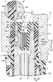
- FIG. 2 is an enlarged view of part 2 of FIG.
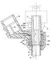
- FIG. 3 is an explanatory diagram of a cutting process during the manufacturing process of the fuel injection valve.
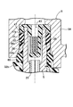
- FIG. 4 is a longitudinal sectional view of a main part of the fuel injection valve according to the second embodiment of the present invention.
- FIG. 5 is a longitudinal sectional view of a main part of a fuel injection valve according to the third embodiment of the present invention.
- hird embodiment shows an electromagnetic fuel injection valve according to a first embodiment of the present invention attached to an engine.
- FIG. 2 is an enlarged view of part 2 of FIG.
- FIG. 3 is an explanatory diagram of a cutting process during the manufacturing process of the fuel injection valve.
- FIG. 4 is a longitudinal sectional view of a main part of the fuel injection valve according to the second embodiment of the present invention.
- FIG. 5 is a longitudinal sectional view of a main
- Electromagnetic fuel injection valve V ... Valve assembly Y ... Valve housing axis 2 ... Valve housing 3 ... Valve seat member 4 ... ... Magnetic cylinder 4a ... Inner circumferential surface 5 of magnetic cylinder ... Fixed core 5a ... Attraction surface 6 ... Nonmagnetic cylinder 12 ... Movable core 14 ... Valve body 26 ... Fuel inlet cylinder 26a ... Large diameter portion 26b of fuel inlet cylinder ... Small diameter portion 26c of fuel inlet cylinder ... Annular shoulder 30 of fuel inlet cylinder ... ..Coil 32b ... coating layer (secondary coating layer) 38 ... collar 38a ... collar collar 38b ... collar rear end surface 43 ... fuel filter 47 ... mounting flange 47a ... mounting flange front end surface 50 ... ⁇ Seal groove 51... Seal member (O-ring) 54... Fuel supply cap
- FIG. 1 a valve housing 2 of an electromagnetic fuel injection valve (hereinafter simply referred to as a fuel injection valve) I for an engine is fitted to a cylindrical valve seat member 3 and a rear end portion of the valve seat member 3.
- a fuel injection valve electromagnetic fuel injection valve
- the valve seat member 3 includes a valve hole 7 that opens to a front end surface thereof, a conical valve seat 8 that is continuous with the inner end of the valve hole 7, and a cylindrical guide hole 9 that is continuous with a large diameter portion of the valve seat 8. And.
- a steel plate injector plate 10 having a plurality of fuel injection holes 11 communicating with the valve hole 7 is welded to the front end surface of the valve seat member 3 in a liquid-tight manner.
- a portion that does not fit with the fixed core 5 remains at the front end portion of the nonmagnetic cylindrical body 6, and the valve assembly V is accommodated in the valve housing 2 extending from the portion to the valve seat member 3.
- the valve assembly V includes a spherical valve body 14 that can slide in the guide hole 9 so as to open and close the valve hole 7 in cooperation with the valve seat 8, and a flange portion that is coupled to the valve body 14 by welding.
- the movable core 12 is slidably fitted to the inner peripheral surface 4a of the magnetic cylindrical body 4, and the suction surface 5a at the front end of the fixed core 5 is formed. It is opposed to.
- a plurality of flat surfaces that allow the passage of fuel are formed around the spherical valve body 14.
- the valve assembly V is provided with a vertical hole 19 starting from the rear end surface of the movable core 12 and ending at the middle portion of the flange portion 13, and a horizontal hole 20 that opens the vertical hole 19 to the outer peripheral surface of the flange portion 13.
- An annular spring seat 24 facing rearward is formed in the middle of the vertical hole 19.
- the eaves fixed core 5 has a vertical hole 21 that allows the hollow portion 26 d of the fuel inlet cylinder 26 to communicate with the front end surface of the fixed core 5.
- the vertical hole 21 has a smaller diameter than the hollow portion 26 d of the fuel inlet cylinder 26 and communicates with the vertical hole 19 of the movable core 12.
- a pipe-like retainer 23 is press-fitted into the vertical hole 21 of the fixed core 5, and a valve that urges the movable core 12 toward the valve closing side of the valve body 14 between the retainer 23 and the spring seat 24.
- the spring 22 is contracted.
- the set load of the valve spring 22 is adjusted by the depth of fitting of the retainer 23 into the vertical hole 21.
- a ring-shaped stopper member 37 made of a non-magnetic material that slightly protrudes from the rear end surface is embedded in the movable core 12.
- the stopper member 37 has a predetermined gap between the opposed end surfaces of the fixed core 5 and the movable core 12 by contacting the front end surface of the fixed core 5 when the fixed and movable cores 5 and 12 are attracted to each other. It will be left.
- a coil assembly 28 is fitted to the outer periphery of the soot valve housing 2 so as to correspond to the fixed core 5 and the movable core 12.
- the coil assembly 28 includes a bobbin 29 fitted to the outer peripheral surface from the rear end portion of the magnetic cylindrical body 4 to the fixed core 5, and a coil 30 wound around the bobbin 29.
- the proximal end portion of the coupler terminal 33 protruding to one side of the rear end portion is held at the rear end portion, and the terminal of the coil 30 is connected to the coupler terminal 33.
- the coil assembly 28 is molded with a synthetic resin primary coating layer 32a covering the outer periphery of the coil 30 so as to embed the coil 30 therein.
- a coupler 34 that receives and holds the coupler terminal 33 and protrudes to one side of the coil assembly 28 is integrally formed with the primary coating layer 32a.
- Both ends of a magnetic coil housing 31 that houses the coil assembly 28 are welded to the outer peripheral surfaces of the magnetic cylindrical body 4 and the fixed core 5, thereby magnetically connecting the magnetic cylindrical body 4 and the fixed core 5. .
- the fuel inlet cylinder 26 includes a large-diameter portion 26a connected to the fixed core 5 with the same diameter, and a small-diameter portion 26b connected to the large-diameter portion 26a via a rearward annular shoulder portion 26c. Is done.
- the annular shoulder portion 26 c is formed at right angles to the axis Y of the valve housing 2.
- an annular relief groove 35 having an inner surface continuous with the annular shoulder portion 26c is formed on the outer peripheral surface of the small diameter portion 26b.
- the annular shoulder portion 26c and the relief groove 35 are processed by the same cutting tool B (see FIG. 3).
- a press-fit guide portion 36a, a taper portion 36b, and a press-fit portion 36c are sequentially formed on the outer peripheral surface of the large-diameter portion 26a from the rear side, and the press-fit guide portion 36a is formed to have a slightly smaller diameter than the press-fit portion 36c.
- 36b smoothly connects between the press-fitting guide part 36a and the press-fitting part 36c.
- a collar 38 made of synthetic resin separate from the primary coating layer 32a is press-fitted to the outer peripheral surface of the front portion of the fuel inlet cylinder 26 while being guided by the press-fitting guide portion 36a and the tapered portion 36b.
- annular flange portion 38a that abuts on the annular shoulder portion 26c is formed so as to define the press-fitting depth of the collar 38 into the large diameter portion 26a. The inner peripheral edge is received in the escape groove 35.
- the length of the collar 38 is set so that a gap g is opened between the collar 38 and the rear end of the second coating layer 32b when the collar 38 is press-fitted to the fuel inlet cylinder 26.
- the collar 38 is given a color according to the use of the fuel injection valve I to which the collar 38 is attached.
- a small flange 40 is formed at the rear end of the small-diameter portion 26b so as to protrude to the outer peripheral side.
- the small flange 40 has a radial projecting amount smaller than the radial projecting amount of the annular shoulder 26c.
- the front end surface 40 a is formed at right angles to the axis Y of the valve housing 2.
- an annular relief groove 41 having an inner surface continuous with the front end surface 40a is formed on the outer periphery of the small diameter portion 26b. The front end face 40a and the annular groove 41 are processed by the same cutting tool.
- a fuel filter 43 is attached to the inlet of the fuel inlet cylinder 26.
- the fuel filter 43 includes a synthetic resin-made bottomed cylindrical filter body 44, a filter net 46 stretched in a plurality of window holes 45 opened in the peripheral wall of the filter body 44, and a rear end of the filter body 44.
- the filter main body 44 is press-fitted into the inner peripheral surface of the inlet of the fuel inlet tube 26.
- the attachment flange 47 is formed with an annular fitting recess 48 into which the rear end portion of the fuel inlet cylinder 26 is fitted.
- the inner surface of the fitting recess 48 is formed on the front end surface 40 a of the small flange 40.
- An annular locking protrusion 49 that is elastically engaged is formed.
- a tapered surface 40b is formed in the rear half of the outer peripheral surface of the small flange 40, and thereby the insertion of the small flange 40 into the fitting recess 48 is induced.
- annular seal groove 50 is defined by the rear end surface 38b of the collar 38, the front end surface 47a of the mounting flange 47 facing the collar 38, and the outer peripheral surface of the small diameter portion 26b exposed between them.
- An O-ring 51 is attached to the seal groove 50.
- a seal member 52 that is in close contact with the front end surface of the secondary coating layer 32b is attached to the outer periphery of the magnetic cylindrical body 4.
- This fuel injection valve I is attached to the engine as follows. That is, as shown in FIG. 1, the intake pipe E including the throttle body of the engine is provided with a mounting hole 53 on one side wall on the downstream side, and an annular recess 53a is formed at the outer end opening of the mounting hole 53. The The front end portion of the fuel injection valve I is fitted into the mounting hole 53 so as to push the seal member 52 into the annular recess 53a, and the rear end portion of the fuel injection valve I is held by a synthetic resin holding member R.
- the front end portion of the fuel injection valve I is fitted into the mounting hole 53 so as to push the seal member 52 into the annular recess 53a, and the rear end portion of the fuel injection valve I is held by a synthetic resin holding member R.
- the holding member R includes a fuel supply cap 54, a support arm 55 protruding from one side of the fuel supply cap 54, and a fuel joint 56 protruding from the other side of the fuel supply cap 54 and communicating with the inside thereof.
- the fuel supply cap 54 is fitted to the outer periphery of the fuel inlet cylinder 26 while the O-ring 51 is compressed on the inner peripheral surface thereof, and the support arm 55 is fitted to a predetermined portion of the intake pipe E. It is fixed to the formed mounting boss 57 with a bolt 58.
- the fuel joint 56 is connected to a fuel conduit 59 that guides fuel discharged from a fuel pump (not shown).
- a tapered surface 54 a that guides insertion of the O-ring 51 is formed at the inlet of the fuel supply cap 54.
- the fuel injection valve I attached to the intake pipe E is supplied with fuel pumped from a fuel pump (not shown) from the fuel supply cap 54 to the fuel inlet cylinder 26, and is filtered by the fuel filter 43.
- the inside is filled.
- the valve assembly V In a state where the coil coil 30 is demagnetized, the valve assembly V is pressed forward by the biasing force of the valve spring 22, and the valve body 14 is seated on the valve seat 8.
- the magnetic flux generated by the coil 30 sequentially travels through the coil housing 31, the magnetic cylindrical body 4, the movable core 12, and the fixed core 5, and the movable core 12 is attracted by the magnetic force generated between the cores 5 and 12. Is attracted to the fixed core 5 against the set load of the valve spring 22 and the valve body 14 is separated from the valve seat 8, so that the valve hole 7 is opened and the high-pressure fuel in the valve seat member 3 is removed from the valve hole 7.
- the fuel is injected from the fuel injection hole 11 of the injector plate 10 toward the upstream side in the intake pipe E.
- the large size of the fuel inlet cylinder 26 immediately after the secondary coating layer 32b is molded into the valve housing 2 and before the collar 38 is press-fitted is held by the rotary chuck C of the lathe, and the inner peripheral surface 4a of the magnetic cylindrical body 4 and the suction surface 5a of the fixed core 5 are cut and finished using the cutting tool B. Therefore, the influence of the distortion of the inner peripheral surface 4a of the magnetic cylindrical body 4 and the suction surface 5a of the fixed core 5 due to the molding of the secondary coating layer 32b can be eliminated, and the fuel injection characteristics of the fuel injection valve I can always be stabilized.
- the collar 38 is press-fitted and fixed to the outer peripheral surface of the fuel inlet cylinder 26, the collar 38 is firmly fixed to the fuel inlet cylinder 26. It is possible to prevent the 38 fuel inlet cylinders 26 from falling off.
- the press-fitting depth of the collar 38 into the outer periphery of the fuel inlet cylinder 26 can be restricted by simple contact between the annular shoulder 26c of the fuel inlet cylinder 26 and the annular flange 38a of the collar 38. Can contribute to simplification.
- annular shoulder portion 26c of the fuel inlet tube 26 is formed at right angles to the axis Y of the valve housing 2, and an annular relief groove 35 connected to the inner peripheral end of the annular shoulder portion 26c is formed on the small diameter of the fuel inlet tube 26. Since the annular shoulder portion 26c and the relief groove 35 are formed on the outer periphery of the fuel inlet cylinder 26 by the same cutting tool B, the roundness that exists at the tip of the cutting tool B is somewhat present. The entire annular shoulder 26c can be surely formed at right angles to the axis Y of the valve housing 2 without being affected by the fact that the escape groove 35 receives the inner peripheral edge of the annular flange 38a. , The contact between the annular shoulder portion 26c and the annular collar portion 38a of the collar 38 can be performed with high accuracy.
- the tapered surface 54a of the inlet of the fuel supply cap 54 is provided between the opposed end surfaces of the collar 38 and the secondary coating layer 32b. Except for the point that the second O-ring 60 that is in close contact with the second embodiment is mounted, the configuration is the same as that of the previous embodiment. Therefore, in FIG. A duplicate description is omitted.
- the cooperation of the O-ring 51 of the seal groove 50 and the second O-ring 60 can prevent foreign matter such as dust and rainwater from entering the fuel supply cap 54.
- the second O-ring 60 can clamp the fuel injection valve I along the axial direction in cooperation with the seal member 52 on the outer periphery of the magnetic cylinder 4 and prevent vibration thereof.
- FIG. 5 a third embodiment of the present invention shown in FIG. 5 will be described.
- a taper surface 54 a at the rear end surface of the secondary coating layer 32 b and the inlet of the fuel supply cap 54 is formed on the outer periphery of the collar 38. Except for the point that the second O-ring 60 that is in close contact with the first embodiment is mounted, the configuration is the same as that of the previous embodiment. Therefore, in FIG. A duplicate description is omitted.
Landscapes
- Engineering & Computer Science (AREA)
- Chemical & Material Sciences (AREA)
- Combustion & Propulsion (AREA)
- Mechanical Engineering (AREA)
- General Engineering & Computer Science (AREA)
- Physics & Mathematics (AREA)
- Electromagnetism (AREA)
- Manufacturing & Machinery (AREA)
- Fuel-Injection Apparatus (AREA)
Abstract
Description
V・・・・・弁組立体
Y・・・・・弁ハウジングの軸線
2・・・・・弁ハウジング
3・・・・・弁座部材
4・・・・・磁性円筒体
4a・・・・磁性円筒体の内周面
5・・・・・固定コア
5a・・・・吸引面
6・・・・・非磁性円筒体
12・・・・可動コア
14・・・・弁体
26・・・・燃料入口筒
26a・・・燃料入口筒の大径部
26b・・・燃料入口筒の小径部
26c・・・燃料入口筒の環状肩部
30・・・・コイル
32b・・・被覆層(2次被覆層)
38・・・・カラー
38a・・・カラーの環状鉤部
38b・・・カラーの後端面
43・・・・燃料フィルタ
47・・・・取り付けフランジ
47a・・・取り付けフランジの前端面
50・・・・シール溝
51・・・・シール部材(Oリング)
54・・・・燃料供給キャップ
Claims (8)
- 燃料噴射弁(I)の前端から後端に向けて,弁座部材(3),磁性円筒体(4),非磁性円筒体(6),固定コア(5)及び燃料入口筒(26)を順次連ねてなり内部を燃料流路とする弁ハウジング(2)と,この弁ハウジング(2)の外周に配設されるコイル(30)と,このコイル(30)を収容して前記磁性円筒体(4)及び固定コア(5)間を磁気的に接続するコイルハウジング(31)と,このコイルハウジング(31)を埋封するよう弁ハウジング(2)の外周に形成される合成樹脂製の被覆層(32b)と,前記磁性円筒体(4)の内周面(4a)に摺動自在に嵌合されて前記固定コア(5)の前端の吸引面(5a)に対置される可動コア(12)を有し,前記固定コア(5)の励起により開弁作動して前記弁座部材(3)の弁孔(7)から燃料を噴射させる弁組立体(V)と,前記燃料入口筒(26)の入口に装着される燃料フィルタ(43)とを備え,前記燃料入口筒(26)の後端部外周に環状のシール溝(50)を設け,このシール溝(50)には,前記燃料入口筒(26)の外周に嵌装される燃料供給キャップ(54)の内周面に密接するシール部材(51)を装着してなる電磁式燃料噴射弁において,
前記燃料入口筒(26)の外周面に前記被覆層(32b)とは別体の合成樹脂製のカラー(38)を嵌装し,このカラー(38)の後端面(38b)と,前記燃料入口筒(26)の後端部に嵌合して取り付けられる前記燃料フィルタ(43)の取り付けフランジ(47)の前端面(47a)とで,その間の前記燃料入口筒(26)外周に前記シール溝(50)を画成したことを特徴とする電磁式燃料噴射弁。 - 請求項1記載の電磁式燃料噴射弁において,
前記カラー(38)を前記燃料入口筒(26)の外周面に圧入嵌合したことを特徴とする電磁式燃料噴射弁。 - 請求項2記載の電磁式燃料噴射弁において,
前記燃料入口筒(26)を,前記固定コア(5)に連なる大径部(26a)と,この大径部(26a)の後端に環状肩部(26c)を介して連なる小径部(26b)とで構成する一方,前記カラー(38)に,これの前記大径部(26a)への圧入嵌合深さを規定すべく前記環状肩部(26c)に当接する環状鉤部(38a)を形成したことを特徴とする電磁式燃料噴射弁。 - 請求項3記載の電磁式燃料噴射弁において,
前記環状肩部(26c)を前記弁ハウジング(2)の軸線(Y)に直角に形成すると共に,この環状肩部(26c)の内周端に連なる環状の逃げ溝(35)を前記小径部(26b)の外周に削成し,この逃げ溝(35)に前記環状鉤部(38a)の内周端縁を受容するようにしたことを特徴とする電磁式燃料噴射弁。 - 請求項3記載の電磁式燃料噴射弁において,
前記カラー(38)及び前記被覆層(32b)の対向端面間に間隔を開けたことを特徴とする電磁式燃料噴射弁。 - 請求項1~4の何れかに記載の電磁式燃料噴射弁において,
前記カラー(38)及び前記被覆層(32b)の対向端面間に,前記燃料供給キャップ(54)の内周面に密接する第2のシール部材(60)を装着したことを特徴とする電磁式燃料噴射弁。 - 請求項1~5の何れかに記載の電磁式燃料噴射弁において,
前記カラー(38)の外周に,前記被覆層(32b)の後端面及び前記燃料供給キャップ(54)の内周面に密接する第2のシール部材(60)を装着したことを特徴とする電磁式燃料噴射弁。 - 請求項1~7の何れかに記載の電磁式燃料噴射弁において,
前記カラー(38)には,燃料噴射弁(I)の用途を識別する色彩を付与することを特徴とする電磁式燃料噴射弁。
Priority Applications (2)
| Application Number | Priority Date | Filing Date | Title |
|---|---|---|---|
| BR112012023000-0A BR112012023000B1 (pt) | 2010-03-26 | 2010-11-18 | válvula de injeção de combustível eletromagnêtica |
| CN201080065702.8A CN102822497B (zh) | 2010-03-26 | 2010-11-18 | 电磁式燃料喷射阀 |
Applications Claiming Priority (2)
| Application Number | Priority Date | Filing Date | Title |
|---|---|---|---|
| JP2010071658A JP5394298B2 (ja) | 2010-03-26 | 2010-03-26 | 電磁式燃料噴射弁 |
| JP2010-071658 | 2010-03-26 |
Publications (1)
| Publication Number | Publication Date |
|---|---|
| WO2011118082A1 true WO2011118082A1 (ja) | 2011-09-29 |
Family
ID=44672666
Family Applications (1)
| Application Number | Title | Priority Date | Filing Date |
|---|---|---|---|
| PCT/JP2010/070567 Ceased WO2011118082A1 (ja) | 2010-03-26 | 2010-11-18 | 電磁式燃料噴射弁 |
Country Status (4)
| Country | Link |
|---|---|
| JP (1) | JP5394298B2 (ja) |
| CN (1) | CN102822497B (ja) |
| BR (1) | BR112012023000B1 (ja) |
| WO (1) | WO2011118082A1 (ja) |
Families Citing this family (1)
| Publication number | Priority date | Publication date | Assignee | Title |
|---|---|---|---|---|
| JP6065311B2 (ja) * | 2012-11-02 | 2017-01-25 | 株式会社ケーヒン | 電磁式燃料噴射弁 |
Citations (6)
| Publication number | Priority date | Publication date | Assignee | Title |
|---|---|---|---|---|
| JPH0382874U (ja) * | 1989-12-12 | 1991-08-23 | ||
| JPH06323221A (ja) * | 1993-05-13 | 1994-11-22 | Nippon Injector Kk | 燃料噴射弁 |
| JP2001115929A (ja) * | 1999-10-19 | 2001-04-27 | Keihin Corp | 電磁式燃料噴射弁の取付け位置決め構造 |
| WO2001055585A1 (en) * | 2000-01-26 | 2001-08-02 | Hitachi, Ltd. | Electromagnetic fuel injector |
| JP2005009421A (ja) * | 2003-06-19 | 2005-01-13 | Hitachi Ltd | 電磁式燃料噴射弁 |
| JP2007239561A (ja) * | 2006-03-07 | 2007-09-20 | Denso Corp | 燃料噴射弁 |
Family Cites Families (6)
| Publication number | Priority date | Publication date | Assignee | Title |
|---|---|---|---|---|
| IT214896Z2 (it) * | 1988-10-28 | 1990-07-04 | Weber Srl | Dispositivo di alimentazione di un motore a combustione interna provvisto di un elemento filtrante di tipo perfezionato |
| US5335863A (en) * | 1993-05-03 | 1994-08-09 | Siemens Automotive L.P. | Filter cartridge mounting for a top-feed fuel injector |
| US6419282B1 (en) * | 2000-08-09 | 2002-07-16 | Siemens Automotive Corporation | Compliant zero evaporative fuel connection |
| JP2002081356A (ja) * | 2000-09-06 | 2002-03-22 | Keihin Corp | 電磁式燃料噴射弁 |
| JP3734702B2 (ja) * | 2000-10-17 | 2006-01-11 | 株式会社日立製作所 | 電磁式燃料噴射弁 |
| DE10130205A1 (de) * | 2001-06-22 | 2003-01-02 | Bosch Gmbh Robert | Brennstoffeinspritzventil |
-
2010
- 2010-03-26 JP JP2010071658A patent/JP5394298B2/ja active Active
- 2010-11-18 WO PCT/JP2010/070567 patent/WO2011118082A1/ja not_active Ceased
- 2010-11-18 BR BR112012023000-0A patent/BR112012023000B1/pt active IP Right Grant
- 2010-11-18 CN CN201080065702.8A patent/CN102822497B/zh active Active
Patent Citations (6)
| Publication number | Priority date | Publication date | Assignee | Title |
|---|---|---|---|---|
| JPH0382874U (ja) * | 1989-12-12 | 1991-08-23 | ||
| JPH06323221A (ja) * | 1993-05-13 | 1994-11-22 | Nippon Injector Kk | 燃料噴射弁 |
| JP2001115929A (ja) * | 1999-10-19 | 2001-04-27 | Keihin Corp | 電磁式燃料噴射弁の取付け位置決め構造 |
| WO2001055585A1 (en) * | 2000-01-26 | 2001-08-02 | Hitachi, Ltd. | Electromagnetic fuel injector |
| JP2005009421A (ja) * | 2003-06-19 | 2005-01-13 | Hitachi Ltd | 電磁式燃料噴射弁 |
| JP2007239561A (ja) * | 2006-03-07 | 2007-09-20 | Denso Corp | 燃料噴射弁 |
Also Published As
| Publication number | Publication date |
|---|---|
| BR112012023000A2 (pt) | 2017-01-24 |
| JP5394298B2 (ja) | 2014-01-22 |
| CN102822497A (zh) | 2012-12-12 |
| JP2011202613A (ja) | 2011-10-13 |
| CN102822497B (zh) | 2016-01-27 |
| BR112012023000B1 (pt) | 2020-12-29 |
Similar Documents
| Publication | Publication Date | Title |
|---|---|---|
| US7770812B2 (en) | Fuel injector and method for its installation | |
| WO2011121839A1 (ja) | 電磁式燃料噴射弁及びその製造方法 | |
| US20020063174A1 (en) | Fuel injection valve | |
| JP2002130082A (ja) | 燃料噴射弁 | |
| JP5014090B2 (ja) | 電磁式燃料噴射弁及びその製造方法 | |
| US20030230649A1 (en) | Electromagnetic fuel injection valve | |
| EP2461013B1 (en) | Electromagnetic fuel injection valve | |
| JP4453745B2 (ja) | 燃料噴射弁 | |
| CN100419251C (zh) | 电磁式燃料喷射阀及其制造方法 | |
| JP5394298B2 (ja) | 電磁式燃料噴射弁 | |
| US9359987B2 (en) | Injector | |
| JP2010031674A (ja) | 電磁式燃料噴射弁 | |
| US20060249601A1 (en) | Fuel injection valve | |
| JP2002081356A (ja) | 電磁式燃料噴射弁 | |
| JP5558293B2 (ja) | 燃料噴射弁の支持装置 | |
| JP5254131B2 (ja) | 電磁式燃料噴射弁 | |
| JP4669852B2 (ja) | 電磁式燃料噴射弁 | |
| JP4767795B2 (ja) | 電磁式燃料噴射弁 | |
| JPH11230006A (ja) | 燃料噴射弁 | |
| JP3819864B2 (ja) | 電磁式燃料噴射弁 | |
| CN117321300A (zh) | 电磁式燃料喷射阀 | |
| JP2004060534A (ja) | 燃料噴射弁のoリング取り付け構造 | |
| CN109642527B (zh) | 燃料喷射阀 | |
| JP3837300B2 (ja) | 燃料噴射弁におけるエアアシストキャップの位置決め構造 | |
| US20060192163A1 (en) | Fluid injection valve |
Legal Events
| Date | Code | Title | Description |
|---|---|---|---|
| WWE | Wipo information: entry into national phase |
Ref document number: 201080065702.8 Country of ref document: CN |
|
| 121 | Ep: the epo has been informed by wipo that ep was designated in this application |
Ref document number: 10848474 Country of ref document: EP Kind code of ref document: A1 |
|
| NENP | Non-entry into the national phase |
Ref country code: DE |
|
| WWE | Wipo information: entry into national phase |
Ref document number: 1201004871 Country of ref document: TH |
|
| WWE | Wipo information: entry into national phase |
Ref document number: 8956/CHENP/2012 Country of ref document: IN |
|
| 122 | Ep: pct application non-entry in european phase |
Ref document number: 10848474 Country of ref document: EP Kind code of ref document: A1 |
|
| REG | Reference to national code |
Ref country code: BR Ref legal event code: B01A Ref document number: 112012023000 Country of ref document: BR |
|
| ENP | Entry into the national phase |
Ref document number: 112012023000 Country of ref document: BR Kind code of ref document: A2 Effective date: 20120912 |