WO2011111794A1 - 微粒子分散液製造方法および微粒子分散液製造装置 - Google Patents
微粒子分散液製造方法および微粒子分散液製造装置 Download PDFInfo
- Publication number
- WO2011111794A1 WO2011111794A1 PCT/JP2011/055698 JP2011055698W WO2011111794A1 WO 2011111794 A1 WO2011111794 A1 WO 2011111794A1 JP 2011055698 W JP2011055698 W JP 2011055698W WO 2011111794 A1 WO2011111794 A1 WO 2011111794A1
- Authority
- WO
- WIPO (PCT)
- Prior art keywords
- solvent
- particle dispersion
- fine particle
- container
- solid
- Prior art date
- Legal status (The legal status is an assumption and is not a legal conclusion. Google has not performed a legal analysis and makes no representation as to the accuracy of the status listed.)
- Ceased
Links
Images




Classifications
-
- B—PERFORMING OPERATIONS; TRANSPORTING
- B01—PHYSICAL OR CHEMICAL PROCESSES OR APPARATUS IN GENERAL
- B01J—CHEMICAL OR PHYSICAL PROCESSES, e.g. CATALYSIS OR COLLOID CHEMISTRY; THEIR RELEVANT APPARATUS
- B01J19/00—Chemical, physical or physico-chemical processes in general; Their relevant apparatus
- B01J19/08—Processes employing the direct application of electric or wave energy, or particle radiation; Apparatus therefor
- B01J19/12—Processes employing the direct application of electric or wave energy, or particle radiation; Apparatus therefor employing electromagnetic waves
- B01J19/121—Coherent waves, e.g. laser beams
-
- A—HUMAN NECESSITIES
- A61—MEDICAL OR VETERINARY SCIENCE; HYGIENE
- A61K—PREPARATIONS FOR MEDICAL, DENTAL OR TOILETRY PURPOSES
- A61K9/00—Medicinal preparations characterised by special physical form
- A61K9/48—Preparations in capsules, e.g. of gelatin, of chocolate
- A61K9/50—Microcapsules having a gas, liquid or semi-solid filling; Solid microparticles or pellets surrounded by a distinct coating layer, e.g. coated microspheres, coated drug crystals
- A61K9/51—Nanocapsules; Nanoparticles
- A61K9/5107—Excipients; Inactive ingredients
- A61K9/513—Organic macromolecular compounds; Dendrimers
- A61K9/5138—Organic macromolecular compounds; Dendrimers obtained by reactions only involving carbon-to-carbon unsaturated bonds, e.g. polyvinyl pyrrolidone, poly(meth)acrylates
-
- B—PERFORMING OPERATIONS; TRANSPORTING
- B01—PHYSICAL OR CHEMICAL PROCESSES OR APPARATUS IN GENERAL
- B01J—CHEMICAL OR PHYSICAL PROCESSES, e.g. CATALYSIS OR COLLOID CHEMISTRY; THEIR RELEVANT APPARATUS
- B01J19/00—Chemical, physical or physico-chemical processes in general; Their relevant apparatus
- B01J19/008—Processes for carrying out reactions under cavitation conditions
-
- B—PERFORMING OPERATIONS; TRANSPORTING
- B01—PHYSICAL OR CHEMICAL PROCESSES OR APPARATUS IN GENERAL
- B01J—CHEMICAL OR PHYSICAL PROCESSES, e.g. CATALYSIS OR COLLOID CHEMISTRY; THEIR RELEVANT APPARATUS
- B01J19/00—Chemical, physical or physico-chemical processes in general; Their relevant apparatus
- B01J19/08—Processes employing the direct application of electric or wave energy, or particle radiation; Apparatus therefor
- B01J19/12—Processes employing the direct application of electric or wave energy, or particle radiation; Apparatus therefor employing electromagnetic waves
- B01J19/122—Incoherent waves
- B01J19/128—Infrared light
-
- B—PERFORMING OPERATIONS; TRANSPORTING
- B02—CRUSHING, PULVERISING, OR DISINTEGRATING; PREPARATORY TREATMENT OF GRAIN FOR MILLING
- B02C—CRUSHING, PULVERISING, OR DISINTEGRATING IN GENERAL; MILLING GRAIN
- B02C19/00—Other disintegrating devices or methods
- B02C19/18—Use of auxiliary physical effects, e.g. ultrasonic waves or irradiation, for disintegrating
-
- B—PERFORMING OPERATIONS; TRANSPORTING
- B02—CRUSHING, PULVERISING, OR DISINTEGRATING; PREPARATORY TREATMENT OF GRAIN FOR MILLING
- B02C—CRUSHING, PULVERISING, OR DISINTEGRATING IN GENERAL; MILLING GRAIN
- B02C19/00—Other disintegrating devices or methods
- B02C19/18—Use of auxiliary physical effects, e.g. ultrasonic waves or irradiation, for disintegrating
- B02C2019/183—Crushing by discharge of high electrical energy
-
- B—PERFORMING OPERATIONS; TRANSPORTING
- B02—CRUSHING, PULVERISING, OR DISINTEGRATING; PREPARATORY TREATMENT OF GRAIN FOR MILLING
- B02C—CRUSHING, PULVERISING, OR DISINTEGRATING IN GENERAL; MILLING GRAIN
- B02C23/00—Auxiliary methods or auxiliary devices or accessories specially adapted for crushing or disintegrating not provided for in preceding groups or not specially adapted to apparatus covered by a single preceding group
- B02C23/06—Selection or use of additives to aid disintegrating
Definitions
- the present invention relates to a method and an apparatus for producing a fine particle dispersion.
- the fine particle preparation is attracting attention as a solution that can solve these problems.
- the fine particle formulation is obtained by stably dispersing insoluble water particles having poorly soluble drug particles having a size of micrometer or less.
- By using the fine particle preparation it is possible to increase the absorption rate and amount of the drug in vivo. In addition, it can be expected to reduce the variation in the amount of absorption within and between patients and to increase the effective utilization rate with respect to the dose.
- Patent Documents 1 and 2 disclose the invention of a method for producing such a fine particle formulation.
- the solid matter that is not dissolved in the solvent of the liquid to be treated is finely divided to produce fine particles of the solid matter, so that the solid matter has a wavelength longer than the absorption band of the solid matter.
- an unintended impurity may be generated by causing a photochemical reaction via an electronic excited state in the solid material that has absorbed the irradiated light.
- the microparticles to be produced are pharmaceuticals, it is important that unintentional impurity generation is avoided.
- the present invention has been made to solve the above problems, and provides a fine particle dispersion production method and a fine particle dispersion production apparatus that can easily achieve both suppression of impurity generation and high efficiency of fine particle production.
- the purpose is to do.
- the method for producing a fine particle dispersion according to the present invention includes (1) an injection step of injecting a solvent into a container containing solids, and bringing the solvent into contact with the solids in the container; After the step, selectively irradiate the solvent with pulse light selectively among the solid matter and the solvent in the container, and repeat the expansion and contraction of the solvent at the irradiated location to generate a pressure wave in the solvent, And an irradiation step of producing a fine particle dispersion in which the solid matter is microparticulated by applying the pressure wave to the solid matter and the fine particles are dispersed in a solvent.
- the fine particle dispersion manufacturing method includes (3) a dissolving step of dissolving a poorly soluble drug and a dispersion stabilizer in a volatile organic solvent, and (4) an organic solvent contained in the dissolving liquid obtained in this dissolving step. And a fixing step of fixing the solid material obtained by removing the organic solvent to the inner wall of the container, and it is preferable to perform an injection step and an irradiation step after the fixing step. is there.
- one container may be used throughout the dissolution process, the fixing process, the injection process, and the irradiation process.
- the container used in the process until obtaining the solid matter and the container used in the steps after fixing the solid matter may be separate from each other.
- An apparatus for producing a fine particle dispersion according to the present invention includes (1) a container in which a solid is contained and a solvent is injected to bring the solvent into contact with the solid, and (2) the solid and the solvent in the container. And a light source that selectively and repeatedly irradiates the solvent with pulsed light. Furthermore, the fine particle dispersion manufacturing apparatus of the present invention repeatedly irradiates the solvent with a pulsed light from a light source, thereby repeating the expansion and contraction of the solvent at the irradiated portion to generate a pressure wave in the solvent. It is characterized by producing a fine particle dispersion in which a solid is made into fine particles by applying a pressure wave to the solid, and the fine particles are dispersed in a solvent.
- the container is a solid obtained by dissolving a poorly soluble drug and a dispersion stabilizer in a volatile organic solvent and evaporating and removing the organic solvent contained in the solution. It is preferable that the object is fixed to the inner wall and the solvent is injected into the inside. In this case, after this, solvent injection into the container and pulsed light irradiation to the solvent are performed.
- FIG. 1 is a configuration diagram of a fine particle dispersion producing apparatus 10 of the present embodiment.
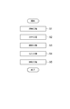
- FIG. 2 is a flowchart for explaining the fine particle dispersion manufacturing method of the present embodiment.
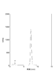
- FIG. 3 is an HPLC chart of the fine particle dispersion obtained in Example 1.
- FIG. 4 is a graph showing the particle size distribution of the fine particles contained in the fine particle dispersion obtained in Example 1.
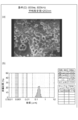
- FIG. 5 is an electron micrograph of the fine particles contained in the fine particle dispersion obtained in Example 1.
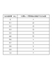
- FIG. 6 is a chart summarizing the success or failure of micronization when the amount of water as a solvent injected into the well is set to each value in Example 1.
- FIG. 7 is a table summarizing the output conditions of the pulse laser beam in the second embodiment.
- FIG. 8 is a view showing an electron micrograph and particle size distribution of fine particles contained in the fine particle dispersion obtained in Example 2.
- FIG. 9 is a diagram showing an electron micrograph and particle size distribution of fine particles contained in the fine particle dispersion obtained in Example 2.
- 10 is a view showing an electron micrograph and particle size distribution of fine particles contained in the fine particle dispersion obtained in Example 2.
- FIG. 11 is a diagram showing an electron micrograph and particle size distribution of fine particles contained in the fine particle dispersion obtained in Example 2.
- FIG. 12 is a table summarizing the success or failure of microparticulation when the amount of water as the solvent injected into the well is set to each value under the condition (A) of Example 2.
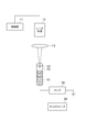
- FIG. 13 is a configuration diagram of the pressure wave evaluation apparatus used in the third embodiment.
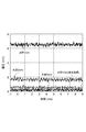
- FIG. 14 is a graph showing the waveform of the digital oscilloscope obtained in Example 3.
- FIG. 15 is a graph showing the waveform of the digital oscilloscope obtained in Example 3.
- FIG. 1 is a configuration diagram of a fine particle dispersion producing apparatus 10 of the present embodiment.
- the fine particle dispersion manufacturing apparatus 10 of the present embodiment includes a control unit 11, a light source 12, an irradiation optical system 13, and a container 14.
- the solid material 1 in the container 14 is made into fine particles, and the fine particles are dispersed in the solvent 2. A fine particle dispersion is produced.
- the container 14 can be in a state in which the solid material 1 is contained therein and the solvent 2 is injected, and the solvent 2 is in contact with the solid material 1.
- a multiwell plate in which a plurality of wells are formed on a common plate. In this case, each well is used as the container 14.
- the material of the container 14 is arbitrary, and may be, for example, polypropylene.
- the light source 12 repeatedly outputs pulsed light.
- the light source 12 is preferably a pulsed laser light source.
- the wavelength of the pulse laser beam output from the light source 12 is preferably included in a wavelength region where the absorption coefficient of the solvent 2 injected into the container 14 is large.
- the light source 12 may be a solid laser light source, a semiconductor laser light source, or a quantum cascade laser light source in the latter case.
- a semiconductor laser array in which a plurality of semiconductor laser light sources are arranged in parallel is preferably used.
- the irradiation optical system 13 guides the pulse laser beam output from the light source 12 and selectively irradiates the solvent 2 with the pulse laser beam selectively among the solid 1 and the solvent 2 in the container 14.
- the irradiation optical system 13 is preferably a condensing optical system for condensing and irradiating pulsed laser light into the solvent 2.
- the irradiation optical system 13 has a scanning unit that scans the irradiation position of the pulse laser beam.
- a light source 12 that outputs pulsed laser light having a wavelength with a large absorption coefficient of the solvent 2 is used.
- the solvent 2 may be irradiated with the pulse laser beam from above by the irradiation optical system 13. In this case, most of the energy of the pulse laser beam is absorbed by the solvent 2, and the energy of the pulse laser beam reaching the solid material 1 becomes small, and the photolysis and thermal decomposition of the solid material 1 are suppressed.
- the control unit 11 controls the operation of the light source 12. Specifically, the control unit 11 controls the start and stop of the repeated output of the pulse laser light from the light source 12, and controls the power, pulse width, and repetition frequency of the pulse laser light output from the light source 12. I do. When the output wavelength of the light source 12 is variable, it is also preferable that the control unit 11 controls the output wavelength of the light source 12.
- the fine particle dispersion manufacturing apparatus 10 may further include a temperature adjusting unit including a thermostatic bath, a thermometer, and temperature adjusting means.
- a temperature adjusting unit including a thermostatic bath, a thermometer, and temperature adjusting means.
- the temperature of the container 14 accommodated in the thermostat and the liquid to be processed contained in the container 14 can be kept constant by feedback control using a thermometer and temperature control means.
- a portion through which the pulse laser beam output from the light source 12 passes is a transparent window.
- FIG. 2 is a flowchart for explaining the fine particle dispersion manufacturing method of the present embodiment.
- the multi-well plate is used as the container 14, and the dissolution step S1, the dispensing step S2, the fixing step S3, the injection step S4, and the irradiation step S5 are sequentially performed.
- the dissolution step S1 the dispensing step S2, the fixing step S3, the injection step S4, and the irradiation step S5 are sequentially performed.
- a liquid in which fine particles containing a poorly soluble drug and a dispersion stabilizer are dispersed in water is produced.
- the poorly soluble drug and the dispersion stabilizer are dissolved in the volatile organic solvent in the container 14.
- the poorly soluble drug is a drug that hardly dissolves in water
- the solubility is not particularly limited, but it is desirable that the solubility at a temperature of 25 ° C. is 50 ⁇ g / mL or less.
- poorly soluble drugs examples include cyclosporine, tacrolimus, nifedipine, nicardipine hydrochloride, phenytoin, digitoxin, diazepam, nitrofurantoin, benoxaprofen, griseofulvin, sulfathiazole, piroxicam, carbamazepine, phenacetin, tolbutamide, theophylline, griseofulvin,
- over-the-counter drugs such as adrenocortical hormones such as ramphenicol, paclitaxel, camptothecin, cisplatin, daunorubicin, methotrexate, mitomycin C, docetaxel, vincristine, amphotericin B, nystatin, and clobetasone butyrate, and other new drug candidates under development Can be mentioned.
- the dispersion stabilizer is preferably a polymer or a surfactant.
- the high molecular weight polymer is desirably a substance that has high water solubility and is easily soluble in various organic solvents.
- High molecular weight polymers include, for example, cellulose derivatives such as hydroxypropylmethylcellulose, methylcellulose, hydroxypropylcellulose, hydroxypropylmethylcellulose phthalate, hydroxypropylmethylcellulose acetate succinate, sodium carboxymethylcellulose, cellulose acetate phthalate, agar, gelatin, sodium alginate, polyvinyl Examples include pyrrolidone, aminoalkyl methacrylate copolymer, methacrylic acid copolymer, carboxyvinyl polymer, polyvinyl alcohol, and polyethylene glycol.
- the surfactant is desirably low-toxic, and examples thereof include sodium lauryl sulfate, cholic acid, deoxycholic acid, and polyoxyethylene sorbitan fatty acid este
- organic solvent examples include alcohols such as methanol, ethanol and propanol, acetone, acetonitrile, methyl acetate, ethyl acetate and diethyl ether, and more preferable are alcohols such as methanol, ethanol and propanol.
- the solution obtained in the dissolving step S1 is evenly dispensed into each well of the multiwell plate as the container 14.
- the organic solvent contained in the solution dispensed in each container 14 in the dispensing step S2 is removed by evaporation, and the pellet-like solid 1 is obtained by removing the organic solvent.
- the solid 1 is fixed to the bottom of the container 14.
- the injection step S4 following the fixing step S3 water as the solvent 2 is injected into the container 14.
- the solid material 1 fixed to the bottom of the container 14 is immersed in the solvent 2 (see FIG. 1).
- the pulse laser beam output from the light source 12 and passed through the irradiation optical system 13 is irradiated onto the solvent 2 in the container 14 from above, and most of the energy is absorbed by the solvent 2. Is done.
- this irradiation step S5 by irradiating the solvent 2 with pulsed laser light, the light energy absorbed in the solvent at the irradiated location is converted into thermal energy, and rapid thermal expansion / evaporation of the solvent occurs at the irradiated location.
- the solvent at the irradiation site is cooled by the surrounding solvent, and the shrinkage / condensation of the solvent occurs at the irradiation site. That is, when the solvent 2 is repeatedly irradiated with the pulsed laser light, the solvent 2 is repeatedly expanded and contracted at the irradiated portion, and a pressure wave is generated in the solvent 2.
- This pressure wave propagates through the solvent 2 to reach the surface of the solid 1 and acts on the solid 1 to make the solid 1 fine. In this way, a fine particle dispersion in which the fine particles are dispersed in the solvent 2 is produced.
- the fine particles contain a poorly soluble drug and a dispersion stabilizer.
- fine particles containing a poorly soluble drug and a dispersion stabilizer are produced. Further, the fine particle dispersion is freeze-dried to produce freeze-dried fine particles. Furthermore, a preparation for oral administration containing a fine particle dispersion, fine particles or freeze-dried fine particles is manufactured, and for injection administration containing a fine particle dispersion, a dispersion obtained by resuspending fine particles or freeze-dried fine particles in water A formulation is manufactured.
- the solid laser 1 and the solvent 2 are selectively irradiated with the pulsed laser light selectively.
- a pressure wave resulting from repeated expansion and contraction of the solvent 2 at the irradiation site is generated in the solvent 2, and the pressure wave acts on the solid 1, thereby solidifying the solid 1. That is, light energy or heat energy does not act directly on the solid material 1.
- the degree of freedom in selecting the wavelength and intensity of the pulsed laser beam is high, and it becomes easy to both suppress the generation of impurities from the solid material 1 and increase the efficiency of the generation of fine particles.
- the fine particle dispersion production apparatus 10 of the present embodiment or the fine particle dispersion production method of the present embodiment can be suitably used when the fine particles to be produced are pharmaceutical products.
- the fine particle dispersion manufacturing apparatus 10 of the present embodiment can use a semiconductor laser light source as the light source 12, it can be reduced in size and power consumption, and the output intensity and repetition frequency of the pulsed laser beam can be reduced. Since it is easy to control, micronization can be performed under various conditions. Furthermore, since the fine particle dispersion manufacturing apparatus 10 of the present embodiment can use a multiwell plate as the container 14 and a semiconductor laser array as the light source 12, it is easy to improve the processing efficiency of the fine particle formation.
- Example 1 Next, more specific examples of the fine particle dispersion manufacturing apparatus or the fine particle dispersion manufacturing method of the present embodiment will be described.
- Example 1 a fine particle dispersion of an immunosuppressant Cyclosporin A (hereinafter referred to as “CsA”), which is a poorly soluble drug, was prepared.
- the pulsed laser beam output from the quantum cascade laser light source was repeatedly irradiated from above the well onto the water layer in the well.
- the wavelength of this pulse laser beam was 8.6 ⁇ m
- the average output was 120 mW
- the peak output was 10 W
- the pulse width was 120 ns
- the repetition frequency was 100 kHz.
- a pulse laser beam was condensed near the surface of the water layer using a near-infrared lens having a focal length of 50 mm as an irradiation optical system.
- the spot shape of the condensing part was an ellipse having a major axis of 2 mm and a minor axis of 1 mm.
- the laser fluence was 76 ⁇ J / cm 2 .
- the condensing part became clouded 10 seconds after the start of irradiation.
- a fine particle dispersion of CsA was obtained. In this example, all the above operations were performed at room temperature (20 ° C.).
- the amount of CsA and the purity contained in the obtained dispersion were quantified by measuring the absorbance at a wavelength of 210 nm using high performance liquid chromatography (hereinafter referred to as “HPLC”). Measurement was performed at a flow rate of 1 mL / min and a temperature of 60 ° C. using ODS-C18 (manufactured by Tosoh Corporation) as a separation carrier and acetonitrile-isopropanol-water (55:15:30) as a mobile phase. The obtained dispersion was diluted 10-fold with methanol-water (1: 1) to completely dissolve the fine particles, and then used for measurement. As a sample, a CsA bulk powder dissolved in methanol-water (1: 1) so as to be 1 mg / mL was used.
- HPLC high performance liquid chromatography
- FIG. 3 is an HPLC chart of the fine particle dispersion obtained in Example 1.
- CsA eluted at about 7.5 min.
- the amount of CsA in the fine particle dispersion calculated based on the peak area obtained by measuring the standard product was 9.6 mg / mL.
- a fine particle dispersion having a sufficiently high concentration as compared with the solubility in water (23 ⁇ g / mL) could be prepared. Further, on the HPLC chart, no increase in the contaminant peak due to laser light irradiation was observed.
- FIG. 4 is a graph showing the particle size distribution of the fine particles contained in the fine particle dispersion obtained in Example 1.
- UPA-UT151 manufactured by Nikkiso Co., Ltd.
- the presence of fine particles was observed in the particle size range of 40 nm to 400 nm, and the average particle size was 109 nm. It is considered to be a uniform fine particle dispersion having a uniform particle size.
- FIG. 5 is an electron micrograph of the fine particles contained in the fine particle dispersion obtained in Example 1.
- a scanning electron microscope S4200 manufactured by Hitachi, Ltd.
- the dispersion liquid was placed on a polycarbonate filter having a pore diameter of 200 nm and air-dried overnight, and then photographing was performed.
- the black holes indicate the pores of the polycarbonate filter
- the white objects indicate the fine particles.
- the shape of the fine particles was spherical, and many fine particles having a particle diameter of about 100 nm were observed. This is consistent with the particle size distribution data of FIG. 4 and is considered to be a uniform fine particle group.
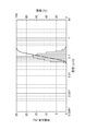
- FIG. 6 is a chart summarizing the success or failure of microparticulation when the amount of water as the solvent injected into the well in Example 1 is each value.
- the amount of water as a solvent to be injected into the well containing the solid matter was changed from 0 mL to 1 mL, and pulsed laser light irradiation was performed in each case. Other manufacturing conditions are the same as above.
- the vicinity of the solid condensing part was instantly whitened, but no white turbidity occurred even when water was injected after the end of irradiation.
- the injection amount of water was from 0.1 mL to 0.6 mL, white turbidity occurred within 1 minute after the start of laser beam irradiation.
- the amount of water injected was 0.7 mL or more, white turbidity did not occur even when irradiated with laser light for 1 minute or longer.
- the absorption coefficient of water used as the solvent 2 in Example 1 is about 453 cm ⁇ 1 at the laser beam wavelength of 8.6 ⁇ m. According to the calculation, when a laser beam having a wavelength of 8.6 ⁇ m is incident on a water layer having a thickness of 0.1 mm, the transmitted light is attenuated to 10 ⁇ 2 with respect to the incident light. When a laser beam having a wavelength of 8.6 ⁇ m is incident on a 1 mm thick water layer, the transmitted light attenuates to 10 ⁇ 20 with respect to the incident light.
- Example 1 when water with a thickness of 1 mm exists on a solid material and a laser beam with a wavelength of 8.6 ⁇ m is irradiated from above, most of the energy of the laser beam is The energy of the laser light that is absorbed by water and reaches the solid matter becomes small, and the photolysis and thermal decomposition of the solid matter are suppressed.
- Example 2 Next, Example 2 will be described.
- a quantum cascade laser light source that outputs pulsed laser light having a wavelength of 5.8 ⁇ m was used.
- FIG. 7 is a table summarizing the output conditions of the pulse laser beam in the second embodiment. Irradiation was performed for 10 minutes under the four output conditions (A), (B), (C), and (D) shown in FIG. Other production conditions, particle size distribution measurement conditions, and microscope observation conditions are the same as in Example 1.
- FIGS. 8 to 11 are views showing electron micrographs and particle size distributions of the fine particles contained in the fine particle dispersion obtained in Example 2, respectively.
- the average particle sizes are 70 nm, 154 nm, 140 nm, and 202 nm, respectively.
- the shape of the fine particles was all spherical. Further, from the result of the particle size distribution, it was considered that the average particle size of the generated fine particles increases as the average output of the laser increases.
- FIG. 12 shows water as a solvent to be injected into the well under the condition (A) of Example 2 (that is, the condition of irradiating pulse laser light having a wavelength of 5.8 ⁇ m, a pulse width of 100 ns, a repetition frequency of 100 kHz, and an average output of 31 mW).
- 6 is a chart summarizing the success or failure of atomization when the amount is each value.
- the amount of water as a solvent to be injected into the well containing the solid matter was changed from 0 mL to 1 mL, and pulsed laser light irradiation was performed in each case. Other manufacturing conditions are the same as above.
- Example 3 Next, Example 3 will be described.
- the pressure wave evaluation apparatus shown in FIG. 13 was used to actually confirm the generation and propagation of the pressure wave in water.
- a rubber tube 53 was wound around a commercially available piezoelectric microphone 51 so as to be in close contact, and the microphone 51 was fixed in the vertical direction.
- the rubber tube 53 was filled with water 52, and pulsed laser light was condensed near the surface of the water layer.
- the electromotive force obtained by piezoelectric conversion in the piezoelectric microphone 51 is amplified 25 times by an amplifier 55 (dual channel programmable filter 3625, manufactured by NF Circuit Design Block Co., Ltd.), and then an oscilloscope 56 (digital oscilloscope TDS784A, manufactured by Nippon Tektronix Co., Ltd.). ).
- FIG. 14 is obtained when the thickness of the water layer filled in the rubber tube is 1 mm, 2 mm, or 5 mm and irradiation with pulsed laser light having a wavelength of 5.8 ⁇ m, a pulse width of 100 ns, a repetition frequency of 100 kHz, and an average output of 31 mW.
- It is a graph which shows the waveform of a digital oscilloscope. This graph shows the relationship between the water layer thickness and the electromotive force when the laser output is fixed at 100 ns and 100 kHz. As can be seen from these waveforms, the electromotive force decreased as the thickness of the water layer was increased, and almost no electromotive force was generated at 5 mm. Further, when a light shielding material was inserted into the laser optical path when the thickness of the water layer was 1 mm, no electromotive force was generated.
- FIG. 15 is a graph showing the waveform of a digital oscilloscope obtained when the thickness of the water layer in the rubber tube is 1 mm and pulsed laser light having a wavelength of 5.8 ⁇ m is irradiated under various output conditions. .
- This graph shows the relationship between the laser output and the electromotive force when the thickness of the water layer is fixed at 1 mm. As can be seen from these waveforms, the electromotive force increased as the average output of the laser increased.
- the absorption coefficient of water used as the solvent 2 in Example 2 and Example 3 is about 715 cm ⁇ 1 at the laser beam wavelength of 5.8 ⁇ m. According to the calculation, when a laser beam having a wavelength of 5.8 ⁇ m is incident on a water layer having a thickness of 0.1 mm, the transmitted light is attenuated to 10 ⁇ 3 with respect to the incident light. When laser light having a wavelength of 5.8 ⁇ m is incident on a 1 mm thick water layer, the transmitted light attenuates to 10 ⁇ 30 with respect to the incident light.
- Example 2 and Example 3 above when water with a thickness of 1 mm exists and laser light with a wavelength of 5.8 ⁇ m is irradiated from above, most of the energy of the laser light is absorbed by water. As a result, the energy of the laser beam reaching the solid matter becomes small. The energy absorbed by the water is consumed for the generation of pressure waves. Pressure waves propagate with attenuation. If the water layer is made thick, energy that can be used to make solids fine particles will not reach, so fine particles will not be generated.
- the fine particle dispersion manufacturing method and the fine particle dispersion manufacturing apparatus according to the present invention are not limited to the above-described embodiments and examples, and various modifications are possible.
- the present invention can be used as a fine particle dispersion production method and a production apparatus that can easily suppress both impurity generation and increase the efficiency of fine particle production.
Landscapes
- Chemical & Material Sciences (AREA)
- Health & Medical Sciences (AREA)
- Physics & Mathematics (AREA)
- Engineering & Computer Science (AREA)
- General Health & Medical Sciences (AREA)
- Toxicology (AREA)
- Organic Chemistry (AREA)
- Chemical Kinetics & Catalysis (AREA)
- Optics & Photonics (AREA)
- Electromagnetism (AREA)
- Bioinformatics & Cheminformatics (AREA)
- Epidemiology (AREA)
- Nanotechnology (AREA)
- Medicinal Chemistry (AREA)
- Pharmacology & Pharmacy (AREA)
- Biomedical Technology (AREA)
- Life Sciences & Earth Sciences (AREA)
- Animal Behavior & Ethology (AREA)
- Public Health (AREA)
- Veterinary Medicine (AREA)
- Food Science & Technology (AREA)
- Physical Or Chemical Processes And Apparatus (AREA)
- Medicinal Preparation (AREA)
- Colloid Chemistry (AREA)
Abstract
Description
次に、本実施形態の微粒子分散液製造装置または微粒子分散液製造方法のより具体的な実施例について説明する。
次に、実施例2について説明する。実施例2では、波長5.8μmのパルスレーザ光を出力する量子カスケードレーザ光源を用いた。図7は、実施例2におけるパルスレーザ光の出力条件を纏めた図表である。図7に示す(A)、(B)、(C)及び(D)の4種の出力条件により、10分間照射を行った。その他の製造条件、粒子径分布測定条件および顕微鏡観察条件は実施例1と同様である。
次に、実施例3について説明する。実施例3では、水中での圧力波の発生および伝播を実際に確認するため、図13に示す圧力波評価装置を使用した。市販の圧電マイクロフォン51の周りに、密着するようにゴムチューブ53を巻き、マイクロフォン51を鉛直方向に固定した。ゴムチューブ53内に水52を満たし、水層表面付近でパルスレーザ光を集光した。圧電マイクロフォン51内の圧電変換により得られる起電力は、アンプ55(デュアルチャネルプログラマブルフィルタ3625、株式会社エヌエフ回路設計ブロック製)により25倍に増幅後、オシロスコープ56(デジタルオシロスコープTDS784A、日本テクトロニクス株式会社製)に入力することで評価した。
Claims (4)
- 固形物が容れられた容器内に溶媒を注入して、前記容器内において前記固形物に前記溶媒が接触した状態とする注入工程と、
この注入工程の後に、前記容器内の前記固形物および前記溶媒のうち選択的に前記溶媒に対してパルス光を繰り返し照射して、当該照射箇所において前記溶媒の膨張および収縮を繰り返させて圧力波を前記溶媒中に発生させ、この圧力波を前記固形物に作用させることにより前記固形物を微粒子化して、当該微粒子が前記溶媒中に分散された微粒子分散液を製造する照射工程と、
を備えることを特徴とする微粒子分散液製造方法。 - 難溶性薬物および分散安定化剤を揮発性の有機溶媒に溶解させる溶解工程と、
この溶解工程において得られた溶解液に含まれる前記有機溶媒を蒸発除去し、当該有機溶媒除去により得られる固形物を容器の内壁に固定する固定工程と、
を更に備え、
前記固定工程の後に前記注入工程および前記照射工程を行う、
ことを特徴とする請求項1に記載の微粒子分散液製造方法。 - 内部に固形物が容れられるとともに溶媒が注入されて、前記固形物に前記溶媒が接触した状態とする容器と、
前記容器内の前記固形物および前記溶媒のうち選択的に前記溶媒に対してパルス光を繰り返し照射する光源と、
を備え、
前記光源から前記溶媒に対してパルス光を繰り返し照射することにより、当該照射箇所において前記溶媒の膨張および収縮を繰り返させて圧力波を前記溶媒中に発生させ、この圧力波を前記固形物に作用させることにより前記固形物を微粒子化して、当該微粒子が前記溶媒中に分散された微粒子分散液を製造する、
ことを特徴とする微粒子分散液製造装置。 - 前記容器は、内部において難溶性薬物および分散安定化剤が揮発性の有機溶媒に溶解され、当該溶解液に含まれる前記有機溶媒が蒸発除去されることにより得られる固形物が内壁に固定され、内部に前記溶媒が注入される、
ことを特徴とする請求項3に記載の微粒子分散液製造装置。
Priority Applications (3)
| Application Number | Priority Date | Filing Date | Title |
|---|---|---|---|
| JP2012504526A JP5677409B2 (ja) | 2010-03-11 | 2011-03-10 | 微粒子分散液製造方法および微粒子分散液製造装置 |
| US13/583,361 US9168504B2 (en) | 2010-03-11 | 2011-03-10 | Fine-particle dispersion liquid manufacturing method and fine-particle dispersion liquid manufacturing apparatus |
| CN201180013508.XA CN102791368B (zh) | 2010-03-11 | 2011-03-10 | 微粒子分散液制造方法和微粒子分散液制造装置 |
Applications Claiming Priority (2)
| Application Number | Priority Date | Filing Date | Title |
|---|---|---|---|
| JP2010054618 | 2010-03-11 | ||
| JP2010-054618 | 2010-03-11 |
Publications (1)
| Publication Number | Publication Date |
|---|---|
| WO2011111794A1 true WO2011111794A1 (ja) | 2011-09-15 |
Family
ID=44563592
Family Applications (1)
| Application Number | Title | Priority Date | Filing Date |
|---|---|---|---|
| PCT/JP2011/055698 Ceased WO2011111794A1 (ja) | 2010-03-11 | 2011-03-10 | 微粒子分散液製造方法および微粒子分散液製造装置 |
Country Status (4)
| Country | Link |
|---|---|
| US (1) | US9168504B2 (ja) |
| JP (1) | JP5677409B2 (ja) |
| CN (1) | CN102791368B (ja) |
| WO (1) | WO2011111794A1 (ja) |
Cited By (1)
| Publication number | Priority date | Publication date | Assignee | Title |
|---|---|---|---|---|
| JP2013129903A (ja) * | 2011-11-21 | 2013-07-04 | Toyota Central R&D Labs Inc | 無機ナノ粒子の製造方法及び無機ナノ粒子分散液 |
Families Citing this family (1)
| Publication number | Priority date | Publication date | Assignee | Title |
|---|---|---|---|---|
| CN108731961A (zh) * | 2018-05-21 | 2018-11-02 | 苏州阿洛斯环境发生器有限公司 | 一种人工尘发生方法以及系统 |
Citations (5)
| Publication number | Priority date | Publication date | Assignee | Title |
|---|---|---|---|---|
| JP2001113159A (ja) * | 1999-10-14 | 2001-04-24 | Dainippon Ink & Chem Inc | 有機化合物の微粒子の製造方法 |
| JP2005008524A (ja) * | 2003-06-16 | 2005-01-13 | Hamamatsu Photonics Kk | 微粒子、その製造方法及び製造装置、並びに注射剤及びその製造方法 |
| WO2007132852A1 (ja) * | 2006-05-15 | 2007-11-22 | Ebara Corporation | 難水溶性医薬 |
| JP2009079007A (ja) * | 2007-09-26 | 2009-04-16 | Hamamatsu Photonics Kk | 微粒子分散液製造方法および微粒子分散液製造装置 |
| JP2009084249A (ja) * | 2007-10-02 | 2009-04-23 | Hamamatsu Photonics Kk | パクリタキセル固体組成物、パクリタキセル微粒子、パクリタキセル微粒子分散液、および、これらの製造方法 |
Family Cites Families (7)
| Publication number | Priority date | Publication date | Assignee | Title |
|---|---|---|---|---|
| US5145684A (en) * | 1991-01-25 | 1992-09-08 | Sterling Drug Inc. | Surface modified drug nanoparticles |
| WO2004080586A1 (ja) * | 2003-03-07 | 2004-09-23 | Hamamatsu Photonics K.K. | 微粒子、その製造方法及び製造装置、並びに注射剤及びその製造方法 |
| JP4545690B2 (ja) * | 2003-11-20 | 2010-09-15 | 浜松ホトニクス株式会社 | 微粒子の製造方法、及び製造装置 |
| JP4482322B2 (ja) * | 2003-12-18 | 2010-06-16 | 浜松ホトニクス株式会社 | 微粒子の製造方法、及び製造装置 |
| US8663702B2 (en) * | 2006-04-07 | 2014-03-04 | Hamamatsu Photonics K.K. | Microparticles, microparticle dispersion and method and apparatus for producing the same |
| JP2007306950A (ja) * | 2006-05-15 | 2007-11-29 | Osaka Univ | 薬効成分ナノ粒子分散液の製造方法 |
| US8445019B2 (en) * | 2007-09-26 | 2013-05-21 | Hamamatsu Photonics K.K. | Microparticle dispersion liquid manufacturing method and microparticle dispersion liquid manufacturing apparatus |
-
2011
- 2011-03-10 CN CN201180013508.XA patent/CN102791368B/zh not_active Expired - Fee Related
- 2011-03-10 JP JP2012504526A patent/JP5677409B2/ja not_active Expired - Fee Related
- 2011-03-10 WO PCT/JP2011/055698 patent/WO2011111794A1/ja not_active Ceased
- 2011-03-10 US US13/583,361 patent/US9168504B2/en not_active Expired - Fee Related
Patent Citations (5)
| Publication number | Priority date | Publication date | Assignee | Title |
|---|---|---|---|---|
| JP2001113159A (ja) * | 1999-10-14 | 2001-04-24 | Dainippon Ink & Chem Inc | 有機化合物の微粒子の製造方法 |
| JP2005008524A (ja) * | 2003-06-16 | 2005-01-13 | Hamamatsu Photonics Kk | 微粒子、その製造方法及び製造装置、並びに注射剤及びその製造方法 |
| WO2007132852A1 (ja) * | 2006-05-15 | 2007-11-22 | Ebara Corporation | 難水溶性医薬 |
| JP2009079007A (ja) * | 2007-09-26 | 2009-04-16 | Hamamatsu Photonics Kk | 微粒子分散液製造方法および微粒子分散液製造装置 |
| JP2009084249A (ja) * | 2007-10-02 | 2009-04-23 | Hamamatsu Photonics Kk | パクリタキセル固体組成物、パクリタキセル微粒子、パクリタキセル微粒子分散液、および、これらの製造方法 |
Cited By (1)
| Publication number | Priority date | Publication date | Assignee | Title |
|---|---|---|---|---|
| JP2013129903A (ja) * | 2011-11-21 | 2013-07-04 | Toyota Central R&D Labs Inc | 無機ナノ粒子の製造方法及び無機ナノ粒子分散液 |
Also Published As
| Publication number | Publication date |
|---|---|
| US20130056565A1 (en) | 2013-03-07 |
| CN102791368B (zh) | 2015-11-25 |
| CN102791368A (zh) | 2012-11-21 |
| US9168504B2 (en) | 2015-10-27 |
| JP5677409B2 (ja) | 2015-02-25 |
| JPWO2011111794A1 (ja) | 2013-06-27 |
Similar Documents
| Publication | Publication Date | Title |
|---|---|---|
| Sheeran et al. | Phase-transition thresholds and vaporization phenomena for ultrasound phase-change nanoemulsions assessed via high-speed optical microscopy | |
| Shah et al. | Application of Plackett–Burman screening design for preparing glibenclamide nanoparticles for dissolution enhancement | |
| Krogstad et al. | Nanoparticle-releasing nanofiber composites for enhanced in vivo vaginal retention | |
| JP5095609B2 (ja) | 微粒子分散液製造方法 | |
| JP5677409B2 (ja) | 微粒子分散液製造方法および微粒子分散液製造装置 | |
| Choi et al. | Enhanced oral bioavailability of Rivaroxaban-Loaded microspheres by optimizing the polymer and surfactant based on molecular interaction mechanisms | |
| JP5149585B2 (ja) | 微粒子分散液製造方法 | |
| US20110306564A1 (en) | Solid composition, microparticles, microparticle dispersion liquid, and manufacturing methods for these | |
| Baek et al. | Comparison of solid self-nanoemulsifying systems and surface-coated microspheres: improving oral bioavailability of niclosamide | |
| Liu et al. | Rational design of keratin nanoparticles utilizing diverse hair protein fractions for controlled drug release | |
| US8563044B2 (en) | Microparticle dispersion liquid manufacturing method and microparticle dispersion liquid manufacturing apparatus | |
| JP5236235B2 (ja) | 微粒子分散液製造方法および微粒子分散液製造装置 | |
| Tian et al. | Controlling Release of Integral Lipid Nanoparticles Based on Osmotic Pump Technology: Tian et al. | |
| JP2005125258A (ja) | 微粒子、微粒子の製造方法、及び製造装置 | |
| JP5161528B2 (ja) | パクリタキセル微粒子、パクリタキセル微粒子分散液、および、これらの製造方法 | |
| Sanklecha | A systematic review on solid dispersion: Enhancing the solubility of poorly soluble drug | |
| JP2024176646A (ja) | 微粒子製造装置及び微粒子製造方法 | |
| Patil et al. | Solubility as well as Bioavailability Enhancement Techniques | |
| Mujtaba et al. | Development of hot melt extruded co-formulated artesunate and amodiaquine-soluplus® solid dispersion system in fixed-dose form: amorphous state characterization and pharmacokinetic evaluation | |
| Hasan et al. | SMEDDS tablet: Compatability of solid SMEDDS using various pharmaceutical tablet excipients | |
| JP4287727B2 (ja) | 微粒子の製造方法、及び製造装置 | |
| JP4398182B2 (ja) | 微粒子の製造方法、並びに注射剤の製造方法 | |
| NOOTHI et al. | Preparation and Evaluation of Simvastatin Nanosponges. | |
| Ding et al. | Preparation and pharmacokinetic study of mebendazole complex with HP-beta-cyclodextrin | |
| Birari et al. | Development and Characterization of Solid Dispersion System for Solubility Enhancement of Fenofibrate |
Legal Events
| Date | Code | Title | Description |
|---|---|---|---|
| WWE | Wipo information: entry into national phase |
Ref document number: 201180013508.X Country of ref document: CN |
|
| 121 | Ep: the epo has been informed by wipo that ep was designated in this application |
Ref document number: 11753452 Country of ref document: EP Kind code of ref document: A1 |
|
| WWE | Wipo information: entry into national phase |
Ref document number: 2012504526 Country of ref document: JP |
|
| NENP | Non-entry into the national phase |
Ref country code: DE |
|
| WWE | Wipo information: entry into national phase |
Ref document number: 13583361 Country of ref document: US |
|
| 122 | Ep: pct application non-entry in european phase |
Ref document number: 11753452 Country of ref document: EP Kind code of ref document: A1 |