WO2011111701A1 - Dispositif de surveillance de l'environnement d'un véhicule - Google Patents
Dispositif de surveillance de l'environnement d'un véhicule Download PDFInfo
- Publication number
- WO2011111701A1 WO2011111701A1 PCT/JP2011/055371 JP2011055371W WO2011111701A1 WO 2011111701 A1 WO2011111701 A1 WO 2011111701A1 JP 2011055371 W JP2011055371 W JP 2011055371W WO 2011111701 A1 WO2011111701 A1 WO 2011111701A1
- Authority
- WO
- WIPO (PCT)
- Prior art keywords
- image
- virtual screen
- vehicle
- unit
- road surface
- Prior art date
Links
- 238000012806 monitoring device Methods 0.000 title claims description 46
- 238000003384 imaging method Methods 0.000 claims abstract description 38
- 238000006243 chemical reaction Methods 0.000 claims description 149
- 238000001514 detection method Methods 0.000 claims description 38
- 238000009434 installation Methods 0.000 claims description 28
- 238000002834 transmittance Methods 0.000 claims description 27
- 238000012544 monitoring process Methods 0.000 claims description 19
- 239000000203 mixture Substances 0.000 claims description 15
- 230000015572 biosynthetic process Effects 0.000 claims description 12
- 238000003786 synthesis reaction Methods 0.000 claims description 12
- 230000005540 biological transmission Effects 0.000 claims description 3
- 230000003247 decreasing effect Effects 0.000 claims description 3
- 230000007423 decrease Effects 0.000 claims 1
- 238000004364 calculation method Methods 0.000 description 47
- 238000013500 data storage Methods 0.000 description 29
- 239000002131 composite material Substances 0.000 description 17
- 230000004913 activation Effects 0.000 description 15
- 238000005259 measurement Methods 0.000 description 9
- 238000000034 method Methods 0.000 description 8
- 238000010586 diagram Methods 0.000 description 5
- 230000002194 synthesizing effect Effects 0.000 description 5
- 230000000007 visual effect Effects 0.000 description 5
- 208000003443 Unconsciousness Diseases 0.000 description 2
- 230000009471 action Effects 0.000 description 2
- 238000013459 approach Methods 0.000 description 2
- 230000035699 permeability Effects 0.000 description 2
- 238000012545 processing Methods 0.000 description 2
- 230000000630 rising effect Effects 0.000 description 2
- 230000008859 change Effects 0.000 description 1
- 230000000694 effects Effects 0.000 description 1
- 239000004973 liquid crystal related substance Substances 0.000 description 1
- 230000003287 optical effect Effects 0.000 description 1
- 230000002093 peripheral effect Effects 0.000 description 1
- 238000013139 quantization Methods 0.000 description 1
- 230000009466 transformation Effects 0.000 description 1
- 238000000844 transformation Methods 0.000 description 1
Images


Classifications
-
- G—PHYSICS
- G08—SIGNALLING
- G08G—TRAFFIC CONTROL SYSTEMS
- G08G1/00—Traffic control systems for road vehicles
- G08G1/16—Anti-collision systems
-
- B—PERFORMING OPERATIONS; TRANSPORTING
- B60—VEHICLES IN GENERAL
- B60R—VEHICLES, VEHICLE FITTINGS, OR VEHICLE PARTS, NOT OTHERWISE PROVIDED FOR
- B60R1/00—Optical viewing arrangements; Real-time viewing arrangements for drivers or passengers using optical image capturing systems, e.g. cameras or video systems specially adapted for use in or on vehicles
- B60R1/20—Real-time viewing arrangements for drivers or passengers using optical image capturing systems, e.g. cameras or video systems specially adapted for use in or on vehicles
- B60R1/22—Real-time viewing arrangements for drivers or passengers using optical image capturing systems, e.g. cameras or video systems specially adapted for use in or on vehicles for viewing an area outside the vehicle, e.g. the exterior of the vehicle
- B60R1/23—Real-time viewing arrangements for drivers or passengers using optical image capturing systems, e.g. cameras or video systems specially adapted for use in or on vehicles for viewing an area outside the vehicle, e.g. the exterior of the vehicle with a predetermined field of view
- B60R1/27—Real-time viewing arrangements for drivers or passengers using optical image capturing systems, e.g. cameras or video systems specially adapted for use in or on vehicles for viewing an area outside the vehicle, e.g. the exterior of the vehicle with a predetermined field of view providing all-round vision, e.g. using omnidirectional cameras
-
- B—PERFORMING OPERATIONS; TRANSPORTING
- B60—VEHICLES IN GENERAL
- B60R—VEHICLES, VEHICLE FITTINGS, OR VEHICLE PARTS, NOT OTHERWISE PROVIDED FOR
- B60R1/00—Optical viewing arrangements; Real-time viewing arrangements for drivers or passengers using optical image capturing systems, e.g. cameras or video systems specially adapted for use in or on vehicles
- B60R1/20—Real-time viewing arrangements for drivers or passengers using optical image capturing systems, e.g. cameras or video systems specially adapted for use in or on vehicles
- B60R1/22—Real-time viewing arrangements for drivers or passengers using optical image capturing systems, e.g. cameras or video systems specially adapted for use in or on vehicles for viewing an area outside the vehicle, e.g. the exterior of the vehicle
- B60R1/28—Real-time viewing arrangements for drivers or passengers using optical image capturing systems, e.g. cameras or video systems specially adapted for use in or on vehicles for viewing an area outside the vehicle, e.g. the exterior of the vehicle with an adjustable field of view
-
- G—PHYSICS
- G06—COMPUTING; CALCULATING OR COUNTING
- G06T—IMAGE DATA PROCESSING OR GENERATION, IN GENERAL
- G06T3/00—Geometric image transformations in the plane of the image
- G06T3/40—Scaling of whole images or parts thereof, e.g. expanding or contracting
- G06T3/4038—Image mosaicing, e.g. composing plane images from plane sub-images
-
- G—PHYSICS
- G06—COMPUTING; CALCULATING OR COUNTING
- G06V—IMAGE OR VIDEO RECOGNITION OR UNDERSTANDING
- G06V20/00—Scenes; Scene-specific elements
- G06V20/50—Context or environment of the image
- G06V20/56—Context or environment of the image exterior to a vehicle by using sensors mounted on the vehicle
- G06V20/58—Recognition of moving objects or obstacles, e.g. vehicles or pedestrians; Recognition of traffic objects, e.g. traffic signs, traffic lights or roads
-
- G—PHYSICS
- G08—SIGNALLING
- G08G—TRAFFIC CONTROL SYSTEMS
- G08G1/00—Traffic control systems for road vehicles
- G08G1/16—Anti-collision systems
- G08G1/167—Driving aids for lane monitoring, lane changing, e.g. blind spot detection
-
- B—PERFORMING OPERATIONS; TRANSPORTING
- B60—VEHICLES IN GENERAL
- B60R—VEHICLES, VEHICLE FITTINGS, OR VEHICLE PARTS, NOT OTHERWISE PROVIDED FOR
- B60R2300/00—Details of viewing arrangements using cameras and displays, specially adapted for use in a vehicle
- B60R2300/10—Details of viewing arrangements using cameras and displays, specially adapted for use in a vehicle characterised by the type of camera system used
- B60R2300/105—Details of viewing arrangements using cameras and displays, specially adapted for use in a vehicle characterised by the type of camera system used using multiple cameras
-
- B—PERFORMING OPERATIONS; TRANSPORTING
- B60—VEHICLES IN GENERAL
- B60R—VEHICLES, VEHICLE FITTINGS, OR VEHICLE PARTS, NOT OTHERWISE PROVIDED FOR
- B60R2300/00—Details of viewing arrangements using cameras and displays, specially adapted for use in a vehicle
- B60R2300/20—Details of viewing arrangements using cameras and displays, specially adapted for use in a vehicle characterised by the type of display used
-
- B—PERFORMING OPERATIONS; TRANSPORTING
- B60—VEHICLES IN GENERAL
- B60R—VEHICLES, VEHICLE FITTINGS, OR VEHICLE PARTS, NOT OTHERWISE PROVIDED FOR
- B60R2300/00—Details of viewing arrangements using cameras and displays, specially adapted for use in a vehicle
- B60R2300/30—Details of viewing arrangements using cameras and displays, specially adapted for use in a vehicle characterised by the type of image processing
- B60R2300/307—Details of viewing arrangements using cameras and displays, specially adapted for use in a vehicle characterised by the type of image processing virtually distinguishing relevant parts of a scene from the background of the scene
- B60R2300/308—Details of viewing arrangements using cameras and displays, specially adapted for use in a vehicle characterised by the type of image processing virtually distinguishing relevant parts of a scene from the background of the scene by overlaying the real scene, e.g. through a head-up display on the windscreen
Definitions
- the present invention relates to a vehicle surrounding monitoring device that is installed in a vehicle and displays an image of the surroundings of the vehicle. More specifically, the present invention relates to a vehicle surrounding monitoring device that can accurately display the presence of an obstacle when there is an obstacle around the vehicle.
- Patent Document 1 when synthesizing overhead images, an invention has been proposed in which the position of the joint of the images is set based on the behavior of the vehicle.
- Patent Document 1 since an object having a height is projected and converted onto a road surface, the object having a height from the road surface is distorted in the image after conversion. There is a problem that a three-dimensional object becomes difficult to recognize.
- the present invention has been made in view of the above circumstances, and a vehicle surrounding monitoring device capable of accurately displaying a three-dimensional object having a height from a road surface without distortion even at a joint between images without causing a blind spot.
- the purpose is to provide.
- the vehicle periphery monitoring device is attached to the periphery of the vehicle, and the virtual screen installation unit is included in an overlapping region of a plurality of imaging units arranged so that a part of adjacent imaging ranges overlaps.
- a virtual screen extending in a perspective direction with respect to the vehicle is installed, and a virtual screen projection image generation unit generates a virtual screen projection image by projecting each image captured by the adjacent imaging unit onto the virtual screen.
- the first viewpoint conversion unit converts the virtual screen projection image into an image observed from a predetermined viewpoint position in a predetermined line-of-sight direction, and the image display unit displays the coordinate-converted image. .
- the first vehicle surrounding monitoring apparatus includes a plurality of photographing units installed in a vehicle with a part of an adjacent photographing range having an overlapping region so as to photograph the surroundings of the vehicle, Inside the overlapping area of the shooting range, each of each of the images shot by the virtual screen setting unit that sets a virtual screen extending in the perspective direction with respect to the vehicle and rising in the vertical direction from the road surface, and the adjacent shooting unit A half line extending from the position corresponding to each principal point of the photographing unit toward each pixel of the image photographed by the photographing unit intersects with the virtual screen.
- a virtual screen projection image generation unit stored at a position to be coordinated, and coordinate conversion of the image generated by the virtual screen projection image generation unit into an image observed from a predetermined viewpoint position toward a predetermined gaze direction
- a first viewpoint conversion unit for outputting Te characterized in that an image display unit which displays the image output from the first viewpoint conversion unit.
- the virtual screen installation unit is in the perspective direction with respect to the vehicle in the overlapping region of the shooting ranges of the adjacent shooting units.
- a virtual screen projection image generation unit projects a value corresponding to the gray value of each image captured by the imaging unit adjacent to the virtual screen to generate a virtual screen projection image,
- the image display unit By displaying the virtual screen projection image generated in this way by the image display unit, it is possible to accurately display a three-dimensional object having a height from the road surface without causing a blind spot even at the joint between the images. Can do.
- the second vehicle surrounding monitoring device includes a plurality of photographing units installed in a vehicle with a part of an adjacent photographing range having an overlapping region so as to photograph the surroundings of the vehicle, Inside the overlapping area of the shooting range, each of each of the images shot by the virtual screen setting unit that sets a virtual screen extending in the perspective direction with respect to the vehicle and rising in the vertical direction from the road surface, and the adjacent shooting unit A half line extending from the position corresponding to each principal point of the photographing unit toward each pixel of the image photographed by the photographing unit intersects with the virtual screen.
- the first viewpoint conversion unit to be operated, and the gray value stored in each pixel of each image photographed by the plurality of photographing units are photographed by the photographing unit from a position corresponding to each principal point of the photographing unit.
- a road projection image generation unit storing a half line extending toward each pixel of the image at a position intersecting the road surface; and an image generated by the road projection image generation unit from the predetermined viewpoint position,
- a second viewpoint conversion unit that converts and outputs an image observed in the direction of the line of sight, an image output from the first viewpoint conversion unit, and an image output from the second viewpoint conversion unit,
- An image composition unit that composes and outputs a single image and an image display unit that displays the image outputted from the image composition unit are provided.
- the virtual screen installation unit is in the perspective direction with respect to the vehicle in the overlapping region of the shooting ranges of the adjacent shooting units.
- a virtual screen projection image generator generates a virtual screen projection image by projecting a value corresponding to the gray value of each image captured by the imaging unit adjacent to the virtual screen onto the virtual screen.
- the road surface projection image generation unit generates a road surface projection image by projecting the gray value stored in each pixel of each image captured by the plurality of image capturing units onto the road surface, and the virtual screen projection image thus generated and
- the image is present not only at the boundary between adjacent shooting ranges but also around the vehicle. Also three-dimensional object can be accurately displayed.
- a three-dimensional object having a height from the road surface that is present at the joint of images taken by a plurality of photographing units installed around the vehicle is accurately displayed without distortion.
- the vehicle can be smoothly parked or turned back on the basis of the displayed image.
- FIG. 1 is a block diagram illustrating a schematic configuration of a vehicle surroundings monitoring apparatus according to a first embodiment of the present invention.
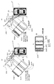
- A It is a left view of the vehicle in which Example 1 of this invention was installed.
- B It is a top view of the vehicle in which Example 1 of the present invention was installed.
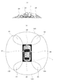
- FIG. 6 is a layout diagram of a surrounding environment virtually set.
- A It is a figure explaining a mode that the image image
- B) It is a figure explaining a mode that the image image
- C It is a figure which shows a 1st virtual screen projection image.
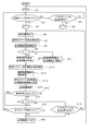
- Example 1 of this invention It is a flowchart explaining operation
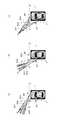
- A It is a figure explaining a mode that the image image
- B It is a figure explaining a mode that the image image
- C It is a figure explaining a mode that the image image
- (B) It is a figure which shows a synthetic
- (A) It is an example of the image displayed on the display monitor at the time of vehicle advance.
- (B) It is an example of the image displayed on the display monitor at the time of vehicle reverse. It is a figure which shows another display form of Example 1 of this invention.
- (A) It is a left view of the vehicle by which Example 2 of this invention was installed.
- (B) It is a top view of the vehicle by which Example 2 of this invention was installed. It is a flowchart explaining the operation
- (A) It is the layout of the surrounding environment of the vehicle set virtually.
- the present invention is applied to a vehicle surrounding monitoring device 2 capable of displaying images around a vehicle photographed by a plurality of cameras installed in the vehicle in a form that is easy for the driver to see. is there.
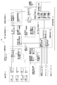
- FIG. 1 is a block diagram illustrating a configuration of a vehicle surrounding monitoring device 2 according to a first embodiment of the present invention.
- the vehicle surrounding monitoring device 2 according to the first embodiment is installed in a vehicle 1 (not shown), and an operation detection unit 10 that detects a start operation and an end operation of the vehicle surrounding monitoring device 2 by a driver.
- An operation switch 15 that is installed within the reach of the driver and that instructs activation and termination of the vehicle surroundings monitoring device 2, an imaging unit 20 that includes a plurality of cameras that capture images around the vehicle, Among the plurality of cameras constituting the unit 20, the virtual screen installation unit 30 that installs a virtual screen in the overlapping part of the shooting areas of adjacent cameras, and the virtual screen installed by the virtual screen installation unit 30, the adjacent camera
- a virtual screen projection image generation unit 40 that projects each captured image to generate a virtual screen projection image, and projects a captured image around the vehicle onto a road surface to project a road surface projection image.
- the first viewpoint that converts the virtual screen projection image generated by the road surface projection image generation unit 50 and the virtual screen projection image generation unit 40 that are generated from the predetermined virtual viewpoint into the image observed in the predetermined virtual line-of-sight direction.
- a conversion unit 60 a second viewpoint conversion unit 70 that converts the road projection image generated by the road projection image generation unit 50 into an image observed from the predetermined virtual viewpoint toward the predetermined virtual line-of-sight direction;
- the image synthesis unit 80 that synthesizes the virtual screen projection image converted by the one viewpoint conversion unit 60 and the road projection image converted by the second viewpoint conversion unit 70 into one image, and the image synthesis unit 80 synthesizes the image.
- an image display unit 90 for displaying an image.
- the operation detection unit 10 detects a start switch operation detection unit 11 that detects a driver's start switch operation, an end switch operation detection unit 12 that detects a driver's end switch operation, and a shift position of the vehicle. It consists of a shift position detector 13 and a vehicle speed detector 14 that detects the vehicle speed.
- the operation switch 15 includes an activation switch 16 for instructing activation of the vehicle surroundings monitoring device 2 and an end switch 18 for instructing termination of the vehicle surroundings monitoring device 2.
- the imaging unit 20 is installed around the vehicle as shown in FIG. 2, and the first camera 22, the second camera 24, the third camera 26, and the fourth camera are arranged so that adjacent imaging regions overlap each other.
- the third decoder 27 converts the output signal of the camera 26 into a digital signal by AD conversion
- the fourth decoder 29 converts the output signal of the fourth camera 28 into a digital signal by AD conversion.
- the virtual screen projection image generation unit 40 is created in advance based on the installation positions of the first camera 22 to the fourth camera 28 and the installation positions of the virtual screen in order to generate a virtual screen projection image.
- a first coordinate conversion data storage unit 44 storing the coordinate conversion data table, and a virtual screen for generating a virtual screen projection image based on the coordinate conversion data table stored in the first coordinate conversion data storage unit 44
- a projection image calculation unit 42 a projection image calculation unit 42.
- the road surface projection image generation unit 50 stores a coordinate conversion data table created in advance based on the installation positions of the first camera 22 to the fourth camera 28 in order to generate a road surface projection image. Based on a second coordinate conversion data storage unit 56 and a coordinate conversion data table stored in the second coordinate conversion data storage unit 56, a road surface projection image calculation unit 52 that generates a road surface projection image from an image captured by each camera. And a road surface projection image combining unit 54 that combines the plurality of generated road surface projection images into one image.
- the first viewpoint conversion unit 60 determines the virtual viewpoint position and the virtual line-of-sight direction for generating a composite image of the virtual screen projection image and the road surface projection image based on the traveling direction of the vehicle 1 and the driver's switch operation.
- a virtual viewpoint projection / virtual line-of-sight direction setting unit 66 to be set and a virtual screen projection image viewpoint conversion from the virtual viewpoint position set by the virtual viewpoint position / virtual line-of-sight direction setting unit 66 toward the virtual line-of-sight direction A third coordinate conversion data storage unit 64 in which a coordinate conversion data table is stored, and a first screen for performing viewpoint conversion of the virtual screen projection image based on the coordinate conversion data table stored in the third coordinate conversion data storage unit 64 And a viewpoint conversion calculation unit 62.
- the second viewpoint conversion unit 70 performs coordinate conversion data for performing viewpoint conversion of the road projection image from the virtual viewpoint position set by the virtual viewpoint position / virtual viewing direction setting unit 66 toward the virtual viewing direction.
- the second viewpoint conversion calculation unit 72 that converts the viewpoint of the road projection image. It consists of.
- the image synthesis unit 80 synthesizes the virtual screen projection image converted by the first viewpoint conversion unit 60 and the road surface projection image converted by the second viewpoint conversion unit 70 into one image.
- a transmittance setting unit 84 that sets the transmittance of the overlapping portion of the image, and the virtual screen projection image that has been subjected to viewpoint conversion by the first viewpoint conversion unit 60 with the transmittance set by the transmittance setting unit 84
- an image composition calculation unit 82 for compositing the road surface projection image converted by the second viewpoint conversion unit 70 with the back surface.
- the image display unit 90 specifically, an encoder 92 that converts the image synthesized by the image synthesis unit 80 from a digital signal into an analog signal, and an image that is installed in the vehicle and converted into an analog signal by the encoder 92.
- a display monitor 94 such as a liquid crystal monitor is displayed.
- the vehicle surrounding monitoring device 2 according to the first embodiment is used when a vehicle is parked or turned back in a narrow place, and presents an image around the vehicle to the driver to assist the driving operation.
- the first camera 22 is installed on the front bumper of the vehicle 1
- the second camera 24 is installed on the left door mirror of the vehicle 1
- the third camera 26 is installed on the rear bumper of the vehicle 1.
- the fourth camera 28 is installed on the right door mirror of the vehicle 1.
- each camera is installed so as to photograph a range in which the photographing range and the road surface intersect at each intersection line 120, 122, 124, 126.
- the adjacent cameras 22 and 24, 24 and 26, 26 and 28, and 28 and 22 have their shooting ranges overlapping with each other, and the first overlapping region E1 and the second overlapping region. It is installed so as to have an area E2, a third overlapping area E3, and a fourth overlapping area E4.
- the operation of the vehicle surrounding monitoring device 2 will be described for a scene in which the vehicle 1 is moving forward for parking.
- the driver monitors an image around the vehicle, the driver operates an activation switch 16 installed in the vehicle.
- the activation switch operation detection unit 11 detects the activation switch operation (S2 in FIG. 5), and 1 is given to the variable ⁇ representing the state of the vehicle surrounding monitoring device 2 (S4 in FIG. 5).
- Images taken by the first camera 22 to the fourth camera 28 are sampled and quantized by the first decoder 23 to the fourth decoder 29 and converted into digital images (S6 in FIG. 5). Note that images taken by the first camera 22 to the fourth camera 28 are respectively I 1 (x, y), I 2 (x, y), I 3 (x, y), and I 4 (x, y). And
- the area of each of the overlapping areas E1, E2, E3, and E4 is set to 2 in the overlapping areas E1, E2, E3, and E4 of the shooting ranges of the cameras installed adjacent to each other by the virtual screen setting unit 30.
- Flat virtual screens 200, 210, 220, and 230 that are perpendicular to the road surface and extend from the vehicle in the perspective direction are installed so as to be equally divided.
- FIG. 3 shows only the installation position of the virtual screen 200.
- the virtual screens 210, 220, and 230 are not shown, but are installed in the same positional relationship as the virtual screen 200.
- the virtual screen projection image generation unit 40 projects and converts the image I 1 (x, y) and the image I 2 (x, y) onto the first virtual screen 200 installed in the first overlap area E1, and the second overlap.
- the image I 2 (x, y) and the image I 3 (x, y) are projected and converted on the second virtual screen 210 installed in the area E2, and the third virtual screen 220 installed in the third overlapping area E3 has I 3 ( x, y) and image I 4 (x, y) are projected and converted, and I 4 (x, y) and image I 1 (x, y) are projected onto the fourth virtual screen 230 installed in the fourth overlapping region E4. Conversion is performed (S7 in FIG. 5).
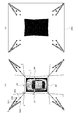
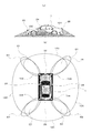
- FIG. 3 shows that the vehicle 1 and four thin columnar objects (first columnar object 301, second columnar object 302, third columnar object 303, and fourth columnar object 304) stand vertically to the road surface. It shows a state in which they are arranged at the positions of the four vertices of the square.
- the shooting ranges of the first camera 22 and the second camera 24 will be described, but the same applies to the shooting ranges of other cameras.
- the cameras 22 and 24 are installed in the horizontal direction, the first camera 22 captures the range of ⁇ XPX ′, and the second camera 24 captures the range of ⁇ YQY ′. .
- the vehicle 1 is assumed to be on a horizontal road surface.
- a flat first virtual screen 200 perpendicular to the road surface is installed at a position that divides OXOY into two equal parts.
- the first columnar object 301 and the third columnar object 303 are standing at a position overlapping the first virtual screen 200.
- the virtual screen projection image generation unit 40 projects the gray value of the image I 1 (x, y) photographed by the first camera 22 onto the first virtual screen 200, as shown in FIG. As illustrated in FIG. 4B, the gray value of the image I 2 (x, y) captured by the second camera 24 is projected onto the first virtual screen 200.
- Projection conversion to a virtual screen means that the image actually captured by the camera is an image of an object that originally existed on the virtual screen, and a value corresponding to the gray value of the captured image It is stored at the corresponding position on the screen.
- this projection conversion is executed as follows.
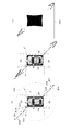
- attention is focused on the pixel (x 0 , y 0 ) constituting the image of the second columnar object 302 shown in the image I 1 (x, y).
- the grayscale value I 1 (x 0 , y 0 ) stored in the pixel (x 0 , y 0 ) is the second columnar shape of interest from the principal point position P of the first camera 22 shown in FIG.
- a half line extending toward the pixel (x 0 , y 0 ) constituting the object 302 is projected to a point intersecting the first virtual screen 200, and the gray value I 1 (x 0 , y 0 ) is stored.
- the virtual screen projection image 301P of the first columnar object 301P and the third columnar object 303 of the first columnar object 303 are displayed on the first virtual screen 200.
- a virtual screen projection image 303P and a virtual screen projection image 304P of the fourth columnar object 304 are respectively generated (see FIG. 4A).
- the virtual screen projection image 301Q of the first columnar object 301Q and the second columnar shape are displayed on the first virtual screen 200.
- a virtual screen projection image 302Q of the object 302, a virtual screen projection image 303Q of the third columnar object 303, and a virtual screen projection image 304Q of the fourth columnar object 304 are generated (see FIG. 4B).
- a first virtual screen projection image 205 shown in FIG. 4C is generated.
- the image I 1 (x, y) is used here.
- the gray value of the image I 2 (x, y) are respectively multiplied by 1/2 and added.
- the four columnar objects 301, 302, 303, and 304 stand upright on the road surface, and the first camera 22 and the second camera 24 are installed horizontally for the sake of simplicity.
- virtual screen projection images of the columnar objects 301, 302, 303, and 304 are generated in a band shape in the vertical direction of the screen.
- the four columnar objects 301, 302, 303, 304 and the vehicle 1 are in the positional relationship shown in FIG. 3, the four columnar objects 301, 302, 303, 304 are both the first camera 22, 4 and projected onto the first virtual screen 200 through the second camera 24, and as shown in FIG. 4A, four virtual screen projection images are generated as viewed from the first camera 22, and are shown in FIG. As shown, four virtual screen projection images are generated as viewed from the second camera 24.
- the virtual screen projection images are overlapped with each other, so that five virtual screen projection images are generated as shown in FIG.
- the five virtual screen projection images shown in FIG. 4C are, in order from the left, the virtual screen projection image 304P, the virtual screen projection image 302Q, the virtual screen projection images 301P and 301Q, the virtual screen projection images 303P and 303Q, and the virtual screen. These correspond to the projected images 302P and 304Q, respectively.
- the number of projected images of the virtual screen depends on the position of the columnar object and the position of the virtual screen.
- the procedure for the projection conversion to the virtual screen is performed by the virtual screen projection image calculation unit 42, and the points intersecting the first virtual screen 200 are defined as the image I 1 (x, y) and the image I 2 (x, y). Since the calculation load for each pixel is large, the image I 1 (x) projected on any pixel of the first virtual screen projection image 205 based on the arrangement of the first camera 22 and the second camera 24. , Y) and the coordinate value of the image I 2 (x, y) are calculated in advance, a coordinate conversion table is created in advance based on the calculation result, and stored in the first coordinate conversion data storage unit 44. Keep it.
- the virtual screen projection image calculation unit 42 reduces the calculation load by executing projection conversion by performing coordinate replacement based on the coordinate conversion table stored in the first coordinate conversion data storage unit 44. ing.
- Similar projection transformations are performed by the second virtual screen 210 installed in the second overlapping area E2, the third virtual screen 220 installed in the third overlapping area E3, and the fourth virtual screen 230 installed in the fourth overlapping area E4. It is also executed against. As a result, four virtual screen projection images (first virtual screen projection image 205, second virtual screen projection image 215, third virtual screen projection image 225, and fourth virtual screen projection image 235) are generated.
- the road projection image calculation unit 52 converts the images I 1 (x, y), I 2 (x, y), I 3 (x, y), and I 4 (x, y) into road surfaces, respectively. And further converted into an image looking down from directly above the vehicle (S8 in FIG. 5).
- the virtual screen projection image described above was generated on the assumption that the image captured by the camera contains an image of an object existing on the virtual screen, whereas the road surface projection image was captured by the camera.
- the generated image is an image generated on the assumption that an image of an object existing on the road surface is reflected.
- the generation of the road surface projection image is performed by the road surface projection image calculation unit 52.
- the image I 1 (x, y) specifically, from the principal point position P of the first camera 22 to the first camera 22. This is performed by obtaining a point where a half line extending toward each pixel of the photographed image I 1 (x, y) intersects the road surface.
- a road surface projection image is generated in the same manner for the image I 2 (x, y).
- the road surface projection image calculation unit 52 reduces the calculation load by executing projection conversion by replacing coordinates based on the coordinate conversion table stored in the second coordinate conversion data storage unit 56.
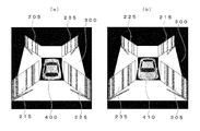
- FIG. 6 shows how the image I 1 (x, y) photographed by the first camera 22 and the image I 2 (x, y) photographed by the second camera 24 are converted into road projection images in the arrangement of FIG. Show.
- Each of 304 is converted to fall on the road projection image so as to move away from the first camera 22 along the direction connecting the principal point position P of the first camera 22 and each columnar object.
- the first columnar object 301 to the fourth columnar object 304 shown in the image I 2 (x, y) photographed by the second camera 24 are respectively on the road surface projection image. Are converted so as to fall away from the second camera 24 along the direction connecting the principal point position Q of the second camera 24 and each columnar object.
- the road projection image combining unit 54 from the image I 1 (x, y), the image I 2 (x, y), the image I 3 (x, y), and the image I 4 (x, y), respectively.
- the converted road projection image is synthesized into one image.
- the road projection image of the image I 1 (x, y) and the road projection image of the image I 2 (x, y) divide the overlapping area of the shooting range of the first camera 22 and the shooting range of the second camera 24 into two equal parts.
- the straight line AO is combined as a boundary line. That is, of the road surface projection images displayed in FIGS. 6A and 6B, an image projected across the straight line AO is not reflected in the composite image.
- the road surface projection images of the first columnar object 301 and the third columnar object 303 that exist on the straight line AO that is the joint of the road surface projection images are the portions where the columnar objects are in contact with the road surface. Disappears, leaving behind.
- a specific value is stored by replacing a gray value with a minimum value or a maximum value, and information is missing. To the driver. In this way, a combined road surface projection image 300 shown in FIG. 7B is generated.
- the four virtual screen projection images generated in S7 of FIG. 5 are converted by the first viewpoint conversion unit 60 into images observed from a predetermined viewpoint position toward a predetermined line-of-sight direction.
- the predetermined viewpoint position and the predetermined gaze direction are determined by the virtual viewpoint position / virtual gaze direction setting unit 66 based on the information detected by the operation detection unit 10.
- the virtual viewpoint is set to the rear sky of the vehicle 1, and the front side of the vehicle 1 is looked down from there.
- a virtual line-of-sight direction is set (S10 in FIG. 5).
- a coordinate conversion table for converting viewpoints as if the four virtual screen projection images were observed from the set virtual viewpoint position toward the set virtual visual line direction is stored in advance.
- the first viewpoint conversion calculation unit 62 performs viewpoint conversion based on the coordinate conversion table (S12 in FIG. 5).
- the composite road surface projection image 300 generated in S8 of FIG. 5 is directed to the same viewpoint position and the same sight line direction set by the second viewpoint conversion unit 70 in the virtual viewpoint position / virtual sight line direction setting unit 66. Converted to the observed image.
- a coordinate conversion table for converting the viewpoint of the composite road surface projection image 300 as observed from the set virtual viewpoint position toward the set virtual visual line direction. are created and stored in advance, and the viewpoint conversion is performed by the second viewpoint conversion calculation unit 72 based on the coordinate conversion table (S13 in FIG. 5).
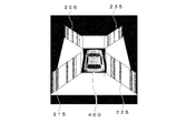
- first virtual screen projection image 205 second virtual screen projection image 215, third virtual screen projection image 225, and fourth virtual screen
- the projection image 235) and the combined road surface projection image 300 generated by the second viewpoint conversion calculation unit 72 are virtual screen projection images (205, 215, 225, 235) on the front and the combined road surface projection image 300 on the back.
- the image composition unit 80 composes one image (S14 in FIG. 5).
- This image composition is performed by the image composition calculation unit 82 based on the transmittance determined by the transmittance setting unit 84.
- the first virtual screen projection image 205 generated by the first viewpoint conversion calculation unit 62 is K (x, y)
- the combined road surface projection image 300 generated by the second viewpoint conversion calculation unit 72 is L (x, y).
- M (x, y) is an image synthesized by the image synthesis unit 80
- M (x, y) is calculated by Equation 1.
- ⁇ is a transmittance parameter. That is, ⁇ is a value corresponding to the transmittance of the image arranged on the front surface when two images overlap, and takes a range of 0 ⁇ ⁇ ⁇ 1.
- the blacked-out areas are areas other than the virtual field projection image and the combined road surface projection image, which are in the vicinity of the position where the vehicle 1 is located and are out of the field of view of the photographing unit 20.
- a rearward first vehicle icon 400 may be superimposed and displayed at the position where the vehicle 1 is present to more clearly represent the positional relationship between the front and rear.
- the composite image of FIG. 8A obtained in this way is DA-converted by the encoder 92 and displayed on the display monitor 94 installed inside the vehicle 1 (S15 in FIG. 5).
- the vehicle speed is always detected by the vehicle speed detection unit 14, and when the detected vehicle speed exceeds a predetermined value (S16 in FIG. 5), the displayed image is returned to the state before starting the apparatus. (S20 in FIG. 5), the vehicle surrounding monitoring device 2 shifts to a non-display state (S1 in FIG. 5).
- the end switch operation detecting unit 12 detects that the end switch 18 is operated (S18 in FIG. 5)
- the displayed image is returned to the state before the activation of the apparatus (S20 in FIG. 5).
- the vehicle surroundings monitoring device 2 shifts to a non-display state (S1 in FIG. 5).
- the shift position detection unit 13 detects that the shift position is in the reverse position (S3 in FIG. 5)
- 2 is stored in the variable ⁇ representing the state of the system (S5 in FIG. 5).
- the virtual viewpoint is set in the sky above the vehicle 1, and the virtual line-of-sight direction overlooking the rear side of the vehicle 1 is set (S11 in FIG. 5).
- the virtual screen projection image and the combined road surface projection image 300 generated in the same manner as when the vehicle is moving forward are combined by the image combining calculation unit 82 and displayed as an image looking down at the rear of the vehicle as shown in FIG. Is displayed on the monitor 94 (S15 in FIG. 5).
- a forward-facing second vehicle icon 410 may be superimposed and displayed at the position where the vehicle 1 is present so that the positional relationship between the front and rear is more clearly expressed.
- the vehicle speed is constantly monitored by the vehicle speed detection unit 14, and when the vehicle speed exceeds a predetermined value (S16 in FIG. 5), it is not preferable for safety to display an image around the vehicle.
- the displayed image is returned to the state before the activation of the apparatus (S20 in FIG. 5), and the display state of the vehicle surrounding monitoring apparatus 2 is exited (S1 in FIG. 5).
- the shift position detection unit 13 always detects the shift position and detects that the shift position is other than the reverse position (S19 in FIG. 5).
- the displayed image is displayed before starting up the apparatus. (S20 in FIG. 5), the display state of the vehicle surrounding monitoring device 2 is exited (S1 in FIG. 5).
- the vehicle surrounding monitoring apparatus 2 even if a three-dimensional object exists in the boundary part of the shooting range of adjacent cameras, a virtual screen is installed in the boundary part, By generating a projection image on the virtual screen and displaying the projection image, the three-dimensional object can be accurately displayed without causing a blind spot. Therefore, the situation around the vehicle can be accurately transmitted to the driver, and thereby vehicle guidance such as parking operation and turn-back operation can be performed smoothly.
- the virtual screen projection image and the combined road surface projection image are combined and displayed, but the format is not limited. That is, only the virtual screen projection image may be displayed as shown in FIG.
- the display method of FIG. 9 it is possible to accurately display the state of obstacles in the vicinity of the vehicle in the vicinity of the joint of the image in which the blind spot is generated.
- the four virtual screen projection images and the combined road surface projection image are combined and displayed on one image, but the format is not limited. That is, when the vehicle moves forward, only the first virtual screen projection image 205, the fourth virtual screen projection image 235, and the combined road surface projection image 300 may be combined and displayed in FIG. This is because, when the virtual viewpoint position and the virtual viewpoint direction are set by the virtual viewpoint position / virtual line-of-sight direction setting unit 66, the first virtual screen projection image 205 and the fourth virtual screen are stored in the third coordinate conversion data storage unit 64. This can be realized by giving an instruction to create only the screen projection image 235.
- the second virtual screen projection image 215, the third virtual screen projection image 225, and the combined road surface projection image 300 may be combined and displayed in FIG. 8B.
- the second virtual screen projection image 215 and the third virtual screen are output to the third coordinate conversion data storage unit 64.
- This can be realized by giving an instruction to create only the screen projection image 225.
- the present invention is applied to a vehicle surrounding monitoring device 4 that can display the situation around the vehicle photographed by a plurality of cameras installed in the vehicle in a form that is easy to see for the driver. is there.
- the second embodiment includes an obstacle detection unit around the vehicle. Based on the output of the obstacle detection unit, an image around the vehicle is converted into a more easily understood form and displayed on a monitor installed in the vehicle. To do.
- FIG. 10 is a block diagram showing a configuration of the vehicle surrounding monitoring device 4 according to the second embodiment of the present invention.
- the vehicle surrounding monitoring device 4 is installed in a vehicle 1 (not shown), and an operation detection unit 10 that detects a start operation and an end operation of the vehicle surrounding monitoring device 4 by a driver, An operation switch 15 that is installed within the reach of the driver and that instructs activation and termination of the vehicle surroundings monitoring device 4, an imaging unit 20 that includes a plurality of cameras that capture images around the vehicle, and an imaging unit
- the virtual screen setting unit 30 that sets a virtual screen in an overlapping portion of the shooting areas of adjacent cameras among the plurality of cameras that constitute the image 20, and the virtual screen set by the virtual screen setting unit 30 shoots with the adjacent camera
- a virtual screen projection image generation unit 40 that projects each of the images generated to generate a virtual screen projection image, and projects a captured image of the surroundings of the vehicle onto the road surface to project the road surface
- a road surface projection image generation unit 50 that generates an image and a virtual screen projection image generated by the virtual screen projection image generation unit 40 are converted into an image captured from a predetermined virtual viewpoint toward a predetermined virtual
- An image synthesis unit 80 that synthesizes the virtual screen projection image converted by the first viewpoint conversion unit 60 and the road surface projection image converted by the second viewpoint conversion unit 70 into a single image;
- the image display unit 90 displays a synthesized image, and the obstacle detection unit 100 detects the presence or absence of an obstacle around the vehicle 1 and calculates the distance to the obstacle.
- the operation detection unit 10 includes a start switch operation detection unit 11 that detects a driver's start operation of the vehicle surroundings monitoring device 4 and an end switch operation detection unit 12 that detects an end operation of the vehicle surroundings monitoring device 4. And a shift position detector 13 for detecting the shift position of the vehicle and a vehicle speed detector 14 for detecting the vehicle speed.
- the operation switch 15 includes an activation switch 16 for instructing activation of the vehicle surrounding monitoring device 4 and an end switch 18 for instructing termination of the vehicle surrounding monitoring device 4.
- the imaging unit 20 is installed around the vehicle as shown in FIG. 11, and the first camera 22, the second camera 24, the third camera 26, and the fourth camera are arranged so that adjacent imaging regions overlap each other.
- the third decoder 27 converts the output signal of the camera 26 into a digital signal by AD conversion
- the fourth decoder 29 converts the output signal of the fourth camera 28 into a digital signal by AD conversion.
- the virtual screen projection image generation unit 40 is created in advance based on the installation positions of the first camera 22 to the fourth camera 28 and the installation positions of the virtual screen in order to generate a virtual screen projection image.
- a first coordinate conversion data storage unit 44 storing the coordinate conversion data table, and a virtual screen for generating a virtual screen projection image based on the coordinate conversion data table stored in the first coordinate conversion data storage unit 44
- a projection image calculation unit 42 a projection image calculation unit 42.
- the road surface projection image generation unit 50 stores a coordinate conversion data table created in advance based on the installation positions of the first camera 22 to the fourth camera 28 in order to generate a road surface projection image. Based on the coordinate conversion data table stored in the second coordinate conversion data storage unit 56 and the second coordinate conversion data storage unit 56, a road surface projection image calculation unit that generates a road surface projection image from an image captured by each camera. 52 and a road surface projection image combining unit 54 that combines the plurality of generated road surface projection images into one image.
- the first viewpoint conversion unit 60 generates a composite image of the virtual screen projection image and the road surface projection image based on the traveling direction of the vehicle 1 and the driver's switch operation.
- a virtual viewpoint projection / virtual line-of-sight direction setting unit 66 to be set and a virtual screen projection image viewpoint conversion from the virtual viewpoint position set by the virtual viewpoint position / virtual line-of-sight direction setting unit 66 toward the virtual line-of-sight direction A third coordinate conversion data storage unit 64 in which a coordinate conversion data table is stored, and a first screen for performing viewpoint conversion of the virtual screen projection image based on the coordinate conversion data table stored in the third coordinate conversion data storage unit 64 And a viewpoint conversion calculation unit 62.
- the second viewpoint conversion unit 70 performs coordinate conversion data for performing viewpoint conversion of the road projection image from the virtual viewpoint position set by the virtual viewpoint position / virtual viewing direction setting unit 66 toward the virtual viewing direction.
- the second viewpoint conversion calculation unit 72 that converts the viewpoint of the road projection image. It consists of.
- the image synthesis unit 80 synthesizes the virtual screen projection image converted by the first viewpoint conversion unit 60 and the road surface projection image converted by the second viewpoint conversion unit 70 into one image.
- a transmittance setting unit 84 that sets the transmittance of the overlapping portion of the image, and the virtual screen projection image that has been subjected to viewpoint conversion by the first viewpoint conversion unit 60 with the transmittance set by the transmittance setting unit 84
- an image composition calculation unit 82 for compositing the road surface projection image converted by the second viewpoint conversion unit 70 with the back surface.
- the image display unit 90 includes an encoder 92 that converts the image synthesized by the image synthesis unit 80 from a digital signal into an analog signal, and a display monitor 94 that displays an image converted into an analog signal by the encoder 92. Consists of.
- the obstacle detection unit 100 is specifically installed around the vehicle 1 as shown in FIG. 11, and is a first overlapping region E1 that is an overlapping range of the shooting range of the first camera 22 and the shooting range of the second camera 24.
- the first distance measurement unit 102 for calculating the presence / absence of an obstacle in the first distance measurement range R1 including the distance to the obstacle, the overlapping range of the shooting range of the second camera 24 and the shooting range of the third camera 26
- the second distance measuring unit 104 that calculates the presence / absence of an obstacle in the second distance measurement range R2 including a certain second overlapping area E2 and the distance to the obstacle, the photographing range of the third camera 26, and the fourth camera 28
- the third ranging unit 106 that calculates the presence / absence of an obstacle in the third ranging range R3 including the third overlapping area E3 that is the overlapping range of the imaging range and the distance to the obstacle, and the imaging range of the fourth camera 28 And the fourth overlapping area, which is the overlapping range of the shooting range of the first camera 22
- the vehicle periphery monitoring device 4 according to the present invention is used when a vehicle is parked or turned back in a narrow place, and assists driving operation by presenting an image around the vehicle to the driver.
- the first camera 22 is installed on the front bumper of the vehicle 1
- the second camera 24 is installed on the left door mirror of the vehicle 1
- the third camera 26 is installed on the rear bumper of the vehicle 1.
- the fourth camera 28 is installed on the right door mirror of the vehicle 1.
- the first distance measuring section 102 is on the front bumper left corner
- the second distance measuring section 104 is on the rear bumper left corner
- the third distance measuring section 106 is on the rear bumper right corner.
- the distance measuring unit 108 is installed at the right corner of the front bumper.
- These distance measuring units are specifically composed of an ultrasonic sensor or an optical distance measuring sensor, but the structure is not limited as long as it has a distance measuring function.
- each camera is installed so as to photograph a range in which the photographing range and the road surface intersect at each intersection line 120, 122, 124, 126.
- the adjacent cameras 22 and 24, 24 and 26, 26 and 28, and 28 and 22 have overlapping shooting ranges, and the first overlap region E1 and the second overlap. It is installed so as to have an area E2, a third overlapping area E3, and a fourth overlapping area E4.
- the first distance measuring unit 102 sets the area including the first overlapping area E1 as the first distance measuring range R1
- the second distance measuring section 104 sets the area including the second overlapping area E2 as the second distance measuring range R2.
- the third ranging unit 106 sets the area including the third overlapping area E3 as the third ranging range R3
- the fourth ranging unit 108 sets the area including the fourth overlapping area E4 as the fourth ranging range R4. It is arranged so that.
- the operation of the second embodiment will be described with respect to a scene in which the vehicle 1 moves forward at a slow speed for parking.
- the driver monitors the surroundings of the vehicle, the driver operates the start switch 16 installed in the vehicle.
- the activation switch operation detection unit 11 detects the activation switch operation (S2 in FIG. 12).
- 1 is given to the variable ⁇ representing the state of the vehicle surrounding monitoring device 4 (S4 in FIG. 12).
- Images captured by the first camera 22 to the fourth camera 28 are sampled and quantized by the first decoder 23 to the fourth decoder 29 and converted into digital images (S6 in FIG. 12). Note that an image captured by the first camera 22 is I 1 (x, y), an image captured by the second camera 24 is I 2 (x, y), and an image captured by the third camera 26 is I 3. (X, y), and an image taken by the fourth camera 28 is I 4 (x, y).
- the first distance measuring section 102 to the fourth distance measuring section 108 measure the distance around the vehicle, and correspond to the distance from each distance measuring section to the obstacle around the vehicle 1. Is output.
- the four columnar objects on the left front side of the vehicle are inside the attention-requiring area 420 that requires attention when performing the parking operation, and the four columnar objects on the right rear side of the vehicle are the attention-requiring area 420. It shall be outside of
- a smaller value corresponding to the distance is output as the distance from the road surface to the object (obstacle) having a height is shorter.
- the smallest value is output from the first distance measuring unit 102, and the next smallest value is output from the third distance measuring unit 106. Since there are no obstacles on the left rear and right front of the vehicle 1, the second distance measuring unit 104 and the fourth distance measuring unit 108 output very large values indicating that no obstacle exists. .
- the values output from the four distance measuring units are sent to the distance value determining unit 109, and the presence / absence and the position of the distance measuring unit that outputs a value equal to or less than a predetermined value are determined. Identified. In the case of this example, it is specified that a value equal to or smaller than a predetermined value is output from the first distance measuring unit 102 (S7 in FIG. 12).
- the virtual screen installation unit 30 installs the first virtual screen 200 that is planar and perpendicular to the road surface extending in the perspective direction from the vehicle so that the area of the first overlapping region E1 is divided into two equal parts. .
- the virtual screen projection image generation unit 40 projects and converts the image I 1 (x, y) and the image I 2 (x, y) on the first virtual screen 200 that is installed, thereby generating a virtual screen projection image. (S8 in FIG. 12). Since the generation method of the virtual screen projection image is as described in the first embodiment, the description is omitted here.
- the virtual screen projection image is generated by the virtual screen projection image calculation unit 42, and a point intersecting the first virtual screen 200 is determined for each pixel of the image I 1 (x, y) and the image I 2 (x, y). Since the calculation load is large, the image I 1 (x, y) projected on an arbitrary pixel of the first virtual screen projection image 205 based on the arrangement of the first camera 22 and the second camera 24 is calculated. ) And image I 2 (x, y) are calculated in advance, a coordinate conversion table is created in advance based on the calculation result, and stored in the first coordinate conversion data storage unit 44. .
- the virtual screen projection image calculation unit 42 reduces the calculation load by performing projection conversion by performing coordinate replacement operation based on the coordinate conversion table stored in the first coordinate conversion data storage unit 44. is doing. By this projection conversion, a first virtual screen projection image 205 is generated.
- the road projection image calculation unit 52 converts the images I 1 (x, y), I 2 (x, y), I 3 (x, y), and I 4 (x, y) into road surfaces, respectively. And further converted into an image looking down from directly above the vehicle (S9 in FIG. 12).
- the road surface projection image is generated by the road surface projection image calculation unit 52.
- the first camera 22 captures the image from the principal point position P of the first camera 22.
- the half line extending toward each pixel of the image I 1 (x, y) is obtained by obtaining a point where the road surface intersects.
- a road surface projection image is generated in the same manner for the image I 2 (x, y).
- FIG. 13A When the environment in which the second embodiment is operating is FIG. 13A, road surface projection images of four images taken by four cameras are synthesized as shown in FIG. 13B.
- a specific value is stored by replacing a gray value with a minimum value or a maximum value, and information is missing. Let the driver know. In this way, a composite road surface projection image 300 shown in FIG. 13C is generated.
- the first virtual screen projection image 205 generated in S8 of FIG. 12 is converted by the first viewpoint conversion unit 60 into an image observed from a predetermined viewpoint position toward a predetermined visual line direction.
- the predetermined viewpoint position and the predetermined gaze direction are determined by the virtual viewpoint position / virtual gaze direction setting unit 66 based on the information detected by the operation detection unit 10.
- the virtual viewpoint is set to the rear sky of the vehicle 1, and the front side of the vehicle 1 is looked down from there.
- a virtual line-of-sight direction is set (S11 in FIG. 12).
- the third coordinate conversion data storage unit 64 a coordinate conversion table for converting the viewpoint as if the virtual screen projection image was observed from the set virtual viewpoint position toward the set virtual visual line direction is created in advance. Based on the stored coordinate conversion table, the first viewpoint conversion calculation unit 62 performs viewpoint conversion (S13 in FIG. 12).
- the composite road surface projection image 300 generated in S9 of FIG. 12 is directed to the same line-of-sight direction from the same viewpoint position set by the virtual viewpoint position / virtual line-of-sight direction setting unit 66 by the second viewpoint conversion unit 70. Converted to the observed image.
- the fourth coordinate conversion data storage unit 74 includes a coordinate conversion table for performing viewpoint conversion so that the synthesized road surface projection image 300 is observed from the set virtual viewpoint position toward the set virtual visual line direction.
- the viewpoint conversion is performed by the second viewpoint conversion calculation unit 72 based on the coordinate conversion table (S14 in FIG. 12).
- the first virtual screen projection image 205 generated by the first viewpoint conversion calculation unit 62 and the composite road surface projection image 300 generated by the second viewpoint conversion calculation unit 72 are the first virtual screen projection image 205.
- the synthesized road surface projection image 300 is placed on the front side and the image is synthesized by the image synthesis unit 80 (S15 in FIG. 12).
- This image composition is performed by the image composition calculation unit 82 based on the rule determined by the transmittance setting unit 84.
- the first virtual screen projection image 205 generated by the first viewpoint conversion calculation unit 62 is K (x, y)
- the combined road surface projection image 300 generated by the second viewpoint conversion calculation unit 72 is L (x, y).
- M (x, y) is an image synthesized by the image synthesizing unit 80
- M (x, y) is calculated by Equation 1 described above.
- the transmittance parameter ⁇ takes a value in the range of 0 ⁇ ⁇ ⁇ 1.
- ⁇ 1 is set. This is a setting in which when the virtual screen projection image (205, 215, 225, 235) and the combined road surface projection image 300 overlap, the combined road surface projection image 300 combined on the back surface is made invisible.
- the blacked-out areas are areas other than the virtual field projection image and the combined road surface projection image, which are in the vicinity of the position where the vehicle 1 is located and are out of the field of view of the photographing unit 20.
- a rearward first vehicle icon 400 may be superimposed and displayed at the position where the vehicle 1 is present to more clearly represent the front-rear positional relationship.
- the synthesized image of FIG. 14A obtained in this way is DA-converted by the encoder 92 and displayed on the display monitor 94 installed inside the vehicle 1 (S16 in FIG. 12).
- the vehicle speed is always detected by the vehicle speed detection unit 14, and when the detected vehicle speed exceeds a predetermined value (S17 in FIG. 12), the displayed image is returned to the state before the activation of the apparatus. (S21 in FIG. 12), the vehicle periphery monitoring device 4 shifts to a non-display state (S1 in FIG. 12).
- the end switch operation detection unit 12 detects that the end switch 18 has been operated (S19 in FIG. 12)
- the displayed image is returned to the state before the activation of the apparatus (S21 in FIG. 12).
- the vehicle periphery monitoring device 4 shifts to a non-display state (S1 in FIG. 12).
- the shift position detection unit 13 detects that the shift position is in the reverse position (S3 in FIG. 12)
- 2 is stored in the variable ⁇ representing the state of the system (S5 in FIG. 12).
- the virtual viewpoint is set in the sky above the vehicle 1, and the virtual line-of-sight direction overlooking the rear side of the vehicle 1 is set (S12 in FIG. 12).
- the virtual screen projection image and the combined road surface projection image 300 generated in the same manner as when the vehicle is moving forward are combined by the image combining calculation unit 82 and displayed as an image looking down at the rear of the vehicle as shown in FIG. Is displayed on the monitor 94 (S16 in FIG. 12).
- a forward-facing second vehicle icon 410 may be superimposed and displayed at the position where the vehicle 1 is present so that the positional relationship between the front and rear is more clearly expressed.
- the vehicle speed is always detected by the vehicle speed detection unit 14, and when the detected vehicle speed exceeds a predetermined value (S17 in FIG. 12), the displayed image is returned to the state before starting the apparatus. (S21 in FIG. 12), the vehicle periphery monitoring device 4 shifts to a non-display state (S1 in FIG. 12).
- the shift position detection unit 13 If the shift position is always detected by the shift position detection unit 13 and it is detected that the shift position is other than the reverse position (S20 in FIG. 12), the displayed image is displayed before starting the apparatus. (S21 in FIG. 12), the vehicle surroundings monitoring device 4 shifts to a non-display state (S1 in FIG. 12).
- a virtual screen is installed only in an area where an obstacle is detected, and a virtual screen projection image is generated for the virtual screen.
- the virtual screen projection image is displayed only when there is an obstacle at the joint position of the image that becomes a blind spot. The property can be further improved.
- a virtual screen is installed at a location corresponding to the area where the obstacle is detected.
- the composite image is generated with the composite road surface projection image 300 overlapping the virtual screen projection image generated by projecting on the virtual screen being made invisible, but the format is not limited.
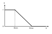
- the transmittance parameter ⁇ is set to 1 to make the combined road surface projection image 300 invisible, and further, Dmin ⁇
- Di ⁇ Dmax the smaller the value Di corresponding to the distance, the more transparent
- the distance value determination unit 109 observes the time change of the values D1 to D4 corresponding to the distances from the first distance measurement unit 102 to the obstacles output from each of the fourth distance measurement units 108, and each Di.
- a planar virtual screen perpendicular to the road surface extending in the perspective direction from the vehicle is installed at a position that bisects the area of the overlapping area of the shooting ranges of adjacent cameras. You will not be trapped by.
- the distance measuring unit (102, 104, 106, 108) has a function of measuring distance information for each angle in the horizontal direction by scanning the distance measuring range in the horizontal direction (vehicle peripheral direction), and obstructing the obstacle.
- a planar virtual screen extending vertically from the road surface extending in the direction in which information is obtained may be installed, and a virtual screen projection image may be generated and displayed on the virtual screen.
- the obstacle image in the virtual screen projection image is virtualized from two adjacent cameras that photograph the obstacle. Projected to the same position on the screen, therefore, on the virtual screen projection image, the shade value of the image representing the obstacle is added to a larger value, thereby displaying the obstacle more clearly and improving the visibility of the image. The effect of improving is acquired.
Landscapes
- Engineering & Computer Science (AREA)
- Multimedia (AREA)
- Physics & Mathematics (AREA)
- General Physics & Mathematics (AREA)
- Theoretical Computer Science (AREA)
- Mechanical Engineering (AREA)
- Closed-Circuit Television Systems (AREA)
- Image Processing (AREA)
- Traffic Control Systems (AREA)
Abstract
L'invention concerne une unité d'établissement d'écran virtuel (30) qui établit, dans les jonctions des images prises par une unité d'imagerie (20), un écran virtuel perpendiculaire à la surface de la route et s'étendant dans la direction s'éloignant du véhicule ; une unité de génération d'image (40) de projection sur écran virtuel qui transforme les images capturées par l'unité d'imagerie (20) en vue de leur projection sur l'écran virtuel et qui génère une image de projection sur écran virtuel qui est affichée par une unité d'affichage d'image (90).
Priority Applications (3)
| Application Number | Priority Date | Filing Date | Title |
|---|---|---|---|
| CN201180011651.5A CN102783143B (zh) | 2010-03-10 | 2011-03-08 | 车辆用周围监视装置 |
| US13/582,494 US9142129B2 (en) | 2010-03-10 | 2011-03-08 | Vehicle surroundings monitoring device |
| EP11753359.6A EP2536140B1 (fr) | 2010-03-10 | 2011-03-08 | Dispositif de surveillance de l'environnement d'un véhicule |
Applications Claiming Priority (2)
| Application Number | Priority Date | Filing Date | Title |
|---|---|---|---|
| JP2010052762A JP5479956B2 (ja) | 2010-03-10 | 2010-03-10 | 車両用周囲監視装置 |
| JP2010-052762 | 2010-03-10 |
Publications (1)
| Publication Number | Publication Date |
|---|---|
| WO2011111701A1 true WO2011111701A1 (fr) | 2011-09-15 |
Family
ID=44563501
Family Applications (1)
| Application Number | Title | Priority Date | Filing Date |
|---|---|---|---|
| PCT/JP2011/055371 WO2011111701A1 (fr) | 2010-03-10 | 2011-03-08 | Dispositif de surveillance de l'environnement d'un véhicule |
Country Status (5)
| Country | Link |
|---|---|
| US (1) | US9142129B2 (fr) |
| EP (1) | EP2536140B1 (fr) |
| JP (1) | JP5479956B2 (fr) |
| CN (1) | CN102783143B (fr) |
| WO (1) | WO2011111701A1 (fr) |
Cited By (1)
| Publication number | Priority date | Publication date | Assignee | Title |
|---|---|---|---|---|
| CN104081763A (zh) * | 2012-01-17 | 2014-10-01 | 日本先锋公司 | 图像处理装置、图像处理服务器、图像处理方法、图像处理程序以及记录介质 |
Families Citing this family (38)
| Publication number | Priority date | Publication date | Assignee | Title |
|---|---|---|---|---|
| JP5362639B2 (ja) * | 2010-04-12 | 2013-12-11 | 住友重機械工業株式会社 | 画像生成装置及び操作支援システム |
| JP5476216B2 (ja) * | 2010-06-01 | 2014-04-23 | クラリオン株式会社 | 車両用周囲監視装置 |
| US8768583B2 (en) * | 2012-03-29 | 2014-07-01 | Harnischfeger Technologies, Inc. | Collision detection and mitigation systems and methods for a shovel |
| JP5629740B2 (ja) * | 2012-09-21 | 2014-11-26 | 株式会社小松製作所 | 作業車両用周辺監視システム及び作業車両 |
| CN104885448B (zh) * | 2013-02-21 | 2018-04-06 | 本田技研工业株式会社 | 驾驶辅助装置以及图像处理程序 |
| JP6148887B2 (ja) | 2013-03-29 | 2017-06-14 | 富士通テン株式会社 | 画像処理装置、画像処理方法、及び、画像処理システム |
| CN103253196A (zh) * | 2013-05-30 | 2013-08-21 | 吕军 | 汽车全视纪录镜 |
| US9969330B2 (en) | 2013-06-26 | 2018-05-15 | Conti Temic Microelectronic Gmbh | Mirror substitute device and vehicle |
| JP6347934B2 (ja) * | 2013-10-11 | 2018-06-27 | 株式会社デンソーテン | 画像表示装置、画像表示システム、画像表示方法、及び、プログラム |
| DE102014107235A1 (de) * | 2014-05-22 | 2015-11-26 | Dr. Ing. H.C. F. Porsche Aktiengesellschaft | Verfahren zur Darstellung einer Fahrzeugumgebung auf einer Anzeigevorrichtung; eine Anzeigevorrichtung; ein System aus einer Mehrzahl an Bilderfassungseinheiten und einer Anzeigevorrichtung; ein Computerprogramm |
| KR101587147B1 (ko) * | 2014-06-10 | 2016-01-20 | 엘지전자 주식회사 | 차량용 어라운드뷰 제공 장치 및 이를 구비한 차량 |
| DE102014213536A1 (de) * | 2014-07-11 | 2016-01-14 | Bayerische Motoren Werke Aktiengesellschaft | Zusammenfügen von Teilbildern zu einem Abbild einer Umgebung eines Fortbewegungsmittels |
| JP6651702B2 (ja) * | 2015-03-23 | 2020-02-19 | 富士通株式会社 | 物体検出装置、物体検出方法および情報処理プログラム |
| US20160347250A1 (en) * | 2015-05-29 | 2016-12-01 | Andreas Enz | Vehicle System For Providing Indirect View Around A Commercial Vehicle |
| US10157452B1 (en) | 2015-09-28 | 2018-12-18 | Amazon Technologies, Inc. | Image processing system for image rectification |
| JP6759899B2 (ja) * | 2016-09-08 | 2020-09-23 | アイシン精機株式会社 | 車両用画像処理装置 |
| JP6876236B2 (ja) * | 2016-09-30 | 2021-05-26 | 株式会社アイシン | 表示制御装置 |
| JP6501805B2 (ja) * | 2017-01-04 | 2019-04-17 | 株式会社デンソーテン | 画像処理装置および画像処理方法 |
| CN108632934B (zh) | 2017-03-24 | 2021-01-01 | 华为技术有限公司 | 切换的方法和设备 |
| US20180338103A1 (en) * | 2017-05-16 | 2018-11-22 | Bell Helicopter Textron Inc. | Software video combiner |
| DE102017209427B3 (de) * | 2017-06-02 | 2018-06-28 | Volkswagen Aktiengesellschaft | Vorrichtung zur Fahrschlauchabsicherung |
| JP6700222B2 (ja) * | 2017-06-09 | 2020-05-27 | 株式会社Soken | 画像作成装置 |
| JP6686988B2 (ja) * | 2017-08-28 | 2020-04-22 | 株式会社Soken | 映像出力装置及び映像生成プログラム |
| US20200307576A1 (en) * | 2017-09-08 | 2020-10-01 | Mitsubishi Electric Corporation | Driver assistance apparatus and driver assistance method |
| JP2019053508A (ja) * | 2017-09-14 | 2019-04-04 | オムロン株式会社 | 警報表示システム |
| JP7018285B2 (ja) * | 2017-09-29 | 2022-02-10 | 株式会社デンソー | 車両の周辺監視装置および周辺監視方法 |
| JP6915512B2 (ja) * | 2017-11-28 | 2021-08-04 | トヨタ自動車株式会社 | サーバ装置、故障車両推定方法および故障車両推定プログラム |
| US20190241180A1 (en) * | 2018-02-07 | 2019-08-08 | Baidu Usa Llc | Lane self-localization system using multiple cameras for autonomous driving vehicles |
| JP2019151304A (ja) * | 2018-03-06 | 2019-09-12 | アイシン精機株式会社 | 周辺監視装置 |
| JP7074546B2 (ja) * | 2018-04-13 | 2022-05-24 | フォルシアクラリオン・エレクトロニクス株式会社 | 画像処理装置および方法 |
| JP7172309B2 (ja) * | 2018-09-06 | 2022-11-16 | 株式会社アイシン | 周辺監視装置 |
| JP7208356B2 (ja) * | 2018-09-26 | 2023-01-18 | コーヒレント・ロジックス・インコーポレーテッド | 任意の世界ビューの生成 |
| JP2020121638A (ja) * | 2019-01-30 | 2020-08-13 | アイシン精機株式会社 | 表示制御装置 |
| KR102177878B1 (ko) * | 2019-03-11 | 2020-11-12 | 현대모비스 주식회사 | 영상 처리 장치 및 방법 |
| WO2020194715A1 (fr) * | 2019-03-28 | 2020-10-01 | 本田技研工業株式会社 | Véhicule à selle |
| CN112208438B (zh) * | 2019-07-10 | 2022-07-29 | 台湾中华汽车工业股份有限公司 | 行车辅助影像产生方法及系统 |
| CN112835445B (zh) * | 2019-11-25 | 2024-04-26 | 华为技术有限公司 | 虚拟现实场景中的交互方法、装置及系统 |
| JP2022048455A (ja) * | 2020-09-15 | 2022-03-28 | マツダ株式会社 | 車両用表示装置 |
Citations (3)
| Publication number | Priority date | Publication date | Assignee | Title |
|---|---|---|---|---|
| JP2006253872A (ja) * | 2005-03-09 | 2006-09-21 | Toshiba Corp | 車両周辺画像表示装置および車両周辺画像表示方法 |
| JP2007036668A (ja) | 2005-07-27 | 2007-02-08 | Nissan Motor Co Ltd | 俯瞰画像表示システム及び俯瞰画像の表示方法 |
| JP2007180720A (ja) * | 2005-12-27 | 2007-07-12 | Alpine Electronics Inc | 車両運転支援装置 |
Family Cites Families (21)
| Publication number | Priority date | Publication date | Assignee | Title |
|---|---|---|---|---|
| DE10035223A1 (de) * | 2000-07-20 | 2002-01-31 | Daimler Chrysler Ag | Vorrichtung und Verfahren zur Überwachung der Umgebung eines Objekts |
| JP4156214B2 (ja) * | 2001-06-13 | 2008-09-24 | 株式会社デンソー | 車両周辺画像処理装置及び記録媒体 |
| KR100866450B1 (ko) | 2001-10-15 | 2008-10-31 | 파나소닉 주식회사 | 차량 주위 감시 장치 및 그 조정 방법 |
| JP3922245B2 (ja) * | 2003-11-20 | 2007-05-30 | 日産自動車株式会社 | 車両周辺監視装置および方法 |
| JP2006033570A (ja) | 2004-07-20 | 2006-02-02 | Olympus Corp | 画像生成装置 |
| JP4744823B2 (ja) | 2004-08-05 | 2011-08-10 | 株式会社東芝 | 周辺監視装置および俯瞰画像表示方法 |
| JP4934308B2 (ja) * | 2005-10-17 | 2012-05-16 | 三洋電機株式会社 | 運転支援システム |
| DE102006003538B3 (de) * | 2006-01-24 | 2007-07-19 | Daimlerchrysler Ag | Verfahren zum Zusammenfügen mehrerer Bildaufnahmen zu einem Gesamtbild in der Vogelperspektive |
| US8243994B2 (en) | 2006-05-09 | 2012-08-14 | Nissan Motor Co., Ltd. | Vehicle circumferential image providing device and vehicle circumferential image providing method |
| US7728879B2 (en) * | 2006-08-21 | 2010-06-01 | Sanyo Electric Co., Ltd. | Image processor and visual field support device |
| JP2008187564A (ja) * | 2007-01-31 | 2008-08-14 | Sanyo Electric Co Ltd | カメラ校正装置及び方法並びに車両 |
| JP4748082B2 (ja) * | 2007-02-23 | 2011-08-17 | トヨタ自動車株式会社 | 車両用周辺監視装置及び車両用周辺監視方法 |
| JP2009129001A (ja) * | 2007-11-20 | 2009-06-11 | Sanyo Electric Co Ltd | 運転支援システム、車両、立体物領域推定方法 |
| JP5222597B2 (ja) * | 2008-03-19 | 2013-06-26 | 三洋電機株式会社 | 画像処理装置及び方法、運転支援システム、車両 |
| JP2010093605A (ja) * | 2008-10-09 | 2010-04-22 | Sanyo Electric Co Ltd | 操縦支援装置 |
| JP2010141836A (ja) * | 2008-12-15 | 2010-06-24 | Sanyo Electric Co Ltd | 障害物検知装置 |
| JP5068779B2 (ja) * | 2009-02-27 | 2012-11-07 | 現代自動車株式会社 | 車両周囲俯瞰画像表示装置及び方法 |
| JP2010258691A (ja) * | 2009-04-23 | 2010-11-11 | Sanyo Electric Co Ltd | 操縦支援装置 |
| JP5503660B2 (ja) * | 2009-09-24 | 2014-05-28 | パナソニック株式会社 | 運転支援表示装置 |
| TWI417639B (zh) * | 2009-12-30 | 2013-12-01 | Ind Tech Res Inst | 全周鳥瞰影像無縫接合方法與系統 |
| TWI392366B (zh) * | 2009-12-31 | 2013-04-01 | Ind Tech Res Inst | 全周鳥瞰影像距離介面產生方法與系統 |
-
2010
- 2010-03-10 JP JP2010052762A patent/JP5479956B2/ja active Active
-
2011
- 2011-03-08 US US13/582,494 patent/US9142129B2/en active Active
- 2011-03-08 EP EP11753359.6A patent/EP2536140B1/fr active Active
- 2011-03-08 WO PCT/JP2011/055371 patent/WO2011111701A1/fr active Application Filing
- 2011-03-08 CN CN201180011651.5A patent/CN102783143B/zh active Active
Patent Citations (3)
| Publication number | Priority date | Publication date | Assignee | Title |
|---|---|---|---|---|
| JP2006253872A (ja) * | 2005-03-09 | 2006-09-21 | Toshiba Corp | 車両周辺画像表示装置および車両周辺画像表示方法 |
| JP2007036668A (ja) | 2005-07-27 | 2007-02-08 | Nissan Motor Co Ltd | 俯瞰画像表示システム及び俯瞰画像の表示方法 |
| JP2007180720A (ja) * | 2005-12-27 | 2007-07-12 | Alpine Electronics Inc | 車両運転支援装置 |
Cited By (1)
| Publication number | Priority date | Publication date | Assignee | Title |
|---|---|---|---|---|
| CN104081763A (zh) * | 2012-01-17 | 2014-10-01 | 日本先锋公司 | 图像处理装置、图像处理服务器、图像处理方法、图像处理程序以及记录介质 |
Also Published As
| Publication number | Publication date |
|---|---|
| JP2011188335A (ja) | 2011-09-22 |
| JP5479956B2 (ja) | 2014-04-23 |
| CN102783143A (zh) | 2012-11-14 |
| EP2536140A4 (fr) | 2017-02-22 |
| US9142129B2 (en) | 2015-09-22 |
| EP2536140B1 (fr) | 2020-05-13 |
| EP2536140A1 (fr) | 2012-12-19 |
| US20120327238A1 (en) | 2012-12-27 |
| CN102783143B (zh) | 2015-04-01 |
Similar Documents
| Publication | Publication Date | Title |
|---|---|---|
| JP5479956B2 (ja) | 車両用周囲監視装置 | |
| US9156402B2 (en) | Wide view vehicle periphery image generation apparatus | |
| JP4879031B2 (ja) | 運転支援システム、画像処理装置及びずれ検出方法 | |
| EP2739050B1 (fr) | Système de surveillance d'environnement de véhicule | |
| JP5500877B2 (ja) | 車載用画像表示装置および画像のトリミング方法 | |
| JP6099333B2 (ja) | 画像生成装置、画像表示システム、パラメータ取得装置、画像生成方法及びパラメータ取得方法 | |
| JP4248570B2 (ja) | 画像処理装置並びに視界支援装置及び方法 | |
| JP5321711B2 (ja) | 車両用周辺監視装置および映像表示方法 | |
| US20110228980A1 (en) | Control apparatus and vehicle surrounding monitoring apparatus | |
| JP2005311868A (ja) | 車両周辺視認装置 | |
| JP4315968B2 (ja) | 画像処理装置並びに視界支援装置及び方法 | |
| JP2010166196A (ja) | 車両周辺監視装置 | |
| JP5776995B2 (ja) | 車両用周辺監視装置 | |
| JP2013207637A (ja) | 画像処理装置及び方法、並びにコンピュータプログラム | |
| JP2012156672A (ja) | 車両周辺監視装置 | |
| JP6167824B2 (ja) | 駐車支援装置 | |
| JP4927514B2 (ja) | 運転支援装置 | |
| JP2012001126A (ja) | 車両用周辺監視装置 | |
| JP5476216B2 (ja) | 車両用周囲監視装置 | |
| JP5271186B2 (ja) | 車両用画像表示装置 | |
| JP7442029B2 (ja) | 画像処理装置、画像処理プログラム | |
| JP2011114536A (ja) | 車両周辺画像提供装置 | |
| JP5310616B2 (ja) | 車両周辺表示装置 | |
| JP4650935B2 (ja) | 車両運転支援装置 | |
| JP2012004693A (ja) | 運転支援装置 |
Legal Events
| Date | Code | Title | Description |
|---|---|---|---|
| WWE | Wipo information: entry into national phase |
Ref document number: 201180011651.5 Country of ref document: CN |
|
| 121 | Ep: the epo has been informed by wipo that ep was designated in this application |
Ref document number: 11753359 Country of ref document: EP Kind code of ref document: A1 |
|
| WWE | Wipo information: entry into national phase |
Ref document number: 13582494 Country of ref document: US |
|
| NENP | Non-entry into the national phase |
Ref country code: DE |
|
| WWE | Wipo information: entry into national phase |
Ref document number: 2011753359 Country of ref document: EP |