WO2011111701A1 - Vehicle surroundings monitoring device - Google Patents
Vehicle surroundings monitoring device Download PDFInfo
- Publication number
- WO2011111701A1 WO2011111701A1 PCT/JP2011/055371 JP2011055371W WO2011111701A1 WO 2011111701 A1 WO2011111701 A1 WO 2011111701A1 JP 2011055371 W JP2011055371 W JP 2011055371W WO 2011111701 A1 WO2011111701 A1 WO 2011111701A1
- Authority
- WO
- WIPO (PCT)
- Prior art keywords
- image
- virtual screen
- vehicle
- unit
- road surface
- Prior art date
Links
- 238000012806 monitoring device Methods 0.000 title claims description 46
- 238000003384 imaging method Methods 0.000 claims abstract description 38
- 238000006243 chemical reaction Methods 0.000 claims description 149
- 238000001514 detection method Methods 0.000 claims description 38
- 238000009434 installation Methods 0.000 claims description 28
- 238000002834 transmittance Methods 0.000 claims description 27
- 238000012544 monitoring process Methods 0.000 claims description 19
- 239000000203 mixture Substances 0.000 claims description 15
- 230000015572 biosynthetic process Effects 0.000 claims description 12
- 238000003786 synthesis reaction Methods 0.000 claims description 12
- 230000005540 biological transmission Effects 0.000 claims description 3
- 230000003247 decreasing effect Effects 0.000 claims description 3
- 230000007423 decrease Effects 0.000 claims 1
- 238000004364 calculation method Methods 0.000 description 47
- 238000013500 data storage Methods 0.000 description 29
- 239000002131 composite material Substances 0.000 description 17
- 230000004913 activation Effects 0.000 description 15
- 238000005259 measurement Methods 0.000 description 9
- 238000000034 method Methods 0.000 description 8
- 238000010586 diagram Methods 0.000 description 5
- 230000002194 synthesizing effect Effects 0.000 description 5
- 230000000007 visual effect Effects 0.000 description 5
- 208000003443 Unconsciousness Diseases 0.000 description 2
- 230000009471 action Effects 0.000 description 2
- 238000013459 approach Methods 0.000 description 2
- 230000035699 permeability Effects 0.000 description 2
- 238000012545 processing Methods 0.000 description 2
- 230000000630 rising effect Effects 0.000 description 2
- 230000008859 change Effects 0.000 description 1
- 230000000694 effects Effects 0.000 description 1
- 239000004973 liquid crystal related substance Substances 0.000 description 1
- 230000003287 optical effect Effects 0.000 description 1
- 230000002093 peripheral effect Effects 0.000 description 1
- 238000013139 quantization Methods 0.000 description 1
- 230000009466 transformation Effects 0.000 description 1
- 238000000844 transformation Methods 0.000 description 1
Images


Classifications
-
- G—PHYSICS
- G08—SIGNALLING
- G08G—TRAFFIC CONTROL SYSTEMS
- G08G1/00—Traffic control systems for road vehicles
- G08G1/16—Anti-collision systems
-
- B—PERFORMING OPERATIONS; TRANSPORTING
- B60—VEHICLES IN GENERAL
- B60R—VEHICLES, VEHICLE FITTINGS, OR VEHICLE PARTS, NOT OTHERWISE PROVIDED FOR
- B60R1/00—Optical viewing arrangements; Real-time viewing arrangements for drivers or passengers using optical image capturing systems, e.g. cameras or video systems specially adapted for use in or on vehicles
- B60R1/20—Real-time viewing arrangements for drivers or passengers using optical image capturing systems, e.g. cameras or video systems specially adapted for use in or on vehicles
- B60R1/22—Real-time viewing arrangements for drivers or passengers using optical image capturing systems, e.g. cameras or video systems specially adapted for use in or on vehicles for viewing an area outside the vehicle, e.g. the exterior of the vehicle
- B60R1/23—Real-time viewing arrangements for drivers or passengers using optical image capturing systems, e.g. cameras or video systems specially adapted for use in or on vehicles for viewing an area outside the vehicle, e.g. the exterior of the vehicle with a predetermined field of view
- B60R1/27—Real-time viewing arrangements for drivers or passengers using optical image capturing systems, e.g. cameras or video systems specially adapted for use in or on vehicles for viewing an area outside the vehicle, e.g. the exterior of the vehicle with a predetermined field of view providing all-round vision, e.g. using omnidirectional cameras
-
- B—PERFORMING OPERATIONS; TRANSPORTING
- B60—VEHICLES IN GENERAL
- B60R—VEHICLES, VEHICLE FITTINGS, OR VEHICLE PARTS, NOT OTHERWISE PROVIDED FOR
- B60R1/00—Optical viewing arrangements; Real-time viewing arrangements for drivers or passengers using optical image capturing systems, e.g. cameras or video systems specially adapted for use in or on vehicles
- B60R1/20—Real-time viewing arrangements for drivers or passengers using optical image capturing systems, e.g. cameras or video systems specially adapted for use in or on vehicles
- B60R1/22—Real-time viewing arrangements for drivers or passengers using optical image capturing systems, e.g. cameras or video systems specially adapted for use in or on vehicles for viewing an area outside the vehicle, e.g. the exterior of the vehicle
- B60R1/28—Real-time viewing arrangements for drivers or passengers using optical image capturing systems, e.g. cameras or video systems specially adapted for use in or on vehicles for viewing an area outside the vehicle, e.g. the exterior of the vehicle with an adjustable field of view
-
- G—PHYSICS
- G06—COMPUTING; CALCULATING OR COUNTING
- G06T—IMAGE DATA PROCESSING OR GENERATION, IN GENERAL
- G06T3/00—Geometric image transformation in the plane of the image
- G06T3/40—Scaling the whole image or part thereof
- G06T3/4038—Scaling the whole image or part thereof for image mosaicing, i.e. plane images composed of plane sub-images
-
- G—PHYSICS
- G06—COMPUTING; CALCULATING OR COUNTING
- G06V—IMAGE OR VIDEO RECOGNITION OR UNDERSTANDING
- G06V20/00—Scenes; Scene-specific elements
- G06V20/50—Context or environment of the image
- G06V20/56—Context or environment of the image exterior to a vehicle by using sensors mounted on the vehicle
- G06V20/58—Recognition of moving objects or obstacles, e.g. vehicles or pedestrians; Recognition of traffic objects, e.g. traffic signs, traffic lights or roads
-
- G—PHYSICS
- G08—SIGNALLING
- G08G—TRAFFIC CONTROL SYSTEMS
- G08G1/00—Traffic control systems for road vehicles
- G08G1/16—Anti-collision systems
- G08G1/167—Driving aids for lane monitoring, lane changing, e.g. blind spot detection
-
- B—PERFORMING OPERATIONS; TRANSPORTING
- B60—VEHICLES IN GENERAL
- B60R—VEHICLES, VEHICLE FITTINGS, OR VEHICLE PARTS, NOT OTHERWISE PROVIDED FOR
- B60R2300/00—Details of viewing arrangements using cameras and displays, specially adapted for use in a vehicle
- B60R2300/10—Details of viewing arrangements using cameras and displays, specially adapted for use in a vehicle characterised by the type of camera system used
- B60R2300/105—Details of viewing arrangements using cameras and displays, specially adapted for use in a vehicle characterised by the type of camera system used using multiple cameras
-
- B—PERFORMING OPERATIONS; TRANSPORTING
- B60—VEHICLES IN GENERAL
- B60R—VEHICLES, VEHICLE FITTINGS, OR VEHICLE PARTS, NOT OTHERWISE PROVIDED FOR
- B60R2300/00—Details of viewing arrangements using cameras and displays, specially adapted for use in a vehicle
- B60R2300/20—Details of viewing arrangements using cameras and displays, specially adapted for use in a vehicle characterised by the type of display used
-
- B—PERFORMING OPERATIONS; TRANSPORTING
- B60—VEHICLES IN GENERAL
- B60R—VEHICLES, VEHICLE FITTINGS, OR VEHICLE PARTS, NOT OTHERWISE PROVIDED FOR
- B60R2300/00—Details of viewing arrangements using cameras and displays, specially adapted for use in a vehicle
- B60R2300/30—Details of viewing arrangements using cameras and displays, specially adapted for use in a vehicle characterised by the type of image processing
- B60R2300/307—Details of viewing arrangements using cameras and displays, specially adapted for use in a vehicle characterised by the type of image processing virtually distinguishing relevant parts of a scene from the background of the scene
- B60R2300/308—Details of viewing arrangements using cameras and displays, specially adapted for use in a vehicle characterised by the type of image processing virtually distinguishing relevant parts of a scene from the background of the scene by overlaying the real scene, e.g. through a head-up display on the windscreen
Definitions
- the present invention relates to a vehicle surrounding monitoring device that is installed in a vehicle and displays an image of the surroundings of the vehicle. More specifically, the present invention relates to a vehicle surrounding monitoring device that can accurately display the presence of an obstacle when there is an obstacle around the vehicle.
- Patent Document 1 when synthesizing overhead images, an invention has been proposed in which the position of the joint of the images is set based on the behavior of the vehicle.
- Patent Document 1 since an object having a height is projected and converted onto a road surface, the object having a height from the road surface is distorted in the image after conversion. There is a problem that a three-dimensional object becomes difficult to recognize.
- the present invention has been made in view of the above circumstances, and a vehicle surrounding monitoring device capable of accurately displaying a three-dimensional object having a height from a road surface without distortion even at a joint between images without causing a blind spot.
- the purpose is to provide.
- the vehicle periphery monitoring device is attached to the periphery of the vehicle, and the virtual screen installation unit is included in an overlapping region of a plurality of imaging units arranged so that a part of adjacent imaging ranges overlaps.
- a virtual screen extending in a perspective direction with respect to the vehicle is installed, and a virtual screen projection image generation unit generates a virtual screen projection image by projecting each image captured by the adjacent imaging unit onto the virtual screen.
- the first viewpoint conversion unit converts the virtual screen projection image into an image observed from a predetermined viewpoint position in a predetermined line-of-sight direction, and the image display unit displays the coordinate-converted image. .
- the first vehicle surrounding monitoring apparatus includes a plurality of photographing units installed in a vehicle with a part of an adjacent photographing range having an overlapping region so as to photograph the surroundings of the vehicle, Inside the overlapping area of the shooting range, each of each of the images shot by the virtual screen setting unit that sets a virtual screen extending in the perspective direction with respect to the vehicle and rising in the vertical direction from the road surface, and the adjacent shooting unit A half line extending from the position corresponding to each principal point of the photographing unit toward each pixel of the image photographed by the photographing unit intersects with the virtual screen.
- a virtual screen projection image generation unit stored at a position to be coordinated, and coordinate conversion of the image generated by the virtual screen projection image generation unit into an image observed from a predetermined viewpoint position toward a predetermined gaze direction
- a first viewpoint conversion unit for outputting Te characterized in that an image display unit which displays the image output from the first viewpoint conversion unit.
- the virtual screen installation unit is in the perspective direction with respect to the vehicle in the overlapping region of the shooting ranges of the adjacent shooting units.
- a virtual screen projection image generation unit projects a value corresponding to the gray value of each image captured by the imaging unit adjacent to the virtual screen to generate a virtual screen projection image,
- the image display unit By displaying the virtual screen projection image generated in this way by the image display unit, it is possible to accurately display a three-dimensional object having a height from the road surface without causing a blind spot even at the joint between the images. Can do.
- the second vehicle surrounding monitoring device includes a plurality of photographing units installed in a vehicle with a part of an adjacent photographing range having an overlapping region so as to photograph the surroundings of the vehicle, Inside the overlapping area of the shooting range, each of each of the images shot by the virtual screen setting unit that sets a virtual screen extending in the perspective direction with respect to the vehicle and rising in the vertical direction from the road surface, and the adjacent shooting unit A half line extending from the position corresponding to each principal point of the photographing unit toward each pixel of the image photographed by the photographing unit intersects with the virtual screen.
- the first viewpoint conversion unit to be operated, and the gray value stored in each pixel of each image photographed by the plurality of photographing units are photographed by the photographing unit from a position corresponding to each principal point of the photographing unit.
- a road projection image generation unit storing a half line extending toward each pixel of the image at a position intersecting the road surface; and an image generated by the road projection image generation unit from the predetermined viewpoint position,
- a second viewpoint conversion unit that converts and outputs an image observed in the direction of the line of sight, an image output from the first viewpoint conversion unit, and an image output from the second viewpoint conversion unit,
- An image composition unit that composes and outputs a single image and an image display unit that displays the image outputted from the image composition unit are provided.
- the virtual screen installation unit is in the perspective direction with respect to the vehicle in the overlapping region of the shooting ranges of the adjacent shooting units.
- a virtual screen projection image generator generates a virtual screen projection image by projecting a value corresponding to the gray value of each image captured by the imaging unit adjacent to the virtual screen onto the virtual screen.
- the road surface projection image generation unit generates a road surface projection image by projecting the gray value stored in each pixel of each image captured by the plurality of image capturing units onto the road surface, and the virtual screen projection image thus generated and
- the image is present not only at the boundary between adjacent shooting ranges but also around the vehicle. Also three-dimensional object can be accurately displayed.
- a three-dimensional object having a height from the road surface that is present at the joint of images taken by a plurality of photographing units installed around the vehicle is accurately displayed without distortion.
- the vehicle can be smoothly parked or turned back on the basis of the displayed image.
- FIG. 1 is a block diagram illustrating a schematic configuration of a vehicle surroundings monitoring apparatus according to a first embodiment of the present invention.
- A It is a left view of the vehicle in which Example 1 of this invention was installed.
- B It is a top view of the vehicle in which Example 1 of the present invention was installed.
- FIG. 6 is a layout diagram of a surrounding environment virtually set.
- A It is a figure explaining a mode that the image image
- B) It is a figure explaining a mode that the image image
- C It is a figure which shows a 1st virtual screen projection image.
- Example 1 of this invention It is a flowchart explaining operation
- A It is a figure explaining a mode that the image image
- B It is a figure explaining a mode that the image image
- C It is a figure explaining a mode that the image image
- (B) It is a figure which shows a synthetic
- (A) It is an example of the image displayed on the display monitor at the time of vehicle advance.
- (B) It is an example of the image displayed on the display monitor at the time of vehicle reverse. It is a figure which shows another display form of Example 1 of this invention.
- (A) It is a left view of the vehicle by which Example 2 of this invention was installed.
- (B) It is a top view of the vehicle by which Example 2 of this invention was installed. It is a flowchart explaining the operation
- (A) It is the layout of the surrounding environment of the vehicle set virtually.
- the present invention is applied to a vehicle surrounding monitoring device 2 capable of displaying images around a vehicle photographed by a plurality of cameras installed in the vehicle in a form that is easy for the driver to see. is there.
- FIG. 1 is a block diagram illustrating a configuration of a vehicle surrounding monitoring device 2 according to a first embodiment of the present invention.
- the vehicle surrounding monitoring device 2 according to the first embodiment is installed in a vehicle 1 (not shown), and an operation detection unit 10 that detects a start operation and an end operation of the vehicle surrounding monitoring device 2 by a driver.
- An operation switch 15 that is installed within the reach of the driver and that instructs activation and termination of the vehicle surroundings monitoring device 2, an imaging unit 20 that includes a plurality of cameras that capture images around the vehicle, Among the plurality of cameras constituting the unit 20, the virtual screen installation unit 30 that installs a virtual screen in the overlapping part of the shooting areas of adjacent cameras, and the virtual screen installed by the virtual screen installation unit 30, the adjacent camera
- a virtual screen projection image generation unit 40 that projects each captured image to generate a virtual screen projection image, and projects a captured image around the vehicle onto a road surface to project a road surface projection image.
- the first viewpoint that converts the virtual screen projection image generated by the road surface projection image generation unit 50 and the virtual screen projection image generation unit 40 that are generated from the predetermined virtual viewpoint into the image observed in the predetermined virtual line-of-sight direction.
- a conversion unit 60 a second viewpoint conversion unit 70 that converts the road projection image generated by the road projection image generation unit 50 into an image observed from the predetermined virtual viewpoint toward the predetermined virtual line-of-sight direction;
- the image synthesis unit 80 that synthesizes the virtual screen projection image converted by the one viewpoint conversion unit 60 and the road projection image converted by the second viewpoint conversion unit 70 into one image, and the image synthesis unit 80 synthesizes the image.
- an image display unit 90 for displaying an image.
- the operation detection unit 10 detects a start switch operation detection unit 11 that detects a driver's start switch operation, an end switch operation detection unit 12 that detects a driver's end switch operation, and a shift position of the vehicle. It consists of a shift position detector 13 and a vehicle speed detector 14 that detects the vehicle speed.
- the operation switch 15 includes an activation switch 16 for instructing activation of the vehicle surroundings monitoring device 2 and an end switch 18 for instructing termination of the vehicle surroundings monitoring device 2.
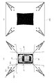
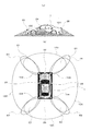
- the imaging unit 20 is installed around the vehicle as shown in FIG. 2, and the first camera 22, the second camera 24, the third camera 26, and the fourth camera are arranged so that adjacent imaging regions overlap each other.
- the third decoder 27 converts the output signal of the camera 26 into a digital signal by AD conversion
- the fourth decoder 29 converts the output signal of the fourth camera 28 into a digital signal by AD conversion.
- the virtual screen projection image generation unit 40 is created in advance based on the installation positions of the first camera 22 to the fourth camera 28 and the installation positions of the virtual screen in order to generate a virtual screen projection image.
- a first coordinate conversion data storage unit 44 storing the coordinate conversion data table, and a virtual screen for generating a virtual screen projection image based on the coordinate conversion data table stored in the first coordinate conversion data storage unit 44
- a projection image calculation unit 42 a projection image calculation unit 42.
- the road surface projection image generation unit 50 stores a coordinate conversion data table created in advance based on the installation positions of the first camera 22 to the fourth camera 28 in order to generate a road surface projection image. Based on a second coordinate conversion data storage unit 56 and a coordinate conversion data table stored in the second coordinate conversion data storage unit 56, a road surface projection image calculation unit 52 that generates a road surface projection image from an image captured by each camera. And a road surface projection image combining unit 54 that combines the plurality of generated road surface projection images into one image.
- the first viewpoint conversion unit 60 determines the virtual viewpoint position and the virtual line-of-sight direction for generating a composite image of the virtual screen projection image and the road surface projection image based on the traveling direction of the vehicle 1 and the driver's switch operation.
- a virtual viewpoint projection / virtual line-of-sight direction setting unit 66 to be set and a virtual screen projection image viewpoint conversion from the virtual viewpoint position set by the virtual viewpoint position / virtual line-of-sight direction setting unit 66 toward the virtual line-of-sight direction A third coordinate conversion data storage unit 64 in which a coordinate conversion data table is stored, and a first screen for performing viewpoint conversion of the virtual screen projection image based on the coordinate conversion data table stored in the third coordinate conversion data storage unit 64 And a viewpoint conversion calculation unit 62.
- the second viewpoint conversion unit 70 performs coordinate conversion data for performing viewpoint conversion of the road projection image from the virtual viewpoint position set by the virtual viewpoint position / virtual viewing direction setting unit 66 toward the virtual viewing direction.
- the second viewpoint conversion calculation unit 72 that converts the viewpoint of the road projection image. It consists of.
- the image synthesis unit 80 synthesizes the virtual screen projection image converted by the first viewpoint conversion unit 60 and the road surface projection image converted by the second viewpoint conversion unit 70 into one image.
- a transmittance setting unit 84 that sets the transmittance of the overlapping portion of the image, and the virtual screen projection image that has been subjected to viewpoint conversion by the first viewpoint conversion unit 60 with the transmittance set by the transmittance setting unit 84
- an image composition calculation unit 82 for compositing the road surface projection image converted by the second viewpoint conversion unit 70 with the back surface.
- the image display unit 90 specifically, an encoder 92 that converts the image synthesized by the image synthesis unit 80 from a digital signal into an analog signal, and an image that is installed in the vehicle and converted into an analog signal by the encoder 92.
- a display monitor 94 such as a liquid crystal monitor is displayed.
- the vehicle surrounding monitoring device 2 according to the first embodiment is used when a vehicle is parked or turned back in a narrow place, and presents an image around the vehicle to the driver to assist the driving operation.
- the first camera 22 is installed on the front bumper of the vehicle 1
- the second camera 24 is installed on the left door mirror of the vehicle 1
- the third camera 26 is installed on the rear bumper of the vehicle 1.
- the fourth camera 28 is installed on the right door mirror of the vehicle 1.
- each camera is installed so as to photograph a range in which the photographing range and the road surface intersect at each intersection line 120, 122, 124, 126.
- the adjacent cameras 22 and 24, 24 and 26, 26 and 28, and 28 and 22 have their shooting ranges overlapping with each other, and the first overlapping region E1 and the second overlapping region. It is installed so as to have an area E2, a third overlapping area E3, and a fourth overlapping area E4.
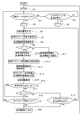
- the operation of the vehicle surrounding monitoring device 2 will be described for a scene in which the vehicle 1 is moving forward for parking.
- the driver monitors an image around the vehicle, the driver operates an activation switch 16 installed in the vehicle.
- the activation switch operation detection unit 11 detects the activation switch operation (S2 in FIG. 5), and 1 is given to the variable ⁇ representing the state of the vehicle surrounding monitoring device 2 (S4 in FIG. 5).
- Images taken by the first camera 22 to the fourth camera 28 are sampled and quantized by the first decoder 23 to the fourth decoder 29 and converted into digital images (S6 in FIG. 5). Note that images taken by the first camera 22 to the fourth camera 28 are respectively I 1 (x, y), I 2 (x, y), I 3 (x, y), and I 4 (x, y). And
- the area of each of the overlapping areas E1, E2, E3, and E4 is set to 2 in the overlapping areas E1, E2, E3, and E4 of the shooting ranges of the cameras installed adjacent to each other by the virtual screen setting unit 30.
- Flat virtual screens 200, 210, 220, and 230 that are perpendicular to the road surface and extend from the vehicle in the perspective direction are installed so as to be equally divided.
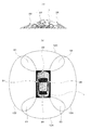
- FIG. 3 shows only the installation position of the virtual screen 200.
- the virtual screens 210, 220, and 230 are not shown, but are installed in the same positional relationship as the virtual screen 200.
- the virtual screen projection image generation unit 40 projects and converts the image I 1 (x, y) and the image I 2 (x, y) onto the first virtual screen 200 installed in the first overlap area E1, and the second overlap.
- the image I 2 (x, y) and the image I 3 (x, y) are projected and converted on the second virtual screen 210 installed in the area E2, and the third virtual screen 220 installed in the third overlapping area E3 has I 3 ( x, y) and image I 4 (x, y) are projected and converted, and I 4 (x, y) and image I 1 (x, y) are projected onto the fourth virtual screen 230 installed in the fourth overlapping region E4. Conversion is performed (S7 in FIG. 5).
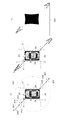
- FIG. 3 shows that the vehicle 1 and four thin columnar objects (first columnar object 301, second columnar object 302, third columnar object 303, and fourth columnar object 304) stand vertically to the road surface. It shows a state in which they are arranged at the positions of the four vertices of the square.
- the shooting ranges of the first camera 22 and the second camera 24 will be described, but the same applies to the shooting ranges of other cameras.
- the cameras 22 and 24 are installed in the horizontal direction, the first camera 22 captures the range of ⁇ XPX ′, and the second camera 24 captures the range of ⁇ YQY ′. .
- the vehicle 1 is assumed to be on a horizontal road surface.
- a flat first virtual screen 200 perpendicular to the road surface is installed at a position that divides OXOY into two equal parts.
- the first columnar object 301 and the third columnar object 303 are standing at a position overlapping the first virtual screen 200.
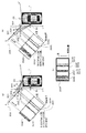
- the virtual screen projection image generation unit 40 projects the gray value of the image I 1 (x, y) photographed by the first camera 22 onto the first virtual screen 200, as shown in FIG. As illustrated in FIG. 4B, the gray value of the image I 2 (x, y) captured by the second camera 24 is projected onto the first virtual screen 200.
- Projection conversion to a virtual screen means that the image actually captured by the camera is an image of an object that originally existed on the virtual screen, and a value corresponding to the gray value of the captured image It is stored at the corresponding position on the screen.
- this projection conversion is executed as follows.
- attention is focused on the pixel (x 0 , y 0 ) constituting the image of the second columnar object 302 shown in the image I 1 (x, y).
- the grayscale value I 1 (x 0 , y 0 ) stored in the pixel (x 0 , y 0 ) is the second columnar shape of interest from the principal point position P of the first camera 22 shown in FIG.
- a half line extending toward the pixel (x 0 , y 0 ) constituting the object 302 is projected to a point intersecting the first virtual screen 200, and the gray value I 1 (x 0 , y 0 ) is stored.
- the virtual screen projection image 301P of the first columnar object 301P and the third columnar object 303 of the first columnar object 303 are displayed on the first virtual screen 200.
- a virtual screen projection image 303P and a virtual screen projection image 304P of the fourth columnar object 304 are respectively generated (see FIG. 4A).
- the virtual screen projection image 301Q of the first columnar object 301Q and the second columnar shape are displayed on the first virtual screen 200.
- a virtual screen projection image 302Q of the object 302, a virtual screen projection image 303Q of the third columnar object 303, and a virtual screen projection image 304Q of the fourth columnar object 304 are generated (see FIG. 4B).
- a first virtual screen projection image 205 shown in FIG. 4C is generated.
- the image I 1 (x, y) is used here.
- the gray value of the image I 2 (x, y) are respectively multiplied by 1/2 and added.
- the four columnar objects 301, 302, 303, and 304 stand upright on the road surface, and the first camera 22 and the second camera 24 are installed horizontally for the sake of simplicity.
- virtual screen projection images of the columnar objects 301, 302, 303, and 304 are generated in a band shape in the vertical direction of the screen.
- the four columnar objects 301, 302, 303, 304 and the vehicle 1 are in the positional relationship shown in FIG. 3, the four columnar objects 301, 302, 303, 304 are both the first camera 22, 4 and projected onto the first virtual screen 200 through the second camera 24, and as shown in FIG. 4A, four virtual screen projection images are generated as viewed from the first camera 22, and are shown in FIG. As shown, four virtual screen projection images are generated as viewed from the second camera 24.
- the virtual screen projection images are overlapped with each other, so that five virtual screen projection images are generated as shown in FIG.
- the five virtual screen projection images shown in FIG. 4C are, in order from the left, the virtual screen projection image 304P, the virtual screen projection image 302Q, the virtual screen projection images 301P and 301Q, the virtual screen projection images 303P and 303Q, and the virtual screen. These correspond to the projected images 302P and 304Q, respectively.
- the number of projected images of the virtual screen depends on the position of the columnar object and the position of the virtual screen.
- the procedure for the projection conversion to the virtual screen is performed by the virtual screen projection image calculation unit 42, and the points intersecting the first virtual screen 200 are defined as the image I 1 (x, y) and the image I 2 (x, y). Since the calculation load for each pixel is large, the image I 1 (x) projected on any pixel of the first virtual screen projection image 205 based on the arrangement of the first camera 22 and the second camera 24. , Y) and the coordinate value of the image I 2 (x, y) are calculated in advance, a coordinate conversion table is created in advance based on the calculation result, and stored in the first coordinate conversion data storage unit 44. Keep it.
- the virtual screen projection image calculation unit 42 reduces the calculation load by executing projection conversion by performing coordinate replacement based on the coordinate conversion table stored in the first coordinate conversion data storage unit 44. ing.
- Similar projection transformations are performed by the second virtual screen 210 installed in the second overlapping area E2, the third virtual screen 220 installed in the third overlapping area E3, and the fourth virtual screen 230 installed in the fourth overlapping area E4. It is also executed against. As a result, four virtual screen projection images (first virtual screen projection image 205, second virtual screen projection image 215, third virtual screen projection image 225, and fourth virtual screen projection image 235) are generated.
- the road projection image calculation unit 52 converts the images I 1 (x, y), I 2 (x, y), I 3 (x, y), and I 4 (x, y) into road surfaces, respectively. And further converted into an image looking down from directly above the vehicle (S8 in FIG. 5).
- the virtual screen projection image described above was generated on the assumption that the image captured by the camera contains an image of an object existing on the virtual screen, whereas the road surface projection image was captured by the camera.
- the generated image is an image generated on the assumption that an image of an object existing on the road surface is reflected.
- the generation of the road surface projection image is performed by the road surface projection image calculation unit 52.
- the image I 1 (x, y) specifically, from the principal point position P of the first camera 22 to the first camera 22. This is performed by obtaining a point where a half line extending toward each pixel of the photographed image I 1 (x, y) intersects the road surface.
- a road surface projection image is generated in the same manner for the image I 2 (x, y).
- the road surface projection image calculation unit 52 reduces the calculation load by executing projection conversion by replacing coordinates based on the coordinate conversion table stored in the second coordinate conversion data storage unit 56.
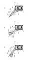
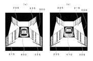
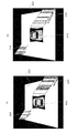
- FIG. 6 shows how the image I 1 (x, y) photographed by the first camera 22 and the image I 2 (x, y) photographed by the second camera 24 are converted into road projection images in the arrangement of FIG. Show.
- Each of 304 is converted to fall on the road projection image so as to move away from the first camera 22 along the direction connecting the principal point position P of the first camera 22 and each columnar object.
- the first columnar object 301 to the fourth columnar object 304 shown in the image I 2 (x, y) photographed by the second camera 24 are respectively on the road surface projection image. Are converted so as to fall away from the second camera 24 along the direction connecting the principal point position Q of the second camera 24 and each columnar object.
- the road projection image combining unit 54 from the image I 1 (x, y), the image I 2 (x, y), the image I 3 (x, y), and the image I 4 (x, y), respectively.
- the converted road projection image is synthesized into one image.
- the road projection image of the image I 1 (x, y) and the road projection image of the image I 2 (x, y) divide the overlapping area of the shooting range of the first camera 22 and the shooting range of the second camera 24 into two equal parts.
- the straight line AO is combined as a boundary line. That is, of the road surface projection images displayed in FIGS. 6A and 6B, an image projected across the straight line AO is not reflected in the composite image.
- the road surface projection images of the first columnar object 301 and the third columnar object 303 that exist on the straight line AO that is the joint of the road surface projection images are the portions where the columnar objects are in contact with the road surface. Disappears, leaving behind.
- a specific value is stored by replacing a gray value with a minimum value or a maximum value, and information is missing. To the driver. In this way, a combined road surface projection image 300 shown in FIG. 7B is generated.
- the four virtual screen projection images generated in S7 of FIG. 5 are converted by the first viewpoint conversion unit 60 into images observed from a predetermined viewpoint position toward a predetermined line-of-sight direction.
- the predetermined viewpoint position and the predetermined gaze direction are determined by the virtual viewpoint position / virtual gaze direction setting unit 66 based on the information detected by the operation detection unit 10.
- the virtual viewpoint is set to the rear sky of the vehicle 1, and the front side of the vehicle 1 is looked down from there.
- a virtual line-of-sight direction is set (S10 in FIG. 5).
- a coordinate conversion table for converting viewpoints as if the four virtual screen projection images were observed from the set virtual viewpoint position toward the set virtual visual line direction is stored in advance.
- the first viewpoint conversion calculation unit 62 performs viewpoint conversion based on the coordinate conversion table (S12 in FIG. 5).
- the composite road surface projection image 300 generated in S8 of FIG. 5 is directed to the same viewpoint position and the same sight line direction set by the second viewpoint conversion unit 70 in the virtual viewpoint position / virtual sight line direction setting unit 66. Converted to the observed image.
- a coordinate conversion table for converting the viewpoint of the composite road surface projection image 300 as observed from the set virtual viewpoint position toward the set virtual visual line direction. are created and stored in advance, and the viewpoint conversion is performed by the second viewpoint conversion calculation unit 72 based on the coordinate conversion table (S13 in FIG. 5).
- first virtual screen projection image 205 second virtual screen projection image 215, third virtual screen projection image 225, and fourth virtual screen
- the projection image 235) and the combined road surface projection image 300 generated by the second viewpoint conversion calculation unit 72 are virtual screen projection images (205, 215, 225, 235) on the front and the combined road surface projection image 300 on the back.
- the image composition unit 80 composes one image (S14 in FIG. 5).
- This image composition is performed by the image composition calculation unit 82 based on the transmittance determined by the transmittance setting unit 84.
- the first virtual screen projection image 205 generated by the first viewpoint conversion calculation unit 62 is K (x, y)
- the combined road surface projection image 300 generated by the second viewpoint conversion calculation unit 72 is L (x, y).
- M (x, y) is an image synthesized by the image synthesis unit 80
- M (x, y) is calculated by Equation 1.
- ⁇ is a transmittance parameter. That is, ⁇ is a value corresponding to the transmittance of the image arranged on the front surface when two images overlap, and takes a range of 0 ⁇ ⁇ ⁇ 1.
- the blacked-out areas are areas other than the virtual field projection image and the combined road surface projection image, which are in the vicinity of the position where the vehicle 1 is located and are out of the field of view of the photographing unit 20.
- a rearward first vehicle icon 400 may be superimposed and displayed at the position where the vehicle 1 is present to more clearly represent the positional relationship between the front and rear.
- the composite image of FIG. 8A obtained in this way is DA-converted by the encoder 92 and displayed on the display monitor 94 installed inside the vehicle 1 (S15 in FIG. 5).
- the vehicle speed is always detected by the vehicle speed detection unit 14, and when the detected vehicle speed exceeds a predetermined value (S16 in FIG. 5), the displayed image is returned to the state before starting the apparatus. (S20 in FIG. 5), the vehicle surrounding monitoring device 2 shifts to a non-display state (S1 in FIG. 5).
- the end switch operation detecting unit 12 detects that the end switch 18 is operated (S18 in FIG. 5)
- the displayed image is returned to the state before the activation of the apparatus (S20 in FIG. 5).
- the vehicle surroundings monitoring device 2 shifts to a non-display state (S1 in FIG. 5).
- the shift position detection unit 13 detects that the shift position is in the reverse position (S3 in FIG. 5)
- 2 is stored in the variable ⁇ representing the state of the system (S5 in FIG. 5).
- the virtual viewpoint is set in the sky above the vehicle 1, and the virtual line-of-sight direction overlooking the rear side of the vehicle 1 is set (S11 in FIG. 5).
- the virtual screen projection image and the combined road surface projection image 300 generated in the same manner as when the vehicle is moving forward are combined by the image combining calculation unit 82 and displayed as an image looking down at the rear of the vehicle as shown in FIG. Is displayed on the monitor 94 (S15 in FIG. 5).
- a forward-facing second vehicle icon 410 may be superimposed and displayed at the position where the vehicle 1 is present so that the positional relationship between the front and rear is more clearly expressed.
- the vehicle speed is constantly monitored by the vehicle speed detection unit 14, and when the vehicle speed exceeds a predetermined value (S16 in FIG. 5), it is not preferable for safety to display an image around the vehicle.
- the displayed image is returned to the state before the activation of the apparatus (S20 in FIG. 5), and the display state of the vehicle surrounding monitoring apparatus 2 is exited (S1 in FIG. 5).
- the shift position detection unit 13 always detects the shift position and detects that the shift position is other than the reverse position (S19 in FIG. 5).
- the displayed image is displayed before starting up the apparatus. (S20 in FIG. 5), the display state of the vehicle surrounding monitoring device 2 is exited (S1 in FIG. 5).
- the vehicle surrounding monitoring apparatus 2 even if a three-dimensional object exists in the boundary part of the shooting range of adjacent cameras, a virtual screen is installed in the boundary part, By generating a projection image on the virtual screen and displaying the projection image, the three-dimensional object can be accurately displayed without causing a blind spot. Therefore, the situation around the vehicle can be accurately transmitted to the driver, and thereby vehicle guidance such as parking operation and turn-back operation can be performed smoothly.
- the virtual screen projection image and the combined road surface projection image are combined and displayed, but the format is not limited. That is, only the virtual screen projection image may be displayed as shown in FIG.
- the display method of FIG. 9 it is possible to accurately display the state of obstacles in the vicinity of the vehicle in the vicinity of the joint of the image in which the blind spot is generated.
- the four virtual screen projection images and the combined road surface projection image are combined and displayed on one image, but the format is not limited. That is, when the vehicle moves forward, only the first virtual screen projection image 205, the fourth virtual screen projection image 235, and the combined road surface projection image 300 may be combined and displayed in FIG. This is because, when the virtual viewpoint position and the virtual viewpoint direction are set by the virtual viewpoint position / virtual line-of-sight direction setting unit 66, the first virtual screen projection image 205 and the fourth virtual screen are stored in the third coordinate conversion data storage unit 64. This can be realized by giving an instruction to create only the screen projection image 235.
- the second virtual screen projection image 215, the third virtual screen projection image 225, and the combined road surface projection image 300 may be combined and displayed in FIG. 8B.
- the second virtual screen projection image 215 and the third virtual screen are output to the third coordinate conversion data storage unit 64.
- This can be realized by giving an instruction to create only the screen projection image 225.
- the present invention is applied to a vehicle surrounding monitoring device 4 that can display the situation around the vehicle photographed by a plurality of cameras installed in the vehicle in a form that is easy to see for the driver. is there.
- the second embodiment includes an obstacle detection unit around the vehicle. Based on the output of the obstacle detection unit, an image around the vehicle is converted into a more easily understood form and displayed on a monitor installed in the vehicle. To do.
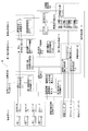
- FIG. 10 is a block diagram showing a configuration of the vehicle surrounding monitoring device 4 according to the second embodiment of the present invention.
- the vehicle surrounding monitoring device 4 is installed in a vehicle 1 (not shown), and an operation detection unit 10 that detects a start operation and an end operation of the vehicle surrounding monitoring device 4 by a driver, An operation switch 15 that is installed within the reach of the driver and that instructs activation and termination of the vehicle surroundings monitoring device 4, an imaging unit 20 that includes a plurality of cameras that capture images around the vehicle, and an imaging unit
- the virtual screen setting unit 30 that sets a virtual screen in an overlapping portion of the shooting areas of adjacent cameras among the plurality of cameras that constitute the image 20, and the virtual screen set by the virtual screen setting unit 30 shoots with the adjacent camera
- a virtual screen projection image generation unit 40 that projects each of the images generated to generate a virtual screen projection image, and projects a captured image of the surroundings of the vehicle onto the road surface to project the road surface
- a road surface projection image generation unit 50 that generates an image and a virtual screen projection image generated by the virtual screen projection image generation unit 40 are converted into an image captured from a predetermined virtual viewpoint toward a predetermined virtual
- An image synthesis unit 80 that synthesizes the virtual screen projection image converted by the first viewpoint conversion unit 60 and the road surface projection image converted by the second viewpoint conversion unit 70 into a single image;
- the image display unit 90 displays a synthesized image, and the obstacle detection unit 100 detects the presence or absence of an obstacle around the vehicle 1 and calculates the distance to the obstacle.
- the operation detection unit 10 includes a start switch operation detection unit 11 that detects a driver's start operation of the vehicle surroundings monitoring device 4 and an end switch operation detection unit 12 that detects an end operation of the vehicle surroundings monitoring device 4. And a shift position detector 13 for detecting the shift position of the vehicle and a vehicle speed detector 14 for detecting the vehicle speed.
- the operation switch 15 includes an activation switch 16 for instructing activation of the vehicle surrounding monitoring device 4 and an end switch 18 for instructing termination of the vehicle surrounding monitoring device 4.
- the imaging unit 20 is installed around the vehicle as shown in FIG. 11, and the first camera 22, the second camera 24, the third camera 26, and the fourth camera are arranged so that adjacent imaging regions overlap each other.
- the third decoder 27 converts the output signal of the camera 26 into a digital signal by AD conversion
- the fourth decoder 29 converts the output signal of the fourth camera 28 into a digital signal by AD conversion.
- the virtual screen projection image generation unit 40 is created in advance based on the installation positions of the first camera 22 to the fourth camera 28 and the installation positions of the virtual screen in order to generate a virtual screen projection image.
- a first coordinate conversion data storage unit 44 storing the coordinate conversion data table, and a virtual screen for generating a virtual screen projection image based on the coordinate conversion data table stored in the first coordinate conversion data storage unit 44
- a projection image calculation unit 42 a projection image calculation unit 42.
- the road surface projection image generation unit 50 stores a coordinate conversion data table created in advance based on the installation positions of the first camera 22 to the fourth camera 28 in order to generate a road surface projection image. Based on the coordinate conversion data table stored in the second coordinate conversion data storage unit 56 and the second coordinate conversion data storage unit 56, a road surface projection image calculation unit that generates a road surface projection image from an image captured by each camera. 52 and a road surface projection image combining unit 54 that combines the plurality of generated road surface projection images into one image.
- the first viewpoint conversion unit 60 generates a composite image of the virtual screen projection image and the road surface projection image based on the traveling direction of the vehicle 1 and the driver's switch operation.
- a virtual viewpoint projection / virtual line-of-sight direction setting unit 66 to be set and a virtual screen projection image viewpoint conversion from the virtual viewpoint position set by the virtual viewpoint position / virtual line-of-sight direction setting unit 66 toward the virtual line-of-sight direction A third coordinate conversion data storage unit 64 in which a coordinate conversion data table is stored, and a first screen for performing viewpoint conversion of the virtual screen projection image based on the coordinate conversion data table stored in the third coordinate conversion data storage unit 64 And a viewpoint conversion calculation unit 62.
- the second viewpoint conversion unit 70 performs coordinate conversion data for performing viewpoint conversion of the road projection image from the virtual viewpoint position set by the virtual viewpoint position / virtual viewing direction setting unit 66 toward the virtual viewing direction.
- the second viewpoint conversion calculation unit 72 that converts the viewpoint of the road projection image. It consists of.
- the image synthesis unit 80 synthesizes the virtual screen projection image converted by the first viewpoint conversion unit 60 and the road surface projection image converted by the second viewpoint conversion unit 70 into one image.
- a transmittance setting unit 84 that sets the transmittance of the overlapping portion of the image, and the virtual screen projection image that has been subjected to viewpoint conversion by the first viewpoint conversion unit 60 with the transmittance set by the transmittance setting unit 84
- an image composition calculation unit 82 for compositing the road surface projection image converted by the second viewpoint conversion unit 70 with the back surface.
- the image display unit 90 includes an encoder 92 that converts the image synthesized by the image synthesis unit 80 from a digital signal into an analog signal, and a display monitor 94 that displays an image converted into an analog signal by the encoder 92. Consists of.
- the obstacle detection unit 100 is specifically installed around the vehicle 1 as shown in FIG. 11, and is a first overlapping region E1 that is an overlapping range of the shooting range of the first camera 22 and the shooting range of the second camera 24.
- the first distance measurement unit 102 for calculating the presence / absence of an obstacle in the first distance measurement range R1 including the distance to the obstacle, the overlapping range of the shooting range of the second camera 24 and the shooting range of the third camera 26
- the second distance measuring unit 104 that calculates the presence / absence of an obstacle in the second distance measurement range R2 including a certain second overlapping area E2 and the distance to the obstacle, the photographing range of the third camera 26, and the fourth camera 28
- the third ranging unit 106 that calculates the presence / absence of an obstacle in the third ranging range R3 including the third overlapping area E3 that is the overlapping range of the imaging range and the distance to the obstacle, and the imaging range of the fourth camera 28 And the fourth overlapping area, which is the overlapping range of the shooting range of the first camera 22
- the vehicle periphery monitoring device 4 according to the present invention is used when a vehicle is parked or turned back in a narrow place, and assists driving operation by presenting an image around the vehicle to the driver.
- the first camera 22 is installed on the front bumper of the vehicle 1
- the second camera 24 is installed on the left door mirror of the vehicle 1
- the third camera 26 is installed on the rear bumper of the vehicle 1.
- the fourth camera 28 is installed on the right door mirror of the vehicle 1.
- the first distance measuring section 102 is on the front bumper left corner
- the second distance measuring section 104 is on the rear bumper left corner
- the third distance measuring section 106 is on the rear bumper right corner.
- the distance measuring unit 108 is installed at the right corner of the front bumper.
- These distance measuring units are specifically composed of an ultrasonic sensor or an optical distance measuring sensor, but the structure is not limited as long as it has a distance measuring function.
- each camera is installed so as to photograph a range in which the photographing range and the road surface intersect at each intersection line 120, 122, 124, 126.
- the adjacent cameras 22 and 24, 24 and 26, 26 and 28, and 28 and 22 have overlapping shooting ranges, and the first overlap region E1 and the second overlap. It is installed so as to have an area E2, a third overlapping area E3, and a fourth overlapping area E4.
- the first distance measuring unit 102 sets the area including the first overlapping area E1 as the first distance measuring range R1
- the second distance measuring section 104 sets the area including the second overlapping area E2 as the second distance measuring range R2.
- the third ranging unit 106 sets the area including the third overlapping area E3 as the third ranging range R3
- the fourth ranging unit 108 sets the area including the fourth overlapping area E4 as the fourth ranging range R4. It is arranged so that.
- the operation of the second embodiment will be described with respect to a scene in which the vehicle 1 moves forward at a slow speed for parking.
- the driver monitors the surroundings of the vehicle, the driver operates the start switch 16 installed in the vehicle.
- the activation switch operation detection unit 11 detects the activation switch operation (S2 in FIG. 12).
- 1 is given to the variable ⁇ representing the state of the vehicle surrounding monitoring device 4 (S4 in FIG. 12).
- Images captured by the first camera 22 to the fourth camera 28 are sampled and quantized by the first decoder 23 to the fourth decoder 29 and converted into digital images (S6 in FIG. 12). Note that an image captured by the first camera 22 is I 1 (x, y), an image captured by the second camera 24 is I 2 (x, y), and an image captured by the third camera 26 is I 3. (X, y), and an image taken by the fourth camera 28 is I 4 (x, y).
- the first distance measuring section 102 to the fourth distance measuring section 108 measure the distance around the vehicle, and correspond to the distance from each distance measuring section to the obstacle around the vehicle 1. Is output.
- the four columnar objects on the left front side of the vehicle are inside the attention-requiring area 420 that requires attention when performing the parking operation, and the four columnar objects on the right rear side of the vehicle are the attention-requiring area 420. It shall be outside of
- a smaller value corresponding to the distance is output as the distance from the road surface to the object (obstacle) having a height is shorter.
- the smallest value is output from the first distance measuring unit 102, and the next smallest value is output from the third distance measuring unit 106. Since there are no obstacles on the left rear and right front of the vehicle 1, the second distance measuring unit 104 and the fourth distance measuring unit 108 output very large values indicating that no obstacle exists. .
- the values output from the four distance measuring units are sent to the distance value determining unit 109, and the presence / absence and the position of the distance measuring unit that outputs a value equal to or less than a predetermined value are determined. Identified. In the case of this example, it is specified that a value equal to or smaller than a predetermined value is output from the first distance measuring unit 102 (S7 in FIG. 12).
- the virtual screen installation unit 30 installs the first virtual screen 200 that is planar and perpendicular to the road surface extending in the perspective direction from the vehicle so that the area of the first overlapping region E1 is divided into two equal parts. .
- the virtual screen projection image generation unit 40 projects and converts the image I 1 (x, y) and the image I 2 (x, y) on the first virtual screen 200 that is installed, thereby generating a virtual screen projection image. (S8 in FIG. 12). Since the generation method of the virtual screen projection image is as described in the first embodiment, the description is omitted here.
- the virtual screen projection image is generated by the virtual screen projection image calculation unit 42, and a point intersecting the first virtual screen 200 is determined for each pixel of the image I 1 (x, y) and the image I 2 (x, y). Since the calculation load is large, the image I 1 (x, y) projected on an arbitrary pixel of the first virtual screen projection image 205 based on the arrangement of the first camera 22 and the second camera 24 is calculated. ) And image I 2 (x, y) are calculated in advance, a coordinate conversion table is created in advance based on the calculation result, and stored in the first coordinate conversion data storage unit 44. .
- the virtual screen projection image calculation unit 42 reduces the calculation load by performing projection conversion by performing coordinate replacement operation based on the coordinate conversion table stored in the first coordinate conversion data storage unit 44. is doing. By this projection conversion, a first virtual screen projection image 205 is generated.
- the road projection image calculation unit 52 converts the images I 1 (x, y), I 2 (x, y), I 3 (x, y), and I 4 (x, y) into road surfaces, respectively. And further converted into an image looking down from directly above the vehicle (S9 in FIG. 12).
- the road surface projection image is generated by the road surface projection image calculation unit 52.
- the first camera 22 captures the image from the principal point position P of the first camera 22.
- the half line extending toward each pixel of the image I 1 (x, y) is obtained by obtaining a point where the road surface intersects.
- a road surface projection image is generated in the same manner for the image I 2 (x, y).
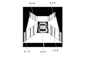
- FIG. 13A When the environment in which the second embodiment is operating is FIG. 13A, road surface projection images of four images taken by four cameras are synthesized as shown in FIG. 13B.
- a specific value is stored by replacing a gray value with a minimum value or a maximum value, and information is missing. Let the driver know. In this way, a composite road surface projection image 300 shown in FIG. 13C is generated.
- the first virtual screen projection image 205 generated in S8 of FIG. 12 is converted by the first viewpoint conversion unit 60 into an image observed from a predetermined viewpoint position toward a predetermined visual line direction.
- the predetermined viewpoint position and the predetermined gaze direction are determined by the virtual viewpoint position / virtual gaze direction setting unit 66 based on the information detected by the operation detection unit 10.
- the virtual viewpoint is set to the rear sky of the vehicle 1, and the front side of the vehicle 1 is looked down from there.
- a virtual line-of-sight direction is set (S11 in FIG. 12).
- the third coordinate conversion data storage unit 64 a coordinate conversion table for converting the viewpoint as if the virtual screen projection image was observed from the set virtual viewpoint position toward the set virtual visual line direction is created in advance. Based on the stored coordinate conversion table, the first viewpoint conversion calculation unit 62 performs viewpoint conversion (S13 in FIG. 12).
- the composite road surface projection image 300 generated in S9 of FIG. 12 is directed to the same line-of-sight direction from the same viewpoint position set by the virtual viewpoint position / virtual line-of-sight direction setting unit 66 by the second viewpoint conversion unit 70. Converted to the observed image.
- the fourth coordinate conversion data storage unit 74 includes a coordinate conversion table for performing viewpoint conversion so that the synthesized road surface projection image 300 is observed from the set virtual viewpoint position toward the set virtual visual line direction.
- the viewpoint conversion is performed by the second viewpoint conversion calculation unit 72 based on the coordinate conversion table (S14 in FIG. 12).
- the first virtual screen projection image 205 generated by the first viewpoint conversion calculation unit 62 and the composite road surface projection image 300 generated by the second viewpoint conversion calculation unit 72 are the first virtual screen projection image 205.
- the synthesized road surface projection image 300 is placed on the front side and the image is synthesized by the image synthesis unit 80 (S15 in FIG. 12).
- This image composition is performed by the image composition calculation unit 82 based on the rule determined by the transmittance setting unit 84.
- the first virtual screen projection image 205 generated by the first viewpoint conversion calculation unit 62 is K (x, y)
- the combined road surface projection image 300 generated by the second viewpoint conversion calculation unit 72 is L (x, y).
- M (x, y) is an image synthesized by the image synthesizing unit 80
- M (x, y) is calculated by Equation 1 described above.
- the transmittance parameter ⁇ takes a value in the range of 0 ⁇ ⁇ ⁇ 1.
- ⁇ 1 is set. This is a setting in which when the virtual screen projection image (205, 215, 225, 235) and the combined road surface projection image 300 overlap, the combined road surface projection image 300 combined on the back surface is made invisible.
- the blacked-out areas are areas other than the virtual field projection image and the combined road surface projection image, which are in the vicinity of the position where the vehicle 1 is located and are out of the field of view of the photographing unit 20.
- a rearward first vehicle icon 400 may be superimposed and displayed at the position where the vehicle 1 is present to more clearly represent the front-rear positional relationship.
- the synthesized image of FIG. 14A obtained in this way is DA-converted by the encoder 92 and displayed on the display monitor 94 installed inside the vehicle 1 (S16 in FIG. 12).
- the vehicle speed is always detected by the vehicle speed detection unit 14, and when the detected vehicle speed exceeds a predetermined value (S17 in FIG. 12), the displayed image is returned to the state before the activation of the apparatus. (S21 in FIG. 12), the vehicle periphery monitoring device 4 shifts to a non-display state (S1 in FIG. 12).
- the end switch operation detection unit 12 detects that the end switch 18 has been operated (S19 in FIG. 12)
- the displayed image is returned to the state before the activation of the apparatus (S21 in FIG. 12).
- the vehicle periphery monitoring device 4 shifts to a non-display state (S1 in FIG. 12).
- the shift position detection unit 13 detects that the shift position is in the reverse position (S3 in FIG. 12)
- 2 is stored in the variable ⁇ representing the state of the system (S5 in FIG. 12).
- the virtual viewpoint is set in the sky above the vehicle 1, and the virtual line-of-sight direction overlooking the rear side of the vehicle 1 is set (S12 in FIG. 12).
- the virtual screen projection image and the combined road surface projection image 300 generated in the same manner as when the vehicle is moving forward are combined by the image combining calculation unit 82 and displayed as an image looking down at the rear of the vehicle as shown in FIG. Is displayed on the monitor 94 (S16 in FIG. 12).
- a forward-facing second vehicle icon 410 may be superimposed and displayed at the position where the vehicle 1 is present so that the positional relationship between the front and rear is more clearly expressed.
- the vehicle speed is always detected by the vehicle speed detection unit 14, and when the detected vehicle speed exceeds a predetermined value (S17 in FIG. 12), the displayed image is returned to the state before starting the apparatus. (S21 in FIG. 12), the vehicle periphery monitoring device 4 shifts to a non-display state (S1 in FIG. 12).
- the shift position detection unit 13 If the shift position is always detected by the shift position detection unit 13 and it is detected that the shift position is other than the reverse position (S20 in FIG. 12), the displayed image is displayed before starting the apparatus. (S21 in FIG. 12), the vehicle surroundings monitoring device 4 shifts to a non-display state (S1 in FIG. 12).
- a virtual screen is installed only in an area where an obstacle is detected, and a virtual screen projection image is generated for the virtual screen.
- the virtual screen projection image is displayed only when there is an obstacle at the joint position of the image that becomes a blind spot. The property can be further improved.
- a virtual screen is installed at a location corresponding to the area where the obstacle is detected.
- the composite image is generated with the composite road surface projection image 300 overlapping the virtual screen projection image generated by projecting on the virtual screen being made invisible, but the format is not limited.
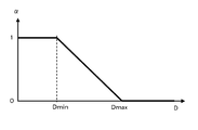
- the transmittance parameter ⁇ is set to 1 to make the combined road surface projection image 300 invisible, and further, Dmin ⁇
- Di ⁇ Dmax the smaller the value Di corresponding to the distance, the more transparent
- the distance value determination unit 109 observes the time change of the values D1 to D4 corresponding to the distances from the first distance measurement unit 102 to the obstacles output from each of the fourth distance measurement units 108, and each Di.
- a planar virtual screen perpendicular to the road surface extending in the perspective direction from the vehicle is installed at a position that bisects the area of the overlapping area of the shooting ranges of adjacent cameras. You will not be trapped by.
- the distance measuring unit (102, 104, 106, 108) has a function of measuring distance information for each angle in the horizontal direction by scanning the distance measuring range in the horizontal direction (vehicle peripheral direction), and obstructing the obstacle.
- a planar virtual screen extending vertically from the road surface extending in the direction in which information is obtained may be installed, and a virtual screen projection image may be generated and displayed on the virtual screen.
- the obstacle image in the virtual screen projection image is virtualized from two adjacent cameras that photograph the obstacle. Projected to the same position on the screen, therefore, on the virtual screen projection image, the shade value of the image representing the obstacle is added to a larger value, thereby displaying the obstacle more clearly and improving the visibility of the image. The effect of improving is acquired.
Abstract
A virtual screen setup unit (30) sets up, in the seams of images taken by an imaging unit (20), a virtual screen perpendicular to the road surface and extending in the near-to-far direction relative to the vehicle; a virtual screen projection image generation unit (40) transforms the images captured by the imaging unit (20) for projection onto the virtual screen, and generates a virtual screen projection image which is displayed by an image display unit (90).
Description
本発明は、車両に設置され、車両の周囲を撮影した画像を表示する車両用周囲監視装置に関する。詳細には、車両の周囲に障害物が存在したとき、その障害物の存在を的確に表示することができる車両用周囲監視装置に関する。
The present invention relates to a vehicle surrounding monitoring device that is installed in a vehicle and displays an image of the surroundings of the vehicle. More specifically, the present invention relates to a vehicle surrounding monitoring device that can accurately display the presence of an obstacle when there is an obstacle around the vehicle.
近年、車両にカメラを設置し、運転者に対して死角になりやすい車両周辺の画像を撮影して表示するシステムが一般的になってきている。
In recent years, a system in which a camera is installed in a vehicle to capture and display an image around the vehicle that is likely to be a blind spot for a driver has become common.
特に、最近では、車両に複数のカメラを設置し、真上から見下ろしたように座標変換して俯瞰画像を生成し、さらに、生成した俯瞰画像同士を合成して、車両の周囲360°を見渡した画像を表示するシステムも実用化されている。
In particular, recently, a plurality of cameras are installed in a vehicle, coordinate conversion is performed as if looking down from directly above, and an overhead image is generated, and the generated overhead images are synthesized to look around 360 ° around the vehicle. A system for displaying a captured image has also been put into practical use.
その中には、例えば、俯瞰画像同士を合成する際、画像の繋ぎ目の位置を、車両の挙動に基づいて設定する発明が提案されている(特許文献1)。
Among them, for example, when synthesizing overhead images, an invention has been proposed in which the position of the joint of the images is set based on the behavior of the vehicle (Patent Document 1).
しかしながら、特許文献1に開示された発明では、高さのある物体を路面に投影変換して画像化しているため、路面から高さのある物体は、変換後の画像では歪んでしまい、これによって立体物が認知しにくくなるという課題がある。
However, in the invention disclosed in Patent Document 1, since an object having a height is projected and converted onto a road surface, the object having a height from the road surface is distorted in the image after conversion. There is a problem that a three-dimensional object becomes difficult to recognize.
また、異なるカメラで撮影した画像同士の、ちょうど繋ぎ目の位置に細い柱状物(立体物)が直立していたとき、撮影された画像を路面に投影変換すると、この柱状物は、その柱状物を撮影するカメラの主点位置と柱状物とを結ぶ方向に、カメラから遠ざかる向きに倒れ込んで変換される。したがって、繋ぎ目の位置で画像を合成すると、その繋ぎ目の位置を越えて倒れ込んだ柱状物の変換像が切り取られてしまい、結果的に、画像の繋ぎ目の位置にある柱状物の変換像は、路面と接している部分のみしか残らず、すなわち、合成された俯瞰画像上では、その繋ぎ目において、路面から高さを有する物体に対して死角が生じてしまうという課題がある。
In addition, when a thin columnar object (three-dimensional object) stands upright at the joint position between images taken with different cameras, this columnar object is converted into a columnar object by projecting the captured image onto the road surface. The camera falls into the direction connecting the principal point position of the camera and the columnar object so as to move away from the camera. Therefore, when the image is synthesized at the joint position, the converted image of the columnar object that falls over the joint position is cut out, and as a result, the converted image of the columnar object at the joint position of the image. Has a problem that only a portion in contact with the road surface remains, that is, on the synthesized overhead image, a blind spot is generated at the joint with respect to an object having a height from the road surface.
本発明は上記事情に鑑みなされたもので、画像同士の繋ぎ目においても、死角を生じることなく、路面から高さのある立体物を、歪みなく的確に表示することができる車両用周囲監視装置を提供することを目的とする。
SUMMARY OF THE INVENTION The present invention has been made in view of the above circumstances, and a vehicle surrounding monitoring device capable of accurately displaying a three-dimensional object having a height from a road surface without distortion even at a joint between images without causing a blind spot. The purpose is to provide.
本発明に係る車両用周囲監視装置は、車両の周囲に取り付けられ、隣り合う撮影範囲の一部が重複するように配置された複数の撮影部の重複領域の中に、仮想スクリーン設置部が前記車両に対して遠近方向に延びた仮想スクリーンを設置し、仮想スクリーン投影画像生成部が、隣り合う前記撮影部で撮影した各々の画像を、前記仮想スクリーンに投影して仮想スクリーン投影画像を生成し、第1視点変換部が、仮想スクリーン投影画像を所定の視点位置から所定の視線方向を向いて観測した画像に座標変換して、画像表示部が前記座標変換された画像を表示するものである。
The vehicle periphery monitoring device according to the present invention is attached to the periphery of the vehicle, and the virtual screen installation unit is included in an overlapping region of a plurality of imaging units arranged so that a part of adjacent imaging ranges overlaps. A virtual screen extending in a perspective direction with respect to the vehicle is installed, and a virtual screen projection image generation unit generates a virtual screen projection image by projecting each image captured by the adjacent imaging unit onto the virtual screen. The first viewpoint conversion unit converts the virtual screen projection image into an image observed from a predetermined viewpoint position in a predetermined line-of-sight direction, and the image display unit displays the coordinate-converted image. .
すなわち、本発明に係る第1の車両用周囲監視装置は、車両周囲を撮影するように、隣り合う撮影範囲の一部が重複領域を有して車両に設置された複数の撮影部と、前記撮影範囲の重複領域の内部に、前記車両に対して遠近方向に延び、路面から鉛直方向に立ち上がった仮想スクリーンを設置する仮想スクリーン設置部と、隣り合う前記撮影部で撮影した各々の画像の各画素に格納された濃淡値に対応する値を、前記撮影部の各々の主点に対応する位置から前記撮影部で撮影された画像の各画素に向かって延ばした半直線が前記仮想スクリーンと交差する位置に格納する仮想スクリーン投影画像生成部と、前記仮想スクリーン投影画像生成部によって生成された画像を、所定の視点位置から所定の視線方向を向いて観測した画像に座標変換して出力する第1視点変換部と、前記第1視点変換部から出力された画像を表示する画像表示部とを備えたことを特徴とする。
That is, the first vehicle surrounding monitoring apparatus according to the present invention includes a plurality of photographing units installed in a vehicle with a part of an adjacent photographing range having an overlapping region so as to photograph the surroundings of the vehicle, Inside the overlapping area of the shooting range, each of each of the images shot by the virtual screen setting unit that sets a virtual screen extending in the perspective direction with respect to the vehicle and rising in the vertical direction from the road surface, and the adjacent shooting unit A half line extending from the position corresponding to each principal point of the photographing unit toward each pixel of the image photographed by the photographing unit intersects with the virtual screen. A virtual screen projection image generation unit stored at a position to be coordinated, and coordinate conversion of the image generated by the virtual screen projection image generation unit into an image observed from a predetermined viewpoint position toward a predetermined gaze direction A first viewpoint conversion unit for outputting Te, characterized in that an image display unit which displays the image output from the first viewpoint conversion unit.
このように構成された本発明に係る第1の車両用周囲監視装置によれば、仮想スクリーン設置部が、隣り合う撮影部の各々の撮影範囲の重複領域の中に、車両に対して遠近方向に延びた仮想スクリーンを設置し、仮想スクリーン投影画像生成部が隣り合う前記撮影部で撮影した各々の画像の濃淡値に対応した値を前記仮想スクリーンに投影して仮想スクリーン投影画像を生成し、こうして生成された仮想スクリーン投影画像を、画像表示部によって表示することにより、画像同士の繋ぎ目においても、死角を生じることなく、路面から高さのある立体物を、歪みなく的確に表示することができる。
According to the first vehicle periphery monitoring device according to the present invention configured as described above, the virtual screen installation unit is in the perspective direction with respect to the vehicle in the overlapping region of the shooting ranges of the adjacent shooting units. A virtual screen projection image generation unit projects a value corresponding to the gray value of each image captured by the imaging unit adjacent to the virtual screen to generate a virtual screen projection image, By displaying the virtual screen projection image generated in this way by the image display unit, it is possible to accurately display a three-dimensional object having a height from the road surface without causing a blind spot even at the joint between the images. Can do.
また、本発明に係る第2の車両用周囲監視装置は、車両周囲を撮影するように、隣り合う撮影範囲の一部が重複領域を有して車両に設置された複数の撮影部と、前記撮影範囲の重複領域の内部に、前記車両に対して遠近方向に延び、路面から鉛直方向に立ち上がった仮想スクリーンを設置する仮想スクリーン設置部と、隣り合う前記撮影部で撮影した各々の画像の各画素に格納された濃淡値に対応する値を、前記撮影部の各々の主点に対応する位置から前記撮影部で撮影された画像の各画素に向かって延ばした半直線が前記仮想スクリーンと交差する位置に格納する仮想スクリーン投影画像生成部と、前記仮想スクリーン投影画像生成部によって生成された画像を、所定の視点位置から所定の視線方向を向いて観測した画像に座標変換して出力する第1視点変換部と、前記複数の撮影部で撮影した各々の画像の各画素に格納された濃淡値を、前記撮影部の各々の主点に対応する位置から前記撮影部で撮影された画像の各画素に向かって延ばした半直線が路面と交差する位置に格納する路面投影画像生成部と、前記路面投影画像生成部によって生成された画像を、前記所定の視点位置から、前記所定の視線方向を向いて観測した画像に座標変換して出力する第2視点変換部と、前記第1視点変換部から出力された画像と、前記第2視点変換部から出力された画像とを、1枚の画像に合成して出力する画像合成部と、前記画像合成部から出力された画像を表示する画像表示部とを備えたことを特徴とする。
In addition, the second vehicle surrounding monitoring device according to the present invention includes a plurality of photographing units installed in a vehicle with a part of an adjacent photographing range having an overlapping region so as to photograph the surroundings of the vehicle, Inside the overlapping area of the shooting range, each of each of the images shot by the virtual screen setting unit that sets a virtual screen extending in the perspective direction with respect to the vehicle and rising in the vertical direction from the road surface, and the adjacent shooting unit A half line extending from the position corresponding to each principal point of the photographing unit toward each pixel of the image photographed by the photographing unit intersects with the virtual screen. A virtual screen projection image generation unit stored at a position to be coordinated, and an image generated by the virtual screen projection image generation unit is coordinate-transformed into an image observed from a predetermined viewpoint position toward a predetermined line-of-sight direction The first viewpoint conversion unit to be operated, and the gray value stored in each pixel of each image photographed by the plurality of photographing units are photographed by the photographing unit from a position corresponding to each principal point of the photographing unit. A road projection image generation unit storing a half line extending toward each pixel of the image at a position intersecting the road surface; and an image generated by the road projection image generation unit from the predetermined viewpoint position, A second viewpoint conversion unit that converts and outputs an image observed in the direction of the line of sight, an image output from the first viewpoint conversion unit, and an image output from the second viewpoint conversion unit, An image composition unit that composes and outputs a single image and an image display unit that displays the image outputted from the image composition unit are provided.
このように構成された本発明に係る第2の車両用周囲監視装置によれば、仮想スクリーン設置部が、隣り合う撮影部の各々の撮影範囲の重複領域の中に、車両に対して遠近方向に延びた仮想スクリーンを設置し、仮想スクリーン投影画像生成部が隣り合う前記撮影部で撮影した各々の画像の濃淡値に対応した値を前記仮想スクリーンに投影して仮想スクリーン投影画像を生成するとともに、路面投影画像生成部が、前記複数の撮影部で撮影した各々の画像の各画素に格納された濃淡値を路面に投影して路面投影画像を生成し、こうして生成された仮想スクリーン投影画像と路面投影画像とを、画像合成部によって1枚の画像に合成して、画像表示部によって表示することにより、隣り合う撮影範囲の境界部分のみならず、車両周囲に存在する立体物をも、的確に表示することができる。
According to the second vehicle periphery monitoring device according to the present invention configured as described above, the virtual screen installation unit is in the perspective direction with respect to the vehicle in the overlapping region of the shooting ranges of the adjacent shooting units. And a virtual screen projection image generator generates a virtual screen projection image by projecting a value corresponding to the gray value of each image captured by the imaging unit adjacent to the virtual screen onto the virtual screen. The road surface projection image generation unit generates a road surface projection image by projecting the gray value stored in each pixel of each image captured by the plurality of image capturing units onto the road surface, and the virtual screen projection image thus generated and By combining the road projection image with a single image by the image composition unit and displaying the image by the image display unit, the image is present not only at the boundary between adjacent shooting ranges but also around the vehicle. Also three-dimensional object can be accurately displayed.
本発明に係る車両用周囲監視装置によれば、車両周囲に設置された複数の撮影部で撮影した画像の繋ぎ目に存在する、路面から高さのある立体物を、歪みなく的確に表示することができ、これによって、表示された画像を頼りに、車両の駐車操作や切り返し操作を、円滑に行うことができるようになるという効果が得られる。
According to the vehicle surrounding monitoring apparatus according to the present invention, a three-dimensional object having a height from the road surface that is present at the joint of images taken by a plurality of photographing units installed around the vehicle is accurately displayed without distortion. Thus, the vehicle can be smoothly parked or turned back on the basis of the displayed image.
以下、本発明に係る車両用周囲監視装置の実施例について、図面を参照して説明する。
Embodiments of a vehicle surrounding monitoring apparatus according to the present invention will be described below with reference to the drawings.
実施例1は、本発明を、車両に設置された複数のカメラで撮影した車両周囲の画像を、運転者に見やすい形態で表示することが可能な、車両用周囲監視装置2に適用したものである。
In the first embodiment, the present invention is applied to a vehicle surrounding monitoring device 2 capable of displaying images around a vehicle photographed by a plurality of cameras installed in the vehicle in a form that is easy for the driver to see. is there.
図1は、本発明の実施例1に係る車両用周囲監視装置2の構成を示すブロック図である。実施例1に係る車両用周囲監視装置2は、図1に示す通り、図示しない車両1に設置され、運転者による車両用周囲監視装置2の起動操作や終了操作を検出する操作検出部10と、運転者の手の届く範囲に設置され、車両用周囲監視装置2の起動や終了を指示する操作スイッチ15と、車両周囲の画像を撮影する複数のカメラから構成された撮影部20と、撮影部20を構成する複数のカメラのうち、隣り合うカメラの撮影領域の重複部に仮想スクリーンを設置する仮想スクリーン設置部30と、仮想スクリーン設置部30で設置した仮想スクリーンに、前記隣り合うカメラで撮影した各々の画像を投影して仮想スクリーン投影画像を生成する仮想スクリーン投影画像生成部40と、撮影された車両周囲の画像を、路面に投影して路面投影画像を生成する路面投影画像生成部50と、仮想スクリーン投影画像生成部40で生成された仮想スクリーン投影画像を、所定の仮想視点から所定の仮想視線方向を向いて観測した画像に変換する第1視点変換部60と、路面投影画像生成部50で生成された路面投影画像を、前記所定の仮想視点から前記所定の仮想視線方向を向いて観測した画像に変換する第2視点変換部70と、第1視点変換部60によって視点変換された仮想スクリーン投影画像と第2視点変換部70によって視点変換された路面投影画像を1枚の画像に合成する画像合成部80と、画像合成部80で合成した画像を表示する画像表示部90とから構成される。
FIG. 1 is a block diagram illustrating a configuration of a vehicle surrounding monitoring device 2 according to a first embodiment of the present invention. As shown in FIG. 1, the vehicle surrounding monitoring device 2 according to the first embodiment is installed in a vehicle 1 (not shown), and an operation detection unit 10 that detects a start operation and an end operation of the vehicle surrounding monitoring device 2 by a driver. An operation switch 15 that is installed within the reach of the driver and that instructs activation and termination of the vehicle surroundings monitoring device 2, an imaging unit 20 that includes a plurality of cameras that capture images around the vehicle, Among the plurality of cameras constituting the unit 20, the virtual screen installation unit 30 that installs a virtual screen in the overlapping part of the shooting areas of adjacent cameras, and the virtual screen installed by the virtual screen installation unit 30, the adjacent camera A virtual screen projection image generation unit 40 that projects each captured image to generate a virtual screen projection image, and projects a captured image around the vehicle onto a road surface to project a road surface projection image. The first viewpoint that converts the virtual screen projection image generated by the road surface projection image generation unit 50 and the virtual screen projection image generation unit 40 that are generated from the predetermined virtual viewpoint into the image observed in the predetermined virtual line-of-sight direction. A conversion unit 60; a second viewpoint conversion unit 70 that converts the road projection image generated by the road projection image generation unit 50 into an image observed from the predetermined virtual viewpoint toward the predetermined virtual line-of-sight direction; The image synthesis unit 80 that synthesizes the virtual screen projection image converted by the one viewpoint conversion unit 60 and the road projection image converted by the second viewpoint conversion unit 70 into one image, and the image synthesis unit 80 synthesizes the image. And an image display unit 90 for displaying an image.
操作検出部10は、詳しくは、運転者の起動スイッチ操作を検出する起動スイッチ操作検出部11と、運転者の終了スイッチ操作を検出する終了スイッチ操作検出部12と、車両のシフトポジションを検出するシフトポジション検出部13と、車速を検出する車速検出部14とからなる。
Specifically, the operation detection unit 10 detects a start switch operation detection unit 11 that detects a driver's start switch operation, an end switch operation detection unit 12 that detects a driver's end switch operation, and a shift position of the vehicle. It consists of a shift position detector 13 and a vehicle speed detector 14 that detects the vehicle speed.
操作スイッチ15は、詳しくは、車両用周囲監視装置2の起動を指示する起動スイッチ16と、車両用周囲監視装置2の終了を指示する終了スイッチ18とからなる。
Specifically, the operation switch 15 includes an activation switch 16 for instructing activation of the vehicle surroundings monitoring device 2 and an end switch 18 for instructing termination of the vehicle surroundings monitoring device 2.
撮影部20は、詳しくは、図2のように車両の周囲に設置され、隣り合う撮影領域が互いに重複するように配置された第1カメラ22、第2カメラ24、第3カメラ26、第4カメラ28と、第1カメラ22の出力信号をAD変換してディジタル信号に変換する第1デコーダ23、第2カメラ24の出力信号をAD変換してディジタル信号に変換する第2デコーダ25、第3カメラ26の出力信号をAD変換してディジタル信号に変換する第3デコーダ27、第4カメラ28の出力信号をAD変換してディジタル信号に変換する第4デコーダ29とからなる。
Specifically, the imaging unit 20 is installed around the vehicle as shown in FIG. 2, and the first camera 22, the second camera 24, the third camera 26, and the fourth camera are arranged so that adjacent imaging regions overlap each other. A first decoder 23 that AD converts the output signal of the camera 28 and the first camera 22 into a digital signal, a second decoder 25 that AD converts the output signal of the second camera 24 into a digital signal, and a third decoder The third decoder 27 converts the output signal of the camera 26 into a digital signal by AD conversion, and the fourth decoder 29 converts the output signal of the fourth camera 28 into a digital signal by AD conversion.
仮想スクリーン投影画像生成部40は、詳しくは、仮想スクリーン投影画像を生成するために、第1カメラ22から第4カメラ28の各設置位置と仮想スクリーンの各設置位置とに基づいて、予め作成された座標変換用データテーブルが格納された第1座標変換データ格納部44と、第1座標変換データ格納部44に格納された座標変換用データテーブルに基づいて、仮想スクリーン投影画像を生成する仮想スクリーン投影画像演算部42とからなる。
Specifically, the virtual screen projection image generation unit 40 is created in advance based on the installation positions of the first camera 22 to the fourth camera 28 and the installation positions of the virtual screen in order to generate a virtual screen projection image. A first coordinate conversion data storage unit 44 storing the coordinate conversion data table, and a virtual screen for generating a virtual screen projection image based on the coordinate conversion data table stored in the first coordinate conversion data storage unit 44 And a projection image calculation unit 42.
路面投影画像生成部50は、詳しくは、路面投影画像を生成するために、第1カメラ22から第4カメラ28の各設置位置に基づいて、予め作成された座標変換用データテーブルが格納された第2座標変換データ格納部56と、第2座標変換データ格納部56に格納された座標変換用データテーブルに基づいて、各カメラで撮影した画像から路面投影画像を生成する路面投影画像演算部52と、生成された複数の路面投影画像を1枚の画像に合成する路面投影画像合成部54とからなる。
Specifically, the road surface projection image generation unit 50 stores a coordinate conversion data table created in advance based on the installation positions of the first camera 22 to the fourth camera 28 in order to generate a road surface projection image. Based on a second coordinate conversion data storage unit 56 and a coordinate conversion data table stored in the second coordinate conversion data storage unit 56, a road surface projection image calculation unit 52 that generates a road surface projection image from an image captured by each camera. And a road surface projection image combining unit 54 that combines the plurality of generated road surface projection images into one image.
第1視点変換部60は、詳しくは、車両1の進行方向や運転者のスイッチ操作に基づいて、仮想スクリーン投影画像と路面投影画像の合成画像を生成するための仮想視点位置と仮想視線方向を設定する仮想視点位置・仮想視線方向設定部66と、仮想視点位置・仮想視線方向設定部66で設定された仮想視点位置から仮想視線方向に向けて、仮想スクリーン投影画像の視点変換を行うための座標変換用データテーブルが格納された第3座標変換データ格納部64と、第3座標変換データ格納部64に格納された座標変換用データテーブルに基づいて、仮想スクリーン投影画像を視点変換する第1視点変換演算部62とからなる。
Specifically, the first viewpoint conversion unit 60 determines the virtual viewpoint position and the virtual line-of-sight direction for generating a composite image of the virtual screen projection image and the road surface projection image based on the traveling direction of the vehicle 1 and the driver's switch operation. A virtual viewpoint projection / virtual line-of-sight direction setting unit 66 to be set and a virtual screen projection image viewpoint conversion from the virtual viewpoint position set by the virtual viewpoint position / virtual line-of-sight direction setting unit 66 toward the virtual line-of-sight direction A third coordinate conversion data storage unit 64 in which a coordinate conversion data table is stored, and a first screen for performing viewpoint conversion of the virtual screen projection image based on the coordinate conversion data table stored in the third coordinate conversion data storage unit 64 And a viewpoint conversion calculation unit 62.
第2視点変換部70は、詳しくは、仮想視点位置・仮想視線方向設定部66で設定された仮想視点位置から仮想視線方向に向けて、路面投影画像の視点変換を行うための座標変換用データテーブルが格納された第4座標変換データ格納部74と、第4座標変換データ格納部74に格納された座標変換用データテーブルに基づいて、路面投影画像を視点変換する第2視点変換演算部72とからなる。
Specifically, the second viewpoint conversion unit 70 performs coordinate conversion data for performing viewpoint conversion of the road projection image from the virtual viewpoint position set by the virtual viewpoint position / virtual viewing direction setting unit 66 toward the virtual viewing direction. Based on the fourth coordinate conversion data storage unit 74 storing the table and the coordinate conversion data table stored in the fourth coordinate conversion data storage unit 74, the second viewpoint conversion calculation unit 72 that converts the viewpoint of the road projection image. It consists of.
画像合成部80は、詳しくは、第1視点変換部60によって視点変換された仮想スクリーン投影画像と第2視点変換部70によって視点変換された路面投影画像とを1枚の画像に合成する際、画像が重複する部分の透過率を設定する透過率設定部84と、透過率設定部84で設定された透過率にて、第1視点変換部60によって視点変換された仮想スクリーン投影画像を前面に、第2視点変換部70によって視点変換された路面投影画像を背面にして合成する画像合成演算部82とからなる。
Specifically, the image synthesis unit 80 synthesizes the virtual screen projection image converted by the first viewpoint conversion unit 60 and the road surface projection image converted by the second viewpoint conversion unit 70 into one image. A transmittance setting unit 84 that sets the transmittance of the overlapping portion of the image, and the virtual screen projection image that has been subjected to viewpoint conversion by the first viewpoint conversion unit 60 with the transmittance set by the transmittance setting unit 84 And an image composition calculation unit 82 for compositing the road surface projection image converted by the second viewpoint conversion unit 70 with the back surface.
さらに、画像表示部90は、詳しくは、画像合成部80で合成された画像を、ディジタル信号からアナログ信号に変換するエンコーダ92と、車内に設置され、エンコーダ92によってアナログ信号に変換された画像を表示する、液晶モニタ等の表示用モニタ94とからなる。
Further, the image display unit 90 specifically, an encoder 92 that converts the image synthesized by the image synthesis unit 80 from a digital signal into an analog signal, and an image that is installed in the vehicle and converted into an analog signal by the encoder 92. A display monitor 94 such as a liquid crystal monitor is displayed.
次に、実施例1に係る車両用周囲監視装置2の作用について、図5のフローチャートに基づいて説明する。実施例1に係る車両用周囲監視装置2は、車両の駐車時や狭い場所での切り返し時に利用され、車両周囲の画像を運転者に呈示して運転動作を補助するものである。
Next, the operation of the vehicle surrounding monitoring apparatus 2 according to the first embodiment will be described based on the flowchart of FIG. The vehicle surrounding monitoring device 2 according to the first embodiment is used when a vehicle is parked or turned back in a narrow place, and presents an image around the vehicle to the driver to assist the driving operation.
図2(a)に示すように、第1カメラ22は車両1のフロントバンパに、第2カメラ24は車両1の左ドアミラーに、第3カメラ26は車両1のリアバンパにそれぞれ設置されており、図2(a)には図示しないが、第4カメラ28は車両1の右ドアミラーに設置されている。
As shown in FIG. 2A, the first camera 22 is installed on the front bumper of the vehicle 1, the second camera 24 is installed on the left door mirror of the vehicle 1, and the third camera 26 is installed on the rear bumper of the vehicle 1. Although not shown in FIG. 2A, the fourth camera 28 is installed on the right door mirror of the vehicle 1.
また、各カメラは、図2(b)に示す通り、それらの撮影範囲と路面とが、各交線120、122、124、126で交わる範囲を撮影するように設置されている。
Further, as shown in FIG. 2 (b), each camera is installed so as to photograph a range in which the photographing range and the road surface intersect at each intersection line 120, 122, 124, 126.
なお、隣り合うカメラ22と24、24と26、26と28、および28と22は、図2(b)に示す通り、各々の撮影範囲が互いに重複し、第1重複領域E1、第2重複領域E2、第3重複領域E3、第4重複領域E4を有するように設置されている。
As shown in FIG. 2B, the adjacent cameras 22 and 24, 24 and 26, 26 and 28, and 28 and 22 have their shooting ranges overlapping with each other, and the first overlapping region E1 and the second overlapping region. It is installed so as to have an area E2, a third overlapping area E3, and a fourth overlapping area E4.
まず、車両1が、駐車のために前進している場面について、実施例1の車両用周囲監視装置2の動作を説明する。運転者は、車両周囲の画像を監視する場合、車内に設置された起動スイッチ16を操作する。すると、起動スイッチ操作検出部11により起動スイッチ操作が検出され(図5のS2)、車両用周囲監視装置2の状態を表す変数βに1が与えられる(図5のS4)。
First, the operation of the vehicle surrounding monitoring device 2 according to the first embodiment will be described for a scene in which the vehicle 1 is moving forward for parking. When the driver monitors an image around the vehicle, the driver operates an activation switch 16 installed in the vehicle. Then, the activation switch operation detection unit 11 detects the activation switch operation (S2 in FIG. 5), and 1 is given to the variable β representing the state of the vehicle surrounding monitoring device 2 (S4 in FIG. 5).
第1カメラ22から第4カメラ28で撮影された画像は、それぞれ、第1デコーダ23から第4デコーダ29で標本化および量子化されてディジタル画像に変換される(図5のS6)。なお、第1カメラ22から第4カメラ28で撮影された画像を、各々I1(x、y)、I2(x、y)、I3(x、y)、I4(x、y)とする。
Images taken by the first camera 22 to the fourth camera 28 are sampled and quantized by the first decoder 23 to the fourth decoder 29 and converted into digital images (S6 in FIG. 5). Note that images taken by the first camera 22 to the fourth camera 28 are respectively I 1 (x, y), I 2 (x, y), I 3 (x, y), and I 4 (x, y). And
次に、仮想スクリーン設置部30によって、隣り合って設置されたカメラの撮影範囲の重複領域E1、E2、E3、E4の中に、それぞれ、各重複領域E1、E2、E3、E4の面積を2等分するように、車両から遠近方向に延びた、路面に垂直な平面状の仮想スクリーン200、210、220、230が設置される。
Next, the area of each of the overlapping areas E1, E2, E3, and E4 is set to 2 in the overlapping areas E1, E2, E3, and E4 of the shooting ranges of the cameras installed adjacent to each other by the virtual screen setting unit 30. Flat virtual screens 200, 210, 220, and 230 that are perpendicular to the road surface and extend from the vehicle in the perspective direction are installed so as to be equally divided.
図3に、仮想スクリーン200の設置位置のみを示す。仮想スクリーン200は、図3において、∠XOA=∠YOAとなるように設置される。
FIG. 3 shows only the installation position of the virtual screen 200. In FIG. 3, the virtual screen 200 is installed so that ∠XOA = ∠YOA.
仮想スクリーン210、220、230は図示しないが、仮想スクリーン200と同様な位置関係にて設置される。
The virtual screens 210, 220, and 230 are not shown, but are installed in the same positional relationship as the virtual screen 200.
さらに、仮想スクリーン投影画像生成部40によって、第1重複領域E1に設置した第1仮想スクリーン200に画像I1(x、y)と画像I2(x、y)を投影変換し、第2重複領域E2に設置した第2仮想スクリーン210に画像I2(x、y)と画像I3(x、y)を投影変換し、第3重複領域E3に設置した第3仮想スクリーン220にI3(x、y)と画像I4(x、y)を投影変換し、第4重複領域E4に設置した第4仮想スクリーン230にI4(x、y)と画像I1(x、y)を投影変換する(図5のS7)。
Further, the virtual screen projection image generation unit 40 projects and converts the image I 1 (x, y) and the image I 2 (x, y) onto the first virtual screen 200 installed in the first overlap area E1, and the second overlap. The image I 2 (x, y) and the image I 3 (x, y) are projected and converted on the second virtual screen 210 installed in the area E2, and the third virtual screen 220 installed in the third overlapping area E3 has I 3 ( x, y) and image I 4 (x, y) are projected and converted, and I 4 (x, y) and image I 1 (x, y) are projected onto the fourth virtual screen 230 installed in the fourth overlapping region E4. Conversion is performed (S7 in FIG. 5).
ここで、図3と図4に基づいて、第1仮想スクリーン200への投影変換の方法を説明する。図3は、車両1と、その左前方に4本の細い柱状物(第1柱状物301、第2柱状物302、第3柱状物303、第4柱状物304)が、路面に垂直に起立しており、正方形の4つの頂点の位置に配置されている様子を示す。
Here, a method of projective conversion to the first virtual screen 200 will be described with reference to FIGS. FIG. 3 shows that the vehicle 1 and four thin columnar objects (first columnar object 301, second columnar object 302, third columnar object 303, and fourth columnar object 304) stand vertically to the road surface. It shows a state in which they are arranged at the positions of the four vertices of the square.
なお、説明を簡単にするため、第1カメラ22と第2カメラ24の撮影範囲についてのみ説明するが、他のカメラの撮影範囲についても同様である。さらに、各カメラ22、24は水平方向に向いて設置されており、第1カメラ22は∠XPX’の範囲を撮影するものとし、第2カメラ24は∠YQY’の範囲を撮影するものとする。また、車両1は水平な路面上にあるものとする。
For the sake of simplicity, only the shooting ranges of the first camera 22 and the second camera 24 will be described, but the same applies to the shooting ranges of other cameras. Further, the cameras 22 and 24 are installed in the horizontal direction, the first camera 22 captures the range of ∠XPX ′, and the second camera 24 captures the range of ∠YQY ′. . The vehicle 1 is assumed to be on a horizontal road surface.
ここで、∠XOYを2等分する位置に、路面に垂直な平面状の第1仮想スクリーン200を設置する。ここで、第1柱状物301と第3柱状物303は、第1仮想スクリーン200と重なる位置に起立しているものとする。
Here, a flat first virtual screen 200 perpendicular to the road surface is installed at a position that divides OXOY into two equal parts. Here, it is assumed that the first columnar object 301 and the third columnar object 303 are standing at a position overlapping the first virtual screen 200.
仮想スクリーン投影画像生成部40は、図4(a)に示すように、第1カメラ22で撮影した画像I1(x、y)の濃淡値を、第1仮想スクリーン200に投影するとともに、図4(b)に示すように、第2カメラ24で撮影した画像I2(x、y)の濃淡値を、第1仮想スクリーン200に投影する。
As shown in FIG. 4A, the virtual screen projection image generation unit 40 projects the gray value of the image I 1 (x, y) photographed by the first camera 22 onto the first virtual screen 200, as shown in FIG. As illustrated in FIG. 4B, the gray value of the image I 2 (x, y) captured by the second camera 24 is projected onto the first virtual screen 200.
仮想スクリーンへの投影変換とは、カメラで実際に撮影された像が、仮想スクリーン上に元々存在した物体の像であると仮定して、撮影された画像の濃淡値に対応する値を、仮想スクリーン上の対応する位置に格納するものである。
Projection conversion to a virtual screen means that the image actually captured by the camera is an image of an object that originally existed on the virtual screen, and a value corresponding to the gray value of the captured image It is stored at the corresponding position on the screen.
この投影変換は、具体的には次のようにして実行される。図4(a)において、画像I1(x、y)に写った第2柱状物302の像を構成する、画素(x0、y0)に着目する。画素(x0、y0)に格納された濃淡値I1(x0、y0)は、図4(a)に示す第1カメラ22の主点位置Pから、着目している第2柱状物302を構成する画素(x0、y0)に向かって延ばした半直線が、第1仮想スクリーン200と交差する点に投影されるものとし、その交差する点に、濃淡値I1(x0、y0)に対応する値を格納する。
Specifically, this projection conversion is executed as follows. In FIG. 4A, attention is focused on the pixel (x 0 , y 0 ) constituting the image of the second columnar object 302 shown in the image I 1 (x, y). The grayscale value I 1 (x 0 , y 0 ) stored in the pixel (x 0 , y 0 ) is the second columnar shape of interest from the principal point position P of the first camera 22 shown in FIG. A half line extending toward the pixel (x 0 , y 0 ) constituting the object 302 is projected to a point intersecting the first virtual screen 200, and the gray value I 1 (x 0 , y 0 ) is stored.
図4(a)の場合、点Mと点Nに挟まれた区間に第2柱状物302の像が投影されるため、第1仮想スクリーン200上の点Mと点Nに挟まれた領域に、第2柱状物302の像の濃淡値に対応する値が格納され、第2柱状物302の仮想スクリーン投影像302Pが生成される。
In the case of FIG. 4A, since the image of the second columnar object 302 is projected on the section between the point M and the point N, the region between the point M and the point N on the first virtual screen 200 is projected. A value corresponding to the gray value of the image of the second columnar object 302 is stored, and a virtual screen projection image 302P of the second columnar object 302 is generated.
同様の処理を、画像I1(x、y)の全ての画素に対して行うことにより、第1仮想スクリーン200には、第1柱状物301の仮想スクリーン投影像301P、第3柱状物303の仮想スクリーン投影像303P、第4柱状物304の仮想スクリーン投影像304Pが、それぞれ生成される(図4(a)参照)。
By performing the same processing for all the pixels of the image I 1 (x, y), the virtual screen projection image 301P of the first columnar object 301P and the third columnar object 303 of the first columnar object 303 are displayed on the first virtual screen 200. A virtual screen projection image 303P and a virtual screen projection image 304P of the fourth columnar object 304 are respectively generated (see FIG. 4A).
同様の処理を、第2カメラ24で撮影した画像I2(x、y)に対しても行うと、第1仮想スクリーン200には、第1柱状物301の仮想スクリーン投影像301Q、第2柱状物302の仮想スクリーン投影像302Q、第3柱状物303の仮想スクリーン投影像303Q、第4柱状物304の仮想スクリーン投影像304Qが、それぞれ生成される(図4(b)参照)。
When similar processing is performed on the image I 2 (x, y) captured by the second camera 24, the virtual screen projection image 301Q of the first columnar object 301Q and the second columnar shape are displayed on the first virtual screen 200. A virtual screen projection image 302Q of the object 302, a virtual screen projection image 303Q of the third columnar object 303, and a virtual screen projection image 304Q of the fourth columnar object 304 are generated (see FIG. 4B).
こうして生成された仮想スクリーン投影像を加算合成することより、図4(c)に示す第1仮想スクリーン投影画像205が生成される。なお、単純に加算合成を行うと、第1仮想スクリーン投影画像205に格納可能な量子化ビット数に応じた値を越えてしまう可能性があるため、ここでは、画像I1(x、y)の濃淡値と、画像I2(x、y)の濃淡値を、それぞれ1/2倍して加算するものとする。
By adding and synthesizing the generated virtual screen projection images, a first virtual screen projection image 205 shown in FIG. 4C is generated. In addition, since simple addition synthesis may exceed the value corresponding to the number of quantization bits that can be stored in the first virtual screen projection image 205, the image I 1 (x, y) is used here. And the gray value of the image I 2 (x, y) are respectively multiplied by 1/2 and added.
4本の柱状物301、302、303、304は、路面に垂直に起立しており、第1カメラ22と第2カメラ24は、簡単のため水平向きに設置されているものとしたため、第1仮想スクリーン200には、図4(c)に示すように、各柱状物301、302、303、304の仮想スクリーン投影像が、スクリーンの上下方向に帯状に生成される。
The four columnar objects 301, 302, 303, and 304 stand upright on the road surface, and the first camera 22 and the second camera 24 are installed horizontally for the sake of simplicity. On the virtual screen 200, as shown in FIG. 4C, virtual screen projection images of the columnar objects 301, 302, 303, and 304 are generated in a band shape in the vertical direction of the screen.
ここで、4本の柱状物301、302、303、304と車両1が、図3の位置関係にあるとき、4本の柱状物301、302、303、304は、ともに、第1カメラ22、および第2カメラ24を通して、第1仮想スクリーン200に投影され、図4(a)に示すように、第1カメラ22から見て4本の仮想スクリーン投影像が生成され、図4(b)に示すように、第2カメラ24から見て4本の仮想スクリーン投影像が生成される。
Here, when the four columnar objects 301, 302, 303, 304 and the vehicle 1 are in the positional relationship shown in FIG. 3, the four columnar objects 301, 302, 303, 304 are both the first camera 22, 4 and projected onto the first virtual screen 200 through the second camera 24, and as shown in FIG. 4A, four virtual screen projection images are generated as viewed from the first camera 22, and are shown in FIG. As shown, four virtual screen projection images are generated as viewed from the second camera 24.
これらの仮想スクリーン投影像を加算合成すると、仮想スクリーン投影像同士の重なりが発生するため、図4(c)のように、5本の仮想スクリーン投影像が生成される。図4(c)に示す5本の仮想スクリーン投影像は、左側から順に、仮想スクリーン投影像304P、仮想スクリーン投影像302Q、仮想スクリーン投影像301Pと301Q、仮想スクリーン投影像303Pと303Q、仮想スクリーン投影像302Pと304Qにそれぞれ対応したものである。
When these virtual screen projection images are added and synthesized, the virtual screen projection images are overlapped with each other, so that five virtual screen projection images are generated as shown in FIG. The five virtual screen projection images shown in FIG. 4C are, in order from the left, the virtual screen projection image 304P, the virtual screen projection image 302Q, the virtual screen projection images 301P and 301Q, the virtual screen projection images 303P and 303Q, and the virtual screen. These correspond to the projected images 302P and 304Q, respectively.
但し、この仮想スクリーン投影像の本数は、柱状物の起立位置と仮想スクリーンの位置関係に依存することは言うまでもない。
However, it goes without saying that the number of projected images of the virtual screen depends on the position of the columnar object and the position of the virtual screen.
仮想スクリーンへの投影変換の手続きは、仮想スクリーン投影画像演算部42で行われるが、第1仮想スクリーン200と交差する点を、画像I1(x、y)、画像I2(x、y)の画素毎に算出するのは計算負荷が大きいため、第1カメラ22と第2カメラ24の配置に基づいて、第1仮想スクリーン投影画像205の任意の画素に投影される、画像I1(x、y)と画像I2(x、y)の座標値を、予め計算で求めておき、その計算結果に基づいて座標変換テーブルを予め作成して、第1座標変換データ格納部44に格納しておく。
The procedure for the projection conversion to the virtual screen is performed by the virtual screen projection image calculation unit 42, and the points intersecting the first virtual screen 200 are defined as the image I 1 (x, y) and the image I 2 (x, y). Since the calculation load for each pixel is large, the image I 1 (x) projected on any pixel of the first virtual screen projection image 205 based on the arrangement of the first camera 22 and the second camera 24. , Y) and the coordinate value of the image I 2 (x, y) are calculated in advance, a coordinate conversion table is created in advance based on the calculation result, and stored in the first coordinate conversion data storage unit 44. Keep it.
そして、仮想スクリーン投影画像演算部42では、第1座標変換データ格納部44に格納された座標変換テーブルに基づいて、座標の置き換えを行うことによって投影変換を実行することで、計算負荷を低減している。
Then, the virtual screen projection image calculation unit 42 reduces the calculation load by executing projection conversion by performing coordinate replacement based on the coordinate conversion table stored in the first coordinate conversion data storage unit 44. ing.
同様の投影変換は、図2の第2重複領域E2に設置した第2仮想スクリーン210、第3重複領域E3に設置した第3仮想スクリーン220、第4重複領域E4に設置した第4仮想スクリーン230に対しても実行される。これにより、4枚の仮想スクリーン投影画像(第1仮想スクリーン投影画像205、第2仮想スクリーン投影画像215、第3仮想スクリーン投影画像225、第4仮想スクリーン投影画像235)が生成される。
Similar projection transformations are performed by the second virtual screen 210 installed in the second overlapping area E2, the third virtual screen 220 installed in the third overlapping area E3, and the fourth virtual screen 230 installed in the fourth overlapping area E4. It is also executed against. As a result, four virtual screen projection images (first virtual screen projection image 205, second virtual screen projection image 215, third virtual screen projection image 225, and fourth virtual screen projection image 235) are generated.
次に、路面投影画像演算部52により、画像I1(x、y)と画像I2(x、y)、画像I3(x、y)、画像I4(x、y)は、各々路面に投影され、さらに、車両真上から見下ろした画像に変換される(図5のS8)。
Next, the road projection image calculation unit 52 converts the images I 1 (x, y), I 2 (x, y), I 3 (x, y), and I 4 (x, y) into road surfaces, respectively. And further converted into an image looking down from directly above the vehicle (S8 in FIG. 5).
先述した仮想スクリーン投影画像が、カメラで撮影した画像には仮想スクリーン上に存在する物体の像が写っていると仮定して生成した画像であったのに対し、路面投影画像は、カメラで撮影した画像には路面上に存在する物体の像が写っていると仮定して生成した画像である。
The virtual screen projection image described above was generated on the assumption that the image captured by the camera contains an image of an object existing on the virtual screen, whereas the road surface projection image was captured by the camera. The generated image is an image generated on the assumption that an image of an object existing on the road surface is reflected.
路面投影画像の生成は、路面投影画像演算部52で行われるが、画像I1(x、y)の場合は、具体的に、第1カメラ22の主点位置Pから、第1カメラ22で撮影した画像I1(x、y)の各画素に向かって延ばした半直線が、路面と交差する点を求めることによって行われる。画像I2(x、y)についても、同様にして路面投影画像が生成される。
The generation of the road surface projection image is performed by the road surface projection image calculation unit 52. In the case of the image I 1 (x, y), specifically, from the principal point position P of the first camera 22 to the first camera 22. This is performed by obtaining a point where a half line extending toward each pixel of the photographed image I 1 (x, y) intersects the road surface. A road surface projection image is generated in the same manner for the image I 2 (x, y).
ここで、画像I1(x、y)や画像I2(x、y)に対して、その画素毎に、路面と交差する点の座標を算出するのは計算負荷が大きいため、第1カメラ22と第2カメラ24の配置に基づいて、路面上の任意の点に投影される、画像I1(x、y)と画像I2(x、y)の座標値を、予め計算で求めておき、その計算結果に基づいて座標変換テーブルを予め作成して、第2座標変換データ格納部56に格納しておく。
Here, for the image I 1 (x, y) and the image I 2 (x, y), calculating the coordinates of a point intersecting the road surface for each pixel has a large calculation load. Based on the arrangement of the camera 22 and the second camera 24, the coordinate values of the image I 1 (x, y) and the image I 2 (x, y) projected on an arbitrary point on the road surface are calculated in advance. Then, a coordinate conversion table is created in advance based on the calculation result and stored in the second coordinate conversion data storage unit 56.
路面投影画像演算部52では、第2座標変換データ格納部56に格納された座標変換テーブルに基づいて、座標の置き換えを行うことによって投影変換を実行することで、計算負荷を低減している。
The road surface projection image calculation unit 52 reduces the calculation load by executing projection conversion by replacing coordinates based on the coordinate conversion table stored in the second coordinate conversion data storage unit 56.
図3の配置において、第1カメラ22で撮影した画像I1(x、y)と、第2カメラ24で撮影した画像I2(x、y)を路面投影画像に変換する様子を図6に示す。
FIG. 6 shows how the image I 1 (x, y) photographed by the first camera 22 and the image I 2 (x, y) photographed by the second camera 24 are converted into road projection images in the arrangement of FIG. Show.
図6(a)に示す通り、第1カメラ22で撮影した画像I1(x、y)に写っている第1柱状物301、第2柱状物302、第3柱状物303、第4柱状物304は、各々、路面投影画像上には、第1カメラ22の主点位置Pと各柱状物とを結ぶ方向に沿って、第1カメラ22から遠ざかるように倒れ込んで変換される。
As shown in FIG. 6A, the first columnar object 301, the second columnar object 302, the third columnar object 303, and the fourth columnar object shown in the image I 1 (x, y) photographed by the first camera 22. Each of 304 is converted to fall on the road projection image so as to move away from the first camera 22 along the direction connecting the principal point position P of the first camera 22 and each columnar object.
また、図6(b)に示す通り、第2カメラ24で撮影した画像I2(x、y)に写っている第1柱状物301から第4柱状物304は、各々、路面投影画像上には、第2カメラ24の主点位置Qと各柱状物とを結ぶ方向に沿って、第2カメラ24から遠ざかるように倒れ込んで変換される。
Further, as shown in FIG. 6B, the first columnar object 301 to the fourth columnar object 304 shown in the image I 2 (x, y) photographed by the second camera 24 are respectively on the road surface projection image. Are converted so as to fall away from the second camera 24 along the direction connecting the principal point position Q of the second camera 24 and each columnar object.
次に、路面投影画像合成部54にて、画像I1(x、y)、画像I2(x、y)、画像I3(x、y)、画像I4(x、y)から、各々変換された路面投影画像が、1枚の画像に合成される。
Next, in the road projection image combining unit 54, from the image I 1 (x, y), the image I 2 (x, y), the image I 3 (x, y), and the image I 4 (x, y), respectively. The converted road projection image is synthesized into one image.
図6(c)を参照して、路面投影画像の合成方法について説明する。画像I1(x、y)の路面投影画像と画像I2(x、y)の路面投影画像は、第1カメラ22の撮影範囲と第2カメラ24の撮影範囲の重複領域を2等分する、直線AOを境界線として合成される。すなわち、図6(a)、(b)に表示された路面投影画像のうち、直線AOを跨いで投影された像は、合成画像には反映しない。こうして路面投影画像を合成することによって、第1カメラ22の路面投影画像と第2カメラ24の路面投影画像は、図6(c)のように合成される。
A method for synthesizing a road surface projection image will be described with reference to FIG. The road projection image of the image I 1 (x, y) and the road projection image of the image I 2 (x, y) divide the overlapping area of the shooting range of the first camera 22 and the shooting range of the second camera 24 into two equal parts. The straight line AO is combined as a boundary line. That is, of the road surface projection images displayed in FIGS. 6A and 6B, an image projected across the straight line AO is not reflected in the composite image. By synthesizing the road surface projection image in this way, the road surface projection image of the first camera 22 and the road surface projection image of the second camera 24 are synthesized as shown in FIG.
図6(c)からわかるように、路面投影画像の繋ぎ目である直線AO上に存在する第1柱状物301と第3柱状物303の路面投影画像は、それらの柱状物が路面と接する部分を残して消失してしまう。
As can be seen from FIG. 6C, the road surface projection images of the first columnar object 301 and the third columnar object 303 that exist on the straight line AO that is the joint of the road surface projection images are the portions where the columnar objects are in contact with the road surface. Disappears, leaving behind.
ここで、車両1の左後方角部、右後方角部、右前方角部にも、それぞれ、左前方角部と同様の配置で、各々4本の細い柱状物が起立していると仮定すると、4台のカメラで撮影された4枚の画像の路面投影画像は、図7(a)のように合成される。
Here, it is assumed that four thin columnar objects stand up at the left rear corner, the right rear corner, and the right front corner of the vehicle 1 respectively in the same arrangement as the left front corner. The road surface projection images of the four images taken by the cameras are combined as shown in FIG.
なお、車両1自身、およびその直近部分は、カメラの撮影視野の外にあるため、例えば濃淡値を最小値や最大値に置き換えるなどして特異な値を格納し、情報が欠落していることを運転者に知らせる。こうして、図7(b)に示す合成路面投影画像300が生成される。
In addition, since the vehicle 1 itself and its immediate part are outside the photographing field of view of the camera, for example, a specific value is stored by replacing a gray value with a minimum value or a maximum value, and information is missing. To the driver. In this way, a combined road surface projection image 300 shown in FIG. 7B is generated.
次に、図5のS7で生成された4枚の仮想スクリーン投影画像は、第1視点変換部60によって、所定の視点位置から所定の視線方向を向いて観測した画像に変換される。
Next, the four virtual screen projection images generated in S7 of FIG. 5 are converted by the first viewpoint conversion unit 60 into images observed from a predetermined viewpoint position toward a predetermined line-of-sight direction.
ここで、所定の視点位置と所定の視線方向は、操作検出部10によって検出された情報に基づいて、仮想視点位置・仮想視線方向設定部66により決定される。
Here, the predetermined viewpoint position and the predetermined gaze direction are determined by the virtual viewpoint position / virtual gaze direction setting unit 66 based on the information detected by the operation detection unit 10.
すなわち、車両用周囲監視装置2の状態を表す変数βに1が与えられている場合(図5のS9)、仮想視点は車両1の後方上空に設定され、そこから車両1の前方側を見下ろす仮想視線方向が設定される(図5のS10)。
That is, when 1 is given to the variable β representing the state of the vehicle surrounding monitoring device 2 (S9 in FIG. 5), the virtual viewpoint is set to the rear sky of the vehicle 1, and the front side of the vehicle 1 is looked down from there. A virtual line-of-sight direction is set (S10 in FIG. 5).
第3座標変換データ格納部64には、4枚の仮想スクリーン投影画像を、設定した仮想視点位置から、設定した仮想視線方向を向いて観測したように視点変換するための座標変換テーブルが、予め作成されて格納されており、その座標変換テーブルに基づいて、第1視点変換演算部62にて視点変換が行われる(図5のS12)。
In the third coordinate conversion data storage unit 64, a coordinate conversion table for converting viewpoints as if the four virtual screen projection images were observed from the set virtual viewpoint position toward the set virtual visual line direction is stored in advance. The first viewpoint conversion calculation unit 62 performs viewpoint conversion based on the coordinate conversion table (S12 in FIG. 5).
さらに、図5のS8で生成された合成路面投影画像300は、第2視点変換部70によって、仮想視点位置・仮想視線方向設定部66で設定したのと同じ視点位置、かつ同じ視線方向を向いて観測した画像に変換される。
Furthermore, the composite road surface projection image 300 generated in S8 of FIG. 5 is directed to the same viewpoint position and the same sight line direction set by the second viewpoint conversion unit 70 in the virtual viewpoint position / virtual sight line direction setting unit 66. Converted to the observed image.
具体的には、第4座標変換データ格納部74には、合成路面投影画像300を、設定した仮想視点位置から、設定した仮想視線方向を向いて観測したように視点変換するための座標変換テーブルが、予め作成されて格納されており、その座標変換テーブルに基づいて、第2視点変換演算部72にて視点変換が行われる(図5のS13)。
Specifically, in the fourth coordinate conversion data storage unit 74, a coordinate conversion table for converting the viewpoint of the composite road surface projection image 300 as observed from the set virtual viewpoint position toward the set virtual visual line direction. Are created and stored in advance, and the viewpoint conversion is performed by the second viewpoint conversion calculation unit 72 based on the coordinate conversion table (S13 in FIG. 5).
次に、第1視点変換演算部62で生成された4枚の仮想スクリーン投影画像(第1仮想スクリーン投影画像205、第2仮想スクリーン投影画像215、第3仮想スクリーン投影画像225、第4仮想スクリーン投影画像235)と、第2視点変換演算部72で生成された合成路面投影画像300とは、仮想スクリーン投影画像(205、215、225、235)を前面に、合成路面投影画像300を背面にして、画像合成部80にて1枚の画像に合成される(図5のS14)。
Next, four virtual screen projection images (first virtual screen projection image 205, second virtual screen projection image 215, third virtual screen projection image 225, and fourth virtual screen) generated by the first viewpoint conversion calculation unit 62 are displayed. The projection image 235) and the combined road surface projection image 300 generated by the second viewpoint conversion calculation unit 72 are virtual screen projection images (205, 215, 225, 235) on the front and the combined road surface projection image 300 on the back. Then, the image composition unit 80 composes one image (S14 in FIG. 5).
この画像合成は、透過率設定部84で決められた透過率に基づいて、画像合成演算部82によって行われる。
This image composition is performed by the image composition calculation unit 82 based on the transmittance determined by the transmittance setting unit 84.
今、第1視点変換演算部62で生成された第1仮想スクリーン投影画像205をK(x、y)、第2視点変換演算部72で生成された合成路面投影画像300をL(x、y)、画像合成部80にて合成される画像をM(x、y)とすると、M(x、y)は、式1によって算出される。
Now, the first virtual screen projection image 205 generated by the first viewpoint conversion calculation unit 62 is K (x, y), and the combined road surface projection image 300 generated by the second viewpoint conversion calculation unit 72 is L (x, y). ), Where M (x, y) is an image synthesized by the image synthesis unit 80, M (x, y) is calculated by Equation 1.
M(x、y)=α×K(x、y)+(1-α)×L(x、y) (式1)
ここでαは透過率パラメータである。すなわちαは、2枚の画像が重なった時、前面に配置された画像の透過率に対応する値であり、0≦α≦1の範囲をとる。αの値は予め設定され、透過率設定部84に格納される。実施例1の場合、α=1に設定されているものとする。これは、仮想スクリーン投影画像(205、215、225、235)と合成路面投影画像300が重なった場合、背面にくる合成路面投影画像300を不可視とする設定である。なお、αの値は1に限定されるものではなく、最終的に生成される合成画像の用途や見やすさに基づいて、適宜設定される。 M (x, y) = α × K (x, y) + (1−α) × L (x, y) (Formula 1)
Here, α is a transmittance parameter. That is, α is a value corresponding to the transmittance of the image arranged on the front surface when two images overlap, and takes a range of 0 ≦ α ≦ 1. The value of α is set in advance and stored in thetransmittance setting unit 84. In the case of the first embodiment, it is assumed that α = 1 is set. This is a setting in which, when the virtual screen projection image (205, 215, 225, 235) and the composite road surface projection image 300 overlap, the composite road surface projection image 300 on the back is invisible. Note that the value of α is not limited to 1, and is set as appropriate based on the purpose and visibility of the finally generated composite image.
ここでαは透過率パラメータである。すなわちαは、2枚の画像が重なった時、前面に配置された画像の透過率に対応する値であり、0≦α≦1の範囲をとる。αの値は予め設定され、透過率設定部84に格納される。実施例1の場合、α=1に設定されているものとする。これは、仮想スクリーン投影画像(205、215、225、235)と合成路面投影画像300が重なった場合、背面にくる合成路面投影画像300を不可視とする設定である。なお、αの値は1に限定されるものではなく、最終的に生成される合成画像の用途や見やすさに基づいて、適宜設定される。 M (x, y) = α × K (x, y) + (1−α) × L (x, y) (Formula 1)
Here, α is a transmittance parameter. That is, α is a value corresponding to the transmittance of the image arranged on the front surface when two images overlap, and takes a range of 0 ≦ α ≦ 1. The value of α is set in advance and stored in the
こうして得られた合成画像の例を図8(a)に示す。ここで、黒く塗り潰された領域は、車両1の存在位置とそのごく近傍にあたる、撮影部20の撮影視野を外れた領域と、仮想スクリーン投影画像、および合成路面投影画像以外の領域である。
An example of the composite image obtained in this way is shown in FIG. Here, the blacked-out areas are areas other than the virtual field projection image and the combined road surface projection image, which are in the vicinity of the position where the vehicle 1 is located and are out of the field of view of the photographing unit 20.
このうち、車両1の存在位置には、図8(a)に示すように、後ろ向きの第1車両アイコン400を重畳表示して、前後の位置関係をより明確に表現するようにしてもよい。
Of these, as shown in FIG. 8 (a), a rearward first vehicle icon 400 may be superimposed and displayed at the position where the vehicle 1 is present to more clearly represent the positional relationship between the front and rear.
こうして得られた図8(a)の合成画像は、エンコーダ92によってDA変換され、車両1に内部に設置された表示用モニタ94に表示される(図5のS15)。
The composite image of FIG. 8A obtained in this way is DA-converted by the encoder 92 and displayed on the display monitor 94 installed inside the vehicle 1 (S15 in FIG. 5).
なお、このとき、車速検出部14により、車速は常に検出されており、検出された車速が所定値を上回った場合(図5のS16)、表示された画像を本装置起動前の状態に戻し(図5のS20)、車両用周囲監視装置2の非表示状態に移行する(図5のS1)。
At this time, the vehicle speed is always detected by the vehicle speed detection unit 14, and when the detected vehicle speed exceeds a predetermined value (S16 in FIG. 5), the displayed image is returned to the state before starting the apparatus. (S20 in FIG. 5), the vehicle surrounding monitoring device 2 shifts to a non-display state (S1 in FIG. 5).
また、終了スイッチ操作検出部12にて、終了スイッチ18が操作されたことが検出された場合(図5のS18)は、表示された画像を本装置起動前の状態に戻し(図5のS20)、車両用周囲監視装置2の非表示状態に移行する(図5のS1)。
When the end switch operation detecting unit 12 detects that the end switch 18 is operated (S18 in FIG. 5), the displayed image is returned to the state before the activation of the apparatus (S20 in FIG. 5). ), The vehicle surroundings monitoring device 2 shifts to a non-display state (S1 in FIG. 5).
以上、車両1が前進している場合の動作について説明したが、車両1が後退している場合には、車両後方の画像が表示される。その場合の作用の流れは、上述した車両前進時とほぼ同様であるため、相違点のみ簡単に説明する。
The operation when the vehicle 1 is moving forward has been described above, but when the vehicle 1 is moving backward, an image behind the vehicle is displayed. Since the flow of action in this case is substantially the same as that in the above-described vehicle advance, only the differences will be described briefly.
シフトポジション検出部13にてシフトポジションが後退位置にあることが検出される(図5のS3)と、システムの状態を表す変数βに2が格納され(図5のS5)、仮想視点位置・仮想視線方向設定部66にて、仮想視点は車両1の前方上空に設定され、そこから車両1の後方側を見下ろす仮想視線方向が設定される(図5のS11)。
When the shift position detection unit 13 detects that the shift position is in the reverse position (S3 in FIG. 5), 2 is stored in the variable β representing the state of the system (S5 in FIG. 5). In the virtual line-of-sight direction setting unit 66, the virtual viewpoint is set in the sky above the vehicle 1, and the virtual line-of-sight direction overlooking the rear side of the vehicle 1 is set (S11 in FIG. 5).
車両前進時と同様にして生成された仮想スクリーン投影画像と合成路面投影画像300とは、画像合成演算部82で合成され、図8(b)に示すように、車両後方を見下ろした画像として表示用モニタ94に表示される(図5のS15)。このとき、車両1の存在位置には、前向きの第2車両アイコン410を重畳表示して、前後の位置関係をより明確に表現するようにしてもよい。
The virtual screen projection image and the combined road surface projection image 300 generated in the same manner as when the vehicle is moving forward are combined by the image combining calculation unit 82 and displayed as an image looking down at the rear of the vehicle as shown in FIG. Is displayed on the monitor 94 (S15 in FIG. 5). At this time, a forward-facing second vehicle icon 410 may be superimposed and displayed at the position where the vehicle 1 is present so that the positional relationship between the front and rear is more clearly expressed.
なお、この時、車速検出部14にて、車速は常にモニタされており、車速
が所定値を上回った場合(図5のS16)、車両周囲の画像を表示するのは安全上好ましくないため、表示された画像を本装置起動前の状態に戻し(図5のS20)、車両用周囲監視装置2の表示状態から抜ける(図5のS1)。 At this time, the vehicle speed is constantly monitored by the vehicle speed detection unit 14, and when the vehicle speed exceeds a predetermined value (S16 in FIG. 5), it is not preferable for safety to display an image around the vehicle. The displayed image is returned to the state before the activation of the apparatus (S20 in FIG. 5), and the display state of the vehicle surroundingmonitoring apparatus 2 is exited (S1 in FIG. 5).
が所定値を上回った場合(図5のS16)、車両周囲の画像を表示するのは安全上好ましくないため、表示された画像を本装置起動前の状態に戻し(図5のS20)、車両用周囲監視装置2の表示状態から抜ける(図5のS1)。 At this time, the vehicle speed is constantly monitored by the vehicle speed detection unit 14, and when the vehicle speed exceeds a predetermined value (S16 in FIG. 5), it is not preferable for safety to display an image around the vehicle. The displayed image is returned to the state before the activation of the apparatus (S20 in FIG. 5), and the display state of the vehicle surrounding
また、シフトポジション検出部13にて、シフトポジションは常に検出されており、シフトポジションが後退位置以外であることが検出された場合(図5のS19)は、表示された画像を本装置起動前の状態に戻し(図5のS20)、車両用周囲監視装置2の表示状態から抜ける(図5のS1)。
Further, when the shift position detection unit 13 always detects the shift position and detects that the shift position is other than the reverse position (S19 in FIG. 5), the displayed image is displayed before starting up the apparatus. (S20 in FIG. 5), the display state of the vehicle surrounding monitoring device 2 is exited (S1 in FIG. 5).
このように構成された実施例1に係る車両用周囲監視装置2によれば、隣り合うカメラの撮影範囲の境界部分に存在する立体物であっても、前記境界部分に仮想スクリーンを設置し、当該仮想スクリーンへの投影画像を生成してこの投影画像を表示することにより、死角を生じることなく、前記立体物を的確に表示することができる。従って、車両周囲の状況を運転者に的確に伝達することができ、これによって駐車操作や切り返し操作等の車両誘導を円滑に行うことができるようになる。
According to the vehicle surrounding monitoring apparatus 2 according to the first embodiment configured as described above, even if a three-dimensional object exists in the boundary part of the shooting range of adjacent cameras, a virtual screen is installed in the boundary part, By generating a projection image on the virtual screen and displaying the projection image, the three-dimensional object can be accurately displayed without causing a blind spot. Therefore, the situation around the vehicle can be accurately transmitted to the driver, and thereby vehicle guidance such as parking operation and turn-back operation can be performed smoothly.
なお、実施例1では、仮想スクリーン投影画像と合成路面投影画像を合成して表示する構成になっているが、その形式に囚われることはない。すなわち、仮想スクリーン投影画像のみを、図9のように表示してもよい。これは、図1において、路面投影画像生成部50と第2視点変換部70と画像合成部80を削除した構成によって実現することができる。図9の表示方法によれば、死角が生じる画像の繋ぎ目付近の車両近傍の障害物の状況を的確に表示することができるという効果が得られる。
In the first embodiment, the virtual screen projection image and the combined road surface projection image are combined and displayed, but the format is not limited. That is, only the virtual screen projection image may be displayed as shown in FIG. This can be realized by a configuration in which the road projection image generation unit 50, the second viewpoint conversion unit 70, and the image synthesis unit 80 are deleted in FIG. According to the display method of FIG. 9, it is possible to accurately display the state of obstacles in the vicinity of the vehicle in the vicinity of the joint of the image in which the blind spot is generated.
さらに、実施例1では、4枚の仮想スクリーン投影画像と合成路面投影画像を、1枚の画像に合成して表示する構成になっているが、その形式に囚われることはない。すなわち、車両前進時には、図8(a)で、第1仮想スクリーン投影画像205と第4仮想スクリーン投影画像235と合成路面投影画像300のみを合成して表示するようにしてもよい。これは、仮想視点位置・仮想視線方向設定部66にて仮想視点位置と仮想視点方向を設定した時に、第3座標変換データ格納部64に対して、第1仮想スクリーン投影画像205と第4仮想スクリーン投影画像235のみを作成するように指示を与えることによって実現することができる。
Further, in the first embodiment, the four virtual screen projection images and the combined road surface projection image are combined and displayed on one image, but the format is not limited. That is, when the vehicle moves forward, only the first virtual screen projection image 205, the fourth virtual screen projection image 235, and the combined road surface projection image 300 may be combined and displayed in FIG. This is because, when the virtual viewpoint position and the virtual viewpoint direction are set by the virtual viewpoint position / virtual line-of-sight direction setting unit 66, the first virtual screen projection image 205 and the fourth virtual screen are stored in the third coordinate conversion data storage unit 64. This can be realized by giving an instruction to create only the screen projection image 235.
また、車両後退時には、図8(b)で、第2仮想スクリーン投影画像215と第3仮想スクリーン投影画像225と合成路面投影画像300のみを合成して表示するようにしてもよい。これは、仮想視点位置・仮想視線方向設定部66にて仮想視点位置と仮想視点方向を設定した時に、第3座標変換データ格納部64に対して、第2仮想スクリーン投影画像215と第3仮想スクリーン投影画像225のみを作成するように指示を与えることによって実現できる。これにより、車両の進行方向の情報をより強調して表現することができるため、モニタに表示される画像の瞬読性を、より一層向上させることができる。
Further, when the vehicle moves backward, only the second virtual screen projection image 215, the third virtual screen projection image 225, and the combined road surface projection image 300 may be combined and displayed in FIG. 8B. This is because, when the virtual viewpoint position and the virtual viewpoint direction are set by the virtual viewpoint position / virtual line-of-sight direction setting unit 66, the second virtual screen projection image 215 and the third virtual screen are output to the third coordinate conversion data storage unit 64. This can be realized by giving an instruction to create only the screen projection image 225. Thereby, since the information on the traveling direction of the vehicle can be expressed with more emphasis, the instantaneous readability of the image displayed on the monitor can be further improved.
実施例2は、本発明を、車両に設置された複数のカメラで撮影した車両周囲の状況を、運転者に見やすい形態で表示することが可能な、車両用周囲監視装置4に適用したものである。特に、実施例2は、車両周囲に障害物検出部を備え、この障害物検出部の出力に基づいて、車両周囲の画像を、よりわかりやすい形態に変換して、車内に設置されたモニタに表示するものである。
In the second embodiment, the present invention is applied to a vehicle surrounding monitoring device 4 that can display the situation around the vehicle photographed by a plurality of cameras installed in the vehicle in a form that is easy to see for the driver. is there. In particular, the second embodiment includes an obstacle detection unit around the vehicle. Based on the output of the obstacle detection unit, an image around the vehicle is converted into a more easily understood form and displayed on a monitor installed in the vehicle. To do.
図10は、本発明の実施例2に係る車両用周囲監視装置4の構成を示すブロック図である。
FIG. 10 is a block diagram showing a configuration of the vehicle surrounding monitoring device 4 according to the second embodiment of the present invention.
本発明に係る車両用周囲監視装置4は、図10に示す通り、図示しない車両1に設置され、運転者による車両用周囲監視装置4の起動操作や終了操作を検出する操作検出部10と、運転者の手の届く範囲に設置され、車両用周囲監視装置4の起動や終了を指示する操作スイッチ15と、車両周囲の画像を撮影する複数のカメラから構成された撮影部20と、撮影部20を構成する複数のカメラのうち、隣り合うカメラの撮影領域の重複部に仮想スクリーンを設置する仮想スクリーン設置部30と、仮想スクリーン設置部30で設置した仮想スクリーンに、前記隣り合うカメラで撮影した各々の画像を投影して仮想スクリーン投影画像を生成する仮想スクリーン投影画像生成部40と、撮影された車両周囲の画像を、路面に投影して路面投影画像を生成する路面投影画像生成部50と、仮想スクリーン投影画像生成部40で生成された仮想スクリーン投影画像を、所定の仮想視点から所定の仮想視線方向を向いて撮影した画像に変換する第1視点変換部60と、路面投影画像生成部50で生成された路面投影画像を、前記所定の仮想視点から前記所定の仮想視線方向を向いて撮影した画像に変換する第2視点変換部70と、第1視点変換部60によって視点変換された仮想スクリーン投影画像と第2視点変換部70によって視点変換された路面投影画像とを1枚の画像に合成する画像合成部80と、画像合成部80で合成した画像を表示する画像表示部90と、車両1の周囲の障害物の有無を検出し、その障害物までの距離を算出する障害物検出部100とから構成される。
As shown in FIG. 10, the vehicle surrounding monitoring device 4 according to the present invention is installed in a vehicle 1 (not shown), and an operation detection unit 10 that detects a start operation and an end operation of the vehicle surrounding monitoring device 4 by a driver, An operation switch 15 that is installed within the reach of the driver and that instructs activation and termination of the vehicle surroundings monitoring device 4, an imaging unit 20 that includes a plurality of cameras that capture images around the vehicle, and an imaging unit The virtual screen setting unit 30 that sets a virtual screen in an overlapping portion of the shooting areas of adjacent cameras among the plurality of cameras that constitute the image 20, and the virtual screen set by the virtual screen setting unit 30 shoots with the adjacent camera A virtual screen projection image generation unit 40 that projects each of the images generated to generate a virtual screen projection image, and projects a captured image of the surroundings of the vehicle onto the road surface to project the road surface A road surface projection image generation unit 50 that generates an image and a virtual screen projection image generated by the virtual screen projection image generation unit 40 are converted into an image captured from a predetermined virtual viewpoint toward a predetermined virtual line-of-sight direction. A viewpoint conversion unit 60; a second viewpoint conversion unit 70 that converts the road surface projection image generated by the road surface projection image generation unit 50 into an image photographed from the predetermined virtual viewpoint toward the predetermined virtual line-of-sight direction; An image synthesis unit 80 that synthesizes the virtual screen projection image converted by the first viewpoint conversion unit 60 and the road surface projection image converted by the second viewpoint conversion unit 70 into a single image; The image display unit 90 displays a synthesized image, and the obstacle detection unit 100 detects the presence or absence of an obstacle around the vehicle 1 and calculates the distance to the obstacle.
操作検出部10は、詳しくは、運転者の車両用周囲監視装置4の起動操作を検出する起動スイッチ操作検出部11と、車両用周囲監視装置4の終了操作を検出する終了スイッチ操作検出部12と、車両のシフトポジションを検出するシフトポジション検出部13と、車速を検出する車速検出部14とからなる。
Specifically, the operation detection unit 10 includes a start switch operation detection unit 11 that detects a driver's start operation of the vehicle surroundings monitoring device 4 and an end switch operation detection unit 12 that detects an end operation of the vehicle surroundings monitoring device 4. And a shift position detector 13 for detecting the shift position of the vehicle and a vehicle speed detector 14 for detecting the vehicle speed.
操作スイッチ15は、詳しくは、車両用周囲監視装置4の起動を指示する起動スイッチ16と、車両用周囲監視装置4の終了を指示する終了スイッチ18とからなる。
Specifically, the operation switch 15 includes an activation switch 16 for instructing activation of the vehicle surrounding monitoring device 4 and an end switch 18 for instructing termination of the vehicle surrounding monitoring device 4.
撮影部20は、詳しくは、図11のように車両の周囲に設置され、隣り合う撮影領域が互いに重複するように配置された第1カメラ22、第2カメラ24、第3カメラ26、第4カメラ28と、第1カメラ22の出力信号をAD変換してディジタル信号に変換する第1デコーダ23、第2カメラ24の出力信号をAD変換してディジタル信号に変換する第2デコーダ25、第3カメラ26の出力信号をAD変換してディジタル信号に変換する第3デコーダ27、第4カメラ28の出力信号をAD変換してディジタル信号に変換する第4デコーダ29とから構成される。
Specifically, the imaging unit 20 is installed around the vehicle as shown in FIG. 11, and the first camera 22, the second camera 24, the third camera 26, and the fourth camera are arranged so that adjacent imaging regions overlap each other. A first decoder 23 that AD converts the output signal of the camera 28 and the first camera 22 into a digital signal, a second decoder 25 that AD converts the output signal of the second camera 24 into a digital signal, and a third decoder The third decoder 27 converts the output signal of the camera 26 into a digital signal by AD conversion, and the fourth decoder 29 converts the output signal of the fourth camera 28 into a digital signal by AD conversion.
仮想スクリーン投影画像生成部40は、詳しくは、仮想スクリーン投影画像を生成するために、第1カメラ22から第4カメラ28の各設置位置と仮想スクリーンの各設置位置とに基づいて、予め作成された座標変換用データテーブルが格納された第1座標変換データ格納部44と、第1座標変換データ格納部44に格納された座標変換用データテーブルに基づいて、仮想スクリーン投影画像を生成する仮想スクリーン投影画像演算部42とからなる。
Specifically, the virtual screen projection image generation unit 40 is created in advance based on the installation positions of the first camera 22 to the fourth camera 28 and the installation positions of the virtual screen in order to generate a virtual screen projection image. A first coordinate conversion data storage unit 44 storing the coordinate conversion data table, and a virtual screen for generating a virtual screen projection image based on the coordinate conversion data table stored in the first coordinate conversion data storage unit 44 And a projection image calculation unit 42.
路面投影画像生成部50は、詳しくは、路面投影画像を生成するために、第1カメラ22から第4カメラ28の各設置位置に基づいて、予め作成された座標変換用データテーブルが格納された第2座標変換データ格納部56と、第2座標変換データ格納部56に格納された座標変換用データテーブルに基づいて、各カメラで撮影した画像から、路面投影画像を生成する路面投影画像演算部52と、生成された複数の路面投影画像を1枚の画像に合成する路面投影画像合成部54とからなる。
Specifically, the road surface projection image generation unit 50 stores a coordinate conversion data table created in advance based on the installation positions of the first camera 22 to the fourth camera 28 in order to generate a road surface projection image. Based on the coordinate conversion data table stored in the second coordinate conversion data storage unit 56 and the second coordinate conversion data storage unit 56, a road surface projection image calculation unit that generates a road surface projection image from an image captured by each camera. 52 and a road surface projection image combining unit 54 that combines the plurality of generated road surface projection images into one image.
第1視点変換部60は、詳しくは、車両1の進行方向や運転者のスイッチ操作に基づいて、仮想スクリーン投影画像と路面投影画像との合成画像を生成する、仮想視点位置と仮想視線方向を設定する仮想視点位置・仮想視線方向設定部66と、仮想視点位置・仮想視線方向設定部66で設定された仮想視点位置から仮想視線方向に向けて、仮想スクリーン投影画像の視点変換を行うための座標変換用データテーブルが格納された第3座標変換データ格納部64と、第3座標変換データ格納部64に格納された座標変換用データテーブルに基づいて、仮想スクリーン投影画像を視点変換する第1視点変換演算部62とからなる。
Specifically, the first viewpoint conversion unit 60 generates a composite image of the virtual screen projection image and the road surface projection image based on the traveling direction of the vehicle 1 and the driver's switch operation. A virtual viewpoint projection / virtual line-of-sight direction setting unit 66 to be set and a virtual screen projection image viewpoint conversion from the virtual viewpoint position set by the virtual viewpoint position / virtual line-of-sight direction setting unit 66 toward the virtual line-of-sight direction A third coordinate conversion data storage unit 64 in which a coordinate conversion data table is stored, and a first screen for performing viewpoint conversion of the virtual screen projection image based on the coordinate conversion data table stored in the third coordinate conversion data storage unit 64 And a viewpoint conversion calculation unit 62.
第2視点変換部70は、詳しくは、仮想視点位置・仮想視線方向設定部66で設定された仮想視点位置から仮想視線方向に向けて、路面投影画像の視点変換を行うための座標変換用データテーブルが格納された第4座標変換データ格納部74と、第4座標変換データ格納部74に格納された座標変換用データテーブルに基づいて、路面投影画像を視点変換する第2視点変換演算部72とからなる。
Specifically, the second viewpoint conversion unit 70 performs coordinate conversion data for performing viewpoint conversion of the road projection image from the virtual viewpoint position set by the virtual viewpoint position / virtual viewing direction setting unit 66 toward the virtual viewing direction. Based on the fourth coordinate conversion data storage unit 74 storing the table and the coordinate conversion data table stored in the fourth coordinate conversion data storage unit 74, the second viewpoint conversion calculation unit 72 that converts the viewpoint of the road projection image. It consists of.
画像合成部80は、詳しくは、第1視点変換部60によって視点変換された仮想スクリーン投影画像と第2視点変換部70によって視点変換された路面投影画像とを1枚の画像に合成する際、画像が重複する部分の透過率を設定する透過率設定部84と、透過率設定部84で設定された透過率にて、第1視点変換部60によって視点変換された仮想スクリーン投影画像を前面に、第2視点変換部70によって視点変換された路面投影画像を背面にして合成する画像合成演算部82とからなる。
Specifically, the image synthesis unit 80 synthesizes the virtual screen projection image converted by the first viewpoint conversion unit 60 and the road surface projection image converted by the second viewpoint conversion unit 70 into one image. A transmittance setting unit 84 that sets the transmittance of the overlapping portion of the image, and the virtual screen projection image that has been subjected to viewpoint conversion by the first viewpoint conversion unit 60 with the transmittance set by the transmittance setting unit 84 And an image composition calculation unit 82 for compositing the road surface projection image converted by the second viewpoint conversion unit 70 with the back surface.
画像表示部90は、詳しくは、画像合成部80で合成された画像を、ディジタル信号からアナログ信号に変換するエンコーダ92と、エンコーダ92によってアナログ信号に変換された画像を表示する表示用モニタ94とからなる。
Specifically, the image display unit 90 includes an encoder 92 that converts the image synthesized by the image synthesis unit 80 from a digital signal into an analog signal, and a display monitor 94 that displays an image converted into an analog signal by the encoder 92. Consists of.
さらに、障害物検出部100は、詳しくは、図11のように車両1の周囲に設置され、第1カメラ22の撮影範囲と第2カメラ24の撮影範囲の重複範囲である第1重複領域E1を含む第1測距範囲R1の障害物の有無とその障害物までの距離を算出する第1測距部102と、第2カメラ24の撮影範囲と第3カメラ26の撮影範囲の重複範囲である第2重複領域E2を含む第2測距範囲R2の障害物の有無とその障害物までの距離を算出する第2測距部104と、第3カメラ26の撮影範囲と第4カメラ28の撮影範囲の重複範囲である第3重複領域E3を含む第3測距範囲R3の障害物の有無とその障害物までの距離を算出する第3測距部106と、第4カメラ28の撮影範囲と第1カメラ22の撮影範囲の重複範囲である第4重複領域E4を含む第4測距範囲R4の障害物の有無とその障害物までの距離を算出する第4測距部108と、計測された障害物までの距離値に基づいて、画像合成時の透過率を設定する距離値判定部109とからなる。
Further, the obstacle detection unit 100 is specifically installed around the vehicle 1 as shown in FIG. 11, and is a first overlapping region E1 that is an overlapping range of the shooting range of the first camera 22 and the shooting range of the second camera 24. The first distance measurement unit 102 for calculating the presence / absence of an obstacle in the first distance measurement range R1 including the distance to the obstacle, the overlapping range of the shooting range of the second camera 24 and the shooting range of the third camera 26 The second distance measuring unit 104 that calculates the presence / absence of an obstacle in the second distance measurement range R2 including a certain second overlapping area E2 and the distance to the obstacle, the photographing range of the third camera 26, and the fourth camera 28 The third ranging unit 106 that calculates the presence / absence of an obstacle in the third ranging range R3 including the third overlapping area E3 that is the overlapping range of the imaging range and the distance to the obstacle, and the imaging range of the fourth camera 28 And the fourth overlapping area, which is the overlapping range of the shooting range of the first camera 22 The fourth distance measuring unit 108 that calculates the presence / absence of an obstacle in the fourth distance measurement range R4 including E4 and the distance to the obstacle, and the transmission at the time of image composition based on the measured distance value to the obstacle. The distance value determination unit 109 sets a rate.
次に、実施例2に係る車両用周囲監視装置4の作用について、図12のフローチャートに基づいて説明する。本発明に係る車両用周囲監視装置4は、車両の駐車時や狭い場所での切り返し時等に利用され、車両周辺の画像を運転者に呈示して運転動作を補助するものである。
Next, the operation of the vehicle surrounding monitoring apparatus 4 according to the second embodiment will be described based on the flowchart of FIG. The vehicle periphery monitoring device 4 according to the present invention is used when a vehicle is parked or turned back in a narrow place, and assists driving operation by presenting an image around the vehicle to the driver.
図11(a)に示すように、第1カメラ22は車両1のフロントバンパに、第2カメラ24は車両1の左ドアミラーに、第3カメラ26は車両1のリアバンパにそれぞれ設置されており、図11(a)には図示しないが、第4カメラ28は車両1の右ドアミラーに設置されている。
As shown in FIG. 11A, the first camera 22 is installed on the front bumper of the vehicle 1, the second camera 24 is installed on the left door mirror of the vehicle 1, and the third camera 26 is installed on the rear bumper of the vehicle 1. Although not shown in FIG. 11A, the fourth camera 28 is installed on the right door mirror of the vehicle 1.
また、図11(b)に示すように、第1測距部102はフロントバンパ左角に、第2測距部104はリアバンパ左角に、第3測距部106はリアバンパ右角に、第4測距部108はフロントバンパ右角にそれぞれ設置されている。これらの測距部は、具体的には超音波センサや光学式測距センサで構成されるが、測距機能さえ有していれば、その構成は問わない。
Further, as shown in FIG. 11B, the first distance measuring section 102 is on the front bumper left corner, the second distance measuring section 104 is on the rear bumper left corner, and the third distance measuring section 106 is on the rear bumper right corner. The distance measuring unit 108 is installed at the right corner of the front bumper. These distance measuring units are specifically composed of an ultrasonic sensor or an optical distance measuring sensor, but the structure is not limited as long as it has a distance measuring function.
また、各カメラは、図11(b)に示す通り、それらの撮影範囲と路面とが、各交線120、122、124、126で交わる範囲を撮影するように設置されている。
Further, as shown in FIG. 11 (b), each camera is installed so as to photograph a range in which the photographing range and the road surface intersect at each intersection line 120, 122, 124, 126.
なお、隣り合うカメラ22と24、24と26、26と28、および28と22は、図11(b)に示す通り、それぞれの撮影範囲が互いに重複し、第1 重複領域E1、第2重複領域E2、第3重複領域E3、第4重複領域E4を有
するように設置されている。 As shown in FIG. 11B, the adjacent cameras 22 and 24, 24 and 26, 26 and 28, and 28 and 22 have overlapping shooting ranges, and the first overlap region E1 and the second overlap. It is installed so as to have an area E2, a third overlapping area E3, and a fourth overlapping area E4.
するように設置されている。 As shown in FIG. 11B, the
そして、第1測距部102は、第1重複領域E1を含む領域を第1測距範囲R1とし、第2測距部104は、第2重複領域E2を含む領域を第2測距範囲R2とし、第3測距部106は、第3重複領域E3を含む領域を第3測距範囲R3とし、第4測距部108は、第4重複領域E4を含む領域を第4測距範囲R4とするように配置されている。
Then, the first distance measuring unit 102 sets the area including the first overlapping area E1 as the first distance measuring range R1, and the second distance measuring section 104 sets the area including the second overlapping area E2 as the second distance measuring range R2. The third ranging unit 106 sets the area including the third overlapping area E3 as the third ranging range R3, and the fourth ranging unit 108 sets the area including the fourth overlapping area E4 as the fourth ranging range R4. It is arranged so that.
以下、車両1が、駐車のために微速前進している場面について、実施例2の動作を説明する。運転者は、車両周囲を監視する場合、車内に設置された起動スイッチ16を操作する。すると、起動スイッチ操作検出部11により起動スイッチ操作が検出される(図12のS2)。この時、車両用周囲監視装置4の状態を表す変数βに1が与えられる(図12のS4)。
Hereinafter, the operation of the second embodiment will be described with respect to a scene in which the vehicle 1 moves forward at a slow speed for parking. When the driver monitors the surroundings of the vehicle, the driver operates the start switch 16 installed in the vehicle. Then, the activation switch operation detection unit 11 detects the activation switch operation (S2 in FIG. 12). At this time, 1 is given to the variable β representing the state of the vehicle surrounding monitoring device 4 (S4 in FIG. 12).
第1カメラ22から第4カメラ28で撮影された画像は、それぞれ、第1デコーダ23から第4デコーダ29で標本化および量子化されてディジタル画像に変換される(図12のS6)。なお、第1カメラ22で撮影された画像をI1(x、y)、第2カメラ24で撮影された画像をI2(x、y)、第3カメラ26で撮影された画像をI3(x、y)、第4カメラ28で撮影された画像をI4(x、y)とする。
Images captured by the first camera 22 to the fourth camera 28 are sampled and quantized by the first decoder 23 to the fourth decoder 29 and converted into digital images (S6 in FIG. 12). Note that an image captured by the first camera 22 is I 1 (x, y), an image captured by the second camera 24 is I 2 (x, y), and an image captured by the third camera 26 is I 3. (X, y), and an image taken by the fourth camera 28 is I 4 (x, y).
画像入力と同時に、第1測距部102から第4測距部108にて車両周囲の測距が行われ、各々の測距部から、車両1の周囲に存在する障害物までの距離に対応した値が出力される。
Simultaneously with the image input, the first distance measuring section 102 to the fourth distance measuring section 108 measure the distance around the vehicle, and correspond to the distance from each distance measuring section to the obstacle around the vehicle 1. Is output.
ここで、簡単のため、実施例2が動作している環境が、図13(a)の通りであるとする。すなわち、車両1の左前方には、実施例1で説明したのと同じ条件で、4本の柱状物(第1柱状物301、第2柱状物302、第3柱状物303、第4柱状物304)が路面に垂直に起立しており、車両1の右後方には、4本の柱状物(第5柱状物305、第6柱状物306、第7柱状物307、第8柱状物308)が、正方形の4つの頂点の位置に配置され、各々が路面に垂直に起立しているものとする。なお、車両左前方の4本の柱状物は、駐車操作を行う際に注意喚起が必要な要注意喚起範囲420の内部にあり、車両右後方の4本の柱状物は、要注意喚起範囲420の外部にあるものとする。
Here, for simplicity, it is assumed that the environment in which the second embodiment is operating is as shown in FIG. That is, on the left front side of the vehicle 1, four columnar objects (first columnar object 301, second columnar object 302, third columnar object 303, fourth columnar object, under the same conditions as described in the first embodiment. 304) stands vertically to the road surface, and on the right rear side of the vehicle 1 are four columnar objects (fifth columnar object 305, sixth columnar object 306, seventh columnar object 307, eighth columnar object 308). Are arranged at the positions of the four vertices of the square, and each of them stands upright to the road surface. It should be noted that the four columnar objects on the left front side of the vehicle are inside the attention-requiring area 420 that requires attention when performing the parking operation, and the four columnar objects on the right rear side of the vehicle are the attention-requiring area 420. It shall be outside of
4つの測距部(102、104、106、108)からは、路面から高さを有する物体(障害物)までの距離が近いほど、距離に対応した小さい値が出力される。実施例2の場合、第1測距部102から、最も小さな値が出力され、第3測距部106から、次に小さな値が出力される。車両1の左後方と右前方には、障害物が存在しないため、第2測距部104と第4測距部108からは、障害物が存在しないことを表す非常に大きな値が出力される。
From the four distance measuring units (102, 104, 106, 108), a smaller value corresponding to the distance is output as the distance from the road surface to the object (obstacle) having a height is shorter. In the case of the second embodiment, the smallest value is output from the first distance measuring unit 102, and the next smallest value is output from the third distance measuring unit 106. Since there are no obstacles on the left rear and right front of the vehicle 1, the second distance measuring unit 104 and the fourth distance measuring unit 108 output very large values indicating that no obstacle exists. .
次に、4つの測距部(102、104、106、108)から出力された値は、距離値判定部109に送られ、所定値以下の値を出力する測距部の有無とその位置が特定される。本例の場合、第1測距部102から、所定値以下の値が出力されていることが特定される(図12のS7)。
Next, the values output from the four distance measuring units (102, 104, 106, 108) are sent to the distance value determining unit 109, and the presence / absence and the position of the distance measuring unit that outputs a value equal to or less than a predetermined value are determined. Identified. In the case of this example, it is specified that a value equal to or smaller than a predetermined value is output from the first distance measuring unit 102 (S7 in FIG. 12).
すると、距離値判定部109にて、所定値以下の値が出力されることが特定された第1測距部102の測距範囲である第1測距範囲R1がカバーする第1重複領域E1に対して、仮想スクリーン設置部30によって、第1重複領域E1の面積を2等分するように、車両から遠近方向に延びた、路面に垂直な平面状の第1仮想スクリーン200が設置される。
Then, the first overlap area E1 covered by the first distance measurement range R1 that is the distance measurement range of the first distance measurement section 102 that is specified by the distance value determination section 109 to output a value equal to or smaller than the predetermined value. On the other hand, the virtual screen installation unit 30 installs the first virtual screen 200 that is planar and perpendicular to the road surface extending in the perspective direction from the vehicle so that the area of the first overlapping region E1 is divided into two equal parts. .
さらに、仮想スクリーン投影画像生成部40によって、設置した第1仮想スクリーン200に画像I1(x、y)と画像I2(x、y)を投影変換して、仮想スクリーン投影画像が生成される(図12のS8)。仮想スクリーン投影画像の生成方法については、実施例1で説明した通りであるため、ここでは説明を割愛する。
Further, the virtual screen projection image generation unit 40 projects and converts the image I 1 (x, y) and the image I 2 (x, y) on the first virtual screen 200 that is installed, thereby generating a virtual screen projection image. (S8 in FIG. 12). Since the generation method of the virtual screen projection image is as described in the first embodiment, the description is omitted here.
仮想スクリーン投影画像は、仮想スクリーン投影画像演算部42で生成されるが、第1仮想スクリーン200と交差する点を、画像I1(x、y)、画像I2(x、y)の画素毎に算出するのは、計算負荷が大きいため、第1カメラ22と第2カメラ24の配置に基づいて、第1仮想スクリーン投影画像205の任意の画素に投影される、画像I1(x、y)と画像I2(x、y)の座標値を、予め計算で求めておき、その計算結果に基づいて座標変換テーブルを予め作成して、第1座標変換データ格納部44に格納しておく。
The virtual screen projection image is generated by the virtual screen projection image calculation unit 42, and a point intersecting the first virtual screen 200 is determined for each pixel of the image I 1 (x, y) and the image I 2 (x, y). Since the calculation load is large, the image I 1 (x, y) projected on an arbitrary pixel of the first virtual screen projection image 205 based on the arrangement of the first camera 22 and the second camera 24 is calculated. ) And image I 2 (x, y) are calculated in advance, a coordinate conversion table is created in advance based on the calculation result, and stored in the first coordinate conversion data storage unit 44. .
そして、仮想スクリーン投影画像演算部42では、第1座標変換データ格納部44に格納された座標変換テーブルに基づいて、座標の置き換え操作を行うことによって投影変換を実行することで、計算負荷を低減している。この投影変換により、第1仮想スクリーン投影画像205が生成される。
Then, the virtual screen projection image calculation unit 42 reduces the calculation load by performing projection conversion by performing coordinate replacement operation based on the coordinate conversion table stored in the first coordinate conversion data storage unit 44. is doing. By this projection conversion, a first virtual screen projection image 205 is generated.
次に、路面投影画像演算部52により、画像I1(x、y)と画像I2(x、y)、画像I3(x、y)、画像I4(x、y)は、各々路面に投影され、さらに、車両真上から見下ろした画像に変換される(図12のS9)。
Next, the road projection image calculation unit 52 converts the images I 1 (x, y), I 2 (x, y), I 3 (x, y), and I 4 (x, y) into road surfaces, respectively. And further converted into an image looking down from directly above the vehicle (S9 in FIG. 12).
路面投影画像の生成方法は、実施例1で説明した通りであるため、ここでは説明を割愛する。路面投影画像は、路面投影画像演算部52で生成されるが、画像I1(x、y)の場合は、具体的に、第1カメラ22の主点位置Pから、第1カメラ22で撮影した画像I1(x、y)の各画素に向かって延ばした半直線が、路面と交差する点を求めることによって行われる。画像I2(x、y)についても、同様にして路面投影画像が生成される。
Since the method of generating the road surface projection image is as described in the first embodiment, the description thereof is omitted here. The road surface projection image is generated by the road surface projection image calculation unit 52. In the case of the image I 1 (x, y), specifically, the first camera 22 captures the image from the principal point position P of the first camera 22. The half line extending toward each pixel of the image I 1 (x, y) is obtained by obtaining a point where the road surface intersects. A road surface projection image is generated in the same manner for the image I 2 (x, y).
ここで、画像I1(x、y)や画像I2(x、y)に対して、その画素毎に、路面への投影点を計算するのは計算負荷が大きいため、第1カメラ22と第2カメラ24の配置に基づいて、路面上の任意の点に投影される、画像I1(x、y)と画像I2(x、y)の座標値を、予め計算で求めておき、その計算結果に基づいて予め座標変換テーブルを作成し、第2座標変換データ格納部56に格納しておく。
Here, with respect to the image I 1 (x, y) and the image I 2 (x, y), calculating the projection point on the road surface for each pixel has a large calculation load. Based on the arrangement of the second camera 24, the coordinate values of the image I 1 (x, y) and the image I 2 (x, y) projected on an arbitrary point on the road surface are obtained in advance by calculation, A coordinate conversion table is created in advance based on the calculation result and stored in the second coordinate conversion data storage unit 56.
具体的な路面投影画像の生成方法は、実施例1で説明した通りであるため、ここでは説明を割愛する。
Since a specific method for generating a road surface projection image is as described in the first embodiment, the description is omitted here.
実施例2が動作している環境が、図13(a)である場合、4台のカメラで撮影された4枚の画像の路面投影画像は、図13(b)のように合成される。
When the environment in which the second embodiment is operating is FIG. 13A, road surface projection images of four images taken by four cameras are synthesized as shown in FIG. 13B.
ここで、車両1自身、およびその直近部分は、カメラの撮影視野の外にあるため、例えば濃淡値を最小値や最大値に置き換えるなどして特異な値を格納し、情報が欠落していることを運転者に知らせる。こうして、図13(c)に示す合成路面投影画像300が生成される。
Here, since the vehicle 1 itself and its nearest part are outside the photographing field of view of the camera, for example, a specific value is stored by replacing a gray value with a minimum value or a maximum value, and information is missing. Let the driver know. In this way, a composite road surface projection image 300 shown in FIG. 13C is generated.
次に、図12のS8で生成された第1仮想スクリーン投影画像205は、第1視点変換部60によって、所定の視点位置から所定の視線方向を向いて観測した画像に変換される。
Next, the first virtual screen projection image 205 generated in S8 of FIG. 12 is converted by the first viewpoint conversion unit 60 into an image observed from a predetermined viewpoint position toward a predetermined visual line direction.
ここで、所定の視点位置と所定の視線方向は、操作検出部10によって検出された情報に基づいて、仮想視点位置・仮想視線方向設定部66により決定される。
Here, the predetermined viewpoint position and the predetermined gaze direction are determined by the virtual viewpoint position / virtual gaze direction setting unit 66 based on the information detected by the operation detection unit 10.
すなわち、車両用周囲監視装置4の状態を表す変数βに1が与えられている場合(図12のS10)、仮想視点は車両1の後方上空に設定され、そこから車両1の前方側を見下ろす仮想視線方向が設定される(図12のS11)。
That is, when 1 is given to the variable β representing the state of the vehicle surrounding monitoring device 4 (S10 in FIG. 12), the virtual viewpoint is set to the rear sky of the vehicle 1, and the front side of the vehicle 1 is looked down from there. A virtual line-of-sight direction is set (S11 in FIG. 12).
第3座標変換データ格納部64には、仮想スクリーン投影画像を、設定した仮想視点位置から、設定した仮想視線方向を向いて観測したように視点変換するための座標変換テーブルが、予め作成されて格納されており、その座標変換テーブルに基づいて、第1視点変換演算部62にて視点変換が行われる(図12のS13)。
In the third coordinate conversion data storage unit 64, a coordinate conversion table for converting the viewpoint as if the virtual screen projection image was observed from the set virtual viewpoint position toward the set virtual visual line direction is created in advance. Based on the stored coordinate conversion table, the first viewpoint conversion calculation unit 62 performs viewpoint conversion (S13 in FIG. 12).
さらに、図12のS9で生成された合成路面投影画像300は、第2視点変換部70によって、仮想視点位置・仮想視線方向設定部66で設定したのと同じ視点位置から、同じ視線方向を向いて観測した画像に変換される。
Furthermore, the composite road surface projection image 300 generated in S9 of FIG. 12 is directed to the same line-of-sight direction from the same viewpoint position set by the virtual viewpoint position / virtual line-of-sight direction setting unit 66 by the second viewpoint conversion unit 70. Converted to the observed image.
具体的には、第4座標変換データ格納部74には、合成路面投影画像300を、設定した仮想視点位置から設定した仮想視線方向を向いて観測したように視点変換するための座標変換テーブルが、予め作成されて格納されており、その座標変換テーブルに基づいて、第2視点変換演算部72にて視点変換が行われる(図12のS14)。
Specifically, the fourth coordinate conversion data storage unit 74 includes a coordinate conversion table for performing viewpoint conversion so that the synthesized road surface projection image 300 is observed from the set virtual viewpoint position toward the set virtual visual line direction. The viewpoint conversion is performed by the second viewpoint conversion calculation unit 72 based on the coordinate conversion table (S14 in FIG. 12).
次に、第1視点変換演算部62で生成された第1仮想スクリーン投影画像205と、第2視点変換演算部72で生成された合成路面投影画像300とは、第1仮想スクリーン投影画像205を前面に、合成路面投影画像300を背面にして、画像合成部80にて1枚の画像に合成される(図12のS15)。
Next, the first virtual screen projection image 205 generated by the first viewpoint conversion calculation unit 62 and the composite road surface projection image 300 generated by the second viewpoint conversion calculation unit 72 are the first virtual screen projection image 205. The synthesized road surface projection image 300 is placed on the front side and the image is synthesized by the image synthesis unit 80 (S15 in FIG. 12).
この画像合成は、透過率設定部84で決められたルールに基づいて、画像合成演算部82によって行われる。
This image composition is performed by the image composition calculation unit 82 based on the rule determined by the transmittance setting unit 84.
今、第1視点変換演算部62で生成された第1仮想スクリーン投影画像205をK(x、y)、第2視点変換演算部72で生成された合成路面投影画像300をL(x、y)、画像合成部80にて合成される画像をM(x、y)とすると、M(x、y)は、先述した式1によって算出される。
Now, the first virtual screen projection image 205 generated by the first viewpoint conversion calculation unit 62 is K (x, y), and the combined road surface projection image 300 generated by the second viewpoint conversion calculation unit 72 is L (x, y). ), Where M (x, y) is an image synthesized by the image synthesizing unit 80, M (x, y) is calculated by Equation 1 described above.
ここで、透過率パラメータαは、0≦α≦1の範囲の値をとる。実施例2においては、α=1に設定される。これは、仮想スクリーン投影画像(205、215、225、235)と合成路面投影画像300が重なった場合、背面に合成される合成路面投影画像300を不可視とする設定である。
Here, the transmittance parameter α takes a value in the range of 0 ≦ α ≦ 1. In the second embodiment, α = 1 is set. This is a setting in which when the virtual screen projection image (205, 215, 225, 235) and the combined road surface projection image 300 overlap, the combined road surface projection image 300 combined on the back surface is made invisible.
こうして得られた合成画像の例を図14(a)に示す。ここで、黒く塗り潰された領域は、車両1の存在位置とそのごく近傍にあたる、撮影部20の撮影視野を外れた領域と、仮想スクリーン投影画像、および合成路面投影画像以外の領域である。
An example of the synthesized image thus obtained is shown in FIG. Here, the blacked-out areas are areas other than the virtual field projection image and the combined road surface projection image, which are in the vicinity of the position where the vehicle 1 is located and are out of the field of view of the photographing unit 20.
ここで、車両1の存在位置には、後ろ向きの第1車両アイコン400を重畳表示して、前後の位置関係をより明確に表現するようにしてもよい。
Here, a rearward first vehicle icon 400 may be superimposed and displayed at the position where the vehicle 1 is present to more clearly represent the front-rear positional relationship.
こうして得られた図14(a)の合成画像は、エンコーダ92によってDA変換され、車両1の内部に設置された表示用モニタ94に表示される(図12のS16)。
The synthesized image of FIG. 14A obtained in this way is DA-converted by the encoder 92 and displayed on the display monitor 94 installed inside the vehicle 1 (S16 in FIG. 12).
なお、このとき、車速検出部14により、車速は常に検出されており、検出された車速が所定値を上回った場合(図12のS17)、表示された画像を本装置起動前の状態に戻し(図12のS21)、車両用周囲監視装置4の非表示状態に移行する(図12のS1)。
At this time, the vehicle speed is always detected by the vehicle speed detection unit 14, and when the detected vehicle speed exceeds a predetermined value (S17 in FIG. 12), the displayed image is returned to the state before the activation of the apparatus. (S21 in FIG. 12), the vehicle periphery monitoring device 4 shifts to a non-display state (S1 in FIG. 12).
また、終了スイッチ操作検出部12によって、終了スイッチ18が操作されたことが検出された場合(図12のS19)は、表示された画像を本装置起動前の状態に戻し(図12のS21)、車両用周囲監視装置4の非表示状態に移行する(図12のS1)。
If the end switch operation detection unit 12 detects that the end switch 18 has been operated (S19 in FIG. 12), the displayed image is returned to the state before the activation of the apparatus (S21 in FIG. 12). The vehicle periphery monitoring device 4 shifts to a non-display state (S1 in FIG. 12).
以上、車両1が前進している場合の動作について説明したが、車両1が後退している場合には、車両後方の画像を表示する。その場合の作用の流れは、上述した車両前進時とほぼ同様であるため、相違点のみ説明する。
The operation when the vehicle 1 is moving forward has been described above, but when the vehicle 1 is moving backward, an image behind the vehicle is displayed. Since the flow of action in this case is substantially the same as that when the vehicle moves forward, only the differences will be described.
シフトポジション検出部13にてシフトポジションが後退位置にあることが検出される(図12のS3)と、システムの状態を表す変数βに2が格納され(図12のS5)、仮想視点位置・仮想視線方向設定部66にて、仮想視点は車両1の前方上空に設定され、そこから車両1の後方側を見下ろす仮想視線方向が設定される(図12のS12)。
When the shift position detection unit 13 detects that the shift position is in the reverse position (S3 in FIG. 12), 2 is stored in the variable β representing the state of the system (S5 in FIG. 12). In the virtual line-of-sight direction setting unit 66, the virtual viewpoint is set in the sky above the vehicle 1, and the virtual line-of-sight direction overlooking the rear side of the vehicle 1 is set (S12 in FIG. 12).
車両前進時と同様にして生成された仮想スクリーン投影画像と合成路面投影画像300とは、画像合成演算部82で合成され、図14(b)に示すように、車両後方を見下ろした画像として表示用モニタ94に表示される(図12のS16)。このとき、車両1の存在位置には、前向きの第2車両アイコン410を重畳表示して、前後の位置関係をより明確に表現するようにしてもよい。
The virtual screen projection image and the combined road surface projection image 300 generated in the same manner as when the vehicle is moving forward are combined by the image combining calculation unit 82 and displayed as an image looking down at the rear of the vehicle as shown in FIG. Is displayed on the monitor 94 (S16 in FIG. 12). At this time, a forward-facing second vehicle icon 410 may be superimposed and displayed at the position where the vehicle 1 is present so that the positional relationship between the front and rear is more clearly expressed.
なお、この時、車速検出部14により、車速は常に検出されており、検出された車速が所定値を上回った場合(図12のS17)、表示された画像を本装置起動前の状態に戻し(図12のS21)、車両用周囲監視装置4の非表示状態に移行する(図12のS1)。
At this time, the vehicle speed is always detected by the vehicle speed detection unit 14, and when the detected vehicle speed exceeds a predetermined value (S17 in FIG. 12), the displayed image is returned to the state before starting the apparatus. (S21 in FIG. 12), the vehicle periphery monitoring device 4 shifts to a non-display state (S1 in FIG. 12).
また、シフトポジション検出部13にて、シフトポジションは常に検出されており、シフトポジションが後退位置以外であることが検出された場合(図12のS20)は、表示された画像を本装置起動前の状態に戻し(図12のS21)、車両用周囲監視装置4の非表示状態に移行する(図12のS1)。
If the shift position is always detected by the shift position detection unit 13 and it is detected that the shift position is other than the reverse position (S20 in FIG. 12), the displayed image is displayed before starting the apparatus. (S21 in FIG. 12), the vehicle surroundings monitoring device 4 shifts to a non-display state (S1 in FIG. 12).
このように構成された実施例2に係る車両用周囲監視装置4によれば、障害物が検出された領域内にのみ仮想スクリーンを設置し、その仮想スクリーンに対して仮想スクリーン投影画像を生成して表示する構成にしたため、従来の車両用周囲監視装置では死角になる画像の繋ぎ目の位置に障害物が存在したときのみ、仮想スクリーン投影画像が表示され、これにより、障害物存在時の視認性をより一層向上させることができる。
According to the vehicle surrounding monitoring apparatus 4 according to the second embodiment configured as described above, a virtual screen is installed only in an area where an obstacle is detected, and a virtual screen projection image is generated for the virtual screen. In the conventional vehicle surrounding monitoring device, the virtual screen projection image is displayed only when there is an obstacle at the joint position of the image that becomes a blind spot. The property can be further improved.
なお、実施例2では、障害物までの距離が所定値以下のとき、その障害物が検出された領域に対応する場所に仮想スクリーンを設置し、透過率設定部84において透過率パラメータαを1に設定することにより、その仮想スクリーンに投影して生成した仮想スクリーン投影画像と重複する合成路面投影画像300を不可視とする設定にして合成画像を生成したが、その形式に囚われることはない。
In the second embodiment, when the distance to the obstacle is equal to or less than the predetermined value, a virtual screen is installed at a location corresponding to the area where the obstacle is detected. By setting to, the composite image is generated with the composite road surface projection image 300 overlapping the virtual screen projection image generated by projecting on the virtual screen being made invisible, but the format is not limited.
すなわち、第1測距部102で測定され出力された障害物までの距離に対応した値D1、第2測距部104で測定され出力された障害物までの距離に対応した値D2、第3測距部106で測定され出力された障害物までの距離に対応した値D3、第4測距部108で測定され出力された障害物までの距離に対応した値D4の値に応じて、透過率設定部84において、各距離に対応した値Di(i=1、2、3、4)が第1の距離しきい値Dmaxよりも大きい時は、透過率パラメータαを0に設定して、仮想スクリーン投影画像を不可視とし、また、Diが第2の距離しきい値Dminよりも小さい時は、透過率パラメータαを1に設定して、合成路面投影画像300を不可視とし、さらに、Dmin<Di<Dmaxの時は、距離に対応した値Diが小さいほど透過率パラメータαを、1を越えない大きい値に設定し、これによって、障害物までの距離が近づくほど、仮想スクリーン投影画像をはっきりと表示させるようにしてもよい。このようにして設定される透過率パラメータαの例を図15に示す。
That is, a value D1 corresponding to the distance to the obstacle measured and output by the first distance measuring unit 102, a value D2 corresponding to the distance to the obstacle measured and output by the second distance measuring unit 104, the third Transmission according to the value D3 corresponding to the distance to the obstacle measured and output by the distance measuring unit 106, and the value D4 corresponding to the distance to the obstacle measured and output by the fourth distance measuring unit 108 In the rate setting unit 84, when the value Di (i = 1, 2, 3, 4) corresponding to each distance is larger than the first distance threshold value Dmax, the transmittance parameter α is set to 0, When the virtual screen projection image is invisible and Di is smaller than the second distance threshold value Dmin, the transmittance parameter α is set to 1 to make the combined road surface projection image 300 invisible, and further, Dmin < When Di <Dmax, the smaller the value Di corresponding to the distance, the more transparent The rate parameter alpha, and set to a large value not exceeding 1, whereby, as the distance to the obstacle approaches, may be caused to clearly display the virtual screen projected image. An example of the transmittance parameter α set in this way is shown in FIG.
透過率を図15のように設定することによって、障害物への接近を、運転者に、より明確に伝達することができるようになる。
By setting the transmittance as shown in FIG. 15, the approach to the obstacle can be more clearly transmitted to the driver.
また、距離値判定部109にて、第1測距部102から第4測距部108の各々から出力される障害物までの距離に対応した値D1からD4の時間変化を観測し、各Di(i=1、2、3、4)が時間の経過とともに小さく(近く)なっている時は、車両1と障害物とが近づいているものと判断してαの値を(1を越えない範囲で)大きくして、仮想スクリーン投影像の背面に合成される合成路面投影像を見えにくくし、障害物に近づいていることを明確に伝達できるようにし、逆に、各Di(i=1、2、3、4)が時間の経過とともに大きく(遠く)なっている時は、車両1と障害物とが遠ざかっているものと判断してαの値を(0を下回らない範囲で)小さくして、仮想スクリーン投影像の背面に合成される合成路面投影像を見えやすくし、障害物から遠ざかっていることを明確に伝達できる表示形態を採るようにしてもよい。
Further, the distance value determination unit 109 observes the time change of the values D1 to D4 corresponding to the distances from the first distance measurement unit 102 to the obstacles output from each of the fourth distance measurement units 108, and each Di. When (i = 1, 2, 3, 4) becomes smaller (closer) as time passes, it is determined that the vehicle 1 and the obstacle are approaching, and the value of α (does not exceed 1) The range road is enlarged so that the composite road surface projection image synthesized on the back of the virtual screen projection image is difficult to see, and it is possible to clearly communicate that the vehicle is approaching the obstacle, and conversely, each Di (i = 1) 2, 3, 4) is increasing (distant) over time, it is determined that the vehicle 1 and the obstacle are moving away, and the value of α is decreased (in a range not less than 0). Thus, it is easy to see the composite road projection image synthesized on the back of the virtual screen projection image. It may be take the display form clearly convey that away from the obstacle.
さらに、実施例2では、隣り合うカメラの撮影範囲の重複領域の面積を略2等分する位置に、車両から遠近方向に延びる、路面に垂直な平面状の仮想スクリーンを設置したが、その形式に囚われることはない。すなわち、測距部(102、104、106、108)に、測距範囲を水平方向(車両の周囲方向)にスキャンして水平方向の角度毎に距離情報を測定できる機能を持たせ、障害物情報が得られた方向に向かって延びる、路面から鉛直に立ち上がった平面状の仮想スクリーンを設置し、この仮想スクリーン上に仮想スクリーン投影画像を生成してこれを表示する構成としてもよい。
Furthermore, in the second embodiment, a planar virtual screen perpendicular to the road surface extending in the perspective direction from the vehicle is installed at a position that bisects the area of the overlapping area of the shooting ranges of adjacent cameras. You will not be trapped by. In other words, the distance measuring unit (102, 104, 106, 108) has a function of measuring distance information for each angle in the horizontal direction by scanning the distance measuring range in the horizontal direction (vehicle peripheral direction), and obstructing the obstacle. A planar virtual screen extending vertically from the road surface extending in the direction in which information is obtained may be installed, and a virtual screen projection image may be generated and displayed on the virtual screen.
この方法によれば、障害物が存在する方向に仮想スクリーンが設置されるため、仮想スクリーン投影画像の中の障害物の像は、その障害物を撮影する、隣り合った2台のカメラから仮想スクリーンの同じ位置に投影され、したがって、仮想スクリーン投影画像上で、障害物を表す像の濃淡値は加算されて大きい値となり、それによって障害物がより一層明確に表示され、画像の視認性が向上するという効果が得られる。
[関連出願への相互参照]
本出願は、2010年3月10日に日本国特許庁に出願された特願2010-052762に基づいて優先権を主張し、そのすべての開示は完全に本明細書で参照により組み込まれる。 According to this method, since the virtual screen is installed in the direction in which the obstacle exists, the obstacle image in the virtual screen projection image is virtualized from two adjacent cameras that photograph the obstacle. Projected to the same position on the screen, therefore, on the virtual screen projection image, the shade value of the image representing the obstacle is added to a larger value, thereby displaying the obstacle more clearly and improving the visibility of the image. The effect of improving is acquired.
[Cross-reference to related applications]
This application claims priority based on Japanese Patent Application No. 2010-052762 filed with the Japan Patent Office on March 10, 2010, the entire disclosure of which is fully incorporated herein by reference.
Claims (14)
- 車両周囲を撮影するように、隣り合う撮影範囲の一部が重複領域を有して車両に設置された複数の撮影部と、
前記撮影範囲の重複領域の内部に、前記車両に対して遠近方向に延び、路面から鉛直方向に立ち上がった仮想スクリーンを設置する仮想スクリーン設置部と、
隣り合う前記撮影部で撮影した各々の画像の各画素に格納された濃淡値に対応する値を、前記撮影部の各々の主点に対応する位置から前記撮影部で撮影された画像の各画素に向かって延ばした半直線が前記仮想スクリーンと交差する位置に格納する仮想スクリーン投影画像生成部と、
前記仮想スクリーン投影画像生成部によって生成された画像を、所定の視点位置から所定の視線方向を向いて観測した画像に座標変換して出力する第1視点変換部と、
前記第1視点変換部から出力された画像を表示する画像表示部とを備えたことを特徴とする車両用周囲監視装置。 A plurality of imaging units installed in the vehicle with a part of the adjacent imaging range having an overlapping area so as to capture the surroundings of the vehicle,
A virtual screen installation section for installing a virtual screen extending in a perspective direction with respect to the vehicle and standing up in a vertical direction from the road surface inside the overlapping area of the shooting range;
Each pixel of the image photographed by the photographing unit from a position corresponding to each principal point of the photographing unit is set to a value corresponding to the gray value stored in each pixel of each image photographed by the adjacent photographing unit. A virtual screen projection image generation unit that stores a half line extending toward the virtual screen at a position where it intersects the virtual screen;
A first viewpoint conversion unit that coordinates-converts an image generated by the virtual screen projection image generation unit into an image observed from a predetermined viewpoint position in a predetermined line-of-sight direction; and
A vehicle surroundings monitoring apparatus comprising: an image display unit that displays an image output from the first viewpoint conversion unit. - 車両周囲を撮影するように、隣り合う撮影範囲の一部が重複領域を有して車両に設置された複数の撮影部と、
前記撮影範囲の重複領域の内部に、前記車両に対して遠近方向に延び、路面から鉛直方向に立ち上がった仮想スクリーンを設置する仮想スクリーン設置部と、
隣り合う前記撮影部で撮影した各々の画像の各画素に格納された濃淡値に対応する値を、前記撮影部の各々の主点に対応する位置から前記撮影部で撮影された画像の各画素に向かって延ばした半直線が前記仮想スクリーンと交差する位置に格納する仮想スクリーン投影画像生成部と、
前記仮想スクリーン投影画像生成部によって生成された画像を、所定の視点位置から所定の視線方向を向いて観測した画像に座標変換して出力する第1視点変換部と、
前記複数の撮影部で撮影した各々の画像の各画素に格納された濃淡値を、前記撮影部の各々の主点に対応する位置から前記撮影部で撮影された画像の各画素に向かって延ばした半直線が路面と交差する位置に格納する路面投影画像生成部と、
前記路面投影画像生成部によって生成された画像を、前記所定の視点位置から、前記所定の視線方向を向いて観測した画像に座標変換して出力する第2視点変換部と、
前記第1視点変換部から出力された画像と、前記第2視点変換部から出力された画像とを、1枚の画像に合成して出力する画像合成部と、
前記画像合成部から出力された画像を表示する画像表示部とを備えたことを特徴とする車両用周囲監視装置。 A plurality of imaging units installed in the vehicle with a part of the adjacent imaging range having an overlapping area so as to capture the surroundings of the vehicle,
A virtual screen installation section for installing a virtual screen extending in a perspective direction with respect to the vehicle and standing up in a vertical direction from the road surface inside the overlapping area of the shooting range;
Each pixel of the image photographed by the photographing unit from a position corresponding to each principal point of the photographing unit is set to a value corresponding to the gray value stored in each pixel of each image photographed by the adjacent photographing unit. A virtual screen projection image generation unit that stores a half line extending toward the virtual screen at a position where it intersects the virtual screen;
A first viewpoint conversion unit that coordinates-converts an image generated by the virtual screen projection image generation unit into an image observed from a predetermined viewpoint position in a predetermined line-of-sight direction; and
The gray value stored in each pixel of each image photographed by the plurality of photographing units is extended from the position corresponding to each principal point of the photographing unit toward each pixel of the image photographed by the photographing unit. A road surface projection image generation unit that stores the half line in a position where the half line intersects the road surface
A second viewpoint conversion unit for converting the image generated by the road surface projection image generation unit from the predetermined viewpoint position into an image observed in the predetermined line-of-sight direction and outputting the image;
An image synthesis unit that synthesizes an image output from the first viewpoint conversion unit and an image output from the second viewpoint conversion unit into a single image; and
A vehicle surroundings monitoring device comprising: an image display unit that displays an image output from the image composition unit. - 起動スイッチと、前記起動スイッチが操作されたこと、および車両のシフトポジションを検出する操作検出部とを備え、前記起動スイッチの操作と前記シフトポジションとに基づいて、前記第1視点変換部が、前記視点位置と、前記視線方向とを決定することを特徴とする請求項1記載の車両用周囲監視装置。 A start switch; an operation detection unit that detects that the start switch has been operated; and a shift position of a vehicle. Based on the operation of the start switch and the shift position, the first viewpoint conversion unit includes: The vehicle surrounding monitoring apparatus according to claim 1, wherein the viewpoint position and the line-of-sight direction are determined.
- 前記仮想スクリーン設置部は、隣り合う前記撮影部の前記撮影範囲の重複領域に、前記重複領域の面積を略2等分する位置に仮想スクリーンを設置するものであることを特徴とする請求項1または3記載の車両用周囲監視装置。 2. The virtual screen installation unit is configured to install a virtual screen at a position that divides the area of the overlapping region into approximately two equal parts in an overlapping region of the imaging ranges of adjacent imaging units. Or the surroundings monitoring apparatus for vehicles of 3.
- 前記仮想スクリーン設置部は、前記車両の進行方向に基づいて、前記仮想スクリーンの設置位置を設定するものであることを特徴とする請求項1記載の車両用周囲監視装置。 The vehicle surrounding monitoring apparatus according to claim 1, wherein the virtual screen installation unit sets an installation position of the virtual screen based on a traveling direction of the vehicle.
- 隣り合う撮影部の撮影範囲の重複領域における、車両から、前記車両の近傍に存在する路面から高さのある物体までの距離を出力する複数の障害物検出部を備え、前記仮想スクリーン設置部は、前記路面から高さのある物体までの距離が所定値よりも小さいことが検出されたとき、または、前記路面から高さのある物体までの距離が時間とともに小さくなることが検出されたとき、前記検出結果を出力した障害物検出部の設置位置に対応した前記撮影部の撮影範囲の重複領域の内部に前記仮想スクリーンを設置して、前記仮想スクリーンに対して前記仮想スクリーン投影画像を生成して表示することを特徴とする請求項1記載の車両用周囲監視装置。 The virtual screen installation unit includes a plurality of obstacle detection units that output distances from a vehicle to an object with a height from a road surface in the vicinity of the vehicle in an overlapping region of imaging ranges of adjacent imaging units. , When it is detected that the distance from the road surface to the object with height is smaller than a predetermined value, or when it is detected that the distance from the road surface to the object with height becomes smaller with time, Generating the virtual screen projection image on the virtual screen by installing the virtual screen inside an overlapping area of the imaging range of the imaging unit corresponding to the installation position of the obstacle detection unit that outputs the detection result; The vehicle surrounding monitoring device according to claim 1, wherein the vehicle surrounding monitoring device is displayed.
- 前記障害物検出部は、前記隣り合う撮影部の撮影範囲の重複領域において、前記車両の周囲方向に亘って、前記車両の近傍に存在する路面から高さのある物体までの距離を出力する機能を有し、前記路面から高さのある物体までの距離が所定値よりも小さいことが検出されたとき、または、前記路面から高さのある物体までの距離が時間とともに小さくなることが検出されたとき、前記仮想スクリーン設置部によって、前記検出された物体が存在する方向に向けて、路面から鉛直方向に立ち上がり、かつ前記車両に対して遠近方向に延びた仮想スクリーンが設置され、前記仮想スクリーンに対して前記仮想スクリーン投影画像を生成して表示することを特徴とする請求項1記載の車両用周囲監視装置。 The obstacle detection unit outputs a distance from a road surface in the vicinity of the vehicle to an object with a height over the surrounding direction of the vehicle in an overlapping region of the imaging ranges of the adjacent imaging units. It is detected that the distance from the road surface to the object with the height is smaller than a predetermined value, or the distance from the road surface to the object with the height is decreased with time. The virtual screen installation unit installs a virtual screen that rises in a vertical direction from the road surface and extends in a perspective direction with respect to the vehicle in a direction in which the detected object exists. The vehicle surrounding monitoring apparatus according to claim 1, wherein the virtual screen projection image is generated and displayed on the vehicle.
- 起動スイッチと、前記起動スイッチが操作されたこと、および車両のシフトポジションを検出する操作検出部とを備え、前記起動スイッチの操作と前記シフトポジションとに基づいて、前記第1視点変換部および前記第2視点変換部が、前記視点位置と、前記視線方向とを決定することを特徴とする請求項2記載の車両用周囲監視装置。 A start switch, an operation detection unit that detects that the start switch has been operated, and a shift position of a vehicle, and based on the operation of the start switch and the shift position, the first viewpoint conversion unit and the The vehicle surrounding monitoring apparatus according to claim 2, wherein the second viewpoint conversion unit determines the viewpoint position and the line-of-sight direction.
- 前記仮想スクリーン設置部は、隣り合う前記撮影部の前記撮影範囲の重複領域に、前記重複領域の面積を略2等分する位置に仮想スクリーンを設置するものであることを特徴とする請求項2または8記載の車両用周囲監視装置。 The virtual screen installation unit is configured to install a virtual screen in an overlapping area of the imaging ranges of the adjacent imaging units at a position that divides the area of the overlapping area into approximately two equal parts. Or the surroundings monitoring apparatus for vehicles of 8.
- 前記仮想スクリーン設置部は、前記車両の進行方向に基づいて、前記仮想スクリーンの設置位置を設定するものであることを特徴とする請求項2記載の車両用周囲監視装置。 3. The vehicle surrounding monitoring apparatus according to claim 2, wherein the virtual screen installation unit sets an installation position of the virtual screen based on a traveling direction of the vehicle.
- 隣り合う撮影部の撮影範囲の重複領域における、車両から、前記車両の近傍に存在する路面から高さのある物体までの距離を出力する複数の障害物検出部を備え、前記仮想スクリーン設置部は、前記路面から高さのある物体までの距離が所定値よりも小さいことが検出されたとき、または、前記路面から高さのある物体までの距離が時間とともに小さくなることが検出されたとき、前記検出結果を出力した障害物検出部の設置位置に対応した前記撮影部の撮影範囲の重複領域の内部に前記仮想スクリーンを設置して、前記仮想スクリーンに対して前記仮想スクリーン投影画像を生成して表示することを特徴とする請求項2記載の車両用周囲監視装置。 The virtual screen installation unit includes a plurality of obstacle detection units that output distances from a vehicle to an object with a height from a road surface in the vicinity of the vehicle in an overlapping region of imaging ranges of adjacent imaging units. , When it is detected that the distance from the road surface to the object with height is smaller than a predetermined value, or when it is detected that the distance from the road surface to the object with height becomes smaller with time, Generating the virtual screen projection image on the virtual screen by installing the virtual screen inside an overlapping area of the imaging range of the imaging unit corresponding to the installation position of the obstacle detection unit that outputs the detection result; The vehicle surrounding monitoring device according to claim 2, wherein the vehicle surrounding monitoring device is displayed.
- 前記障害物検出部は、前記隣り合う撮影部の撮影範囲の重複領域において、前記車両の周囲方向に亘って、前記車両の近傍に存在する路面から高さのある物体までの距離を出力する機能を有し、前記路面から高さのある物体までの距離が所定値よりも小さいことが検出されたとき、または、前記路面から高さのある物体までの距離が時間とともに小さくなることが検出されたとき、前記仮想スクリーン設置部によって、前記検出された物体が存在する方向に向けて、路面から鉛直方向に立ち上がり、かつ前記車両に対して遠近方向に延びた仮想スクリーンが設置され、前記仮想スクリーンに対して前記仮想スクリーン投影画像を生成して表示することを特徴とする請求項2記載の車両用周囲監視装置。 The obstacle detection unit outputs a distance from a road surface in the vicinity of the vehicle to an object with a height over the surrounding direction of the vehicle in an overlapping region of imaging ranges of the adjacent imaging units. It is detected that the distance from the road surface to the object with the height is smaller than a predetermined value, or the distance from the road surface to the object with the height is decreased with time. The virtual screen installation unit installs a virtual screen that rises in a vertical direction from the road surface and extends in a perspective direction with respect to the vehicle in a direction in which the detected object exists. The vehicle periphery monitoring device according to claim 2, wherein the virtual screen projection image is generated and displayed on the vehicle.
- 前記画像合成部は、互いに重なって合成された画像の透過率を設定する透過率設定部と、前記透過率設定部で設定された透過率にて画像合成を行う画像合成部とを有し、前記第1視点変換部から出力された画像が前面に、前記第2視点変換部から出力された画像が背面に合成されるとともに、前記透過率設定部によって、前記第2視点変換部から出力された画像が不可視となるように前記透過率が設定されることを特徴とする請求項2記載の車両用周囲監視装置。 The image composition unit includes a transmittance setting unit that sets the transmittance of images superimposed on each other, and an image composition unit that performs image composition with the transmittance set by the transmittance setting unit, The image output from the first viewpoint conversion unit is combined with the front surface, and the image output from the second viewpoint conversion unit is combined with the back surface, and is output from the second viewpoint conversion unit by the transmittance setting unit. The vehicle surrounding monitoring apparatus according to claim 2, wherein the transmittance is set so that the image is invisible.
- 前記障害物検出部によって前記路面から高さのある物体までの距離が所定値よりも小さいことが検出されたとき、または、前記路面から高さのある物体までの距離が時間とともに小さくなることが検出されたとき、前記透過率設定部にて、前記検出結果を出力した障害物検出部の設置位置に対応した前記撮影部の撮影範囲の重複領域の内部に設置された仮想スクリーン投影画像の透過率を、前記仮想スクリーン投影画像の背面に合成される前記路面投影画像が、前記路面から高さのある物体までの距離が近いほど見えにくくなるように設定することを特徴とする請求項2記載の車両用周囲監視装置。 When the obstacle detection unit detects that the distance from the road surface to the object with the height is smaller than a predetermined value, or the distance from the road surface to the object with the height decreases with time. When detected, the transmission setting unit transmits a virtual screen projection image installed inside an overlapping area of the imaging range of the imaging unit corresponding to the installation position of the obstacle detection unit that outputs the detection result. The rate is set so that the road projection image synthesized on the back of the virtual screen projection image becomes less visible as the distance from the road surface to an object with a height is shorter. Vehicle surrounding monitoring device.
Priority Applications (3)
| Application Number | Priority Date | Filing Date | Title |
|---|---|---|---|
| US13/582,494 US9142129B2 (en) | 2010-03-10 | 2011-03-08 | Vehicle surroundings monitoring device |
| EP11753359.6A EP2536140B1 (en) | 2010-03-10 | 2011-03-08 | Vehicle surroundings monitoring device |
| CN201180011651.5A CN102783143B (en) | 2010-03-10 | 2011-03-08 | Vehicle surroundings monitoring device |
Applications Claiming Priority (2)
| Application Number | Priority Date | Filing Date | Title |
|---|---|---|---|
| JP2010-052762 | 2010-03-10 | ||
| JP2010052762A JP5479956B2 (en) | 2010-03-10 | 2010-03-10 | Ambient monitoring device for vehicles |
Publications (1)
| Publication Number | Publication Date |
|---|---|
| WO2011111701A1 true WO2011111701A1 (en) | 2011-09-15 |
Family
ID=44563501
Family Applications (1)
| Application Number | Title | Priority Date | Filing Date |
|---|---|---|---|
| PCT/JP2011/055371 WO2011111701A1 (en) | 2010-03-10 | 2011-03-08 | Vehicle surroundings monitoring device |
Country Status (5)
| Country | Link |
|---|---|
| US (1) | US9142129B2 (en) |
| EP (1) | EP2536140B1 (en) |
| JP (1) | JP5479956B2 (en) |
| CN (1) | CN102783143B (en) |
| WO (1) | WO2011111701A1 (en) |
Cited By (1)
| Publication number | Priority date | Publication date | Assignee | Title |
|---|---|---|---|---|
| CN104081763A (en) * | 2012-01-17 | 2014-10-01 | 日本先锋公司 | Image processing apparatus, image processing server, image processing method, image processing program and recording medium |
Families Citing this family (37)
| Publication number | Priority date | Publication date | Assignee | Title |
|---|---|---|---|---|
| JP5362639B2 (en) * | 2010-04-12 | 2013-12-11 | 住友重機械工業株式会社 | Image generating apparatus and operation support system |
| JP5476216B2 (en) * | 2010-06-01 | 2014-04-23 | クラリオン株式会社 | Ambient monitoring device for vehicles |
| US8768583B2 (en) * | 2012-03-29 | 2014-07-01 | Harnischfeger Technologies, Inc. | Collision detection and mitigation systems and methods for a shovel |
| JP5629740B2 (en) * | 2012-09-21 | 2014-11-26 | 株式会社小松製作所 | Work vehicle periphery monitoring system and work vehicle |
| JP6081570B2 (en) * | 2013-02-21 | 2017-02-15 | 本田技研工業株式会社 | Driving support device and image processing program |
| JP6148887B2 (en) * | 2013-03-29 | 2017-06-14 | 富士通テン株式会社 | Image processing apparatus, image processing method, and image processing system |
| CN103253196A (en) * | 2013-05-30 | 2013-08-21 | 吕军 | Automobile full-view recording mirror |
| DE112014002065B4 (en) | 2013-06-26 | 2023-06-01 | Continental Autonomous Mobility Germany GmbH | mirror replacement device and vehicle |
| JP6347934B2 (en) | 2013-10-11 | 2018-06-27 | 株式会社デンソーテン | Image display device, image display system, image display method, and program |
| DE102014107235A1 (en) * | 2014-05-22 | 2015-11-26 | Dr. Ing. H.C. F. Porsche Aktiengesellschaft | A method of displaying a vehicle environment on a display device; a display device; a system of a plurality of image capture units and a display device; a computer program |
| KR101587147B1 (en) * | 2014-06-10 | 2016-01-20 | 엘지전자 주식회사 | apparatus for providing around view and Vehicle including the same |
| DE102014213536A1 (en) * | 2014-07-11 | 2016-01-14 | Bayerische Motoren Werke Aktiengesellschaft | Merging partial images into an image of an environment of a means of transportation |
| JP6651702B2 (en) * | 2015-03-23 | 2020-02-19 | 富士通株式会社 | Object detection device, object detection method, and information processing program |
| US20160347250A1 (en) * | 2015-05-29 | 2016-12-01 | Andreas Enz | Vehicle System For Providing Indirect View Around A Commercial Vehicle |
| US10157452B1 (en) | 2015-09-28 | 2018-12-18 | Amazon Technologies, Inc. | Image processing system for image rectification |
| JP6759899B2 (en) * | 2016-09-08 | 2020-09-23 | アイシン精機株式会社 | Image processing device for vehicles |
| JP6876236B2 (en) * | 2016-09-30 | 2021-05-26 | 株式会社アイシン | Display control device |
| JP6501805B2 (en) * | 2017-01-04 | 2019-04-17 | 株式会社デンソーテン | Image processing apparatus and image processing method |
| CN112738858B (en) | 2017-03-24 | 2022-05-31 | 华为技术有限公司 | Method and device for switching |
| US20180338103A1 (en) * | 2017-05-16 | 2018-11-22 | Bell Helicopter Textron Inc. | Software video combiner |
| DE102017209427B3 (en) * | 2017-06-02 | 2018-06-28 | Volkswagen Aktiengesellschaft | Device for driving safety hoses |
| JP6700222B2 (en) * | 2017-06-09 | 2020-05-27 | 株式会社Soken | Image creation device |
| JP6686988B2 (en) * | 2017-08-28 | 2020-04-22 | 株式会社Soken | Video output device and video generation program |
| WO2019049308A1 (en) * | 2017-09-08 | 2019-03-14 | 三菱電機株式会社 | Driving assistance device and driving assistance method |
| JP2019053508A (en) * | 2017-09-14 | 2019-04-04 | オムロン株式会社 | Alarm display system |
| JP7018285B2 (en) * | 2017-09-29 | 2022-02-10 | 株式会社デンソー | Vehicle peripheral monitoring device and peripheral monitoring method |
| JP6915512B2 (en) * | 2017-11-28 | 2021-08-04 | トヨタ自動車株式会社 | Server device, faulty vehicle estimation method and faulty vehicle estimation program |
| US20190241180A1 (en) * | 2018-02-07 | 2019-08-08 | Baidu Usa Llc | Lane self-localization system using multiple cameras for autonomous driving vehicles |
| JP2019151304A (en) * | 2018-03-06 | 2019-09-12 | アイシン精機株式会社 | Periphery monitoring device |
| JP7074546B2 (en) * | 2018-04-13 | 2022-05-24 | フォルシアクラリオン・エレクトロニクス株式会社 | Image processing equipment and methods |
| JP7172309B2 (en) * | 2018-09-06 | 2022-11-16 | 株式会社アイシン | Perimeter monitoring device |
| WO2020068960A1 (en) * | 2018-09-26 | 2020-04-02 | Coherent Logix, Inc. | Any world view generation |
| JP2020121638A (en) * | 2019-01-30 | 2020-08-13 | アイシン精機株式会社 | Display control device |
| KR102177878B1 (en) * | 2019-03-11 | 2020-11-12 | 현대모비스 주식회사 | Apparatus and method for processing image |
| US11600181B2 (en) * | 2019-03-28 | 2023-03-07 | Honda Motor Co., Ltd. | Saddle-riding type vehicle |
| CN112208438B (en) * | 2019-07-10 | 2022-07-29 | 台湾中华汽车工业股份有限公司 | Driving auxiliary image generation method and system |
| JP2022048455A (en) * | 2020-09-15 | 2022-03-28 | マツダ株式会社 | Vehicle display device |
Citations (3)
| Publication number | Priority date | Publication date | Assignee | Title |
|---|---|---|---|---|
| JP2006253872A (en) * | 2005-03-09 | 2006-09-21 | Toshiba Corp | Apparatus and method for displaying vehicle perimeter image |
| JP2007036668A (en) | 2005-07-27 | 2007-02-08 | Nissan Motor Co Ltd | System and method for displaying bird's-eye view image |
| JP2007180720A (en) * | 2005-12-27 | 2007-07-12 | Alpine Electronics Inc | Vehicle drive support apparatus |
Family Cites Families (21)
| Publication number | Priority date | Publication date | Assignee | Title |
|---|---|---|---|---|
| DE10035223A1 (en) * | 2000-07-20 | 2002-01-31 | Daimler Chrysler Ag | Device and method for monitoring the surroundings of an object |
| JP4156214B2 (en) * | 2001-06-13 | 2008-09-24 | 株式会社デンソー | Vehicle periphery image processing apparatus and recording medium |
| KR100866450B1 (en) | 2001-10-15 | 2008-10-31 | 파나소닉 주식회사 | Automobile surrounding observation device and method for adjusting the same |
| JP3922245B2 (en) * | 2003-11-20 | 2007-05-30 | 日産自動車株式会社 | Vehicle periphery monitoring apparatus and method |
| JP2006033570A (en) * | 2004-07-20 | 2006-02-02 | Olympus Corp | Image generating device |
| JP4744823B2 (en) | 2004-08-05 | 2011-08-10 | 株式会社東芝 | Perimeter monitoring apparatus and overhead image display method |
| JP4934308B2 (en) * | 2005-10-17 | 2012-05-16 | 三洋電機株式会社 | Driving support system |
| DE102006003538B3 (en) * | 2006-01-24 | 2007-07-19 | Daimlerchrysler Ag | Image acquisitions merging method for bird`s eye perspective, involves selecting image sections such that shadowing effects produced by moved objects are projected during transition in overall image from image section to other section |
| CN101438590B (en) * | 2006-05-09 | 2011-07-13 | 日产自动车株式会社 | Vehicle circumferential image providing device and vehicle circumferential image providing method |
| US7728879B2 (en) * | 2006-08-21 | 2010-06-01 | Sanyo Electric Co., Ltd. | Image processor and visual field support device |
| JP2008187564A (en) * | 2007-01-31 | 2008-08-14 | Sanyo Electric Co Ltd | Camera calibration apparatus and method, and vehicle |
| JP4748082B2 (en) * | 2007-02-23 | 2011-08-17 | トヨタ自動車株式会社 | Vehicle periphery monitoring device and vehicle periphery monitoring method |
| JP2009129001A (en) * | 2007-11-20 | 2009-06-11 | Sanyo Electric Co Ltd | Operation support system, vehicle, and method for estimating three-dimensional object area |
| JP5222597B2 (en) * | 2008-03-19 | 2013-06-26 | 三洋電機株式会社 | Image processing apparatus and method, driving support system, and vehicle |
| JP2010093605A (en) * | 2008-10-09 | 2010-04-22 | Sanyo Electric Co Ltd | Maneuvering assisting apparatus |
| JP2010141836A (en) * | 2008-12-15 | 2010-06-24 | Sanyo Electric Co Ltd | Obstacle detecting apparatus |
| JP5068779B2 (en) * | 2009-02-27 | 2012-11-07 | 現代自動車株式会社 | Vehicle surroundings overhead image display apparatus and method |
| JP2010258691A (en) * | 2009-04-23 | 2010-11-11 | Sanyo Electric Co Ltd | Maneuver assisting apparatus |
| EP2482557B1 (en) * | 2009-09-24 | 2020-03-18 | Panasonic Intellectual Property Management Co., Ltd. | Driving support display device |
| TWI417639B (en) * | 2009-12-30 | 2013-12-01 | Ind Tech Res Inst | Method and system for forming surrounding seamless bird-view image |
| TWI392366B (en) * | 2009-12-31 | 2013-04-01 | Ind Tech Res Inst | Method and system for generating surrounding seamless bird-view image with distance interface |
-
2010
- 2010-03-10 JP JP2010052762A patent/JP5479956B2/en active Active
-
2011
- 2011-03-08 EP EP11753359.6A patent/EP2536140B1/en active Active
- 2011-03-08 CN CN201180011651.5A patent/CN102783143B/en active Active
- 2011-03-08 WO PCT/JP2011/055371 patent/WO2011111701A1/en active Application Filing
- 2011-03-08 US US13/582,494 patent/US9142129B2/en active Active
Patent Citations (3)
| Publication number | Priority date | Publication date | Assignee | Title |
|---|---|---|---|---|
| JP2006253872A (en) * | 2005-03-09 | 2006-09-21 | Toshiba Corp | Apparatus and method for displaying vehicle perimeter image |
| JP2007036668A (en) | 2005-07-27 | 2007-02-08 | Nissan Motor Co Ltd | System and method for displaying bird's-eye view image |
| JP2007180720A (en) * | 2005-12-27 | 2007-07-12 | Alpine Electronics Inc | Vehicle drive support apparatus |
Cited By (1)
| Publication number | Priority date | Publication date | Assignee | Title |
|---|---|---|---|---|
| CN104081763A (en) * | 2012-01-17 | 2014-10-01 | 日本先锋公司 | Image processing apparatus, image processing server, image processing method, image processing program and recording medium |
Also Published As
| Publication number | Publication date |
|---|---|
| JP2011188335A (en) | 2011-09-22 |
| CN102783143A (en) | 2012-11-14 |
| EP2536140A4 (en) | 2017-02-22 |
| JP5479956B2 (en) | 2014-04-23 |
| CN102783143B (en) | 2015-04-01 |
| US20120327238A1 (en) | 2012-12-27 |
| EP2536140B1 (en) | 2020-05-13 |
| EP2536140A1 (en) | 2012-12-19 |
| US9142129B2 (en) | 2015-09-22 |
Similar Documents
| Publication | Publication Date | Title |
|---|---|---|
| JP5479956B2 (en) | Ambient monitoring device for vehicles | |
| US9156402B2 (en) | Wide view vehicle periphery image generation apparatus | |
| JP4879031B2 (en) | Driving support system, image processing apparatus, and deviation detection method | |
| EP2739050B1 (en) | Vehicle surroundings monitoring system | |
| JP5500877B2 (en) | In-vehicle image display device and image trimming method | |
| JP6099333B2 (en) | Image generation apparatus, image display system, parameter acquisition apparatus, image generation method, and parameter acquisition method | |
| JP4248570B2 (en) | Image processing apparatus and visibility support apparatus and method | |
| US20110228980A1 (en) | Control apparatus and vehicle surrounding monitoring apparatus | |
| JP2005311868A (en) | Vehicle periphery visually recognizing apparatus | |
| JP4315968B2 (en) | Image processing apparatus and visibility support apparatus and method | |
| JP5959264B2 (en) | Image processing apparatus and method, and computer program | |
| JP2010166196A (en) | Vehicle periphery monitoring device | |
| JP2012156672A (en) | Vehicle periphery monitoring device | |
| JP5178454B2 (en) | Vehicle perimeter monitoring apparatus and vehicle perimeter monitoring method | |
| JP6167824B2 (en) | Parking assistance device | |
| JP2014129093A (en) | Periphery monitoring device for vehicle | |
| JP4927514B2 (en) | Driving assistance device | |
| JP2012001126A (en) | Vehicle surroundings monitoring device | |
| JP5476216B2 (en) | Ambient monitoring device for vehicles | |
| JP5271186B2 (en) | Image display device for vehicle | |
| JP7442029B2 (en) | Image processing device, image processing program | |
| JP2011114536A (en) | Vehicle periphery image providing device | |
| JP4650935B2 (en) | Vehicle driving support device | |
| JP2012004693A (en) | Driving support device | |
| JP5091882B2 (en) | Image processing apparatus and visibility support apparatus and method |
Legal Events
| Date | Code | Title | Description |
|---|---|---|---|
| WWE | Wipo information: entry into national phase |
Ref document number: 201180011651.5 Country of ref document: CN |
|
| 121 | Ep: the epo has been informed by wipo that ep was designated in this application |
Ref document number: 11753359 Country of ref document: EP Kind code of ref document: A1 |
|
| WWE | Wipo information: entry into national phase |
Ref document number: 13582494 Country of ref document: US |
|
| NENP | Non-entry into the national phase |
Ref country code: DE |
|
| WWE | Wipo information: entry into national phase |
Ref document number: 2011753359 Country of ref document: EP |